EP0303944A1 - Method and circuit for the excitation of an ultrasonic vibrator and their use in the atomisation of a liquid - Google Patents
Method and circuit for the excitation of an ultrasonic vibrator and their use in the atomisation of a liquid Download PDFInfo
- Publication number
- EP0303944A1 EP0303944A1 EP88112934A EP88112934A EP0303944A1 EP 0303944 A1 EP0303944 A1 EP 0303944A1 EP 88112934 A EP88112934 A EP 88112934A EP 88112934 A EP88112934 A EP 88112934A EP 0303944 A1 EP0303944 A1 EP 0303944A1
- Authority
- EP
- European Patent Office
- Prior art keywords
- oscillator
- frequency
- voltage
- control
- ultrasonic
- Prior art date
- Legal status (The legal status is an assumption and is not a legal conclusion. Google has not performed a legal analysis and makes no representation as to the accuracy of the status listed.)
- Withdrawn
Links
Images
Classifications
-
- B—PERFORMING OPERATIONS; TRANSPORTING
- B05—SPRAYING OR ATOMISING IN GENERAL; APPLYING FLUENT MATERIALS TO SURFACES, IN GENERAL
- B05B—SPRAYING APPARATUS; ATOMISING APPARATUS; NOZZLES
- B05B17/00—Apparatus for spraying or atomising liquids or other fluent materials, not covered by the preceding groups
- B05B17/04—Apparatus for spraying or atomising liquids or other fluent materials, not covered by the preceding groups operating with special methods
- B05B17/06—Apparatus for spraying or atomising liquids or other fluent materials, not covered by the preceding groups operating with special methods using ultrasonic or other kinds of vibrations
- B05B17/0607—Apparatus for spraying or atomising liquids or other fluent materials, not covered by the preceding groups operating with special methods using ultrasonic or other kinds of vibrations generated by electrical means, e.g. piezoelectric transducers
- B05B17/0653—Details
- B05B17/0669—Excitation frequencies
-
- B—PERFORMING OPERATIONS; TRANSPORTING
- B05—SPRAYING OR ATOMISING IN GENERAL; APPLYING FLUENT MATERIALS TO SURFACES, IN GENERAL
- B05B—SPRAYING APPARATUS; ATOMISING APPARATUS; NOZZLES
- B05B17/00—Apparatus for spraying or atomising liquids or other fluent materials, not covered by the preceding groups
- B05B17/04—Apparatus for spraying or atomising liquids or other fluent materials, not covered by the preceding groups operating with special methods
- B05B17/06—Apparatus for spraying or atomising liquids or other fluent materials, not covered by the preceding groups operating with special methods using ultrasonic or other kinds of vibrations
- B05B17/0607—Apparatus for spraying or atomising liquids or other fluent materials, not covered by the preceding groups operating with special methods using ultrasonic or other kinds of vibrations generated by electrical means, e.g. piezoelectric transducers
-
- B—PERFORMING OPERATIONS; TRANSPORTING
- B06—GENERATING OR TRANSMITTING MECHANICAL VIBRATIONS IN GENERAL
- B06B—METHODS OR APPARATUS FOR GENERATING OR TRANSMITTING MECHANICAL VIBRATIONS OF INFRASONIC, SONIC, OR ULTRASONIC FREQUENCY, e.g. FOR PERFORMING MECHANICAL WORK IN GENERAL
- B06B1/00—Methods or apparatus for generating mechanical vibrations of infrasonic, sonic, or ultrasonic frequency
- B06B1/02—Methods or apparatus for generating mechanical vibrations of infrasonic, sonic, or ultrasonic frequency making use of electrical energy
- B06B1/0207—Driving circuits
- B06B1/0223—Driving circuits for generating signals continuous in time
- B06B1/0238—Driving circuits for generating signals continuous in time of a single frequency, e.g. a sine-wave
- B06B1/0246—Driving circuits for generating signals continuous in time of a single frequency, e.g. a sine-wave with a feedback signal
- B06B1/0253—Driving circuits for generating signals continuous in time of a single frequency, e.g. a sine-wave with a feedback signal taken directly from the generator circuit
-
- B—PERFORMING OPERATIONS; TRANSPORTING
- B06—GENERATING OR TRANSMITTING MECHANICAL VIBRATIONS IN GENERAL
- B06B—METHODS OR APPARATUS FOR GENERATING OR TRANSMITTING MECHANICAL VIBRATIONS OF INFRASONIC, SONIC, OR ULTRASONIC FREQUENCY, e.g. FOR PERFORMING MECHANICAL WORK IN GENERAL
- B06B2201/00—Indexing scheme associated with B06B1/0207 for details covered by B06B1/0207 but not provided for in any of its subgroups
- B06B2201/70—Specific application
- B06B2201/77—Atomizers
Definitions
- the invention relates to a method and a circuit for excitation of an ultrasonic vibrator and their use for atomizing a liquid.
- Such parameters are, for example, the manufacturing tolerances of the mechanical components of the ultrasonic vibrator (in particular its atomizing plate), the variations in the mechanical and electrical parameters of its origin Position used piezoceramic, the operating temperature of the ultrasonic transducer (very important when used in burners), the aging of the ultrasonic transducer, the deposits that form on it (such as soot and resins when used in burners), and also the manufacturing, adjustment and other tolerances in the excitation circuit.
- the reliable detection of atomization suspension must be guaranteed.
- the ability to atomize the ultrasonic vibrator or its atomizing plate must be able to regulate itself without any intervention by an operator and e.g. the excitation voltage or the duty cycle of the control frequency must change.
- DE-3222425 it was proposed to excite the ultrasonic vibrator via a matching network which, among other things, is intended to suppress the oscillation of the ultrasonic vibrator at harmonics of its resonance frequency.
- the DC component of the resonator current is used to regulate the excitation current and the AC component of the Re sonator current is used to regulate the excitation frequency, with a bandpass only passing the frequency component at the desired resonance frequency of the ultrasonic oscillator. If the resonance fails, the excitation frequency is swept in order to pass through the resonance point and to achieve re-engagement.
- the disadvantage of this solution is that the circuit is matched to the ultrasonic oscillator and in particular to its resonance target frequency, so that the operation of the ultrasonic oscillator cannot be tracked to the changes in some of the parameters listed above and the easy interchangeability of components with spare parts does not guarantee is.
- a reliable function is not guaranteed when starting up, especially under load and with changing operating conditions, since the impedance and thus the phase relationships between the current and voltage of the ultrasonic transducer change significantly with changes in load, and thus a tracking of the optimal oscillation frequency, derived from the phase relationships between current and Voltage in the ultrasonic transducer is not possible. It is not possible to achieve a real compensation of the capacitance of the ultrasonic vibrator by means of an inductor, because of the capacitance changing with changes in load.
- the object of the invention is to overcome the disadvantages mentioned above in a cost-effective manner.
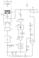
- the circuit for excitation of an ultrasonic oscillator shown in FIG. 1 comprises an ultrasonic oscillator 1, the atomizing plate of which is known per se is not shown.
- the ultrasonic vibrator 1 is via a transformer 2 excited, which ensures a galvanic separation of the ultrasonic vibrator 1 and possibly (depending on its winding conditions) allows the excitation with different voltage values of the voltage source U.
- Two transistors 4 and 5 form a push-pull output stage of the circuit, they mutually switch the voltage source U through to one half of the primary winding of the transformer 2.
- the excitation circuit is closed via a current measuring resistor 18.
- a capacitor 3 leads the current changes directly from the transistors 4 and 5 back to the voltage source U and thereby causes the voltage drop V occurring at the current measuring resistor 18 to have a direct voltage component which is proportional to the direct current consumption of the output stage.
- a driver stage 6 supplies the necessary in-phase signals for the transistors 4 and 5.
- the voltage-controlled oscillator 7 generates the frequency f with which the ultrasonic vibrator 1 is excited.
- the DC voltage drop across the resistor 18 is a direct measure of the active power consumed by the ultrasonic vibrator 1. This, in turn, is a useful measure of atomization performance.
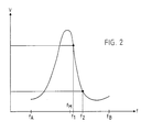
- FIG. 2 shows the profile of the DC voltage component, that is to say the time average of the voltage V across the current measuring resistor 18, that is to say also the profile of the active power consumed by the ultrasonic oscillator 1, as a function of the oscillation frequency f of the ultrasonic oscillator 1.
- the characteristic curve shown in FIG. 2 corresponds entirely to the well-known impedance curve (or reactance ver a resonance system like that of a piezo oscillator.
- the maximum recognizable in FIG. 2 corresponds to the series resonance resulting from the known equivalent circuit diagram of an oscillator, the recognizable minimum corresponds to the parallel resonance resulting from the same equivalent circuit diagram.
- the oscillator 7 in FIG. 1 is a voltage-controlled oscillator constructed using commercially available components.
- the permissible voltage swing at its control input is predetermined, the corresponding frequency swing at its frequency output can be adjusted in a known manner by the value of resistors and / or capacitors that are not shown in FIG. 1 and can be connected to the oscillator 7.
- the voltage V tapped at the current measuring resistor 18 is compared with a voltage in the comparator 21 that can be set on a potentiometer 19.
- the output signal of the comparator 21 is smoothed with the RC element formed from a resistor 9 and a capacitor 8 and supplied to the oscillator 7 as a control voltage.
- a defined operating point can thus be set and recorded on an edge of the characteristic curve in FIG. 2.
- the oscillator 7, the driver stage 6, the transistors 4 and 5, the capacitor 3, the transformer 2, the resistor 18, the comparator 21, the resistor 9 and the capacitor 8 form namely, together a controller, and together with this controller, a controlled system, which is given by the ultrasonic vibrator 1, forms a control loop.
- the oscillator 7 is now set such that with the control voltage swing at its control input (also at the capacitor 8) that can be generated by the comparator 21, only frequencies between f A and f B , that is to say only in a narrow range around the series resonance and the parallel resonance be generated. It is even better if the frequencies that can be generated are in a range that is within the range between the series resonance and the parallel resonance and is significantly smaller, such as the range between f 1 and f 2.
- the locking of the generator circuit to additional resonances which can result from a coordination between the transformer 2 and the ultrasonic vibrator 1 and which do not lead to an effective atomization, is thus ruled out.
- a special coordination between the transformer 2 and the ultrasonic oscillator 1 is therefore neither necessary nor desirable, and the effort for a filter in a resonance detection circuit is therefore also unnecessary.
- the large gain factor at the comparator 21 results in a two-point control in connection with the control voltage swing that can be generated thereby.
- This causes the ultrasonic vibrator 1 to be operated only at a frequency that corresponds to a predetermined target active power consumption.
- the operation of the ultrasonic vibrator 1 is possible due to the two-point control characteristic only at one of the two frequencies that correspond to the target active power consumption (e.g. on the higher-frequency flank of the characteristic curve shown in FIG. 2 and at the frequency f 1).
- control loop defined above is now designed so that defined control vibrations occur. This will be in the essentially achieved in that the control voltage swing generated by the comparator 21 is only incompletely smoothed by the RC element formed from the resistor 9 and the capacitor 8.
- the corresponding control oscillations which are expressed in a wobble of the excitation frequency and the oscillation frequency f of the ultrasonic oscillator 1 and consequently in an alternating voltage component superimposed on the direct voltage component, in the voltage drop V occurring at the current measuring resistor 18, are due to the interaction of the aforementioned resistor 9 and the capacitor 8 formed RC element with the current measuring resistor 18 and the capacitor 3 and with the gain factor on the comparator 21 and the active power characteristic of the ultrasonic transducer 1.
- control vibrations can only occur if the ultrasonic vibrator 1 has the characteristic curve shown in FIG. 2. This is only the case if it is atomized properly. If it is dampened too much by droplets that get stuck, it cannot show any pronounced resonance behavior according to the characteristic curve shown in FIG. 2 and the control vibrations do not occur or only occur very weakly and irregularly.
- control vibrations of the control loop can therefore be taken as a reliable criterion for proper atomization.
- the AC voltage component in the voltage drop V occurring at the current measuring resistor 18 is decoupled by a capacitor 17 and amplified by an amplifier 16.
- a rectifier 15 supplies a DC voltage as a measure of the amplitude of the amplified control vibrations.
- a comparator 13 decides, by comparing this DC voltage with a target voltage that can be set by a potentiometer 14, whether the control vibrations are sufficiently large.
- an oscillator 12 which in the present example is a rectangular oscillator, is started, so that a higher and a lower voltage alternately appear at its output. However, if the control oscillations are sufficiently large, the oscillator 12 is or remains switched off and decoupled from the control circuit by diodes 10 and 11.
- the control voltage at the control input of the oscillator 7 (and therefore also at the capacitor 8) is increased via the diode 10 and the resistor 30, so that the oscillator 7 after the resistor 9, the resistor 30 and the capacitor 8 given the time constant generates the upper limit frequency f B.
- the target current requirement at the input of the comparator 21 is increased via a diode 11 and a resistor 31. An operating point of the ultrasonic vibrator 1 is thus forced in the upper region of the characteristic curve shown in FIG. 2.
- the lower voltage subsequently appears at the output of the oscillator 12, it is decoupled from the control circuit via the diodes 10 and 11.
- the capacitor 8 discharges through the resistor 9 because the target voltage at the comparator 21 is higher than the actual voltage at this point in time and therefore the comparator output carries the lower output voltage (the target voltage is at the inverting input). Consequently, the frequency generated by the oscillator 7 decreases from f B in the direction f A.
- the period of the oscillator 12 is chosen large enough in relation to the time constant of the discharge of the capacitor 8 to ensure that the full frequency range between f B and f A is passed through.
- a power control on the ultrasonic oscillator 1 takes place in that the oscillation frequency f of the ultrasonic oscillator 1 defined by the excitation frequency is shifted between the series resonance and the parallel resonance.
- the smallest atomizing power is achieved with excitation in parallel resonance (large reactive power, low active power), the largest atomizing power with series resonance (small reactive power, large active power). Neither the excitation voltage nor the duty cycle need to be changed for power control.
- the invention has been described in connection with an ultrasonic oscillator, in particular a piezoelectric ultrasonic oscillator, the use of which, e.g. lies in the liquid atomization.
- the invention is also applicable to other resonance systems, the resonance of which takes place in a narrow frequency band and changes greatly as a function of a physical variable, this variable being intended to be maintained as precisely as possible.
- the invention is therefore generally suitable for keeping a physical variable constant by means of a control circuit which comprises a resonant body, the resonance behavior of which is strongly influenced by the physical variable in a narrow frequency band and is used to detect the changes thereof.
Landscapes
- Engineering & Computer Science (AREA)
- Mechanical Engineering (AREA)
- Special Spraying Apparatus (AREA)
- Apparatuses For Generation Of Mechanical Vibrations (AREA)
Abstract
Ein Regelkreis (1,18,19,21,9,8,7,6,5,4,3,2) umfasst den Ultraschallschwinger (1) und den spannungsgesteuerten Oszillator (7). Er hält die Wirkleistungsaufnahme auf einem Sollwert (19), der in einem Komparator (21) mit der momentanen Wirkleistungsaufnahme verglichen wird. Ein Ausgang eines Rechteckoszillators (12) ist mit dem Steuereingang des spannungsgesteuerten Oszillators (7) verbunden. Dieser Rechteckoszillator (12) wird in Betrieb gesetzt, wenn im Regelkreis keine Regelschwingungen oder nur solche auftreten, die kleiner sind als ein vorbestimmter Schwellenwert (14). Der Ausgang des Rechteckoszillators (12) ist über eine Diode (10) mit dem Steuereingang des spannungsgesteuerten Oszillators und über eine andere Diode (11) mit dem Steuereingang des Komparators (21) verbunden. Der Regelkreis stellt die Wirkleistung mittels der Anregungsfrequenz zwischen der Serienresonanz und der Parallelresonanz ein. Am Oszillator (7) wird das Zusatzsignal zusätzlich zum Regelungssignal des Regelkreises angelegt. Die Periode des Zusatzsignals ist länger als die Änderungszeitkonstante am Steuereingang des Oszillators (7) und der Hub des Zusatzsignals ist so bemessen, dass die Frequenz des Oszillators (7) einen vorbestimmten Frequenzbereich durchläuft. Der vom Regelkreis allein erzeugbare Frequenzhub kann kleiner sein als der Frequenzabstand zwischen der Serienresonanz und der Parallelresonanz. Die Spannung am Ultraschallschwinger (1) kann von konstanter Amplitude sein. Eine Verwendung ist die Zerstäubung einer Flüssigkeit durch einen mit einem Zerstäuberteller versehenen Ultraschallschwinger.A control loop (1,18,19,21,9,8,7,6,5,4,3,2) comprises the ultrasonic oscillator (1) and the voltage controlled oscillator (7). It keeps the active power consumption at a target value (19), which is compared in a comparator (21) with the current active power consumption. An output of a square wave oscillator (12) is connected to the control input of the voltage controlled oscillator (7). This square wave oscillator (12) is put into operation if no control oscillations or only those which are smaller than a predetermined threshold value (14) occur in the control loop. The output of the rectangular oscillator (12) is connected via a diode (10) to the control input of the voltage-controlled oscillator and via another diode (11) to the control input of the comparator (21). The control loop adjusts the active power by means of the excitation frequency between the series resonance and the parallel resonance. The additional signal is applied to the oscillator (7) in addition to the control signal of the control loop. The period of the additional signal is longer than the change time constant at the control input of the oscillator (7) and the stroke of the additional signal is dimensioned such that the frequency of the oscillator (7) runs through a predetermined frequency range. The frequency swing that can be generated by the control loop alone can be smaller than the frequency distance between the series resonance and the parallel resonance. The voltage at the ultrasonic transducer (1) can be of constant amplitude. One use is the atomization of a liquid by an ultrasonic vibrator provided with an atomizing plate.
Description
Die Erfindung betrifft ein Verfahren und eine Schaltung zur Anregung eines Ultraschallschwingers sowie deren Verwendung zur Zerstäubung einer Flüssigkeit.The invention relates to a method and a circuit for excitation of an ultrasonic vibrator and their use for atomizing a liquid.
Die Möglichkeit, Flüssigkeiten mit Hilfe von piezoelektrischen Ultraschallschwingern zu zerstäuben, ist wohlbekannt. Beispielsweise sind im Aufsatz von W.-D. Drews "Flüssigkeitszerstäubung durch Ultraschall" in "Elektronik" (1979), Heft 10, Seiten 83-90 das Prinzip dieses Verfahrens, ein mit einem Zerstäuberteller versehener Ultraschallschwinger und eine Schaltung zur Anregung dieses Ultraschallschwingers kurz beschrieben.The ability to atomize liquids using ultrasonic piezoelectric transducers is well known. For example, in the essay by W.-D. Drew's "Liquid atomization by ultrasound" in "Electronics" (1979), No. 10, pages 83-90 briefly describes the principle of this method, an ultrasonic oscillator provided with an atomizing plate and a circuit for exciting this ultrasonic oscillator.
Die technische Realisierung der Zerstäubung einer Flüssigkeit mit Hilfe eines Ultraschallschwingers wird aber durch mehrere Probleme erschwert: Da eine Zerstäubung nur in der Nähe der Resonanz des Ultraschallschwingers (samt seinem Zerstäuberteller) möglich ist, muss die nötige Anregungsfrequenz sehr genau eingehalten werden. Das Einrasten des Oszillators der Anregungsschaltung auf eine Scheinresonanz, die keiner wirksamen Zerstäubung entspricht, muss mit Sicherheit ausgeschlossen werden.
Die Anregungsschaltung muss in der Lage sein, Veränderungen der nötigen Anregungsfrequenz als Funktion verschiedener Parameter aufzufangen. Solche Parameter sind beispielsweise die Fertigungstoleranzen der mechanischen Komponenten des Ultraschallschwingers (insbesondere seines Zerstäubertellers), die Variationen der mechanischen und elektrischen Kenngrössen der zu seiner Her stellung verwendeten Piezokeramik, die Betriebstemperatur des Ultraschallschwingers (sehr wichtig bei der Verwendung in Brennern), die Alterung des Ultraschallschwingers, die sich darauf bildenden Ablagerungen (wie z.B. Russ und Harze bei der Anwendung in Brennern), und auch die Fertigungs-, Justier- und sonstigen Toleranzen in der Anregungsschaltung.
Die sichere Erkennung eines Aussetzens der Zerstäubung muss gewährleistet sein. Wenn das Aussetzen durch am Zerstäuberteller hängenbleibende Tröpfchen verursacht wird, muss auch ihr Abschleudern vom Zerstäuberteller gewährleistet sein
Eine praktische Anforderung an die industrielle Einsetzbarkeit ist die Austauschbarkeit der Anregungsschaltung und des Ultraschallschwingers selbst oder gegebenenfalls dessen Zerstäubertellers, und zwar ohne jegliche Abgleicharbeiten und ohne hohen Toleranzanforderungen an die Ersatzteile.The technical realization of the atomization of a liquid with the help of an ultrasonic vibrator is complicated by several problems: Since atomization is only possible in the vicinity of the resonance of the ultrasonic vibrator (including its atomizer plate), the necessary excitation frequency must be adhered to very precisely. The locking of the oscillator of the excitation circuit to an apparent resonance that does not correspond to an effective atomization must be excluded with certainty.
The excitation circuit must be able to absorb changes in the required excitation frequency as a function of various parameters. Such parameters are, for example, the manufacturing tolerances of the mechanical components of the ultrasonic vibrator (in particular its atomizing plate), the variations in the mechanical and electrical parameters of its origin Position used piezoceramic, the operating temperature of the ultrasonic transducer (very important when used in burners), the aging of the ultrasonic transducer, the deposits that form on it (such as soot and resins when used in burners), and also the manufacturing, adjustment and other tolerances in the excitation circuit.
The reliable detection of atomization suspension must be guaranteed. If the exposure is caused by droplets remaining on the atomizing plate, it must also be ensured that they are thrown off the atomizing plate
A practical requirement for industrial applicability is the interchangeability of the excitation circuit and the ultrasonic transducer itself or, if appropriate, its atomizing plate, without any adjustment work and without high tolerance requirements for the spare parts.
Zur Erreichung des bestmöglichen Wirkungsgrades muss sich die Zerstäubungsfähigkeit des Ultraschallschwingers bzw. dessen Zerstäubertellers selbsttätig regeln können, ohne dass eine Bedienungsperson eingreifen und z.B. die Anregungsspannung oder das Tastverhältnis der Ansteuerfrequenz verändern muss.In order to achieve the best possible efficiency, the ability to atomize the ultrasonic vibrator or its atomizing plate must be able to regulate itself without any intervention by an operator and e.g. the excitation voltage or the duty cycle of the control frequency must change.
Zur Lösung dieser Probleme wurden bereits verschiedene Verfahren bzw. Schaltungen vorgeschlagen.Various methods and circuits have already been proposed to solve these problems.
In DE-3222425 wurde vorgeschlagen, den Ultraschallschwinger über ein Anpassnetzwerk anzuregen, das unter anderem dazu bestimmt ist, das Anschwingen des Ultraschallschwingers auf Oberwellen seiner Resonanzfrequenz zu unterdrücken. Die Gleichstromkomponente des Resonatorstroms dient der Regelung des Anregungssstromes und die Wechselstromkomponente des Re sonatorstroms dient der Regelung der Anregungsfrequenz, wobei ein Bandpass nur die Frequenzkomponente auf der Resonanz-Sollfrequenz des Ultraschallschwingers durchlässt. Bei Ausfall der Resonanz wird die Anregungsfrequenz gewobbelt, um den Resonanzpunkt zu durchlaufen und das Wiedereinrasten zu erreichen. Nachteilig ist bei dieser Lösung, dass die Schaltung auf den Ultraschallschwinger und insbesondere auf seine Resonanz-Sollfrequenz abgestimmt ist, so dass der Betrieb des Ultraschallschwingers den Änderungen einiger der vorstehend aufgeführten Parameter nicht nachgeführt werden kann und auch die leichte Austauschbarkeit von Komponenten durch Ersatzteile nicht gewährleistet ist. Eine zuverlässige Funktion ist beim Anschwingen vor allem unter Last und bei sich ändernden Betriebsbedingungen nicht gewährleistet, da sich die Impedanz und damit die Phasenbeziehungen zwischen Strom und Spannung des Ultraschallschwingers bei Belastungsänderungen stark ändern und damit eine Nachführung der optimalen Schwingfrequenz, abgeleitet aus Phasenbeziehungen zwischen Strom und Spannung im Ultraschallschwinger, nicht möglich ist. Mittels einer Induktivität eine echte Kompensation der Kapazität des Ultraschallschwingers zu erreichen, ist wegen der sich bei Belastungsänderungen ändernden Kapazität nicht möglich.In DE-3222425 it was proposed to excite the ultrasonic vibrator via a matching network which, among other things, is intended to suppress the oscillation of the ultrasonic vibrator at harmonics of its resonance frequency. The DC component of the resonator current is used to regulate the excitation current and the AC component of the Re sonator current is used to regulate the excitation frequency, with a bandpass only passing the frequency component at the desired resonance frequency of the ultrasonic oscillator. If the resonance fails, the excitation frequency is swept in order to pass through the resonance point and to achieve re-engagement. The disadvantage of this solution is that the circuit is matched to the ultrasonic oscillator and in particular to its resonance target frequency, so that the operation of the ultrasonic oscillator cannot be tracked to the changes in some of the parameters listed above and the easy interchangeability of components with spare parts does not guarantee is. A reliable function is not guaranteed when starting up, especially under load and with changing operating conditions, since the impedance and thus the phase relationships between the current and voltage of the ultrasonic transducer change significantly with changes in load, and thus a tracking of the optimal oscillation frequency, derived from the phase relationships between current and Voltage in the ultrasonic transducer is not possible. It is not possible to achieve a real compensation of the capacitance of the ultrasonic vibrator by means of an inductor, because of the capacitance changing with changes in load.
In etwas anderer Ausbildung wurde ähnliches in US-4275363 vorgeschlagen, wobei auch die gleichen, vorstehend erwähnten Nachteile entstehen.In a somewhat different design, similar has been proposed in US-4275363, whereby the same disadvantages mentioned above also arise.
In DE-3314609 wurde vorgeschlagen, den Ultraschallschwinger mit getakteter Anregungsleistung ("Bursts") unter Verwendung von jeweils verschiedenen Werten der Anregungsleistung zu betreiben. Nachteilig ist dabei, dass für den Frequenzabgleich und die Steuerung der Anregungsleistung nicht das Resonanzverhalten des Ultraschallschwingers, sondern das freie Abklingen seiner Schwingung herangezogen werden, was grundsätzlich keine mit dem Istzustand linear variierende Werte liefern kann.In DE-3314609 it was proposed to operate the ultrasonic oscillator with clocked excitation power ("bursts") using different values of the excitation power. The disadvantage here is that the frequency adjustment and the control of the excitation power are based not on the resonance behavior of the ultrasonic oscillator, but on the free decay of its oscillation, which in principle cannot provide values that vary linearly with the actual state.
In etwas anderer Ausbildung wurde ähnliches in DE-3401735 vorgeschlagen, wobei auch die gleichen, vorstehend erwähnten Nachteile entstehen.In a somewhat different design, something similar was proposed in DE-3401735, the same disadvantages mentioned above also occurring.
In DE-3534853 wurde vorgeschlagen, den Ultraschallschwinger mit getakteter Anregungsleistung ("Bursts") zu betreiben und für den automatischen Frequenzabgleich eine Strommessung zu und während ganz bestimmten Zeiten vorzunehmen. Nachteilig und insbesondere kostspielig ist dabei die nötige Zwischenspeicherung des Wertes der Strommessung sowie die genaue Synchronisation der Mess- und Steuerabläufe.In DE-3534853 it was proposed to operate the ultrasonic oscillator with clocked excitation power ("bursts") and to carry out a current measurement for and during very specific times for the automatic frequency adjustment. A disadvantageous and, in particular, costly is the need to temporarily store the value of the current measurement and the precise synchronization of the measurement and control processes.
Aufgabe der Erfindung ist es, die vorangehend erwähnten Nachteile auf kostengünstige Weise zu überwinden.The object of the invention is to overcome the disadvantages mentioned above in a cost-effective manner.
Diese Aufgabe wird durch das im Anspruch 1 angegebene Verfahren gelöst. Eine Schaltung zur Ausführung dieses Verfahrens ist im Anspruch 4 angegeben. Vorteilhafte Weiterbildungen des erfindungsgemässen Verfahrens und der erfindungsgemässen Schaltung ergeben sich aus den abhängigen Ansprüchen.This object is achieved by the method specified in
Im nachstehenden wird ein Beispiel einer Ausbildung der Erfindung anhand der Zeichnungen näher erläutert. Es zeigen:
- Fig. 1 ein Blockschaltbild einer erfindungsgemässen Schaltung zur Anregung eines Ultraschallschwingers, und
- Fig. 2 den Verlauf der Spannung an einem in Fig. 1 dargestellten Strommesswiderstand als Funktion der Anregungsfrequenz des Ultraschallschwingers.
- 1 is a block diagram of an inventive circuit for exciting an ultrasonic vibrator, and
- Fig. 2 shows the curve of the voltage across a current measuring resistor shown in Fig. 1 as a function of the excitation frequency of the ultrasonic vibrator.
Die in Fig. 1 dargestellte Schaltung zur Anregung eines Ultraschallschwingers umfasst einen Ultraschallschwinger 1, dessen an sich bekannter Zerstäuberteller nicht dargestellt ist. Der Ultraschallschwinger 1 wird über einen Transformator 2 angeregt, der eine galvanische Trennung des Ultraschallschwingers 1 gewährleistet und gegebenenfalls (je nach seinen Windungsverhältnissen) die Anregung mit verschiedenen Spannungswerten der Spannungsquelle U gestattet. Zwei Transistoren 4 und 5 bilden eine Gegentakt-Endstufe der Schaltung, sie schalten wechselseitig die Spannungsquelle U auf je eine Hälfe der Primärwicklung des Transformators 2 durch. Der Anregungsstromkreis wird über einen Strommesswiderstand 18 geschlossen. Ein Kondensator 3 führt die Stromänderungen direkt von den Transistoren 4 und 5 auf die Spannungsquelle U zurück und bewirkt dadurch, dass der am Strommesswiderstand 18 auftretende Spannungsabfall V einen Gleichspannungsanteil aufweist, welcher der Gleichstromaufnahme der Endstufe proportional ist. Eine Treiberstufe 6 liefert die für die Transistoren 4 und 5 notwendigen phasenrichtigen Signale. Der spannungsgesteuerte Oszillator 7 erzeugt die Frequenz f, mit welcher die Anregung des Ultraschallschwingers 1 erfolgt.The circuit for excitation of an ultrasonic oscillator shown in FIG. 1 comprises an
Da die Verluste in den Transistoren 4 und 5, im Transformator 2, im Kondensator 3 sowie die durch Blindströme hervorgerufenen Verluste in der Sekundärspule des Transformators 2 (aufgrund der Schwingerkapazität) genügend klein gehalten werden können, ist der Gleichspannungsabfall am Widerstand 18 ein direktes Mass für die vom Ultraschallschwinger 1 aufgenommene Wirkleistung. Diese ist ihrerseits ein brauchbares Mass für die Zerstäubungsleistung.Since the losses in the transistors 4 and 5, in the
Fig. 2 zeigt den Verlauf des Gleichspannungsanteils, d.h. gegebenenfalls des zeitlichen Mittelwerts der Spannung V am Strommesswiderstand 18, also auch den Verlauf der vom Ultraschallschwinger 1 aufgenommenen Wirkleistung, als Funktion der Schwingungsfrequenz f des Ultraschallschwingers 1. Auf der Abszisse sind die Schwingungsfrequenzen f und auf der Ordinate die am Strommesswiderstand 18 gemessene Spannungen V eingetragen. Die in Fig. 2 dargestellte Kennlinie entspricht durchaus dem gut bekannten Impedanzverlauf (bzw. Reaktanzver lauf) eines Resonanzsystems wie das eines Piezoschwingers. Das auf Fig. 2 erkennbare Maximum entspricht der sich aus dem bekannten Ersatzschaltbild eines Schwingers ergebenden Serienresonanz, das erkennbare Minimum entspricht der sich aus demselben Ersatzschaltbild ergebenden Parallelresonanz. Das Verhältnis zwischen Maximum und Minimum wird im wesentlichen durch das Impedanzverhalten des Ultraschallschwingers 1 festgelegt. Zwischen dem Maximum und dem Minimum liegt eine abfallende Flanke der Kennlinie, auf der beispielsweise bei einer Frequenz f₁ eine grosse, bei einer Frequenz f₂ eine kleine Zerstäubungsleistung erhalten wird. Alle Anregungsfrequenzen, die zu im praktischen Betrieb des Ultraschallschwingers 1 auftretenden Resonanzen desselben führen, liegen zwischen einer unteren Grenzfrequenz fA und einer oberen Grenzfrequenz fB, deren Mittelwert fM = (fA+fB)/2 in Nähe der maximalen Wirkleistung liegt.2 shows the profile of the DC voltage component, that is to say the time average of the voltage V across the
Der Oszillator 7 der Fig. 1 ist ein mit handelsüblichen Bauelementen aufgebauter spannungsgesteuerter Oszillator. Der zulässige Spannungshub an seinem Steuereingang ist vorgegeben, der entsprechende Frequenzhub an seinem Frequenzausgang ist auf bekannte Weise durch den Wert von am Oszillator 7 anschliessbaren, in Fig. 1 nicht dargestellten Widerständen und/oder Kondensatoren einstellbar.The oscillator 7 in FIG. 1 is a voltage-controlled oscillator constructed using commercially available components. The permissible voltage swing at its control input is predetermined, the corresponding frequency swing at its frequency output can be adjusted in a known manner by the value of resistors and / or capacitors that are not shown in FIG. 1 and can be connected to the oscillator 7.
Die am Strommesswiderstand 18 abgegriffene Spannung V wird mit einer an einem Potentiometer 19 einstellbaren Spannung im Komparator 21 verglichen. Das Ausgangssignal des Komparators 21 wird mit dem aus einem Widerstand 9 und einem Kondensator 8 gebildeten RC-Glied geglättet und dem Oszillator 7 als Steuerspannung zugeführt. Mit dem Potentiometer 19 kann somit ein definierter Betriebspunkt an einer Flanke der Kennlinie der Fig. 2 eingestellt und festgehalten werden. Der Oszillator 7, die Treiberstufe 6, die Transistoren 4 und 5, der Kondensator 3, der Transformator 2, der Widerstand 18, der Komparator 21, der Widerstand 9 und der Kondensator 8 bilden nämlich zusammen einen Regler, und zusammen mit diesem Regler bildet eine Regelstrecke, die durch den Ultraschallschwinger 1 gegeben ist, einen Regelkreis.The voltage V tapped at the
Der Oszillator 7 ist nun so eingestellt, dass mit dem an seinem Steuereingang (also auch am Kondensator 8) anliegenden, vom Komparator 21 erzeugbaren Steuerspannungshub nur Frequenzen zwischen fA und fB, also nur in einem engen Bereich um die Serienresonanz und die Parallelresonanz herum erzeugt werden. Es ist noch besser, wenn die erzeugbaren Frequenzen in einem Bereich liegen, der innerhalb des Bereiches zwischen der Serienresonanz und der Parallelresonanz liegt und deutlich kleiner ist, wie beispielsweise der Bereich zwischen f₁ und f₂. Das Einrasten der Generatorschaltung auf zusätzliche Resonanzen, die sich durch eine Abstimmung zwischen dem Transformator 2 und dem Ultraschallschwinger 1 ergeben können und nicht zu einer wirksamen Zerstäubung führen, ist damit ausgeschlossen. Eine besondere Abstimmung zwischen dem Transformator 2 und dem Ultraschallschwinger 1 ist dadurch weder notwendig noch erwünscht, und es erübrigt sich dadurch auch der Aufwand für einen Filter in einer Resonanzerkennungsschaltung.The oscillator 7 is now set such that with the control voltage swing at its control input (also at the capacitor 8) that can be generated by the
Der grosse Verstärkungsfaktor am Komparator 21 ergibt im Zusammenhang mit dem davon erzeugbaren Steuerspannungshub eine Zweipunktregelung. Diese bewirkt, dass der Ultraschallschwinger 1 nur bei einer solchen Frequenz betrieben wird, die einer vorbestimmten Soll-Wirkleistungsaufnahme entspricht. Ausserdem ist der Betrieb des Ultraschallschwingers 1 aufgrund der Zweipunkt-Regelcharakteristik nur bei einer der beiden Frequenzen möglich, die der Soll-Wirkleistungsaufnahme entsprechen (z.B. auf der höherfrequenten Flanke der in Fig. 2 dargestellten Kennlinie und bei der Frequenz f₁).The large gain factor at the
Der vorstehend definierte Regelkreis ist nun so ausgelegt, dass definierte Regelschwingungen auftreten. Dies wird im wesentlichen dadurch erreicht, dass der vom Komparator 21 erzeugte Steuerspannungshub von dem aus dem Widerstand 9 und dem Kondensator 8 gebildeten RC-Glied nur unvollständig geglättet wird. Die entsprechenden Regelschwingungen, die sich in einem Wobbeln der Anregungsfrequenz und der Schwingungsfrequenz f des Ultraschallschwingers 1 und folglich in einem dem Gleichspannungsanteil überlagerten Wechselspannungsanteil in dem am Strommesswiderstand 18 auftretenden Spannungsabfall V äussern, sind durch das Zusammenwirken des vorgenannten, aus dem Widerstand 9 und dem Kondensator 8 gebildeten RC-Glied mit dem Strommesswiderstand 18 und dem Kondensator 3 sowie mit dem Verstärkungsfaktor am Komparator 21 und der Wirkleistungskennlinie des Ultraschallschwingers 1 gegeben.The control loop defined above is now designed so that defined control vibrations occur. This will be in the essentially achieved in that the control voltage swing generated by the
Da der Ultraschallschwinger 1 integraler Bestandteil des Regelkreises ist, können dies Regelschwingungen nur dann auftreten, wenn der Ultraschallschwinger 1 die in Fig. 2 dargestellte Kennlinie aufweist. Dies ist nur dann der Fall, wenn er ordnungsgemäss zerstäubt. Wird er durch hängenbleibende Tröpfchen zu stark gedämpft, so kann er kein ausgeprägtes Resonanzverhalten gemäss der in Fig. 2 dargestellten Kennlinie zeigen und die Regelschwingungen treten nicht oder nur sehr schwach und unregelmässig auf.Since the
Daher kann das Auftreten von definierten Regelschwingungen des Regelkreises als zuverlässiges Kriterium für eine ordnungsgemässe Zerstäubung genommen werden. Um diese Regelschwingungen zu erkennen, wird der Wechselspannungsanteil in dem am Strommesswiderstand 18 auftretenden Spannungsabfall V durch einen Kondensator 17 abgekoppelt und durch einen Verstärker 16 verstärkt. Ein Gleichrichter 15 liefert eine Gleichspannung als Mass der Amplitude der verstärkten Regelschwingungen. Ein Komparator 13 entscheidet durch Vergleich dieser Gleichspannung mit einer durch einen Potentiometer 14 einstellbaren Sollspannung, ob die Regelschwingungen genügend gross sind. Sind die Regelschwingungen nicht vorhanden oder zu schwach (was z.B. auch beim Einschalten des Generators vorkommt), so wird ein Oszillator 12, der im vorliegenden Beispiel ein Rechteck-Oszillator ist, gestartet, so dass an seinem Ausgang wechselweise eine höhere und eine niedrigere Spannung erscheint. Sind die Regelschwingungen jedoch genügend gross, so wird bzw. bleibt der Oszillator 12 ausgeschaltet und durch Dioden 10 und 11 vom Regelkreis abgekoppelt.The occurrence of defined control vibrations of the control loop can therefore be taken as a reliable criterion for proper atomization. In order to recognize these control vibrations, the AC voltage component in the voltage drop V occurring at the current measuring
Beim Erscheinen der höheren Spannung am Ausgang des Oszillators 12 wird über die Diode 10 und den Widerstand 30 die Steuerspannung am Steuereingang des Oszillators 7 (also auch am Kondensator 8) erhöht, so dass der Oszillator 7 nach einer durch den Widerstand 9, den Widerstand 30 und den Kondensator 8 gegebenen Zeitkonstante die obere Grenzfrequenz fB erzeugt. Gleichzeitig wird die Sollstrom-Anforderung am Eingang des Komparators 21 über eine Diode 11 und einem Widerstand 31 erhöht. Damit wird ein Betriebspunkt des Ultraschallschwingers 1 im oberen Bereich der in Fig. 2 dargestellten Kennlinie erzwungen. Beim darauffolgenden Erscheinen der niedrigeren Spannung am Ausgang des Oszillators 12 wird dieser über die Dioden 10 und 11 vom Regelkreis abgekoppelt. Der Kondensator 8 entlädt sich dabei über den Widerstand 9, weil die Sollspannung am Komparator 21 zu diesem Zeitpunkt höher ist als die Ist-Spannung und daher der Komparatorausgang die niedrigere Ausgangsspannung führt (die Sollspannung liegt am invertierenden Eingang). Folglich sinkt die vom Oszillator 7 erzeugte Frequenz von fB in Richtung fA. Dabei wird die Periode des Oszillators 12 im Verhältnis zur Zeitkonstante der Entladung des Kondensators 8 gross genug gewählt, um zu gewährleisten, dass ver volle Frequenzbereich zwischen fB und fA durchlaufen wird.When the higher voltage appears at the output of the
Solange die Ursache der Verstimmung des Ultraschallschwingers 1 nicht behoben ist (solange der Ultraschallschwinger 1 noch nicht auf die Anregungsfrequenz eingerastet oder das hängengebliebene Tröpfchen noch nicht abgeschüttelt worden ist), findet daher ein Frequenzdurchlauf zwischen fB und fA statt. Ist gegebenenfalls das Tröpfchen abgeschüttelt worden und wird vom Ultraschallschwinger 1 ein Resonanzverhalten gemäss der in Fig. 2 dargestellten Kennlinie erreicht oder gegebenenfalls wiedererreicht, so erscheinen die Regelschwingungen, der Oszillator 12 wird ausgeschaltet (sein Ausgang wird auf die niedrigere Spannung gesetzt) und durch die Dioden 10 und 11 vom Regelkreis abgekoppelt.As long as the cause of the detuning of the
Eine Leistungsregelung am Ultraschallschwinger 1 erfolgt dadurch, dass die durch die Anregungsfrequenz definierte Schwingungsfrequenz f des Ultraschallschwingers 1 zwischen der Serienresonanz und der Parallelresonanz verschoben wird. Kleinste Zerstäuberleistung wird bei Anregung in Parallelresonanz (grosse Blindleistung, geringe Wirkleistung), grösste Zerstäuberleistung bei Serienresonanz (kleine Blindleistung, grosse Wirkleistung) erreicht. Zur Leistungsregelung brauchen daher weder die Anregungsspannung noch das Tastverhältnis verändert zu werden.A power control on the
Im vorstehenden ist die Erfindung im Zusammenhang mit einem Ultraschallschwinger, insbesondere einem piezoelektrischen Ultraschallschwinger beschrieben worden, dessen Einsatz z.B. in der Flüssigkeitszerstäubung liegt. Die Erfindung ist jedoch ebenfalls auf andere Resonanzsysteme anwendbar, deren Resonanz in einem engen Frequenzband stattfindet und sich dabei in Abhängigkeit von einer physikalischen Grösse stark ändert, wobei diese Grösse möglichst genau beibehalten werden soll. Die Erfindung eignet sich also allgemein zur Konstanthaltung einer physikalischen Grösse mittels eines Regelkreises, der einen resonanzfähigen Körper umfasst, dessen Resonanzverhalten in einem engen Frequenzband stark von der physikalischen Grösse beeinflusst wird und zur Detektion der Änderungen derselben herangezogen wird.In the above, the invention has been described in connection with an ultrasonic oscillator, in particular a piezoelectric ultrasonic oscillator, the use of which, e.g. lies in the liquid atomization. However, the invention is also applicable to other resonance systems, the resonance of which takes place in a narrow frequency band and changes greatly as a function of a physical variable, this variable being intended to be maintained as precisely as possible. The invention is therefore generally suitable for keeping a physical variable constant by means of a control circuit which comprises a resonant body, the resonance behavior of which is strongly influenced by the physical variable in a narrow frequency band and is used to detect the changes thereof.
Claims (5)
Applications Claiming Priority (2)
| Application Number | Priority Date | Filing Date | Title |
|---|---|---|---|
| CH3155/87 | 1987-08-17 | ||
| CH315587 | 1987-08-17 |
Publications (1)
| Publication Number | Publication Date |
|---|---|
| EP0303944A1 true EP0303944A1 (en) | 1989-02-22 |
Family
ID=4249804
Family Applications (1)
| Application Number | Title | Priority Date | Filing Date |
|---|---|---|---|
| EP88112934A Withdrawn EP0303944A1 (en) | 1987-08-17 | 1988-08-09 | Method and circuit for the excitation of an ultrasonic vibrator and their use in the atomisation of a liquid |
Country Status (3)
| Country | Link |
|---|---|
| US (1) | US4868521A (en) |
| EP (1) | EP0303944A1 (en) |
| CS (1) | CS550488A3 (en) |
Cited By (8)
| Publication number | Priority date | Publication date | Assignee | Title |
|---|---|---|---|---|
| EP0421439A2 (en) * | 1989-10-05 | 1991-04-10 | Firma J. Eberspächer | Ultrasonic atomiser |
| EP0442510A1 (en) * | 1990-02-14 | 1991-08-21 | Siemens Aktiengesellschaft | Method and apparatus for ultrasonic liquid atomization |
| US5216338A (en) * | 1989-10-05 | 1993-06-01 | Firma J. Eberspacher | Circuit arrangement for accurately and effectively driving an ultrasonic transducer |
| DE102007002315A1 (en) * | 2007-01-16 | 2008-07-24 | Health & Life Co., Ltd., Chung Ho | Piezoelectric drive system for medical atomizer, has frequency generator for generating electric signal with frequency value and control interface is electrically connected with frequency generator |
| US7458372B2 (en) | 2002-10-30 | 2008-12-02 | Pari Pharma Gmbh | Inhalation therapy device |
| CN101024216B (en) * | 2005-12-29 | 2012-11-14 | 杜凯恩公司 | Systems for providing power to ultrasonic welding probes |
| FR3044242A1 (en) * | 2015-11-30 | 2017-06-02 | Areco Finances Et Tech - Arfitec | A PIEZOELECTRIC TRANSDUCER DEVICE COUPLED TO AN ACOUSTIC CONCENTRATOR WITH A DETECTOR OF THE INTERNAL LIQUID LEVEL |
| DE102021110155A1 (en) | 2021-04-21 | 2022-10-27 | Endress+Hauser Conducta Gmbh+Co. Kg | Checking a device for generating ultrasound |
Families Citing this family (6)
| Publication number | Priority date | Publication date | Assignee | Title |
|---|---|---|---|---|
| US5710491A (en) * | 1988-10-19 | 1998-01-20 | Nikon Corporation | Driving control device for vibration wave motor |
| US5276376A (en) * | 1992-06-09 | 1994-01-04 | Ultrasonic Power Corporation | Variable frequency ultrasonic generator with constant power output |
| US5563464A (en) * | 1993-02-09 | 1996-10-08 | Olympus Optical Co., Ltd. | Circuit for rotating ultrasonic motor |
| US6148126A (en) * | 1998-10-07 | 2000-11-14 | Zheng; Yu | Dual fiber optical collimator |
| JP2001016877A (en) * | 1999-06-25 | 2001-01-19 | Asmo Co Ltd | Ultrasonic motor drive circuit |
| CN112107030B (en) * | 2019-06-04 | 2022-02-15 | 湖南中烟工业有限责任公司 | Ultrasonic atomization sheet oscillation control method and control system |
Citations (7)
| Publication number | Priority date | Publication date | Assignee | Title |
|---|---|---|---|---|
| CH415137A (en) * | 1962-01-29 | 1966-06-15 | Exxon Research Engineering Co | Electronic oscillator with a load operated by it with at least one resonance frequency |
| US3432691A (en) * | 1966-09-15 | 1969-03-11 | Branson Instr | Oscillatory circuit for electro-acoustic converter |
| DE2338503A1 (en) * | 1972-07-31 | 1974-02-21 | Matsushita Electric Ind Co Ltd | ULTRASOUND GENERATOR |
| US3975650A (en) * | 1975-01-30 | 1976-08-17 | Payne Stephen C | Ultrasonic generator drive circuit |
| DE3013964A1 (en) * | 1980-04-11 | 1981-10-22 | Jürgen F. 8011 Poing Strutz | Circuits for stabilising ultrasonic generator and preventing drying - in prodn. of aerosols for breathing machines |
| US4445064A (en) * | 1983-04-25 | 1984-04-24 | E. I. Du Pont De Nemours And Company | Self resonant power supply for electro-acoustical transducer |
| US4583529A (en) * | 1983-05-23 | 1986-04-22 | Mettler Electronics Corporation | High efficiency high frequency power oscillator |
Family Cites Families (1)
| Publication number | Priority date | Publication date | Assignee | Title |
|---|---|---|---|---|
| JPS5916572A (en) * | 1982-07-21 | 1984-01-27 | 多賀電気株式会社 | Method of controlling drive frequency of ultrasonic converter drive |
-
1988
- 1988-08-08 CS CS885504A patent/CS550488A3/en unknown
- 1988-08-09 EP EP88112934A patent/EP0303944A1/en not_active Withdrawn
- 1988-08-16 US US07/232,731 patent/US4868521A/en not_active Expired - Fee Related
Patent Citations (7)
| Publication number | Priority date | Publication date | Assignee | Title |
|---|---|---|---|---|
| CH415137A (en) * | 1962-01-29 | 1966-06-15 | Exxon Research Engineering Co | Electronic oscillator with a load operated by it with at least one resonance frequency |
| US3432691A (en) * | 1966-09-15 | 1969-03-11 | Branson Instr | Oscillatory circuit for electro-acoustic converter |
| DE2338503A1 (en) * | 1972-07-31 | 1974-02-21 | Matsushita Electric Ind Co Ltd | ULTRASOUND GENERATOR |
| US3975650A (en) * | 1975-01-30 | 1976-08-17 | Payne Stephen C | Ultrasonic generator drive circuit |
| DE3013964A1 (en) * | 1980-04-11 | 1981-10-22 | Jürgen F. 8011 Poing Strutz | Circuits for stabilising ultrasonic generator and preventing drying - in prodn. of aerosols for breathing machines |
| US4445064A (en) * | 1983-04-25 | 1984-04-24 | E. I. Du Pont De Nemours And Company | Self resonant power supply for electro-acoustical transducer |
| US4583529A (en) * | 1983-05-23 | 1986-04-22 | Mettler Electronics Corporation | High efficiency high frequency power oscillator |
Cited By (11)
| Publication number | Priority date | Publication date | Assignee | Title |
|---|---|---|---|---|
| EP0421439A2 (en) * | 1989-10-05 | 1991-04-10 | Firma J. Eberspächer | Ultrasonic atomiser |
| DE3933300A1 (en) * | 1989-10-05 | 1991-04-18 | Eberspaecher J | ULTRASONIC SPRAYER |
| EP0421439A3 (en) * | 1989-10-05 | 1992-03-18 | Firma J. Eberspaecher | Ultrasonic atomiser |
| US5216338A (en) * | 1989-10-05 | 1993-06-01 | Firma J. Eberspacher | Circuit arrangement for accurately and effectively driving an ultrasonic transducer |
| EP0442510A1 (en) * | 1990-02-14 | 1991-08-21 | Siemens Aktiengesellschaft | Method and apparatus for ultrasonic liquid atomization |
| US7458372B2 (en) | 2002-10-30 | 2008-12-02 | Pari Pharma Gmbh | Inhalation therapy device |
| CN101024216B (en) * | 2005-12-29 | 2012-11-14 | 杜凯恩公司 | Systems for providing power to ultrasonic welding probes |
| DE102007002315A1 (en) * | 2007-01-16 | 2008-07-24 | Health & Life Co., Ltd., Chung Ho | Piezoelectric drive system for medical atomizer, has frequency generator for generating electric signal with frequency value and control interface is electrically connected with frequency generator |
| FR3044242A1 (en) * | 2015-11-30 | 2017-06-02 | Areco Finances Et Tech - Arfitec | A PIEZOELECTRIC TRANSDUCER DEVICE COUPLED TO AN ACOUSTIC CONCENTRATOR WITH A DETECTOR OF THE INTERNAL LIQUID LEVEL |
| WO2017093655A1 (en) * | 2015-11-30 | 2017-06-08 | Areco Finances Et Technologie - Arfitec | Spraying device comprising a piezoelectric transducer coupled to an acoustic concentrator, with detection of the internal liquid level |
| DE102021110155A1 (en) | 2021-04-21 | 2022-10-27 | Endress+Hauser Conducta Gmbh+Co. Kg | Checking a device for generating ultrasound |
Also Published As
| Publication number | Publication date |
|---|---|
| US4868521A (en) | 1989-09-19 |
| CS550488A3 (en) | 1992-11-18 |
Similar Documents
| Publication | Publication Date | Title |
|---|---|---|
| EP0254237B1 (en) | Method for phase controlled power- and frequency adjustement of an ultrasonic transducer and apparatus for application of the method | |
| EP0303944A1 (en) | Method and circuit for the excitation of an ultrasonic vibrator and their use in the atomisation of a liquid | |
| EP0340470A1 (en) | Method and circuit for driving an ultrasonic transducer, and their use in atomizing a liquid | |
| DE2912171C2 (en) | DC / DC converter working as a switching regulator | |
| DE2338503C3 (en) | Circuit arrangement for energizing the transducer of an ultrasonic atomizer | |
| CH678404A5 (en) | ||
| DE4142398C2 (en) | Control device for an oscillating conveyor vibrating in the resonance frequency | |
| DE4412900C2 (en) | Method and device for determining the onset of a flood of an ultrasonic atomizer | |
| EP0123277B1 (en) | Method of driving an ultrasonic oscillator for an atomizing fluid | |
| DE4036618C3 (en) | Device for driving a piezoelectric vibrator | |
| EP1745405B1 (en) | Transmission circuit for a transponder system used for transmitting a digital signal via a transmit antenna | |
| DE3402479A1 (en) | POWER SUPPLY | |
| DE4232026C2 (en) | Electrostatic coating gun and method for generating a high voltage | |
| EP0421439B1 (en) | Ultrasonic atomiser | |
| DE962177C (en) | Circuit arrangement for automatically stabilizing the frequency of a high-frequency oscillator with respect to a higher harmonic of a control oscillation | |
| EP1977190B1 (en) | Distance measuring device | |
| DE2912693C2 (en) | ||
| DE3136028C2 (en) | Circuit arrangement for a magnetostrictive ultrasonic transducer | |
| EP0736639A1 (en) | Dewatering device for masonry | |
| DE3222425A1 (en) | Generator for driving a piezo resonator | |
| DE4200194C2 (en) | Vibratory conveyor arrangement | |
| DE3810669A1 (en) | Device for monitoring the level of a liquid | |
| DE1964287C3 (en) | Start-stop oscillator, especially for generating short-term color carrier oscillations | |
| DE2559199A1 (en) | Drive and control for ultrasonic dental drill - has phase equilibration circuit to generate oscillator control signal | |
| CH415137A (en) | Electronic oscillator with a load operated by it with at least one resonance frequency |
Legal Events
| Date | Code | Title | Description |
|---|---|---|---|
| PUAI | Public reference made under article 153(3) epc to a published international application that has entered the european phase |
Free format text: ORIGINAL CODE: 0009012 |
|
| AK | Designated contracting states |
Kind code of ref document: A1 Designated state(s): AT CH DE FR GB IT LI NL SE |
|
| 17P | Request for examination filed |
Effective date: 19890401 |
|
| 17Q | First examination report despatched |
Effective date: 19901129 |
|
| STAA | Information on the status of an ep patent application or granted ep patent |
Free format text: STATUS: THE APPLICATION IS DEEMED TO BE WITHDRAWN |
|
| 18D | Application deemed to be withdrawn |
Effective date: 19920303 |