EP0305687A1 - A diffusion and/or filtration apparatus and a method of manufacturing said apparatus - Google Patents
A diffusion and/or filtration apparatus and a method of manufacturing said apparatus Download PDFInfo
- Publication number
- EP0305687A1 EP0305687A1 EP88111004A EP88111004A EP0305687A1 EP 0305687 A1 EP0305687 A1 EP 0305687A1 EP 88111004 A EP88111004 A EP 88111004A EP 88111004 A EP88111004 A EP 88111004A EP 0305687 A1 EP0305687 A1 EP 0305687A1
- Authority
- EP
- European Patent Office
- Prior art keywords
- housing
- end walls
- ring
- fluid
- fibers
- Prior art date
- Legal status (The legal status is an assumption and is not a legal conclusion. Google has not performed a legal analysis and makes no representation as to the accuracy of the status listed.)
- Granted
Links
- 238000001914 filtration Methods 0.000 title claims abstract description 9
- 238000004519 manufacturing process Methods 0.000 title claims abstract description 9
- 238000009792 diffusion process Methods 0.000 title claims abstract description 7
- 239000012530 fluid Substances 0.000 claims abstract description 33
- 239000000835 fiber Substances 0.000 claims abstract description 29
- 239000012510 hollow fiber Substances 0.000 claims abstract description 29
- 239000000463 material Substances 0.000 claims abstract description 24
- 239000000853 adhesive Substances 0.000 claims abstract description 10
- 230000001070 adhesive effect Effects 0.000 claims abstract description 10
- 238000005520 cutting process Methods 0.000 claims abstract description 6
- 238000011010 flushing procedure Methods 0.000 claims description 7
- 238000000465 moulding Methods 0.000 claims description 7
- 210000002105 tongue Anatomy 0.000 claims description 5
- 238000004026 adhesive bonding Methods 0.000 claims 1
- 238000003466 welding Methods 0.000 claims 1
- 238000005266 casting Methods 0.000 description 6
- 238000000034 method Methods 0.000 description 5
- 238000007789 sealing Methods 0.000 description 5
- 238000011282 treatment Methods 0.000 description 4
- 238000010276 construction Methods 0.000 description 3
- 238000000502 dialysis Methods 0.000 description 3
- 230000035515 penetration Effects 0.000 description 3
- -1 polypropylene Polymers 0.000 description 3
- 239000007788 liquid Substances 0.000 description 2
- 230000000149 penetrating effect Effects 0.000 description 2
- 230000001954 sterilising effect Effects 0.000 description 2
- 238000004659 sterilization and disinfection Methods 0.000 description 2
- VGGSQFUCUMXWEO-UHFFFAOYSA-N Ethene Chemical compound C=C VGGSQFUCUMXWEO-UHFFFAOYSA-N 0.000 description 1
- 239000004698 Polyethylene Substances 0.000 description 1
- 239000004743 Polypropylene Substances 0.000 description 1
- 239000004809 Teflon Substances 0.000 description 1
- 229920006362 Teflon® Polymers 0.000 description 1
- 238000004140 cleaning Methods 0.000 description 1
- 238000010612 desalination reaction Methods 0.000 description 1
- 239000000706 filtrate Substances 0.000 description 1
- 238000001631 haemodialysis Methods 0.000 description 1
- 230000000322 hemodialysis Effects 0.000 description 1
- 238000002615 hemofiltration Methods 0.000 description 1
- 238000009169 immunotherapy Methods 0.000 description 1
- 229920001684 low density polyethylene Polymers 0.000 description 1
- 239000004702 low-density polyethylene Substances 0.000 description 1
- 238000002616 plasmapheresis Methods 0.000 description 1
- 229920000573 polyethylene Polymers 0.000 description 1
- 229920001155 polypropylene Polymers 0.000 description 1
- 229920001343 polytetrafluoroethylene Polymers 0.000 description 1
- 239000004814 polyurethane Substances 0.000 description 1
- 239000013535 sea water Substances 0.000 description 1
Images


Classifications
-
- B—PERFORMING OPERATIONS; TRANSPORTING
- B01—PHYSICAL OR CHEMICAL PROCESSES OR APPARATUS IN GENERAL
- B01D—SEPARATION
- B01D63/00—Apparatus in general for separation processes using semi-permeable membranes
- B01D63/02—Hollow fibre modules
- B01D63/021—Manufacturing thereof
- B01D63/0231—Manufacturing thereof using supporting structures, e.g. filaments for weaving mats
-
- B—PERFORMING OPERATIONS; TRANSPORTING
- B01—PHYSICAL OR CHEMICAL PROCESSES OR APPARATUS IN GENERAL
- B01D—SEPARATION
- B01D63/00—Apparatus in general for separation processes using semi-permeable membranes
- B01D63/02—Hollow fibre modules
- B01D63/021—Manufacturing thereof
-
- B—PERFORMING OPERATIONS; TRANSPORTING
- B01—PHYSICAL OR CHEMICAL PROCESSES OR APPARATUS IN GENERAL
- B01D—SEPARATION
- B01D63/00—Apparatus in general for separation processes using semi-permeable membranes
- B01D63/02—Hollow fibre modules
-
- A—HUMAN NECESSITIES
- A61—MEDICAL OR VETERINARY SCIENCE; HYGIENE
- A61M—DEVICES FOR INTRODUCING MEDIA INTO, OR ONTO, THE BODY; DEVICES FOR TRANSDUCING BODY MEDIA OR FOR TAKING MEDIA FROM THE BODY; DEVICES FOR PRODUCING OR ENDING SLEEP OR STUPOR
- A61M1/00—Suction or pumping devices for medical purposes; Devices for carrying-off, for treatment of, or for carrying-over, body-liquids; Drainage systems
- A61M1/14—Dialysis systems; Artificial kidneys; Blood oxygenators ; Reciprocating systems for treatment of body fluids, e.g. single needle systems for hemofiltration or pheresis
- A61M1/16—Dialysis systems; Artificial kidneys; Blood oxygenators ; Reciprocating systems for treatment of body fluids, e.g. single needle systems for hemofiltration or pheresis with membranes
-
- B—PERFORMING OPERATIONS; TRANSPORTING
- B01—PHYSICAL OR CHEMICAL PROCESSES OR APPARATUS IN GENERAL
- B01D—SEPARATION
- B01D2313/00—Details relating to membrane modules or apparatus
- B01D2313/20—Specific housing
-
- B—PERFORMING OPERATIONS; TRANSPORTING
- B01—PHYSICAL OR CHEMICAL PROCESSES OR APPARATUS IN GENERAL
- B01D—SEPARATION
- B01D2313/00—Details relating to membrane modules or apparatus
- B01D2313/20—Specific housing
- B01D2313/205—Specific housing characterised by the shape
-
- B—PERFORMING OPERATIONS; TRANSPORTING
- B01—PHYSICAL OR CHEMICAL PROCESSES OR APPARATUS IN GENERAL
- B01D—SEPARATION
- B01D2313/00—Details relating to membrane modules or apparatus
- B01D2313/21—Specific headers, end caps
-
- Y—GENERAL TAGGING OF NEW TECHNOLOGICAL DEVELOPMENTS; GENERAL TAGGING OF CROSS-SECTIONAL TECHNOLOGIES SPANNING OVER SEVERAL SECTIONS OF THE IPC; TECHNICAL SUBJECTS COVERED BY FORMER USPC CROSS-REFERENCE ART COLLECTIONS [XRACs] AND DIGESTS
- Y02—TECHNOLOGIES OR APPLICATIONS FOR MITIGATION OR ADAPTATION AGAINST CLIMATE CHANGE
- Y02A—TECHNOLOGIES FOR ADAPTATION TO CLIMATE CHANGE
- Y02A20/00—Water conservation; Efficient water supply; Efficient water use
- Y02A20/124—Water desalination
- Y02A20/131—Reverse-osmosis
-
- Y—GENERAL TAGGING OF NEW TECHNOLOGICAL DEVELOPMENTS; GENERAL TAGGING OF CROSS-SECTIONAL TECHNOLOGIES SPANNING OVER SEVERAL SECTIONS OF THE IPC; TECHNICAL SUBJECTS COVERED BY FORMER USPC CROSS-REFERENCE ART COLLECTIONS [XRACs] AND DIGESTS
- Y10—TECHNICAL SUBJECTS COVERED BY FORMER USPC
- Y10T—TECHNICAL SUBJECTS COVERED BY FORMER US CLASSIFICATION
- Y10T29/00—Metal working
- Y10T29/49—Method of mechanical manufacture
- Y10T29/496—Multiperforated metal article making
- Y10T29/49604—Filter
-
- Y—GENERAL TAGGING OF NEW TECHNOLOGICAL DEVELOPMENTS; GENERAL TAGGING OF CROSS-SECTIONAL TECHNOLOGIES SPANNING OVER SEVERAL SECTIONS OF THE IPC; TECHNICAL SUBJECTS COVERED BY FORMER USPC CROSS-REFERENCE ART COLLECTIONS [XRACs] AND DIGESTS
- Y10—TECHNICAL SUBJECTS COVERED BY FORMER USPC
- Y10T—TECHNICAL SUBJECTS COVERED BY FORMER US CLASSIFICATION
- Y10T29/00—Metal working
- Y10T29/49—Method of mechanical manufacture
- Y10T29/49801—Shaping fiber or fibered material
-
- Y—GENERAL TAGGING OF NEW TECHNOLOGICAL DEVELOPMENTS; GENERAL TAGGING OF CROSS-SECTIONAL TECHNOLOGIES SPANNING OVER SEVERAL SECTIONS OF THE IPC; TECHNICAL SUBJECTS COVERED BY FORMER USPC CROSS-REFERENCE ART COLLECTIONS [XRACs] AND DIGESTS
- Y10—TECHNICAL SUBJECTS COVERED BY FORMER USPC
- Y10T—TECHNICAL SUBJECTS COVERED BY FORMER US CLASSIFICATION
- Y10T29/00—Metal working
- Y10T29/49—Method of mechanical manufacture
- Y10T29/49826—Assembling or joining
- Y10T29/49885—Assembling or joining with coating before or during assembling
-
- Y—GENERAL TAGGING OF NEW TECHNOLOGICAL DEVELOPMENTS; GENERAL TAGGING OF CROSS-SECTIONAL TECHNOLOGIES SPANNING OVER SEVERAL SECTIONS OF THE IPC; TECHNICAL SUBJECTS COVERED BY FORMER USPC CROSS-REFERENCE ART COLLECTIONS [XRACs] AND DIGESTS
- Y10—TECHNICAL SUBJECTS COVERED BY FORMER USPC
- Y10T—TECHNICAL SUBJECTS COVERED BY FORMER US CLASSIFICATION
- Y10T29/00—Metal working
- Y10T29/49—Method of mechanical manufacture
- Y10T29/4998—Combined manufacture including applying or shaping of fluent material
- Y10T29/49982—Coating
- Y10T29/49984—Coating and casting
Definitions
- the present invention relates to a diffusion and/or filtration apparatus, including a housing consisting of a cylindrical open-ended main part closed by two end caps and being provided with an inlet and an outlet for a first fluid and at least one outlet for a second fluid, said first fluid being adapted to flow through the fibres of a bundle of semipermeable hollow fibers arranged between two end walls within the housing and said second fluid being adapted to be removed from the space outside the fibers through said at least one outlet for the second fluid, the ends of the hollow fibers being moulded into said end walls and opened by a cutting.
- the invention relates furthermore to a method of manufacturing the above defined apparatus.
- Devices of the above kind are used for e g different kinds of medical treatment such as hemodialysis, hemofiltration, plasmapheresis and immunotherapy.
- Other fields of use are for instance dialysis in general and filtration in general, for example in connection with cleaning or desalination of sea water.
- each end of the housing with a bundle of fibres placed therein is normally enclosed in a casting mould to which the material for the adjacent end wall is fed in a liquid condition penetrating into and around the fibers.
- the penetration is so controlled by the casting that the penetration into the fibers is less than around the fibers, making it possible to open the ends of the fibers by making a cut between the surfaces restricting the two different penetration depths, respectively.
- This control may be made in different ways. Preferably it is, however, made in accordance with the method described and claimed in EP-B-O 165 478.
- the wall material may be fed into the device as described in the above European patent or through the other two normally existing side inlets/outlets as described in US-A-4 227 295 or US-A-4 329 229. In both cases the wall material has normally up to today been firmely attached the inside wall of the housing.
- the present invention relates to a diffusion and/or filtration apparatus of the kind defined above, characterized in that the attachment between the moulded end walls and the housing is reduced or eliminated by a ring having a low adhesive capacity as regards the material of the end walls and in that said end walls are supported in the longitudinal direction of the housing.
- Said longitudinal support of the end walls is preferably provided by a flange arranged on the ring.
- a flange may for instance be arranged on the inside of the ring penetrating into the perifery of the end walls.
- the ring may be supported in the longitudinal direction by the housing, preferably by being arranged in a groove in the inside wall of the housing.
- the ring may have another dimensionally restricted part providing a support for the bundle of hollow fibers especially before the moulding of the end walls.
- Said ring is preferably extended outside the housing in order to serve as part of the mould in connection with the moulding of the end walls and is being cut together with the fibers in connection with the opening of the fiber ends.
- a second ring may be arranged at the outer end surfaces of the end walls providing a groove in each of said end surfaces, said ring having also a low adhesive capacity as regards the material of the end walls.
- Said support in the longitudinal direction of the housing may be provided by said housing in that the end walls are provided within two expanded parts of the housing and in that the support in the longitudinal direction is provided by tongues which are integral with the housing and partly moulded into the end walls.
- the invention relates also to a method of manufacturing an apparatus of the above defined kind.
- Said method is characterized in that said bundle of semipermeable hollow fibers is arranged in said cylindrical open ended main part of the housing, supported by a ring having a low adhesive capacity as regards the material of the end walls, said ring being extended outside the open ends of the hollow fibers serving as an inlet and/or outlet for a flushing fluid for the flushing of the inside and the outside of the fibers and in that said ring thereafter is used as a part of a mould for moulding said end walls, whereafter it is cut together with the fibers in order to open the fiber ends, whereupon the apparatus finally is provided with said end caps.
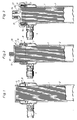
- Fig 1-3 are showing one end of an apparatus according to the present invention during three different phases of its manufacturing.
- a bundle of hollow fibers 1 is shown in a housing 2 before the casting of the end walls 3, shown in fig 2 and 3.
- the housing is provided with an inlet and/or outlet 4 intended for a first fluid.
- a similar inlet and/or outlet may be arranged at the other end of the device (not shown).
- the bundle of hollow fibers 1 is supported by a restricted part 5 of a ring 6 arranged in an expanded part 7 of the housing 2.
- the ring 6 is arranged in a groove 8 in the expanded part 7.
- At its inside the ring 6 is provided with an inwardly extending flange 9 which is shown to reach to a point near the bundle of hollow fibers. Alternatively, it may reach up to the outermost hollow fibers in order to provide a secondary support for the bundle.
- the ring 6 has as mentioned above a low adhesive capacity as regards the material of the end walls 3. It may for instance be made of polypropylene when the end walls are made of polyurethane which is a material commonly used for said end walls. Alternatively, the ring 6 may be made of polyethylene, preferably LDPE, a material which is easier to cut, or Teflon (polytetrafluorethylene), a material having a very low adhesive capacity as regards most other materials.
- a mould 10 has been provided in that the ring 6 has been completed with a lid 11 having an inlet 12 for the end wall material.
- an end surface 13 has been provided by a cutting through the bundle of hollow fibers 1, the end wall 3, the ring 6, and the expanded part 7 of the housing 2.
- the apparatus has thereafter been provided with a lid 14 with an inlet and/or outlet 15 intended for a second fluid which may be fed through the fibers to a similar inlet and/or outlet 15 arranged at the opposite end of the apparatus (not shown).
- a sealing ring 17 has therefore been provided between the lid 14 and the end surface 13 in order to provide an effective seal between the two fluids involved, i e the fluids inside and outside the hollow fibers. It is to be observed that the gap 16 is not necessary. In practice it may be enough with a reduction of the attachment between the endwall 3 and the ring 6. In order to prevent leakage the lid 14 is preferably tightly welded to the outer surface of the expanded part 7 of the housing. Other types of sealings are, however, possible.
- Fig 4-6 are showing a second embodiment of the apparatus according to the present invention. Many details are identical or similar to those shown in fig 1-3 and have therefore been given the same reference numerals, but with the addition of a .
- the apparatus shown is built up of a bundle of hollow fibers 1a in a housing 2a having an expanded part 7a.
- a slightly modified ring 6a is inserted in a groove 8a in said expanded part 7a.
- This ring 6a is in the same way as the ring 6 provided with a restricted part 5a supporting the bundle of hollow fibers 1a.
- An inlet 4a corresponds to the inlet 4.
- the main difference between the embodiment according to fig 4-6 and the above described embodiment is a number of fingers or tongues 18a arranged in the expanded part 7a of the housing 2a. Said fingers or tongues 18a are made as integral extensions of the inner wall of the housing 2a.
- ring 6a has been completed with a lid 11a with an opening 12a for the casting material for the end walls 3a.
- the fingers or tongues 18a are, as can be seen in this figure, partly embedded in said end walls 3a, providing a support for said end walls 3a in the longitudinal direction of the housing 2a.
- the bundle of hollow fibers 1a, the end wall 3a, the ring 6a and the expanded part 7a of the housing 2a have been cut, providing an end surface 13a.
- the apparatus has furthermore been provided with a lid 14a with an inlet and/or outlet 15a and with a sealing ring 17a.
- Fig 7-9 and 9a are showing a preferred third embodiment of the apparatus according to the present invention. Many of the details shown are idential to or similar to the details of fig 1-6 and have therefore been given the same reference numerals, but with the addition of b .
- a bundle of hollow fibers 1b is arranged in a housing 2b provided with an expanded part 7b with an inlet and/or outlet 4b.
- a first ring 6b similar to the ring 6 is arranged in a groove 8b in the expanded part 7b of the housing 2b.
- the ring 6b is provided with an inner flange 9b.
- the main difference between the embodiment described in the fig 7-9 and 9a and the embodiment shown in fig 1-3 is a second ring 19b arranged partly outside the expanded part 7b of the housing 2b.
- Said second ring 19b is provided on one hand with a restricted part 5b corresponding to the part 5 of the ring 6 and on the other hand with an inner longitudinal extending flange 20b intended to be partly embedded in the end wall 3b.
- the ring 19b has been provided with a lid 11b with an opening 12b for the feeding of the casting material for the end walls 3b.
- the ring 6b does not extend up to the end surface 13b an attachment and therefore a sealing is provided between the material of the end wall 3b and the inside of the expanded part 7b of the housing 2b.
- the lid 14b does therefore not have to be tightly attached to the outside wall of the expanded part 7b of the housing 2b. It may for instance be attached to the housing 2b by means of a thread arranged between the lid 14b and the expanded part 7b.
- the present invention relates also to a method of manufacturing a diffusion and/or filtration apparatus of the kind described in for instance fig 1-3, i e including a housing 2 consisting of a cylindrical open ended main part closed by two endcaps 14 and being provided with an inlet 15 and an outlet (not shown) for a first fluid and at least one outlet 4 for a second fluid, said first fluid being adapted to flow through the fibers 1 of a bundle of semipermeable hollow fibers arranged between two end walls 3 within the housing 2 and said second fluid being adapted to be removed from the space outside the fibers 1 through said at least one outlet 4 for the second fluid, the ends of the hollow fibers 1 being moulded into said end walls 3 and opened by a cutting.
- the method according to the invention is characterized in that said bundle of semipermeable hollow fibers 1 is arranged in said cylindrical open ended main part of the housing 2, supported by a ring 6 having a low adhesive capacity as regards the material of the end walls 3, said ring 6 being extended outside the open ends of the hollow fibers 1, serving as an inlet and/or outlet for a flushing fluid for the flushing of the inside and the outside of the fibers 1 and in that said ring 6 thereafter is used as a part of a mould for moulding said end walls 3 whereafter it is cut together with the fibers 1 in order to open the fiber ends, whereupon the apparatus finally is provided with said end caps 14.
- the invention is of course not restricted to only the embodiments and the method described above, but may be varied within the scope of the following claims.
- the housing may for instance be modified in accordance with the Swedish patent application 87.03366-8, filed simultaneously with the present application. A copy of said application is therefore enclosed for information.
Abstract
Description
- The present invention relates to a diffusion and/or filtration apparatus, including a housing consisting of a cylindrical open-ended main part closed by two end caps and being provided with an inlet and an outlet for a first fluid and at least one outlet for a second fluid, said first fluid being adapted to flow through the fibres of a bundle of semipermeable hollow fibers arranged between two end walls within the housing and said second fluid being adapted to be removed from the space outside the fibers through said at least one outlet for the second fluid, the ends of the hollow fibers being moulded into said end walls and opened by a cutting.
- The invention relates furthermore to a method of manufacturing the above defined apparatus.
- Devices of the above kind are used for e g different kinds of medical treatment such as hemodialysis, hemofiltration, plasmapheresis and immunotherapy. Other fields of use are for instance dialysis in general and filtration in general, for example in connection with cleaning or desalination of sea water.
- In connection with the production of devices of the above kind each end of the housing with a bundle of fibres placed therein is normally enclosed in a casting mould to which the material for the adjacent end wall is fed in a liquid condition penetrating into and around the fibers. The penetration is so controlled by the casting that the penetration into the fibers is less than around the fibers, making it possible to open the ends of the fibers by making a cut between the surfaces restricting the two different penetration depths, respectively.
- This control may be made in different ways. Preferably it is, however, made in accordance with the method described and claimed in EP-B-O 165 478. The wall material may be fed into the device as described in the above European patent or through the other two normally existing side inlets/outlets as described in US-A-4 227 295 or US-A-4 329 229. In both cases the wall material has normally up to today been firmely attached the inside wall of the housing.
- During the curing of the wall material stresses have, however, been built into the material, which sometimes later have been released in connection with the further treatment of the device, providing unacceptable cracks in the wall. Such cracks may for instance be created in connection with the opening of the fiber ends or the flushing or sterilization of the ready made apparatus.
- An attempt to solve the above problem is described and claimed in US-A-4 334 993. The present invention relates to a different way to solve the same problems, providing at the same time additional advantages as described below.
- The present invention relates to a diffusion and/or filtration apparatus of the kind defined above, characterized in that the attachment between the moulded end walls and the housing is reduced or eliminated by a ring having a low adhesive capacity as regards the material of the end walls and in that said end walls are supported in the longitudinal direction of the housing.
- Thanks to the above defined construction the risk of cracks is essentially reduced. It may therefore even be heat-sterilized in dry condition, if you choose suitable materials for the details involved. An example of how such a heat sterilization may be carried through is described more in detail in US-A-4 609 728. From the following description it will be seen that it at the same time are no problems to provide an effective seal between the two fluids involved.
- Said longitudinal support of the end walls is preferably provided by a flange arranged on the ring. Such a flange may for instance be arranged on the inside of the ring penetrating into the perifery of the end walls. By such a construction it may also be used for supporting the fiber bundle during its treatment before the casting of the end walls.
- The ring may be supported in the longitudinal direction by the housing, preferably by being arranged in a groove in the inside wall of the housing. Instead of the above mentioned flange the ring may have another dimensionally restricted part providing a support for the bundle of hollow fibers especially before the moulding of the end walls.
- Said ring is preferably extended outside the housing in order to serve as part of the mould in connection with the moulding of the end walls and is being cut together with the fibers in connection with the opening of the fiber ends.
- By a preferred embodiment of the apparatus according to the invention a second ring may be arranged at the outer end surfaces of the end walls providing a groove in each of said end surfaces, said ring having also a low adhesive capacity as regards the material of the end walls.
- Said support in the longitudinal direction of the housing may be provided by said housing in that the end walls are provided within two expanded parts of the housing and in that the support in the longitudinal direction is provided by tongues which are integral with the housing and partly moulded into the end walls. By such a construction the ring may be given a very simple form.
- The invention relates also to a method of manufacturing an apparatus of the above defined kind. Said method is characterized in that said bundle of semipermeable hollow fibers is arranged in said cylindrical open ended main part of the housing, supported by a ring having a low adhesive capacity as regards the material of the end walls, said ring being extended outside the open ends of the hollow fibers serving as an inlet and/or outlet for a flushing fluid for the flushing of the inside and the outside of the fibers and in that said ring thereafter is used as a part of a mould for moulding said end walls, whereafter it is cut together with the fibers in order to open the fiber ends, whereupon the apparatus finally is provided with said end caps.
-
- Fig 1-3 show schematically one end of a first embodiment of the present invention at three different phases of its manufacturing.
- Fig 4-6 show in the same way a second embodiment of the present invention.
- Fig 7-9 and fig 9a show in the same way a third embodiment of the present invention.
- Fig 1-3 are showing one end of an apparatus according to the present invention during three different phases of its manufacturing.
- In fig 1 a bundle of
hollow fibers 1 is shown in ahousing 2 before the casting of theend walls 3, shown in fig 2 and 3. The housing is provided with an inlet and/oroutlet 4 intended for a first fluid. A similar inlet and/or outlet may be arranged at the other end of the device (not shown). The bundle ofhollow fibers 1 is supported by a restrictedpart 5 of aring 6 arranged in an expanded part 7 of thehousing 2. Thering 6 is arranged in agroove 8 in the expanded part 7. At its inside thering 6 is provided with an inwardly extending flange 9 which is shown to reach to a point near the bundle of hollow fibers. Alternatively, it may reach up to the outermost hollow fibers in order to provide a secondary support for the bundle. - The
ring 6 has as mentioned above a low adhesive capacity as regards the material of theend walls 3. It may for instance be made of polypropylene when the end walls are made of polyurethane which is a material commonly used for said end walls. Alternatively, thering 6 may be made of polyethylene, preferably LDPE, a material which is easier to cut, or Teflon (polytetrafluorethylene), a material having a very low adhesive capacity as regards most other materials. - In fig 2 a
mould 10 has been provided in that thering 6 has been completed with alid 11 having aninlet 12 for the end wall material. - In fig 3 an
end surface 13 has been provided by a cutting through the bundle ofhollow fibers 1, theend wall 3, thering 6, and the expanded part 7 of thehousing 2. The apparatus has thereafter been provided with a lid 14 with an inlet and/oroutlet 15 intended for a second fluid which may be fed through the fibers to a similar inlet and/oroutlet 15 arranged at the opposite end of the apparatus (not shown). - Due to the relationship between the material of the
end wall 3 and thering 6 asmall gap 16 has been provided between those two details. Asealing ring 17 has therefore been provided between the lid 14 and theend surface 13 in order to provide an effective seal between the two fluids involved, i e the fluids inside and outside the hollow fibers. It is to be observed that thegap 16 is not necessary. In practice it may be enough with a reduction of the attachment between theendwall 3 and thering 6. In order to prevent leakage the lid 14 is preferably tightly welded to the outer surface of the expanded part 7 of the housing. Other types of sealings are, however, possible. - Fig 4-6 are showing a second embodiment of the apparatus according to the present invention. Many details are identical or similar to those shown in fig 1-3 and have therefore been given the same reference numerals, but with the addition of a.
- Consequently, the apparatus shown is built up of a bundle of
hollow fibers 1a in ahousing 2a having an expandedpart 7a. In agroove 8a in said expandedpart 7a a slightly modifiedring 6a is inserted. Thisring 6a is in the same way as thering 6 provided with a restrictedpart 5a supporting the bundle ofhollow fibers 1a. Aninlet 4a corresponds to theinlet 4. - The main difference between the embodiment according to fig 4-6 and the above described embodiment is a number of fingers or
tongues 18a arranged in the expandedpart 7a of the housing 2a. Said fingers ortongues 18a are made as integral extensions of the inner wall of thehousing 2a. - In fig 5 the
ring 6a has been completed with alid 11a with anopening 12a for the casting material for theend walls 3a. The fingers ortongues 18a are, as can be seen in this figure, partly embedded in saidend walls 3a, providing a support for saidend walls 3a in the longitudinal direction of thehousing 2a. - In fig 6 the bundle of
hollow fibers 1a, theend wall 3a, thering 6a and the expandedpart 7a of thehousing 2a have been cut, providing an end surface 13a. The apparatus has furthermore been provided with a lid 14a with an inlet and/oroutlet 15a and with asealing ring 17a. - Fig 7-9 and 9a are showing a preferred third embodiment of the apparatus according to the present invention. Many of the details shown are idential to or similar to the details of fig 1-6 and have therefore been given the same reference numerals, but with the addition of b.
- Consequently, a bundle of
hollow fibers 1b is arranged in ahousing 2b provided with an expandedpart 7b with an inlet and/oroutlet 4b. Afirst ring 6b similar to thering 6 is arranged in agroove 8b in the expandedpart 7b of thehousing 2b. Thering 6b is provided with aninner flange 9b. - The main difference between the embodiment described in the fig 7-9 and 9a and the embodiment shown in fig 1-3 is a
second ring 19b arranged partly outside the expandedpart 7b of the housing 2b. Saidsecond ring 19b is provided on one hand with arestricted part 5b corresponding to thepart 5 of thering 6 and on the other hand with an inner longitudinal extendingflange 20b intended to be partly embedded in theend wall 3b. - In fig 8 the
ring 19b has been provided with alid 11b with anopening 12b for the feeding of the casting material for theend walls 3b. - In fig 9 and the enlargement shown in fig 9a a cut has been made through the expanded
part 7b of thehousing 2b, theend wall 3b, theflange 20b and the bundle ofhollow fibers 1b, providing anend surface 13b. The apparatus has thereafter been provided with a lid 14b with anopening 15b and with asealing ring 17b in the same way as the above described embodiments. - Due to the fact that the
ring 6b does not extend up to theend surface 13b an attachment and therefore a sealing is provided between the material of theend wall 3b and the inside of the expandedpart 7b of thehousing 2b. The lid 14b does therefore not have to be tightly attached to the outside wall of the expandedpart 7b of thehousing 2b. It may for instance be attached to thehousing 2b by means of a thread arranged between the lid 14b and the expandedpart 7b. - The present invention relates also to a method of manufacturing a diffusion and/or filtration apparatus of the kind described in for instance fig 1-3, i e including a
housing 2 consisting of a cylindrical open ended main part closed by two endcaps 14 and being provided with aninlet 15 and an outlet (not shown) for a first fluid and at least oneoutlet 4 for a second fluid, said first fluid being adapted to flow through thefibers 1 of a bundle of semipermeable hollow fibers arranged between twoend walls 3 within thehousing 2 and said second fluid being adapted to be removed from the space outside thefibers 1 through said at least oneoutlet 4 for the second fluid, the ends of thehollow fibers 1 being moulded into saidend walls 3 and opened by a cutting. - The method according to the invention is characterized in that said bundle of semipermeable
hollow fibers 1 is arranged in said cylindrical open ended main part of thehousing 2, supported by aring 6 having a low adhesive capacity as regards the material of theend walls 3, saidring 6 being extended outside the open ends of thehollow fibers 1, serving as an inlet and/or outlet for a flushing fluid for the flushing of the inside and the outside of thefibers 1 and in that saidring 6 thereafter is used as a part of a mould for moulding saidend walls 3 whereafter it is cut together with thefibers 1 in order to open the fiber ends, whereupon the apparatus finally is provided with said end caps 14. - All the above described figures show one end of an apparatus according to the invention. Normally the opposite end is made identical with the end shown in the drawings. This is true when for instance the apparatus is intended to be used for dialysis, a treatment which needs as well an inlet as an outlet for the dialysis liquid. If, however, the apparatus is intended to be used for filtration only it is enough to have one
outlet 4 only for the filtrate. - The invention is of course not restricted to only the embodiments and the method described above, but may be varied within the scope of the following claims. The housing may for instance be modified in accordance with the Swedish patent application 87.03366-8, filed simultaneously with the present application. A copy of said application is therefore enclosed for information.
Claims (11)
Applications Claiming Priority (2)
| Application Number | Priority Date | Filing Date | Title |
|---|---|---|---|
| SE8703368 | 1987-08-31 | ||
| SE8703368A SE454847B (en) | 1987-08-31 | 1987-08-31 | DEVICE FOR DIFFUSION AND / OR FILTERING AND PROCEDURE FOR MANUFACTURING THIS DEVICE |
Publications (2)
| Publication Number | Publication Date |
|---|---|
| EP0305687A1 true EP0305687A1 (en) | 1989-03-08 |
| EP0305687B1 EP0305687B1 (en) | 1992-04-01 |
Family
ID=20369434
Family Applications (1)
| Application Number | Title | Priority Date | Filing Date |
|---|---|---|---|
| EP88111004A Expired - Lifetime EP0305687B1 (en) | 1987-08-31 | 1988-07-09 | A diffusion and/or filtration apparatus and a method of manufacturing said apparatus |
Country Status (6)
| Country | Link |
|---|---|
| US (2) | US5053130A (en) |
| EP (1) | EP0305687B1 (en) |
| JP (1) | JP2887347B2 (en) |
| DE (1) | DE3869701D1 (en) |
| ES (1) | ES2030475T3 (en) |
| SE (1) | SE454847B (en) |
Cited By (32)
| Publication number | Priority date | Publication date | Assignee | Title |
|---|---|---|---|---|
| EP0844015A2 (en) * | 1996-11-21 | 1998-05-27 | Fresenius Medical Care Deutschland GmbH | Hollow fiber membrane separation device |
| WO2000053293A1 (en) * | 1999-03-05 | 2000-09-14 | Gambro Dialysatoren Gmbh & Co Kg | Filter with membranes of hollow fibres |
| WO2001060502A1 (en) * | 2000-02-17 | 2001-08-23 | Gambro Dialysatoren Gmbh & Co. Kg | Filter comprising membranes made of hollow fibers |
| US6497685B1 (en) | 2000-03-24 | 2002-12-24 | Baxter International Inc. | Integral intravenous chamber and filter |
| WO2003028864A1 (en) * | 2001-09-28 | 2003-04-10 | Fresenius Medical Care Deutschland Gmbh | Filter device and method for the production thereof |
| EP1340534A2 (en) * | 1996-11-21 | 2003-09-03 | Fresenius Medical Care Deutschland GmbH | Hollow fiber membrane separation device |
| EP1398047A1 (en) | 2002-09-11 | 2004-03-17 | Gambro Lundia AB | End-cap for a dialyser, dialyser and method for removing gas bubbles |
| WO2007128440A1 (en) | 2006-05-05 | 2007-11-15 | Fresenius Medical Care Deutschland Gmbh | Process and apparatus for introducing a potting composition into a filter apparatus |
| US7622041B2 (en) | 2003-04-11 | 2009-11-24 | Gambro Lundia Ab | Method for making a filter device having more than one filtration compartment |
| EP2156881A1 (en) | 2008-08-22 | 2010-02-24 | Gambro Lundia AB | Cap for a diffusion and/or filtration device |
| EP2253370A1 (en) | 2009-05-20 | 2010-11-24 | Gambro Lundia AB | Membranes having improved performance |
| EP2253369A1 (en) | 2009-05-20 | 2010-11-24 | Gambro Lundia AB | Membranes having improved performance |
| EP2253367A1 (en) | 2009-05-20 | 2010-11-24 | Gambro Lundia AB | Membranes having improved performance |
| EP2253368A1 (en) | 2009-05-20 | 2010-11-24 | Gambro Lundia AB | Membranes having improved performance |
| EP2556849A1 (en) | 2011-08-08 | 2013-02-13 | Gambro Lundia AB | Separation material |
| EP2556848A1 (en) | 2011-08-08 | 2013-02-13 | Gambro Lundia AB | Separation material comprising saccharide ligands |
| EP2567750A1 (en) | 2011-09-08 | 2013-03-13 | Gambro Lundia AB | Hollow fiber membrane |
| CN103495217A (en) * | 2013-10-22 | 2014-01-08 | 威海威高血液净化制品有限公司 | Hemodialyzer with polypropylene material outer shell and manufacturing method thereof |
| EP2735358A1 (en) | 2012-11-22 | 2014-05-28 | Gambro Lundia AB | Capillary dialyzers |
| WO2014202710A1 (en) | 2013-06-20 | 2014-12-24 | Gambro Lundia Ab | Capillary dialyzers |
| EP2845641A1 (en) | 2013-09-05 | 2015-03-11 | Gambro Lundia AB | Permselective asymmetric membranes with high molecular weight polyvinylpyrrolidone |
| EP2878362A1 (en) | 2013-12-02 | 2015-06-03 | Gambro Lundia AB | Capillary dialyzers |
| EP2939731A1 (en) | 2014-04-30 | 2015-11-04 | Gambro Lundia AB | UV-irradiated hollow fiber membranes |
| US9550019B2 (en) | 2012-06-21 | 2017-01-24 | Gambro Lundia Ab | Capillary dialyzers |
| EP3290100A1 (en) | 2016-08-31 | 2018-03-07 | Gambro Lundia AB | Diffusion and/or filtration device |
| EP3388139A1 (en) | 2017-04-13 | 2018-10-17 | Gambro Lundia AB | Optimized hemodialyzer for blood purification |
| EP3427814A1 (en) | 2014-02-06 | 2019-01-16 | Gambro Lundia AB | Hemodialyzer for blood purification |
| EP3495033A1 (en) | 2017-12-11 | 2019-06-12 | Gambro Lundia AB | Capillary dialyzer |
| US10661231B2 (en) | 2014-02-06 | 2020-05-26 | Gambro Lundia Ab | Membrane for blood purification |
| EP3669888A1 (en) | 2018-12-20 | 2020-06-24 | Gambro Lundia AB | Extracorporeal devices for methods for treating diseases associated with anti-neutrophil cytoplasmic antibodies |
| EP3838384A1 (en) | 2019-12-21 | 2021-06-23 | Gambro Lundia AB | Fiber bundle handover |
| DE102021132060A1 (en) | 2021-12-06 | 2023-06-07 | B.Braun Avitum Ag | filter module |
Families Citing this family (28)
| Publication number | Priority date | Publication date | Assignee | Title |
|---|---|---|---|---|
| SE454847B (en) * | 1987-08-31 | 1988-06-06 | Gambro Dialysatoren | DEVICE FOR DIFFUSION AND / OR FILTERING AND PROCEDURE FOR MANUFACTURING THIS DEVICE |
| SE465095B (en) * | 1988-07-07 | 1991-07-22 | Gambro Dialysatoren | SEALING INCLUDING A RING OF A FLEXIBLE MATERIAL INTENDED TO BE PRESSED BETWEEN TWO PARALLEL, PRELIMINALLY SMALL SEALING SURFACES |
| JP2553717Y2 (en) * | 1991-01-31 | 1997-11-12 | 宇部興産株式会社 | housing |
| US5211728A (en) * | 1991-09-30 | 1993-05-18 | The Dow Chemical Company | Clamshell retainer used in hollow fiber membrane devices |
| WO1993023152A1 (en) * | 1992-05-18 | 1993-11-25 | Minntech Corporation | Hollow fiber filter cartridge and method of manufacture |
| US5282964A (en) * | 1993-02-19 | 1994-02-01 | The Dow Chemical Company | Boreside feed hollow fiber membrane device |
| JPH06296834A (en) * | 1993-04-20 | 1994-10-25 | Kanegafuchi Chem Ind Co Ltd | Hollow yarn type filter |
| US6623638B2 (en) | 2001-06-01 | 2003-09-23 | Baxter International Inc. | Hemodialyzer having improved dialysate perfusion |
| US20030075498A1 (en) * | 2001-06-01 | 2003-04-24 | Watkins Randolph H. | Hemodialyzer headers |
| US7297270B2 (en) * | 2003-04-04 | 2007-11-20 | Chf Solutions, Inc. | Hollow fiber filter for extracorporeal blood circuit |
| AU2003252270A1 (en) | 2003-05-30 | 2005-01-21 | Lattice Technology, Inc. | 3-dimensional graphics data display device |
| DE602004023304D1 (en) * | 2003-08-25 | 2009-11-05 | Pall Corp | FILTER DEVICE |
| KR100453329B1 (en) * | 2004-03-08 | 2004-10-21 | 주식회사 나노엔텍 | Fine filtering apparatus controllable packing density using flexible fiber |
| US20100096311A1 (en) * | 2004-10-28 | 2010-04-22 | Nxstage Medical, Inc | Blood treatment dialyzer/filter design to trap entrained air in a fluid circuit |
| DE102005043321A1 (en) * | 2005-09-12 | 2007-03-22 | Fresenius Medical Care Deutschland Gmbh | Hollow fiber membrane separation device |
| US20070102340A1 (en) * | 2005-10-27 | 2007-05-10 | Nxstage Medical, Inc. | Blood treatment filter and method of manufacturing |
| JP5399233B2 (en) * | 2006-03-20 | 2014-01-29 | ラサーク | Fluid connector |
| JP5769418B2 (en) | 2007-08-31 | 2015-08-26 | ザ リージェンツ オブ ザ ユニバーシティ オブ ミシガン | Selective cell adsorption removal apparatus and related method |
| AU2011315839B2 (en) | 2010-10-15 | 2016-02-18 | Seastar Medical Inc. | Cytopheresic cartridge and use thereof |
| WO2013106109A1 (en) | 2012-01-09 | 2013-07-18 | Humes, H., David | Cartridge and method for increasing myocardial function |
| CN105307757B (en) * | 2013-06-12 | 2017-12-15 | 赢创纤维有限公司 | Film cartridge system |
| EP3053639B1 (en) * | 2013-09-30 | 2022-07-27 | Toray Industries, Inc. | Cartridge-type hollow fiber membrane module and method for manufacturing cartridge-type hollow fiber membrane module |
| EP3131663A2 (en) | 2014-03-29 | 2017-02-22 | Princeton Trade and Technology Inc. | Blood processing cartridges and systems, and methods for extracorporeal blood therapies |
| US10426884B2 (en) | 2015-06-26 | 2019-10-01 | Novaflux Inc. | Cartridges and systems for outside-in flow in membrane-based therapies |
| US10399040B2 (en) | 2015-09-24 | 2019-09-03 | Novaflux Inc. | Cartridges and systems for membrane-based therapies |
| DE102015015149B3 (en) | 2015-11-25 | 2017-01-26 | Serumwerk Bernburg Ag | A hollow fiber membrane filtration apparatus and method of making the same |
| EP3620228B1 (en) * | 2018-09-04 | 2022-02-09 | Gambro Lundia AB | Process for making a filtration and/or diffusion device |
| DE102020116184A1 (en) | 2020-06-18 | 2021-12-23 | Fresenius Medical Care Deutschland Gmbh | Line arrangement for a filtration system |
Citations (7)
| Publication number | Priority date | Publication date | Assignee | Title |
|---|---|---|---|---|
| GB1175689A (en) * | 1965-12-22 | 1969-12-23 | Du Pont | Method of Making Fluid Separation Units |
| FR2344262A1 (en) * | 1976-03-19 | 1977-10-14 | Organon Teknika Bv | SEPARATOR DEVICE, IN PARTICULAR FOR HEMODIALYSIS |
| FR2456536A1 (en) * | 1979-05-14 | 1980-12-12 | Cordis Dow Corp | SEPARATION ELEMENT AND DEVICE, ARTIFICIAL KIDNEY USING THE SAME, AND METHOD FOR CASTING A TUBE PLATE ONTO THE END OF A HOLLOW FIBER BEAM |
| GB2053725A (en) * | 1979-07-18 | 1981-02-11 | Baxter Travenol Lab | Sealing the ends of hollow fibre dialyzers |
| EP0046889A1 (en) * | 1980-08-28 | 1982-03-10 | Akzo GmbH | Device for the transfer of heat and material by hollow fibres |
| US4334993A (en) * | 1979-12-05 | 1982-06-15 | Baxter Travenol Laboratories, Inc. | Potted-typed seal with stress relief and method of making same |
| SE454847B (en) * | 1987-08-31 | 1988-06-06 | Gambro Dialysatoren | DEVICE FOR DIFFUSION AND / OR FILTERING AND PROCEDURE FOR MANUFACTURING THIS DEVICE |
Family Cites Families (10)
| Publication number | Priority date | Publication date | Assignee | Title |
|---|---|---|---|---|
| US4289623A (en) * | 1975-11-05 | 1981-09-15 | Extracorporeal Medical Specialties, Inc. | Hollow fiber dialysis |
| US4227295A (en) * | 1978-07-27 | 1980-10-14 | Baxter Travenol Laboratories, Inc. | Method of potting the ends of a bundle of hollow fibers positioned in a casing |
| JPS5735907A (en) * | 1980-07-15 | 1982-02-26 | Toyobo Co Ltd | Fluid separating element |
| JPS6057872B2 (en) * | 1981-11-18 | 1985-12-17 | テルモ株式会社 | Hollow fiber oxygenator with built-in heat exchanger |
| US4497104A (en) * | 1982-12-20 | 1985-02-05 | Baxter Travenol Laboratories, Inc. | Separation device manufacture |
| JPS59136104A (en) * | 1983-01-24 | 1984-08-04 | Asahi Chem Ind Co Ltd | Sealing method of hollow yarn-type module |
| US4617161A (en) * | 1983-09-06 | 1986-10-14 | Baxter Travenol Laboratories, Inc. | Method of manufacture for a dialyzer having improved side ports |
| JPS61141904A (en) * | 1984-12-17 | 1986-06-28 | Daicel Chem Ind Ltd | Hollow yarn type module |
| US4855058A (en) * | 1986-06-24 | 1989-08-08 | Hydranautics | High recovery spiral wound membrane element |
| US4744900A (en) * | 1987-04-20 | 1988-05-17 | Bratt Russell I | Reverse osmosis membrane container |
-
1987
- 1987-08-31 SE SE8703368A patent/SE454847B/en not_active IP Right Cessation
-
1988
- 1988-07-09 ES ES198888111004T patent/ES2030475T3/en not_active Expired - Lifetime
- 1988-07-09 DE DE8888111004T patent/DE3869701D1/en not_active Expired - Lifetime
- 1988-07-09 EP EP88111004A patent/EP0305687B1/en not_active Expired - Lifetime
- 1988-08-26 US US07/237,504 patent/US5053130A/en not_active Expired - Lifetime
- 1988-08-30 JP JP63216191A patent/JP2887347B2/en not_active Expired - Lifetime
-
1991
- 1991-03-13 US US07/668,629 patent/US5072498A/en not_active Expired - Lifetime
Patent Citations (7)
| Publication number | Priority date | Publication date | Assignee | Title |
|---|---|---|---|---|
| GB1175689A (en) * | 1965-12-22 | 1969-12-23 | Du Pont | Method of Making Fluid Separation Units |
| FR2344262A1 (en) * | 1976-03-19 | 1977-10-14 | Organon Teknika Bv | SEPARATOR DEVICE, IN PARTICULAR FOR HEMODIALYSIS |
| FR2456536A1 (en) * | 1979-05-14 | 1980-12-12 | Cordis Dow Corp | SEPARATION ELEMENT AND DEVICE, ARTIFICIAL KIDNEY USING THE SAME, AND METHOD FOR CASTING A TUBE PLATE ONTO THE END OF A HOLLOW FIBER BEAM |
| GB2053725A (en) * | 1979-07-18 | 1981-02-11 | Baxter Travenol Lab | Sealing the ends of hollow fibre dialyzers |
| US4334993A (en) * | 1979-12-05 | 1982-06-15 | Baxter Travenol Laboratories, Inc. | Potted-typed seal with stress relief and method of making same |
| EP0046889A1 (en) * | 1980-08-28 | 1982-03-10 | Akzo GmbH | Device for the transfer of heat and material by hollow fibres |
| SE454847B (en) * | 1987-08-31 | 1988-06-06 | Gambro Dialysatoren | DEVICE FOR DIFFUSION AND / OR FILTERING AND PROCEDURE FOR MANUFACTURING THIS DEVICE |
Non-Patent Citations (2)
| Title |
|---|
| PATENT ABSTRACTS OF JAPAN, vol. 10, no. 339 (C-385)[2395], 15th November 1986; & JP-A-61 141 904 (DAICEL CHEM. IND. LTD) 28-06-1986 * |
| PATENT ABSTRACTS OF JAPAN, vol. 8, no. 255 (C-253)[1692], 21st November 1984; & JP-A-59 136 104 (ASAHI KASEI KOGYO K.K.) 04-08-1984 * |
Cited By (64)
| Publication number | Priority date | Publication date | Assignee | Title |
|---|---|---|---|---|
| EP1340534A3 (en) * | 1996-11-21 | 2003-10-08 | Fresenius Medical Care Deutschland GmbH | Hollow fiber membrane separation device |
| EP0844015A3 (en) * | 1996-11-21 | 1998-07-08 | Fresenius Medical Care Deutschland GmbH | Hollow fiber membrane separation device |
| US6074559A (en) * | 1996-11-21 | 2000-06-13 | Fresenius Medical Care Deutschland Gmbh | Filter device having a hollow fiber bundle and associated sealing devices |
| EP1530996A3 (en) * | 1996-11-21 | 2005-05-25 | Fresenius Medical Care Deutschland GmbH | Hollow fiber membrane separation device |
| EP1530996A2 (en) * | 1996-11-21 | 2005-05-18 | Fresenius Medical Care Deutschland GmbH | Hollow fiber membrane separation device |
| US6426002B1 (en) | 1996-11-21 | 2002-07-30 | Fresenius Medical Care Deutschland Gmbh | Filter device |
| US6776909B2 (en) | 1996-11-21 | 2004-08-17 | Fresenius Medical Care Deutschland Gmbh | Filter device |
| EP0844015A2 (en) * | 1996-11-21 | 1998-05-27 | Fresenius Medical Care Deutschland GmbH | Hollow fiber membrane separation device |
| EP1340534A2 (en) * | 1996-11-21 | 2003-09-03 | Fresenius Medical Care Deutschland GmbH | Hollow fiber membrane separation device |
| WO2000053293A1 (en) * | 1999-03-05 | 2000-09-14 | Gambro Dialysatoren Gmbh & Co Kg | Filter with membranes of hollow fibres |
| WO2001060502A1 (en) * | 2000-02-17 | 2001-08-23 | Gambro Dialysatoren Gmbh & Co. Kg | Filter comprising membranes made of hollow fibers |
| US6497685B1 (en) | 2000-03-24 | 2002-12-24 | Baxter International Inc. | Integral intravenous chamber and filter |
| WO2003028864A1 (en) * | 2001-09-28 | 2003-04-10 | Fresenius Medical Care Deutschland Gmbh | Filter device and method for the production thereof |
| EP1398047A1 (en) | 2002-09-11 | 2004-03-17 | Gambro Lundia AB | End-cap for a dialyser, dialyser and method for removing gas bubbles |
| US7622041B2 (en) | 2003-04-11 | 2009-11-24 | Gambro Lundia Ab | Method for making a filter device having more than one filtration compartment |
| US7790029B2 (en) | 2003-04-11 | 2010-09-07 | Gambro Lundia Ab | Filter device having more than one filtration compartment |
| WO2007128440A1 (en) | 2006-05-05 | 2007-11-15 | Fresenius Medical Care Deutschland Gmbh | Process and apparatus for introducing a potting composition into a filter apparatus |
| US8215261B2 (en) | 2006-05-05 | 2012-07-10 | Fresenius Medical Care Deutschland Gmbh | Process and apparatus for introducing a potting composition into a filter apparatus |
| EP2156881A1 (en) | 2008-08-22 | 2010-02-24 | Gambro Lundia AB | Cap for a diffusion and/or filtration device |
| US8387804B2 (en) | 2008-08-22 | 2013-03-05 | Gambro Lundia Ab | Diffusion and/or filtration device |
| US8827087B2 (en) | 2009-05-20 | 2014-09-09 | Gambro Lundia Ab | Membranes having improved performance |
| EP2253369A1 (en) | 2009-05-20 | 2010-11-24 | Gambro Lundia AB | Membranes having improved performance |
| EP2253367A1 (en) | 2009-05-20 | 2010-11-24 | Gambro Lundia AB | Membranes having improved performance |
| EP2253370A1 (en) | 2009-05-20 | 2010-11-24 | Gambro Lundia AB | Membranes having improved performance |
| US8771516B2 (en) | 2009-05-20 | 2014-07-08 | Gambro Lundia Ab | Membranes having improved performance |
| EP2253368A1 (en) | 2009-05-20 | 2010-11-24 | Gambro Lundia AB | Membranes having improved performance |
| EP2556848A1 (en) | 2011-08-08 | 2013-02-13 | Gambro Lundia AB | Separation material comprising saccharide ligands |
| WO2013020967A1 (en) | 2011-08-08 | 2013-02-14 | Gambro Lundia Ab | Separation material |
| US9844621B2 (en) | 2011-08-08 | 2017-12-19 | Gambro Lundia Ab | Separation material |
| WO2013020964A1 (en) | 2011-08-08 | 2013-02-14 | Gambro Lundia Ab | Separation material comprising saccharide ligands |
| US9259710B2 (en) | 2011-08-08 | 2016-02-16 | Gambro Lunia AB | Separation material comprising saccharide ligands |
| EP2556849A1 (en) | 2011-08-08 | 2013-02-13 | Gambro Lundia AB | Separation material |
| EP2567750A1 (en) | 2011-09-08 | 2013-03-13 | Gambro Lundia AB | Hollow fiber membrane |
| WO2013034611A1 (en) | 2011-09-08 | 2013-03-14 | Gambro Lundia Ab | Hollow fiber membrane |
| US9550019B2 (en) | 2012-06-21 | 2017-01-24 | Gambro Lundia Ab | Capillary dialyzers |
| EP2735358A1 (en) | 2012-11-22 | 2014-05-28 | Gambro Lundia AB | Capillary dialyzers |
| WO2014202710A1 (en) | 2013-06-20 | 2014-12-24 | Gambro Lundia Ab | Capillary dialyzers |
| US10022481B2 (en) | 2013-06-20 | 2018-07-17 | Gambro Lundia Ab | Capillary dialyzers |
| US10188991B2 (en) | 2013-09-05 | 2019-01-29 | Gambro Lundia Ab | Permselective asymmetric membranes |
| EP2845641A1 (en) | 2013-09-05 | 2015-03-11 | Gambro Lundia AB | Permselective asymmetric membranes with high molecular weight polyvinylpyrrolidone |
| CN103495217B (en) * | 2013-10-22 | 2016-03-16 | 威海威高血液净化制品有限公司 | A kind of hemodialyzer of polypropylene material shell and manufacture method thereof |
| CN103495217A (en) * | 2013-10-22 | 2014-01-08 | 威海威高血液净化制品有限公司 | Hemodialyzer with polypropylene material outer shell and manufacturing method thereof |
| EP2878362A1 (en) | 2013-12-02 | 2015-06-03 | Gambro Lundia AB | Capillary dialyzers |
| US11666869B2 (en) | 2014-02-06 | 2023-06-06 | Gambro Lundia Ab | Hemodialyzer for blood purification |
| US10661230B2 (en) | 2014-02-06 | 2020-05-26 | Gambro Lundia Ab | Hemodialyzer for blood purification |
| US11666868B2 (en) | 2014-02-06 | 2023-06-06 | Gambro Lundia Ab | Membrane for blood purification |
| US11273416B2 (en) | 2014-02-06 | 2022-03-15 | Gambro Lundia Ab | Membrane for blood purification |
| EP3427814A1 (en) | 2014-02-06 | 2019-01-16 | Gambro Lundia AB | Hemodialyzer for blood purification |
| US11273417B2 (en) | 2014-02-06 | 2022-03-15 | Gambro Lundia Ab | Hemodialyzer for blood purification |
| US10661231B2 (en) | 2014-02-06 | 2020-05-26 | Gambro Lundia Ab | Membrane for blood purification |
| EP2939731A1 (en) | 2014-04-30 | 2015-11-04 | Gambro Lundia AB | UV-irradiated hollow fiber membranes |
| WO2018041858A1 (en) | 2016-08-31 | 2018-03-08 | Gambro Lundia Ab | Diffusion and/or filtration device |
| US11426698B2 (en) | 2016-08-31 | 2022-08-30 | Gambro Lundia Ab | Diffusion and/or filtration device |
| EP3290100A1 (en) | 2016-08-31 | 2018-03-07 | Gambro Lundia AB | Diffusion and/or filtration device |
| WO2018188973A1 (en) | 2017-04-13 | 2018-10-18 | Gambro Lundia Ab | Optimized hemodialyzer for blood purification |
| EP3388139A1 (en) | 2017-04-13 | 2018-10-17 | Gambro Lundia AB | Optimized hemodialyzer for blood purification |
| WO2019115439A1 (en) | 2017-12-11 | 2019-06-20 | Gambro Lundia Ab | Capillary dialyzer |
| EP3495033A1 (en) | 2017-12-11 | 2019-06-12 | Gambro Lundia AB | Capillary dialyzer |
| EP3669888A1 (en) | 2018-12-20 | 2020-06-24 | Gambro Lundia AB | Extracorporeal devices for methods for treating diseases associated with anti-neutrophil cytoplasmic antibodies |
| WO2020127969A1 (en) | 2018-12-20 | 2020-06-25 | Gambro Lundia Ab | Extracorporeal devices for methods for treating diseases associated with anti-neutrophil cytoplasmic antibodies |
| EP3838384A1 (en) | 2019-12-21 | 2021-06-23 | Gambro Lundia AB | Fiber bundle handover |
| WO2021123406A1 (en) | 2019-12-21 | 2021-06-24 | Gambro Lundia Ab | Fiber bundle handover |
| DE102021132060A1 (en) | 2021-12-06 | 2023-06-07 | B.Braun Avitum Ag | filter module |
| WO2023104739A1 (en) | 2021-12-06 | 2023-06-15 | B. Braun Avitum Ag | Filter module |
Also Published As
| Publication number | Publication date |
|---|---|
| JP2887347B2 (en) | 1999-04-26 |
| EP0305687B1 (en) | 1992-04-01 |
| US5053130A (en) | 1991-10-01 |
| SE454847B (en) | 1988-06-06 |
| ES2030475T3 (en) | 1992-11-01 |
| US5072498A (en) | 1991-12-17 |
| SE8703368D0 (en) | 1987-08-31 |
| JPS6470107A (en) | 1989-03-15 |
| DE3869701D1 (en) | 1992-05-07 |
Similar Documents
| Publication | Publication Date | Title |
|---|---|---|
| EP0305687A1 (en) | A diffusion and/or filtration apparatus and a method of manufacturing said apparatus | |
| KR100382012B1 (en) | Hollow fiber membrane cartridge | |
| EP0165478B1 (en) | A method of producing a device including a bundle of hollow fibers | |
| EP0525317B1 (en) | An apparatus for effecting mass and/or heat transfer | |
| US6426002B1 (en) | Filter device | |
| EP0102539B1 (en) | A hollow thread device for removing waste material in the blood and a process of manufacture thereof | |
| JP2618820B2 (en) | Hollow fiber filter cartridge and manufacturing method | |
| US5938940A (en) | In-line liquid filtration device and method useable for blood and blood products | |
| KR101131676B1 (en) | Filter device having at least two filtration compartments filtering more than one fluid | |
| CA1089370A (en) | Hollow fiber permeability apparatus | |
| US5139669A (en) | Apparatus with hollow fibres | |
| EP0181470A2 (en) | Material transfer apparatus of hollow fiber type | |
| US4724900A (en) | Apparatus for effecting mass and/or heat transfer | |
| EP0036926A1 (en) | A device for the diffusion of substances between two fluids via semipermeable membranes | |
| EP0076422A2 (en) | Filtering device | |
| WO2000053293A1 (en) | Filter with membranes of hollow fibres | |
| EP0305672A1 (en) | A diffusion and/or filtration apparatus, a blank for the main part of the housing intended for said apparatus and a method of manufacturing the apparatus | |
| US20090050556A1 (en) | Filter device | |
| JPS61293471A (en) | Substance and/or heat exchanger and its production and hollow yarn bundle | |
| EP0058275A1 (en) | Hollow fiber artificial kidney | |
| JPH0140631B2 (en) | ||
| JPS6068007A (en) | Fluid separating apparatus | |
| JPS61240964A (en) | Body fluid treating device and its production | |
| JPH01284305A (en) | Production of hollow fiber membrane filter module | |
| CN117897182A (en) | Multi-piece dialyzer |
Legal Events
| Date | Code | Title | Description |
|---|---|---|---|
| PUAI | Public reference made under article 153(3) epc to a published international application that has entered the european phase |
Free format text: ORIGINAL CODE: 0009012 |
|
| AK | Designated contracting states |
Kind code of ref document: A1 Designated state(s): BE CH DE ES FR GB IT LI NL |
|
| 17P | Request for examination filed |
Effective date: 19890812 |
|
| RAP1 | Party data changed (applicant data changed or rights of an application transferred) |
Owner name: GAMBRO DIALYSATOREN GMBH & CO. KG |
|
| 17Q | First examination report despatched |
Effective date: 19910313 |
|
| GRAA | (expected) grant |
Free format text: ORIGINAL CODE: 0009210 |
|
| ITF | It: translation for a ep patent filed |
Owner name: BARZANO' E ZANARDO MILANO S.P.A. |
|
| AK | Designated contracting states |
Kind code of ref document: B1 Designated state(s): BE CH DE ES FR GB IT LI NL |
|
| REF | Corresponds to: |
Ref document number: 3869701 Country of ref document: DE Date of ref document: 19920507 |
|
| ET | Fr: translation filed | ||
| REG | Reference to a national code |
Ref country code: ES Ref legal event code: FG2A Ref document number: 2030475 Country of ref document: ES Kind code of ref document: T3 |
|
| PLBE | No opposition filed within time limit |
Free format text: ORIGINAL CODE: 0009261 |
|
| STAA | Information on the status of an ep patent application or granted ep patent |
Free format text: STATUS: NO OPPOSITION FILED WITHIN TIME LIMIT |
|
| 26N | No opposition filed | ||
| REG | Reference to a national code |
Ref country code: GB Ref legal event code: IF02 |
|
| PGFP | Annual fee paid to national office [announced via postgrant information from national office to epo] |
Ref country code: NL Payment date: 20030619 Year of fee payment: 16 |
|
| PGFP | Annual fee paid to national office [announced via postgrant information from national office to epo] |
Ref country code: BE Payment date: 20030811 Year of fee payment: 16 |
|
| PG25 | Lapsed in a contracting state [announced via postgrant information from national office to epo] |
Ref country code: BE Free format text: LAPSE BECAUSE OF NON-PAYMENT OF DUE FEES Effective date: 20040731 |
|
| BERE | Be: lapsed |
Owner name: *GAMBRO DIALYSATOREN G.M.B.H. & CO. K.G. Effective date: 20040731 |
|
| PG25 | Lapsed in a contracting state [announced via postgrant information from national office to epo] |
Ref country code: NL Free format text: LAPSE BECAUSE OF NON-PAYMENT OF DUE FEES Effective date: 20050201 |
|
| NLV4 | Nl: lapsed or anulled due to non-payment of the annual fee |
Effective date: 20050201 |
|
| REG | Reference to a national code |
Ref country code: CH Ref legal event code: PFA Owner name: GAMBRO DIALYSATOREN GMBH Free format text: GAMBRO DIALYSATOREN GMBH & CO. KG#ERMELESSTRASSE 76#HECHINGEN (DE) -TRANSFER TO- GAMBRO DIALYSATOREN GMBH#HOLGER-CRAFOORD STRASSE 26#72379 HECHINGEN (DE) |
|
| REG | Reference to a national code |
Ref country code: FR Ref legal event code: CD |
|
| REG | Reference to a national code |
Ref country code: CH Ref legal event code: PVP |
|
| REG | Reference to a national code |
Ref country code: FR Ref legal event code: GC |
|
| REG | Reference to a national code |
Ref country code: GB Ref legal event code: 732E |
|
| PGFP | Annual fee paid to national office [announced via postgrant information from national office to epo] |
Ref country code: ES Payment date: 20070713 Year of fee payment: 20 |
|
| PGFP | Annual fee paid to national office [announced via postgrant information from national office to epo] |
Ref country code: DE Payment date: 20070731 Year of fee payment: 20 |
|
| PGFP | Annual fee paid to national office [announced via postgrant information from national office to epo] |
Ref country code: GB Payment date: 20070618 Year of fee payment: 20 Ref country code: CH Payment date: 20070709 Year of fee payment: 20 |
|
| BERE | Be: lapsed |
Owner name: *GAMBRO DIALYSATOREN G.M.B.H. & CO. K.G. Effective date: 20040731 |
|
| PGFP | Annual fee paid to national office [announced via postgrant information from national office to epo] |
Ref country code: IT Payment date: 20070713 Year of fee payment: 20 |
|
| PGFP | Annual fee paid to national office [announced via postgrant information from national office to epo] |
Ref country code: FR Payment date: 20070706 Year of fee payment: 20 |
|
| REG | Reference to a national code |
Ref country code: CH Ref legal event code: PFA Owner name: GAMBRO DIALYSATOREN GMBH Free format text: GAMBRO DIALYSATOREN GMBH#HOLGER-CRAFOORD STRASSE 26#72379 HECHINGEN (DE) -TRANSFER TO- GAMBRO DIALYSATOREN GMBH#HOLGER-CRAFOORD STRASSE 26#72379 HECHINGEN (DE) |
|
| REG | Reference to a national code |
Ref country code: GB Ref legal event code: PE20 Expiry date: 20080708 |
|
| REG | Reference to a national code |
Ref country code: CH Ref legal event code: PL |
|
| REG | Reference to a national code |
Ref country code: ES Ref legal event code: FD2A Effective date: 20080710 |
|
| PG25 | Lapsed in a contracting state [announced via postgrant information from national office to epo] |
Ref country code: GB Free format text: LAPSE BECAUSE OF EXPIRATION OF PROTECTION Effective date: 20080708 |
|
| PG25 | Lapsed in a contracting state [announced via postgrant information from national office to epo] |
Ref country code: ES Free format text: LAPSE BECAUSE OF EXPIRATION OF PROTECTION Effective date: 20080710 |