EP0306243A2 - Optical attenuator - Google Patents
Optical attenuator Download PDFInfo
- Publication number
- EP0306243A2 EP0306243A2 EP88307963A EP88307963A EP0306243A2 EP 0306243 A2 EP0306243 A2 EP 0306243A2 EP 88307963 A EP88307963 A EP 88307963A EP 88307963 A EP88307963 A EP 88307963A EP 0306243 A2 EP0306243 A2 EP 0306243A2
- Authority
- EP
- European Patent Office
- Prior art keywords
- fibre
- incident
- face
- optical attenuator
- end faces
- Prior art date
- Legal status (The legal status is an assumption and is not a legal conclusion. Google has not performed a legal analysis and makes no representation as to the accuracy of the status listed.)
- Withdrawn
Links
Images


Classifications
-
- G—PHYSICS
- G02—OPTICS
- G02B—OPTICAL ELEMENTS, SYSTEMS OR APPARATUS
- G02B6/00—Light guides; Structural details of arrangements comprising light guides and other optical elements, e.g. couplings
- G02B6/24—Coupling light guides
- G02B6/36—Mechanical coupling means
- G02B6/38—Mechanical coupling means having fibre to fibre mating means
- G02B6/3807—Dismountable connectors, i.e. comprising plugs
- G02B6/3873—Connectors using guide surfaces for aligning ferrule ends, e.g. tubes, sleeves, V-grooves, rods, pins, balls
- G02B6/3874—Connectors using guide surfaces for aligning ferrule ends, e.g. tubes, sleeves, V-grooves, rods, pins, balls using tubes, sleeves to align ferrules
- G02B6/3875—Floatingly supported sleeves
-
- G—PHYSICS
- G02—OPTICS
- G02B—OPTICAL ELEMENTS, SYSTEMS OR APPARATUS
- G02B6/00—Light guides; Structural details of arrangements comprising light guides and other optical elements, e.g. couplings
- G02B6/24—Coupling light guides
- G02B6/26—Optical coupling means
- G02B6/262—Optical details of coupling light into, or out of, or between fibre ends, e.g. special fibre end shapes or associated optical elements
-
- G—PHYSICS
- G02—OPTICS
- G02B—OPTICAL ELEMENTS, SYSTEMS OR APPARATUS
- G02B6/00—Light guides; Structural details of arrangements comprising light guides and other optical elements, e.g. couplings
- G02B6/24—Coupling light guides
- G02B6/26—Optical coupling means
- G02B6/264—Optical coupling means with optical elements between opposed fibre ends which perform a function other than beam splitting
- G02B6/266—Optical coupling means with optical elements between opposed fibre ends which perform a function other than beam splitting the optical element being an attenuator
-
- G—PHYSICS
- G02—OPTICS
- G02B—OPTICAL ELEMENTS, SYSTEMS OR APPARATUS
- G02B6/00—Light guides; Structural details of arrangements comprising light guides and other optical elements, e.g. couplings
- G02B6/24—Coupling light guides
- G02B6/36—Mechanical coupling means
- G02B6/38—Mechanical coupling means having fibre to fibre mating means
- G02B6/3807—Dismountable connectors, i.e. comprising plugs
- G02B6/3833—Details of mounting fibres in ferrules; Assembly methods; Manufacture
- G02B6/3846—Details of mounting fibres in ferrules; Assembly methods; Manufacture with fibre stubs
-
- G—PHYSICS
- G02—OPTICS
- G02B—OPTICAL ELEMENTS, SYSTEMS OR APPARATUS
- G02B6/00—Light guides; Structural details of arrangements comprising light guides and other optical elements, e.g. couplings
- G02B6/24—Coupling light guides
- G02B6/36—Mechanical coupling means
- G02B6/38—Mechanical coupling means having fibre to fibre mating means
- G02B6/3807—Dismountable connectors, i.e. comprising plugs
- G02B6/3869—Mounting ferrules to connector body, i.e. plugs
-
- G—PHYSICS
- G02—OPTICS
- G02B—OPTICAL ELEMENTS, SYSTEMS OR APPARATUS
- G02B6/00—Light guides; Structural details of arrangements comprising light guides and other optical elements, e.g. couplings
- G02B6/24—Coupling light guides
- G02B6/36—Mechanical coupling means
- G02B6/38—Mechanical coupling means having fibre to fibre mating means
- G02B6/3807—Dismountable connectors, i.e. comprising plugs
- G02B6/381—Dismountable connectors, i.e. comprising plugs of the ferrule type, e.g. fibre ends embedded in ferrules, connecting a pair of fibres
- G02B6/3818—Dismountable connectors, i.e. comprising plugs of the ferrule type, e.g. fibre ends embedded in ferrules, connecting a pair of fibres of a low-reflection-loss type
- G02B6/3822—Dismountable connectors, i.e. comprising plugs of the ferrule type, e.g. fibre ends embedded in ferrules, connecting a pair of fibres of a low-reflection-loss type with beveled fibre ends
-
- G—PHYSICS
- G02—OPTICS
- G02B—OPTICAL ELEMENTS, SYSTEMS OR APPARATUS
- G02B6/00—Light guides; Structural details of arrangements comprising light guides and other optical elements, e.g. couplings
- G02B6/24—Coupling light guides
- G02B6/36—Mechanical coupling means
- G02B6/38—Mechanical coupling means having fibre to fibre mating means
- G02B6/3807—Dismountable connectors, i.e. comprising plugs
- G02B6/3833—Details of mounting fibres in ferrules; Assembly methods; Manufacture
- G02B6/3863—Details of mounting fibres in ferrules; Assembly methods; Manufacture fabricated by using polishing techniques
Abstract
Description
- This invention relates to an optical attenuator, e.g. for adjusting the optical power which is incident on a detector in an optical fibre transmission.
- An optical attenuator is disclosed in the Transactions of the IE/ICE,Symposium No. 2302, 1982 which comprises first and second coaxial optical fibres which are optically coupled to each other with an air gap between their adjacent end faces. These end faces, however, are normal to the axis of the optical fibres so that there is multiple reflection therebetween, and thus where light with high coherence, such as that from a laser diode (hereinafter called LD) or the like, is incident on the fibres, a change in attenuation may arise due to a temperature change or other cause. Moreover, since the light reflected from the adjacent end faces returns to the light source, it is hard to use such an optical attenuator in a system in which such reflected light may be a problem.
- According, therefore, to the present invention, there is provided an optical attenuator comprising first and second coaxial optical fibres which are optically coupled to each other with a gap between their adjacent end faces characterised in that each of the adjacent end faces is disposed obliquely to the axis of the optical fibres.
- Preferably, each of the optical fibres, at its end remote from its said adjacent end face, is provided with a part-spherical end face.
- Preferably, at least one of the adjacent end faces has an anti-reflection coating thereon.
- Preferably, each of the said end faces is polished.
- The invention is illustrated, merely by way of example, in the accompanying drawings, in which:-
- Figure 1 is a sectional view of a first embodiment of an optical attenuator according to the present invention;
- Figure 2 is an enlarged view of a part of a second embodiment of an optical attenuator according to the present invention,
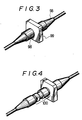
- Figure 3 is a perspective view of a fibre- connector which may be connected to an optical attenuator according to the present invention;
- Figure 4 is a perspective view showing an optical attenuator according to the present invention which is connected to the fibre connector shown in Figure 3;
- Figure 5 is a sectional view showing a third embodiment of an optical attenuator according to the present invention, and
- Figure 6 is a schematic drawing of a prior art optical attenuator.
- In Figure 6 there is shown a prior art optical attenuator. The attenuator comprises a first or incident fibre 1, an output fibre 4, and a second
optical fibre 5. Ferrules, or cladding,6, 9 and 10 is provided for holding thefibres 1, 4 and 5 respectively. Anend face 13 of the incident fibre 1 and anend face 51 of thefibre 5 are disposed adjacent to each other and are spaced apart by an air gap ℓ. Thefibres 4, 5 also have end faces 43, 52 which abut each other. - The light propagated through the incident fibre 1 is emitted into the air gap ℓ from the
end face 13. A part of the light emitted into the air gap ℓ is incident on theoptical fibre 5 from theend face 51 and is then incident on the fibre 4 by way of the end faces 52 and 43, and so is propagated. The attenuation in this case is determined by the size of the air gap ℓ between the end faces 13 and 51. Such an attenuator is disclosed in the Transactions of the IE/ICE, Symposium No. 2302, 1982. - However, the prior art optical attenuator shown in Figure 6 has the following two defects.
- That is to say, since the fibre end faces 13 and 51 are opposite to and parallel to each other and are disposed on opposite sides of the air gap ℓ, the two end faces 13 and 51 constitute a Fabry-Perot interferometer in which there is multiple reflection therebetween. Consequently, where light with high coherence, such as that from a laser diode (hereinafter called LD) or the like, is incident on the fibres, a change in attenuation may arise due to a temperature change or other cause. Moreover, since the light reflected from the adjacent end faces 13, 51 returns to the light source, the optical attenuator is difficult to use in a system (using an LD for example) in which the influence of the reflected light may be a problem.
- In Figure 1 there is therefore shown a first embodiment of an optical attenuator according to the present invention. The optical attenuator of Figure 1 comprises an incident side or
first fibre 2, and an outgoing side orsecond fibre 3. Ferrules orcladding fibres - An incident
side end face 21 of theincident side fibre 2 is polished so as to have a part-spherical surface. An outgoing side andface 22 of theincident side fibre 2 is polished so as to have a surface oblique to the axis of theincident side fibre 2,the latter being coaxial with thefibre 3. An incidentside end face 31 of theoutgoing side fibre 3, which is adjacent to theend face 22 is polished so as to have a surface oblique to the axis of theoutgoing side fibre 3. An outgoingside end face 32 of theoutgoing side fibre 3 is polished so as to have a part-spherical surface. A holding member 60 (like a slit sleeve, for example) is provided for holding theferrules incident side fibre 2 and theoutgoing side fibre 3 coaxial. A holding member 61 (like a slit sleeve for example) is provided for holding together theferrule 7 and a ferrule (not shown) corresponding to aferrule 6 illustrated in Figure 2, and thus keeping together theincident side fibre 2 and an incident fibre (not shown) corresponding to the incident fibre 1 illustrated in Figure 2 so that they are coaxial.Members member 66 is provided for preventing theholding member 61 from coming off. - Figure 2 shows part of an optical attenuator which is generally similar to that of Figure 1 but which, unlike the latter, does not have chamfered ends of the
surfaces - The optical attenuator of Figure 2 thus comprises an incident fibre 1, an outgoing fibre 4, and
ferrules - The light propagated through the incident fibre 1 is incident on the
incident side fibre 2 by way of thefibre end faces side end face 22 of theincident side fibre 2 which is polished so as to be oblique to the axis of theincident side fibre 2. A part of the light transmitted to the air gap ℓ is incident on theoutgoing side fibre 3 from the incidentside end face 31 of theoutgoing side fibre 3 which is polished so as to be oblique to the axis of thefibre 3, passes through thefibre end faces - In this case, the attenuation is determined by the size of the air gap ℓ between the outgoing
side end face 22 of theincident side fibre 2 and the incidentside end face 31 of theoutgoing side fibre 3, the angle (90°- ϑ₁) formed between the axis of theincident side fibre 2 and the outgoingside end face 22 of theincident side fibre 2, and the angle (90° - ϑ₂) formed between the axis of theoutgoing side fibre 3 and the incidentside end face 31 of theoutgoing side fibre 3. The greater the value of ℓ, ϑ₁, ϑ₂, the larger is the attenuation achieved. - Since the outgoing
side end face 22 of theincident side fibre 2 and the incidentside end face 31 of theoutgoing side fibre 3 are not parallel to each other, the end faces 22, 31 do not form a Fabry-Perot interferometer. Accordingly, multiple reflection will not arise between the outgoingside end face 22 of theincident side fibre 2 and the incidentside end face 31 of theoutgoing side 3. Further, since the outgoingside end face 22 of theincident side fibre 2 and the incidentside end face 31 of theoutgoing side fibre 3 are inclined to the axis of theincident side fibre 2 and the axis of theoutgoing side fibre 3 respectively, the light of the Fresnel reflection at the outgoingside end face 22 of theincident side fibre 2 and the incidentside end face 31 of theoutgoing side fibre 3 cannot be propagated through the optical fibre. Thus, reflections at the junction of the incident fibre 1 and theincident side fibre 2 of the optical attenuator, and also at the junction of theoutgoing side fibre 3 of the optical attenuator and the outgoing fibre 4 are minimized as each end face is polished so as to be part-spherical. - Figure 3 is a perspective view of a fibre connector, Figure 3 showing the construction before the optical attenuator of the present invention is connected thereto. The fibre connector comprises a
plug 98 and anadapter 99. Figure 4 is a perspective view showing anoptical attenuator 100 according to the present invention connected to the fibre connector of Figure 3. - Figure 5 shows another embodiment of the present invention. The Figure 5 construction is provided with
members ferrules ferrule 8 and theferrule 9 shown in Figure 2, and thus for keeping coaxial theoutgoing side fibre 3 and the outgoing fibre 4 illustrated in Figure 2. Amember 69 is provided for preventing theholding member 62 from coming off. Like reference numerals represent like parts in Figures 1 and 5. - In the embodiments described above, the adjacent end faces of the coupled fibres are polished and are oblique to the axis of the optical fibres, the adjacent end faces being disposed opposite each other to maintain a prescribed gap which is effective in preventing a situation in which the adjacent end faces can work as a Fabry-Perot interferometer, in which situation reflected light from the adjacent end faces will not be propagated through the optical fibres.
- In Figure 1, Figure 2 and Figure 5, an anti-reflection coating (AR coating) (not shown) formed by evaporation on the outgoing
side end face 22 of theincident side fibre 2 and on the incidentside end face 31 of theoutgoing side fibre 3 is effective in further decreasing the reflected light and multiple reflection between the outgoingside end face 22 of theincident side fibre 2 and the incidentside end face 31 of theoutgoing side fibre 3. - The above description refers to the case where light is incident from the incident fibre 1. However, if light is incident from the outgoing fibre 4, the attenuation remains exactly the same.
- An optical attenuator as described above thus does not cause an increase in reflected light or a degradation of optical signals due to multiple reflection of the light. It is therefore applicable to a single mode fibre, and, moreover, is cheap.
Claims (4)
Applications Claiming Priority (2)
| Application Number | Priority Date | Filing Date | Title |
|---|---|---|---|
| JP221485/87 | 1987-09-04 | ||
| JP62221485A JPS6465506A (en) | 1987-09-04 | 1987-09-04 | Optical attenuator |
Publications (2)
| Publication Number | Publication Date |
|---|---|
| EP0306243A2 true EP0306243A2 (en) | 1989-03-08 |
| EP0306243A3 EP0306243A3 (en) | 1989-12-13 |
Family
ID=16767449
Family Applications (1)
| Application Number | Title | Priority Date | Filing Date |
|---|---|---|---|
| EP88307963A Withdrawn EP0306243A3 (en) | 1987-09-04 | 1988-08-26 | Optical attenuator |
Country Status (3)
| Country | Link |
|---|---|
| US (1) | US4893889A (en) |
| EP (1) | EP0306243A3 (en) |
| JP (1) | JPS6465506A (en) |
Cited By (9)
| Publication number | Priority date | Publication date | Assignee | Title |
|---|---|---|---|---|
| EP0496593A2 (en) * | 1991-01-23 | 1992-07-29 | Nec Corporation | Terminal structure for an optical device |
| GB2257264A (en) * | 1991-07-05 | 1993-01-06 | Seiko Giken Kk | Ferrule with optical fibre having a shaped end |
| EP0967497A1 (en) * | 1998-06-16 | 1999-12-29 | Lucent Technologies Inc. | Optical adapter including a ferrule assembly |
| WO2002099486A1 (en) * | 2001-06-01 | 2002-12-12 | Adc Telecommunications, Inc. | Bulkhead adapter with optical fiber for signal attenuation |
| WO2003067289A2 (en) * | 2002-02-08 | 2003-08-14 | Schott Glas | Connecting device for connecting at least two optical waveguides, in particular optical waveguides of different refractive index |
| WO2004008211A1 (en) * | 2002-07-16 | 2004-01-22 | Tyco Electronics Raychem Nv | Optical fibre connector |
| US6866425B2 (en) | 2003-02-14 | 2005-03-15 | Adc Telecommunications, Inc. | In-line optical device with removable housing and method |
| WO2008088674A1 (en) * | 2007-01-12 | 2008-07-24 | Corning Cable Systems Llc | Non-physical contact visual fault locator coupler |
| TWI404984B (en) * | 2009-06-05 | 2013-08-11 | Protai Photonic Co Ltd | Mpo type optical fiber adapter |
Families Citing this family (22)
| Publication number | Priority date | Publication date | Assignee | Title |
|---|---|---|---|---|
| US5109468A (en) * | 1990-05-08 | 1992-04-28 | M/A-Com Light Control Systems, Inc. | Fixed value fiber optic attenuator |
| JP2633073B2 (en) * | 1990-09-07 | 1997-07-23 | 株式会社精工技研 | Variable optical attenuator |
| US5050956A (en) * | 1990-09-20 | 1991-09-24 | Hunter Associates Laboratory Inc. | Optical fiber attenuator and connecting element |
| US5136681A (en) * | 1991-07-09 | 1992-08-04 | Seikoh Giken Co., Ltd. | Optical powder attenuator of variable attenuation type |
| JPH05100117A (en) * | 1991-10-11 | 1993-04-23 | Seiko Giken:Kk | Light attenuating element and production thereof |
| US5319733A (en) * | 1992-01-02 | 1994-06-07 | Adc Telecommunications, Inc. | Variable fiber optical attenuator |
| EP0694173A1 (en) * | 1992-01-02 | 1996-01-31 | Adc Telecommunications, Inc. | Overlapping fusion attenuator |
| US5367159A (en) * | 1992-08-25 | 1994-11-22 | Methode Electronics, Inc. | Optical loopback tester with air gap attenuator |
| DE4233489A1 (en) * | 1992-10-05 | 1994-04-07 | Electronic Production Partners | Optical component |
| EP0652451B1 (en) * | 1993-11-08 | 2001-08-08 | Corning Incorporated | Planar optical waveguides with low back reflection pigtailing |
| JPH09145957A (en) * | 1995-11-20 | 1997-06-06 | Fujitsu Ltd | Optical connector |
| KR100206176B1 (en) * | 1996-12-03 | 1999-07-01 | 윤종용 | Optical attenuator and the manufacturing method thereof |
| US6012852A (en) * | 1996-12-18 | 2000-01-11 | The Whitaker Corporation | Expanded beam fiber optic connector |
| JP3311681B2 (en) * | 1998-07-07 | 2002-08-05 | 株式会社精工技研 | Variable optical attenuator with latching ratchet |
| US6311010B1 (en) | 1999-11-17 | 2001-10-30 | Telephone Services, Inc. Of Florida | Variable optical attenuator with locking mechanism |
| GB0219794D0 (en) * | 2002-08-23 | 2002-10-02 | Alcatel Optronics Uk Ltd | A variable optical attenuator |
| US7325977B2 (en) * | 2004-03-30 | 2008-02-05 | Lockheed Martin Corporation | Optical coupling |
| JP2006084498A (en) * | 2004-09-14 | 2006-03-30 | Fujikura Ltd | Optical attenuator |
| US20070196053A1 (en) * | 2006-02-17 | 2007-08-23 | Anthony Kewitsch | Isolated Fiber Optic Union Adapters |
| US7665901B2 (en) * | 2006-02-17 | 2010-02-23 | Telescent Inc. | Protective fiber optic union adapters |
| US8452152B2 (en) * | 2010-06-29 | 2013-05-28 | Juniper Networks, Inc. | Fixed attenuation air gap interface for a multimode optical fiber interconnection |
| US9557488B2 (en) | 2011-01-11 | 2017-01-31 | Corning Incorporated | Optical connector with lenses having opposing angled planar surfaces |
Citations (5)
| Publication number | Priority date | Publication date | Assignee | Title |
|---|---|---|---|---|
| JPS57161816A (en) * | 1981-03-31 | 1982-10-05 | Fujitsu Ltd | Optical connector |
| JPS5994702A (en) * | 1982-11-22 | 1984-05-31 | Nec Corp | Optical attenuator |
| JPS60133413A (en) * | 1983-12-21 | 1985-07-16 | Matsushita Electric Ind Co Ltd | Optical attenuator |
| US4666243A (en) * | 1985-03-28 | 1987-05-19 | Telefonaktiebolaget Lm Ericsson | Fibre joint with optical attenuation |
| DE3701421A1 (en) * | 1987-01-20 | 1988-07-28 | Standard Elektrik Lorenz Ag | Optical plug-type connector |
Family Cites Families (2)
| Publication number | Priority date | Publication date | Assignee | Title |
|---|---|---|---|---|
| US4384203A (en) * | 1981-05-18 | 1983-05-17 | General Electric Company | Optical fiber angle position sensor |
| US4695126A (en) * | 1985-02-11 | 1987-09-22 | Dorran Photonics, Incorporated | Method and apparatus for effecting light energy transmission with lessened reflection |
-
1987
- 1987-09-04 JP JP62221485A patent/JPS6465506A/en active Pending
-
1988
- 1988-08-26 EP EP88307963A patent/EP0306243A3/en not_active Withdrawn
- 1988-08-29 US US07/237,893 patent/US4893889A/en not_active Expired - Fee Related
Patent Citations (5)
| Publication number | Priority date | Publication date | Assignee | Title |
|---|---|---|---|---|
| JPS57161816A (en) * | 1981-03-31 | 1982-10-05 | Fujitsu Ltd | Optical connector |
| JPS5994702A (en) * | 1982-11-22 | 1984-05-31 | Nec Corp | Optical attenuator |
| JPS60133413A (en) * | 1983-12-21 | 1985-07-16 | Matsushita Electric Ind Co Ltd | Optical attenuator |
| US4666243A (en) * | 1985-03-28 | 1987-05-19 | Telefonaktiebolaget Lm Ericsson | Fibre joint with optical attenuation |
| DE3701421A1 (en) * | 1987-01-20 | 1988-07-28 | Standard Elektrik Lorenz Ag | Optical plug-type connector |
Non-Patent Citations (4)
| Title |
|---|
| ELECTRONICS LETTERS vol. 22, no. 2, January 1986, pages 110-112, Stevenage, Herts, GB; N. SUZUKI et al.: "Low insertion - and high return-loss optical connectors with spherically convex-polished end" * |
| PATENT ABSTRACTS OF JAPAN vol. 7, no. 2 (P-166)(1147), 7 January 1983; & JP-A-57 161 816 (FUJITSU K.K.) 05.10.1982 * |
| PATENT ABSTRACTS OF JAPAN vol. 8, no. 211 (P-303)(1648), 26 September 1984; & JP-A-59 094 702 (NIPPON DENKI K.K.) 31.05.1984 * |
| PATENT ABSTRACTS OF JAPAN vol. 9, no. 296 (P-407)(2019), 22 November 1985; & JP-A-60 133 413 (MATSUSHITA DENKI SANGYO K.K.) 16.07.1985 * |
Cited By (17)
| Publication number | Priority date | Publication date | Assignee | Title |
|---|---|---|---|---|
| EP0496593A2 (en) * | 1991-01-23 | 1992-07-29 | Nec Corporation | Terminal structure for an optical device |
| EP0496593A3 (en) * | 1991-01-23 | 1993-07-28 | Nec Corporation | Terminal structure for an optical device |
| GB2257264A (en) * | 1991-07-05 | 1993-01-06 | Seiko Giken Kk | Ferrule with optical fibre having a shaped end |
| DE4219049A1 (en) * | 1991-07-05 | 1993-01-07 | Seiko Giken Kk | OPTICAL CONNECTION DEVICE |
| EP0967497A1 (en) * | 1998-06-16 | 1999-12-29 | Lucent Technologies Inc. | Optical adapter including a ferrule assembly |
| US6102581A (en) * | 1998-06-16 | 2000-08-15 | Lucent Technologies Inc. | Optical adapter including a ferrule assembly |
| WO2002099486A1 (en) * | 2001-06-01 | 2002-12-12 | Adc Telecommunications, Inc. | Bulkhead adapter with optical fiber for signal attenuation |
| US6712523B2 (en) | 2001-06-01 | 2004-03-30 | Adc Telecommunications, Inc. | Bulkhead adapter with optical fiber for signal attenuation |
| WO2003067289A3 (en) * | 2002-02-08 | 2003-10-16 | Schott Glas | Connecting device for connecting at least two optical waveguides, in particular optical waveguides of different refractive index |
| WO2003067289A2 (en) * | 2002-02-08 | 2003-08-14 | Schott Glas | Connecting device for connecting at least two optical waveguides, in particular optical waveguides of different refractive index |
| US6744952B2 (en) | 2002-02-08 | 2004-06-01 | Schot Glas | Connecting device for connecting at least two optical waveguides, in particular optical waveguides of different refractive index |
| WO2004008211A1 (en) * | 2002-07-16 | 2004-01-22 | Tyco Electronics Raychem Nv | Optical fibre connector |
| US6866425B2 (en) | 2003-02-14 | 2005-03-15 | Adc Telecommunications, Inc. | In-line optical device with removable housing and method |
| WO2008088674A1 (en) * | 2007-01-12 | 2008-07-24 | Corning Cable Systems Llc | Non-physical contact visual fault locator coupler |
| US7520677B2 (en) | 2007-01-12 | 2009-04-21 | Corning Cable Systems Llc | Non-physical contact visual fault locator coupler |
| CN101600952B (en) * | 2007-01-12 | 2011-12-07 | 康宁光缆系统有限公司 | Non-physical contact visual fault locator coupler |
| TWI404984B (en) * | 2009-06-05 | 2013-08-11 | Protai Photonic Co Ltd | Mpo type optical fiber adapter |
Also Published As
| Publication number | Publication date |
|---|---|
| US4893889A (en) | 1990-01-16 |
| JPS6465506A (en) | 1989-03-10 |
| EP0306243A3 (en) | 1989-12-13 |
Similar Documents
| Publication | Publication Date | Title |
|---|---|---|
| EP0306243A2 (en) | Optical attenuator | |
| EP0192164B1 (en) | Optical coupling device | |
| US4213677A (en) | Light coupling and branching device using light focusing transmission body | |
| CA2047374C (en) | Optical fiber connecting device including attenuator | |
| US6075635A (en) | Bidirectional optical transceiver assembly | |
| US6249626B1 (en) | Multimode fiber optical power monitoring tap for optical transmission systems | |
| US4900124A (en) | Biconic optical fiber connecting device having attenuator | |
| EP0444694B1 (en) | Optical coupler | |
| JP2786322B2 (en) | Reflection reduction assembly | |
| US5796899A (en) | Bidirectional optical transceiver assembly with reduced crosstalk | |
| US5838859A (en) | Bidirectional optical transceiver assembly | |
| US4427261A (en) | Optical transmission system having reduced modal noise | |
| US5822478A (en) | Optical device with means for preventing remaining scattered light rays from being fed back to the signal line and method for fabricating it | |
| JPS6158806B2 (en) | ||
| US5066089A (en) | Arrangement for optically coupling light between an electro-optical transducer and a light waveguide | |
| US5257335A (en) | Single mode optical fiber device including a short lens optical fiber | |
| JPH01255803A (en) | Optical fixed attenuator | |
| US5011255A (en) | Holographic optical fiber coupler | |
| EP1223456B1 (en) | Low polarisation dependent loss beam splitter | |
| JPS61132911A (en) | Optical connector plug | |
| US5971627A (en) | Method for optically connecting an optical element, for example an end portion of an optical fibre, with a lens | |
| US5166514A (en) | Optical plug system for optical measuring device | |
| JPS62116905A (en) | Antireflection ferrule | |
| JPH09258061A (en) | High-stability photodetecting device | |
| JP3132855B2 (en) | Optical coupler and coupling method thereof |
Legal Events
| Date | Code | Title | Description |
|---|---|---|---|
| PUAI | Public reference made under article 153(3) epc to a published international application that has entered the european phase |
Free format text: ORIGINAL CODE: 0009012 |
|
| AK | Designated contracting states |
Kind code of ref document: A2 Designated state(s): CH DE FR GB LI |
|
| PUAL | Search report despatched |
Free format text: ORIGINAL CODE: 0009013 |
|
| AK | Designated contracting states |
Kind code of ref document: A3 Designated state(s): CH DE FR GB LI |
|
| 17P | Request for examination filed |
Effective date: 19900608 |
|
| 17Q | First examination report despatched |
Effective date: 19900829 |
|
| STAA | Information on the status of an ep patent application or granted ep patent |
Free format text: STATUS: THE APPLICATION IS DEEMED TO BE WITHDRAWN |
|
| 18D | Application deemed to be withdrawn |
Effective date: 19920512 |