EP0306966B1 - Bending magnet - Google Patents
Bending magnet Download PDFInfo
- Publication number
- EP0306966B1 EP0306966B1 EP88114762A EP88114762A EP0306966B1 EP 0306966 B1 EP0306966 B1 EP 0306966B1 EP 88114762 A EP88114762 A EP 88114762A EP 88114762 A EP88114762 A EP 88114762A EP 0306966 B1 EP0306966 B1 EP 0306966B1
- Authority
- EP
- European Patent Office
- Prior art keywords
- orbit
- circumference side
- bending
- charged particle
- outer circumference
- Prior art date
- Legal status (The legal status is an assumption and is not a legal conclusion. Google has not performed a legal analysis and makes no representation as to the accuracy of the status listed.)
- Expired - Lifetime
Links
Images


Classifications
-
- H—ELECTRICITY
- H05—ELECTRIC TECHNIQUES NOT OTHERWISE PROVIDED FOR
- H05H—PLASMA TECHNIQUE; PRODUCTION OF ACCELERATED ELECTRICALLY-CHARGED PARTICLES OR OF NEUTRONS; PRODUCTION OR ACCELERATION OF NEUTRAL MOLECULAR OR ATOMIC BEAMS
- H05H7/00—Details of devices of the types covered by groups H05H9/00, H05H11/00, H05H13/00
- H05H7/04—Magnet systems, e.g. undulators, wigglers; Energisation thereof
Description
- This invention relates to a bending magnet according to the preamble portion of
claim 1. - Such a bending magnet is disclosed in Japanese patent unexamined publication JP-A-61-80800. This example intends to generate a strong magnetic field of about 3 teslas, and has an iron core having upper and lower magnetic poles and upper and lower superconducting coils wound on the upper and lower poles, respectively. When the vertical distance between coil segments of the upper and lower coils desposed in the inner side of the orbit is h₁ and the distance between the coil segments of the upper and lower coils disposed in the outer side of the orbit is h₂, the bending magnet is divided into three areas in the direction of the orbit of charged particle beam and the superconducting coils are disposed such that the vertical distances h₁ and h₂ satisfy h₁ > h₂, h₁ = h₂ and h₁ < h₂ in the three areas, respectively. The iron core encloses the overall length of the coils. The super-conducting coils generate a strong magnetizing force by which the magnetic poles are strongly saturated.
- Thus, in the area of bending magnet where h₁ > h₂ holds, the bending magnetic field is stronger on the outer circumference side than on the inner circumference side to produce a magnetic field which causes the charged particle beam to diverge in a direction perpendicular to the orbital plane of the charged particle beam. In the area where h₁ < h₂ holds, the bending magnetic field is weaker on the outer circumference side than on the inner circumference side to produce a magnetic field which causes the charged particle beam to converge in the aforementioned direction. In the area where h₁ = h₂ holds, the magnetic field on the inner circumference side is equal to that on the outer circumference side and the bending magnetic field becomes uniform. Accordingly, the bending magnet per se is effective to converge or diverge the charged particle beam and is suitable for realization of a strongly focusing type synchrotron or storage ring removed of quadrupole magnet.
- In another prior art, the vertical distance h₁ between the inner circumference side coil segments is made to be equal to the vertical distance h₂ between the outer circumference side coil segments for the purpose of obtaining the uniform bending magnetic field. However, since, in the prior art, magnetic saturation of the magnetic poles of the iron core was not fully taken into consideration, it was difficult to obtain sufficient uniformity of the magnetic field even if the coils were disposed to satisfy h₁ = h₂ upon detailed magnetic field calculation in consideration of non-linearity of iron core and experimental study. Thus, the prior art coil arrangement is unsuitable for the bending magnet. Especially, in a synchrotron or a storage ring in which the number of bending magnets is small, one bending magnet shares a large bending angle for the charged particle beam and the magnet configuration is sectoral or semi-circular, with the result that the non-uniformity of magnetic field is aggravated. Further, the prior art suggests a coil arrangement of making the vertical distance between inner circumference side coil segments different from the vertical distance between outer circumference side coil segments for causing the magnetic field to converge or diverge but nothing about improvement of uniformity of magnetic field. In conclusion, the prior art in no way takes into account improving the uniformity of magnetic field over the overall length of the orbit of charged particle beam in the bending magnet.
- Japanese patent unexamined publications JP-A-62-186500 and JP-A-62-140400 also disclose a superconducting bending magnet, but none of these publications suggests nothing about the above problem to be solved by the present invention.
- The present invention contemplates elimination of the prior art drawbacks and has for its object to provide a bending magnet which can generate a strong and uniform bending magnetic field over the overall length of the orbit of charged particle beam even when the bending magnet has the form of a sector or semi-circle.
- According to the invention, this object is achieved by a bending magnet according to
claim 1. - Fig. 1 is a sectional view illustrating a bending magnet according to an embodiment of the invention;
- Fig. 2 is a sectional view taken on the line II - II′ of Fig. 1;
- Fig. 3 is a plan view of a storage ring employing bending magnets according to the invention;
- Fig. 4 is a sectional view illustrating a bending magnet according to another embodiment of the invention;
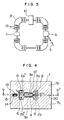
- Fig. 5 is a sectional view taken on the line V - V′ of Fig. 4; and
- Fig. 6 is a similar view to Fig. 5 illustrating still another embodiment of the invention.
- The invention will now be described by way of example with reference to the accompanying drawings.
- Figs. 1 and 2 illustrate a bending magnet according to an embodiment of the invention.
- As shown, a pair of
opposed cryostats 6 each incorporating a superconducting coil are placed in a cavity formed in acore 1 maintained at normal temperature and an upper superconductingcoil having segments superconducting coil coil having segments superconducting coil charged particle beam 5. In this embodiment, a vertical distance h₂ between thecoil segments 2a′ and 2b′ of the upper and lower superconducting coils disposed at the outer circumference side of the orbit of thecharged particle beam 5 is made to be larger than a vertical distance h₁ between thecoil segments return yoke 7b disposed at the outer circumference side of the orbit is made to be smaller than that of areturn yoke 7a disposed at the inner circumference side of the orbit so that the sectional configuration of the inner circumference side return yoke and the sectional configuration of the outer circumference side return yoke are asymmetrical with respect to the center line of the magnetic poles. Accordingly, the magnetic flux density is equally uniformed in the inner and outer circumferenceside return yokes side return yokes Magnetic poles core 1 maintained at normal temperature and the magnetic circuit comprised of thecore 1 and uppersuperconducting coil superconducting coil magnetic poles vacuum chamber 4 is disposed in the gap and thecharged particle beam 5 circulates through the vacuum chamber. - The plan configuration of the superconducting bending magnet will be better understood when explained with reference to Fig. 2.
- Fig. 2 shows a sectional structure of the bending magnet having a bending angle of 90° for the
charged particle beam 5. The bending angle may be any angle obtained by dividing 360° by an integer n which is 2 or more. However, since the configuration of the bending magnet approximates a linear bending magnet for n being large, the value of n may preferably approximate 2 or 4. - Referring to Fig. 2, the sectional configuration of the
core 1 is sectoral and thearcuate vacuum chamber 4 through which thecharged particle beam 5 circulates is disposed in the gap formed centrally of theiron core 1. The sectional configuration of each of the inner and outer circumferenceside return yokes superconducting coil super-conducting coil cryostat 6, at opposite ends of the bending magnet and the connecting portions are bent up or down so as not to interfere spatially with thevacuum chamber 4. - As described above, since in the present embodiment the configuration of the superconducting bending magnet is sectoral, the magnetic flux passing through the inner and outer circumference side return yokes can be equally uniformed over the overall length in the orbital direction of the
charged particle beam 5 by widening the vertical distance between the outer circumferenceside coil segments 2a′ and 2b′ in order to uniform the magnetic flux distribution of the bending magnetic field generated in the gap betweenmagnetic poles - Thus, the charged particle beam can be 90° bent under the influence of a strong bending magnetic field generated by the superconducting coils. An example of a storage ring using the bending magnets is illustrated in Fig. 3. Referring to Fig. 3, reference numeral 8 designates the bending magnet in accordance with the above embodiment, 9 a septum magnet by which the charged particle beam is injected, 10 a radio frequency cavity for accelerating the charged particle beam, 16 a quadrupole magnet for focus or defocus of the
charged particle beam 5, and 11 a kicker magnet which is a pulse magnet adapted to make easy the injection of thecharged particle beam 5 by slightly shifting the orbit of thecharged particle beam 5. In the example of Fig. 3, four of the bending magnets in accordance with the above embodiment are used in combination with other components to form the storage ring of thecharged particle beam 5. The storage ring using the superconducting bending magnets according to the invention to make the bending magnetic field strong can store acharged particle beam 5 having energy which is higher by an increased bending magnetic field than that stored in a storage ring of the same scale based on normal conductivity. Accordingly, by adopting the bending magnets according to the present embodiment, a synchrotron or storage ring of charged particle beam with the sectoral superconducting bending magnets can be provided by which a charged particle beam having energy which is higher than that obtained by a synchrotron or storage ring of the same scale based on normal conducting bending magnets can be accelerated or stored. - Referring to Figs. 4 and 5, a bending magnet according to another embodiment of the invention will now be described.
- This embodiment is directed to a bending magnet for an electron synchrotron or storage ring, particularly, in consideration of an application in which the accelerator is used as a synchrotron radiation (SR) source.
- As shown in Fig. 4, this embodiment differs from the Fig. 1 embodiment in that
tunnels 15 are formed in the outer circumference side return yoke vertically centrally thereof i.e. on a plane containing the orbit of charged particle beam, andguide ducts 14 forradiations 13 radiating tangentially to the orbit of acharged particle beam 12 are provided in thetunnels 15. In this embodiment, the vertical distance h₂ betweensuperconducting coil segments 2a′ and 2b′ disposed at the outer circumference side of the orbit ofcharged particle beam 12 is made to be larger than the vertical distance, h₁, betweensuperconducting coil segments magnetic poles cryostats 6 containing the upper and lower coil segments, respectively, disposed at the outer circumference side of the orbit so that theradiation guide ducts 14 can extend to the outside of thecore 1 through the gap. - The plan configuration of the bending magnet in accordance with the present embodiment will be better understood when explained with reference to Fig. 5.
- Fig. 5 shows a sectional structure of the bending magnet having a bending angle of 90° for the charged particle beam. The value of bending angle is determined similarly to the foregoing embodiment, that is, by dividing 360° by a relatively small integer which is 2 or more and may be different from 90°.
- In Fig. 5, two
radiation guide ducts 14 extend from avacuum chamber 4 disposed in the bending magnet. Theradiation guide ducts 14 pass through thetunnels 15 in the outer circumferenceside return yoke 7b tangentially to the orbit of thecharged particle beam 12 so as to extend to the outside of acore 1. The inner walls of theradiation guide duct 14 perpendicular to the charged particle orbit are parallel to the tangents of the orbit ofcharged particle beam 12 in order to decrease the amount of gas discharged from the inner wall under irradiation of theradiation 13. The number ofradiation guide ducts 14 may be three or more but must be determined so as not to lead to magnetic saturation of the outer circumferenceside return yoke 7b and to a great difference in reluctance between the inner and outer circumferenceside return yokes superconducting coil superconducting coil core 1. - The embodiments of Figs. 4 and 5, as well as Figs. 1 and 2 are all capable of generating a uniform bending magnetic field in the gap between
magnetic poles - More particularly, where the total energy of a charged particle beam is E, the rest mass of a charged particle is mo, the velocity of light is c and the rest energy of the charged particle beam is Eo (= mo C²), the Lorentz factor γ representative of the degree of generation of radiation is given by

since Eo = 511 KeV holds for an electron, the electron beam energy approximating a few hundred of MeV or more is a sufficiently high relativistic energy value to obtain γ ≳ a few thousand, and with the electron the bending magnet can be utilized for a synchrotron radiation source. But with a weighty charged particle such as a proton whose mass is about 2000 times as large as that of an electron, the radiation can not almost be generated unless a proton beam has a very high energy value. Therefore, the bending magnet in accordance with the embodiment of Figs. 1 and 2 which is removed ofradiation guide duct 14 can be utilized as a superconducting bending magnet with a sectoral core which is used with a weighty charged particle such as a proton. - A further embodiment of the invention will be described with reference to Fig. 6.
- In this embodiment of Fig. 6, five
tunnels 15 are formed in an outer circumferenceside return yoke 7b at circumferentially equi-distant intervals.Radiation guide ducts 14 are disposed in only three of the tunnels at positions which are downstream of the orbit of the chargedparticle beam 12 and from which the radiation can be guided. - This embodiment adds to the bending magnet of the embodiment shown in Figs. 4 and 5 such a feature that upstream of the orbit of the charged
particle beam 12, a plurality oftunnels 15 are provided in which no radiation guideduct 14 is disposed. Advantageously, with this construction, the cross-sectional structure of the outer circumferenceside return yoke 7b can be uniformed circumferentially to improve uniformity of the distribution of bending magnetic field in the orbital direction of the charged particle beam. - In the previously-described embodiments, values of the vertical distance h₁ between the inner circumference side
superconducting coil segments superconducting coil segments 2a′ and 2b′ are determined as will be described below. - Firstly, the vertical distance h₁ between the inner circumference side
superconducting coil segments horizontal line 20 passing the chargedparticle beam 5 and a line connecting the chargedparticle beam 5 and the center of inner circumference sidesuperconducting coil segment superconducting coil segments superconducting coil segments 2a′ and 2b′ is approximately determined through calculation by reflecting the determined vertical distance h₁ between the inner circumference sidesuperconducting coil segments coil segments - In accordance with any of the foregoing embodiments the magnetic flux in the vacuum chamber can be distributed uniformly in the radial direction of the bending magnet and over the overall length of the orbit of the charged particle beam and in essentiality, any expedient for making the magnetic flux distribution in the vacuum chamber uniform in the radial direction of the bending magnet and over the overall orbital length of the charged particle beam can be within the framework of the present invention.
- As described above, according to the invention, in a bending magnet comprising a core which is substantially sectoral or semi-circular in horizontally sectional configuration and in which opposed magnetic poles are formed and a vacuum chamber for storage of a charged particle beam is disposed in a gap between the opposed magnetic poles, and a pair of upper and lower exciting coils for generating a bending magnetic field in the gap between the magnetic poles of core, the reluctance against the magnetic flux passing through a portion of the core adjacent to the inner circumference of the orbit of the charged particle beam and a portion of the core adjacent to the outer circumference of the charged particle beam orbit is equally uniformed over the overall length of the orbit of the charged particle beam. With this construction, the magnetic flux density becomes uniform in the gap between magnetic poles where the magnetic flux passing through the inner and outer circumference side portions is concentrated and the magnetic flux distribution is uniformed in the orbital direction in the gap, thereby eliminating adverse influence upon the charged particle beam, and the bending magnet can be very effective for use in the synchrotron and storage ring.
Claims (4)
- A bending magnet for bending a charged particle beam (5) circulated through a vacuum chamber (4), said magnet comprising:
a core (1) which is substantially sectoral or semi-circular in horizontally sectional configuration and formed with opposed magnetic poles (3a, 3b) such that the vacuum chamber is disposed in a gap between the opposed magnetic poles; and
a pair of upper and lower superconductive exciting coils (2a, 2a′; 2b, 2b′) for generating a bending magnetic field in the gap;
characterized in that
the pair of upper and lower exciting coils have a vertical sectional configuration (2a, 2b; 2a′, 2b′) which is asymmetrical, over the whole length of the bending magnet in the direction of the orbit, with respect to a line vertically intersecting with the orbit such that a vertical distance between the upper and lower exciting coils measured in the vertical sectional configuration at an outer circumference side of the orbit is larger than a vertical distance between the upper and lower exciting coils measured in the vertical sectional configuration at an inner circumference side of the orbit so as to make uniform the distribution of the magnetic flux generated in the gap over the whole length of the bending magnet. - A bending magnet according to claim 1,
characterized in that
the core (1) includes a first return yoke (7b) adjacent to the outer circumference side of the orbit and a second return yoke (7a) adjacent to the inner circumference side of the orbit and that the horizontal width of the first return yoke (7b) is smaller than the horizontal width of the second return yoke (7a). - A bending magnet according to claim 1,
characterized in that
at least one tunnel (15) is formed in a portion (7b) of the core (1) adjacent to the outer circumference side of the orbit for mounting a synchrotron radiation guide duct (14) extending therethrough, and that the tunnel (15) extends between two segments (2a′, 2b′) of the upper and lower exciting coils adjacent to the outer circumference side of the orbit and communicates with the vacuum chamber (4). - A bending magnet according to claim 3,
characterized in that
a plurality of such tunnels (15) are formed in a return yoke (7b) of the core (1) adjacent to the outer circumference side of the orbit so as to be distributed substantially uniformly in the orbital direction of the charged particle beam.
Applications Claiming Priority (2)
| Application Number | Priority Date | Filing Date | Title |
|---|---|---|---|
| JP62226362A JP2667832B2 (en) | 1987-09-11 | 1987-09-11 | Deflection magnet |
| JP226362/87 | 1987-09-11 |
Publications (3)
| Publication Number | Publication Date |
|---|---|
| EP0306966A2 EP0306966A2 (en) | 1989-03-15 |
| EP0306966A3 EP0306966A3 (en) | 1990-01-17 |
| EP0306966B1 true EP0306966B1 (en) | 1995-04-05 |
Family
ID=16843958
Family Applications (1)
| Application Number | Title | Priority Date | Filing Date |
|---|---|---|---|
| EP88114762A Expired - Lifetime EP0306966B1 (en) | 1987-09-11 | 1988-09-09 | Bending magnet |
Country Status (4)
| Country | Link |
|---|---|
| US (1) | US4996496A (en) |
| EP (1) | EP0306966B1 (en) |
| JP (1) | JP2667832B2 (en) |
| DE (1) | DE3853507T2 (en) |
Cited By (13)
| Publication number | Priority date | Publication date | Assignee | Title |
|---|---|---|---|---|
| US7728311B2 (en) | 2005-11-18 | 2010-06-01 | Still River Systems Incorporated | Charged particle radiation therapy |
| US8003964B2 (en) | 2007-10-11 | 2011-08-23 | Still River Systems Incorporated | Applying a particle beam to a patient |
| US8581523B2 (en) | 2007-11-30 | 2013-11-12 | Mevion Medical Systems, Inc. | Interrupted particle source |
| US8791656B1 (en) | 2013-05-31 | 2014-07-29 | Mevion Medical Systems, Inc. | Active return system |
| US8927950B2 (en) | 2012-09-28 | 2015-01-06 | Mevion Medical Systems, Inc. | Focusing a particle beam |
| US8933650B2 (en) | 2007-11-30 | 2015-01-13 | Mevion Medical Systems, Inc. | Matching a resonant frequency of a resonant cavity to a frequency of an input voltage |
| US8952634B2 (en) | 2004-07-21 | 2015-02-10 | Mevion Medical Systems, Inc. | Programmable radio frequency waveform generator for a synchrocyclotron |
| US9155186B2 (en) | 2012-09-28 | 2015-10-06 | Mevion Medical Systems, Inc. | Focusing a particle beam using magnetic field flutter |
| US9185789B2 (en) | 2012-09-28 | 2015-11-10 | Mevion Medical Systems, Inc. | Magnetic shims to alter magnetic fields |
| US9301384B2 (en) | 2012-09-28 | 2016-03-29 | Mevion Medical Systems, Inc. | Adjusting energy of a particle beam |
| US9545528B2 (en) | 2012-09-28 | 2017-01-17 | Mevion Medical Systems, Inc. | Controlling particle therapy |
| US9962560B2 (en) | 2013-12-20 | 2018-05-08 | Mevion Medical Systems, Inc. | Collimator and energy degrader |
| US10258810B2 (en) | 2013-09-27 | 2019-04-16 | Mevion Medical Systems, Inc. | Particle beam scanning |
Families Citing this family (79)
| Publication number | Priority date | Publication date | Assignee | Title |
|---|---|---|---|---|
| WO1992003028A1 (en) * | 1990-08-06 | 1992-02-20 | Siemens Aktiengesellschaft | Synchrotron radiation source |
| JPH04112499A (en) * | 1990-08-31 | 1992-04-14 | Mitsubishi Electric Corp | Vacuum storage for sor device |
| US5374913A (en) * | 1991-12-13 | 1994-12-20 | Houston Advanced Research Center | Twin-bore flux pipe dipole magnet |
| US5576602A (en) * | 1993-08-18 | 1996-11-19 | Hitachi, Ltd. | Method for extracting charged particle beam and small-sized accelerator for charged particle beam |
| JPH09115698A (en) * | 1995-10-17 | 1997-05-02 | Rikagaku Kenkyusho | Center rod for adjusting magnetic field in cyclotron |
| JP3488915B2 (en) * | 2001-03-08 | 2004-01-19 | 高エネルギー加速器研究機構長 | Septum electromagnet for beam deflection separation, electromagnet for beam deflection separation, and beam deflection method |
| US9498649B2 (en) | 2008-05-22 | 2016-11-22 | Vladimir Balakin | Charged particle cancer therapy patient constraint apparatus and method of use thereof |
| US9737272B2 (en) | 2008-05-22 | 2017-08-22 | W. Davis Lee | Charged particle cancer therapy beam state determination apparatus and method of use thereof |
| US9056199B2 (en) | 2008-05-22 | 2015-06-16 | Vladimir Balakin | Charged particle treatment, rapid patient positioning apparatus and method of use thereof |
| US9044600B2 (en) * | 2008-05-22 | 2015-06-02 | Vladimir Balakin | Proton tomography apparatus and method of operation therefor |
| US8718231B2 (en) | 2008-05-22 | 2014-05-06 | Vladimir Balakin | X-ray tomography method and apparatus used in conjunction with a charged particle cancer therapy system |
| US8129699B2 (en) | 2008-05-22 | 2012-03-06 | Vladimir Balakin | Multi-field charged particle cancer therapy method and apparatus coordinated with patient respiration |
| US9855444B2 (en) | 2008-05-22 | 2018-01-02 | Scott Penfold | X-ray detector for proton transit detection apparatus and method of use thereof |
| US10092776B2 (en) | 2008-05-22 | 2018-10-09 | Susan L. Michaud | Integrated translation/rotation charged particle imaging/treatment apparatus and method of use thereof |
| US10070831B2 (en) | 2008-05-22 | 2018-09-11 | James P. Bennett | Integrated cancer therapy—imaging apparatus and method of use thereof |
| US9974978B2 (en) | 2008-05-22 | 2018-05-22 | W. Davis Lee | Scintillation array apparatus and method of use thereof |
| US9168392B1 (en) | 2008-05-22 | 2015-10-27 | Vladimir Balakin | Charged particle cancer therapy system X-ray apparatus and method of use thereof |
| US9910166B2 (en) | 2008-05-22 | 2018-03-06 | Stephen L. Spotts | Redundant charged particle state determination apparatus and method of use thereof |
| US10143854B2 (en) | 2008-05-22 | 2018-12-04 | Susan L. Michaud | Dual rotation charged particle imaging / treatment apparatus and method of use thereof |
| US9579525B2 (en) | 2008-05-22 | 2017-02-28 | Vladimir Balakin | Multi-axis charged particle cancer therapy method and apparatus |
| US9981147B2 (en) | 2008-05-22 | 2018-05-29 | W. Davis Lee | Ion beam extraction apparatus and method of use thereof |
| US9095040B2 (en) | 2008-05-22 | 2015-07-28 | Vladimir Balakin | Charged particle beam acceleration and extraction method and apparatus used in conjunction with a charged particle cancer therapy system |
| US8624528B2 (en) * | 2008-05-22 | 2014-01-07 | Vladimir Balakin | Method and apparatus coordinating synchrotron acceleration periods with patient respiration periods |
| US9177751B2 (en) | 2008-05-22 | 2015-11-03 | Vladimir Balakin | Carbon ion beam injector apparatus and method of use thereof |
| US8907309B2 (en) | 2009-04-17 | 2014-12-09 | Stephen L. Spotts | Treatment delivery control system and method of operation thereof |
| US10684380B2 (en) | 2008-05-22 | 2020-06-16 | W. Davis Lee | Multiple scintillation detector array imaging apparatus and method of use thereof |
| US9616252B2 (en) | 2008-05-22 | 2017-04-11 | Vladimir Balakin | Multi-field cancer therapy apparatus and method of use thereof |
| US9744380B2 (en) | 2008-05-22 | 2017-08-29 | Susan L. Michaud | Patient specific beam control assembly of a cancer therapy apparatus and method of use thereof |
| US9937362B2 (en) | 2008-05-22 | 2018-04-10 | W. Davis Lee | Dynamic energy control of a charged particle imaging/treatment apparatus and method of use thereof |
| US9782140B2 (en) | 2008-05-22 | 2017-10-10 | Susan L. Michaud | Hybrid charged particle / X-ray-imaging / treatment apparatus and method of use thereof |
| US10548551B2 (en) | 2008-05-22 | 2020-02-04 | W. Davis Lee | Depth resolved scintillation detector array imaging apparatus and method of use thereof |
| US9737733B2 (en) | 2008-05-22 | 2017-08-22 | W. Davis Lee | Charged particle state determination apparatus and method of use thereof |
| US8642978B2 (en) | 2008-05-22 | 2014-02-04 | Vladimir Balakin | Charged particle cancer therapy dose distribution method and apparatus |
| US9737734B2 (en) | 2008-05-22 | 2017-08-22 | Susan L. Michaud | Charged particle translation slide control apparatus and method of use thereof |
| US10029122B2 (en) | 2008-05-22 | 2018-07-24 | Susan L. Michaud | Charged particle—patient motion control system apparatus and method of use thereof |
| US8975600B2 (en) | 2008-05-22 | 2015-03-10 | Vladimir Balakin | Treatment delivery control system and method of operation thereof |
| US9682254B2 (en) | 2008-05-22 | 2017-06-20 | Vladimir Balakin | Cancer surface searing apparatus and method of use thereof |
| US9155911B1 (en) | 2008-05-22 | 2015-10-13 | Vladimir Balakin | Ion source method and apparatus used in conjunction with a charged particle cancer therapy system |
| US8969834B2 (en) | 2008-05-22 | 2015-03-03 | Vladimir Balakin | Charged particle therapy patient constraint apparatus and method of use thereof |
| US10188877B2 (en) | 2010-04-16 | 2019-01-29 | W. Davis Lee | Fiducial marker/cancer imaging and treatment apparatus and method of use thereof |
| US11648420B2 (en) | 2010-04-16 | 2023-05-16 | Vladimir Balakin | Imaging assisted integrated tomography—cancer treatment apparatus and method of use thereof |
| US10638988B2 (en) | 2010-04-16 | 2020-05-05 | Scott Penfold | Simultaneous/single patient position X-ray and proton imaging apparatus and method of use thereof |
| US10556126B2 (en) | 2010-04-16 | 2020-02-11 | Mark R. Amato | Automated radiation treatment plan development apparatus and method of use thereof |
| US9737731B2 (en) | 2010-04-16 | 2017-08-22 | Vladimir Balakin | Synchrotron energy control apparatus and method of use thereof |
| US10555710B2 (en) | 2010-04-16 | 2020-02-11 | James P. Bennett | Simultaneous multi-axes imaging apparatus and method of use thereof |
| US10589128B2 (en) | 2010-04-16 | 2020-03-17 | Susan L. Michaud | Treatment beam path verification in a cancer therapy apparatus and method of use thereof |
| US10751551B2 (en) | 2010-04-16 | 2020-08-25 | James P. Bennett | Integrated imaging-cancer treatment apparatus and method of use thereof |
| US10518109B2 (en) | 2010-04-16 | 2019-12-31 | Jillian Reno | Transformable charged particle beam path cancer therapy apparatus and method of use thereof |
| US10086214B2 (en) | 2010-04-16 | 2018-10-02 | Vladimir Balakin | Integrated tomography—cancer treatment apparatus and method of use thereof |
| US20200227227A1 (en) * | 2010-04-16 | 2020-07-16 | Vladimir Balakin | Charged particle cancer therapy and patient positioning method and apparatus |
| US10625097B2 (en) | 2010-04-16 | 2020-04-21 | Jillian Reno | Semi-automated cancer therapy treatment apparatus and method of use thereof |
| US10179250B2 (en) | 2010-04-16 | 2019-01-15 | Nick Ruebel | Auto-updated and implemented radiation treatment plan apparatus and method of use thereof |
| US10376717B2 (en) | 2010-04-16 | 2019-08-13 | James P. Bennett | Intervening object compensating automated radiation treatment plan development apparatus and method of use thereof |
| US10349906B2 (en) | 2010-04-16 | 2019-07-16 | James P. Bennett | Multiplexed proton tomography imaging apparatus and method of use thereof |
| JP5587150B2 (en) * | 2010-11-30 | 2014-09-10 | 株式会社日立製作所 | Magnetic field control device |
| JP5665721B2 (en) * | 2011-02-28 | 2015-02-04 | 三菱電機株式会社 | Circular accelerator and operation method of circular accelerator |
| US8963112B1 (en) | 2011-05-25 | 2015-02-24 | Vladimir Balakin | Charged particle cancer therapy patient positioning method and apparatus |
| TW201424466A (en) | 2012-09-28 | 2014-06-16 | Mevion Medical Systems Inc | Magnetic field regenerator |
| TW201424467A (en) | 2012-09-28 | 2014-06-16 | Mevion Medical Systems Inc | Controlling intensity of a particle beam |
| US10254739B2 (en) | 2012-09-28 | 2019-04-09 | Mevion Medical Systems, Inc. | Coil positioning system |
| WO2014052721A1 (en) | 2012-09-28 | 2014-04-03 | Mevion Medical Systems, Inc. | Control system for a particle accelerator |
| US8933651B2 (en) | 2012-11-16 | 2015-01-13 | Vladimir Balakin | Charged particle accelerator magnet apparatus and method of use thereof |
| EP2785154B1 (en) * | 2013-03-29 | 2015-10-21 | Ion Beam Applications S.A. | Compact superconducting cyclotron |
| US9730308B2 (en) | 2013-06-12 | 2017-08-08 | Mevion Medical Systems, Inc. | Particle accelerator that produces charged particles having variable energies |
| US10675487B2 (en) | 2013-12-20 | 2020-06-09 | Mevion Medical Systems, Inc. | Energy degrader enabling high-speed energy switching |
| US9661736B2 (en) | 2014-02-20 | 2017-05-23 | Mevion Medical Systems, Inc. | Scanning system for a particle therapy system |
| JP6328487B2 (en) * | 2014-05-20 | 2018-05-23 | 住友重機械工業株式会社 | Superconducting electromagnet and charged particle beam therapy system |
| JP2015225871A (en) * | 2014-05-26 | 2015-12-14 | 住友重機械工業株式会社 | Superconducting electromagnet and charged particle beam medical treatment device |
| US9950194B2 (en) | 2014-09-09 | 2018-04-24 | Mevion Medical Systems, Inc. | Patient positioning system |
| US10786689B2 (en) | 2015-11-10 | 2020-09-29 | Mevion Medical Systems, Inc. | Adaptive aperture |
| CN105469926B (en) * | 2015-12-30 | 2018-09-04 | 中国科学院等离子体物理研究所 | High-temperature superconductor suitable for superconduction rotary frame technology is bent magnet structure |
| US9907981B2 (en) | 2016-03-07 | 2018-03-06 | Susan L. Michaud | Charged particle translation slide control apparatus and method of use thereof |
| US10037863B2 (en) | 2016-05-27 | 2018-07-31 | Mark R. Amato | Continuous ion beam kinetic energy dissipater apparatus and method of use thereof |
| US10925147B2 (en) | 2016-07-08 | 2021-02-16 | Mevion Medical Systems, Inc. | Treatment planning |
| US11103730B2 (en) | 2017-02-23 | 2021-08-31 | Mevion Medical Systems, Inc. | Automated treatment in particle therapy |
| US10653892B2 (en) | 2017-06-30 | 2020-05-19 | Mevion Medical Systems, Inc. | Configurable collimator controlled using linear motors |
| WO2020185543A1 (en) | 2019-03-08 | 2020-09-17 | Mevion Medical Systems, Inc. | Collimator and energy degrader for a particle therapy system |
| CN111341518B (en) * | 2020-02-28 | 2021-11-09 | 合肥中科离子医学技术装备有限公司 | Aging exercise device for magnetic field environment |
| CN113382530B (en) * | 2021-07-22 | 2023-11-10 | 中国科学院上海高等研究院 | Medical proton synchrotron with ultra-high dosage rate |
Family Cites Families (12)
| Publication number | Priority date | Publication date | Assignee | Title |
|---|---|---|---|---|
| US4200844A (en) * | 1976-12-13 | 1980-04-29 | Varian Associates | Racetrack microtron beam extraction system |
| GB8421867D0 (en) * | 1984-08-29 | 1984-10-03 | Oxford Instr Ltd | Devices for accelerating electrons |
| JPS6180800A (en) * | 1984-09-28 | 1986-04-24 | 株式会社日立製作所 | Radiation light irradiator |
| JPH06103640B2 (en) * | 1985-12-13 | 1994-12-14 | 三菱電機株式会社 | Charge beam device |
| DE3703938A1 (en) * | 1986-02-12 | 1987-09-10 | Mitsubishi Electric Corp | PARTICLE ACCELERATOR |
| JPS62186500A (en) * | 1986-02-12 | 1987-08-14 | 三菱電機株式会社 | Charged beam device |
| US4737727A (en) * | 1986-02-12 | 1988-04-12 | Mitsubishi Denki Kabushiki Kaisha | Charged beam apparatus |
| US4806871A (en) * | 1986-05-23 | 1989-02-21 | Mitsubishi Denki Kabushiki Kaisha | Synchrotron |
| FR2607345B1 (en) * | 1986-05-27 | 1993-02-05 | Mitsubishi Electric Corp | SYNCHROTRON |
| DE3850132T2 (en) * | 1987-02-12 | 1994-10-20 | Hitachi Ltd | Synchrotron radiation source. |
| JPH0763036B2 (en) * | 1987-03-11 | 1995-07-05 | 日本電信電話株式会社 | Bending electromagnet with return yoke |
| EP0282988B1 (en) * | 1987-03-18 | 1994-03-02 | Hitachi, Ltd. | Synchrotron radiation source |
-
1987
- 1987-09-11 JP JP62226362A patent/JP2667832B2/en not_active Expired - Lifetime
-
1988
- 1988-09-09 US US07/242,126 patent/US4996496A/en not_active Expired - Fee Related
- 1988-09-09 EP EP88114762A patent/EP0306966B1/en not_active Expired - Lifetime
- 1988-09-09 DE DE3853507T patent/DE3853507T2/en not_active Expired - Fee Related
Cited By (19)
| Publication number | Priority date | Publication date | Assignee | Title |
|---|---|---|---|---|
| US8952634B2 (en) | 2004-07-21 | 2015-02-10 | Mevion Medical Systems, Inc. | Programmable radio frequency waveform generator for a synchrocyclotron |
| US8344340B2 (en) | 2005-11-18 | 2013-01-01 | Mevion Medical Systems, Inc. | Inner gantry |
| US9452301B2 (en) | 2005-11-18 | 2016-09-27 | Mevion Medical Systems, Inc. | Inner gantry |
| US8907311B2 (en) | 2005-11-18 | 2014-12-09 | Mevion Medical Systems, Inc. | Charged particle radiation therapy |
| US8916843B2 (en) | 2005-11-18 | 2014-12-23 | Mevion Medical Systems, Inc. | Inner gantry |
| US7728311B2 (en) | 2005-11-18 | 2010-06-01 | Still River Systems Incorporated | Charged particle radiation therapy |
| US8003964B2 (en) | 2007-10-11 | 2011-08-23 | Still River Systems Incorporated | Applying a particle beam to a patient |
| US8941083B2 (en) | 2007-10-11 | 2015-01-27 | Mevion Medical Systems, Inc. | Applying a particle beam to a patient |
| US8970137B2 (en) | 2007-11-30 | 2015-03-03 | Mevion Medical Systems, Inc. | Interrupted particle source |
| US8581523B2 (en) | 2007-11-30 | 2013-11-12 | Mevion Medical Systems, Inc. | Interrupted particle source |
| US8933650B2 (en) | 2007-11-30 | 2015-01-13 | Mevion Medical Systems, Inc. | Matching a resonant frequency of a resonant cavity to a frequency of an input voltage |
| US9155186B2 (en) | 2012-09-28 | 2015-10-06 | Mevion Medical Systems, Inc. | Focusing a particle beam using magnetic field flutter |
| US8927950B2 (en) | 2012-09-28 | 2015-01-06 | Mevion Medical Systems, Inc. | Focusing a particle beam |
| US9185789B2 (en) | 2012-09-28 | 2015-11-10 | Mevion Medical Systems, Inc. | Magnetic shims to alter magnetic fields |
| US9301384B2 (en) | 2012-09-28 | 2016-03-29 | Mevion Medical Systems, Inc. | Adjusting energy of a particle beam |
| US9545528B2 (en) | 2012-09-28 | 2017-01-17 | Mevion Medical Systems, Inc. | Controlling particle therapy |
| US8791656B1 (en) | 2013-05-31 | 2014-07-29 | Mevion Medical Systems, Inc. | Active return system |
| US10258810B2 (en) | 2013-09-27 | 2019-04-16 | Mevion Medical Systems, Inc. | Particle beam scanning |
| US9962560B2 (en) | 2013-12-20 | 2018-05-08 | Mevion Medical Systems, Inc. | Collimator and energy degrader |
Also Published As
| Publication number | Publication date |
|---|---|
| DE3853507D1 (en) | 1995-05-11 |
| JP2667832B2 (en) | 1997-10-27 |
| EP0306966A2 (en) | 1989-03-15 |
| EP0306966A3 (en) | 1990-01-17 |
| JPS6472499A (en) | 1989-03-17 |
| US4996496A (en) | 1991-02-26 |
| DE3853507T2 (en) | 1995-08-31 |
Similar Documents
| Publication | Publication Date | Title |
|---|---|---|
| EP0306966B1 (en) | Bending magnet | |
| US5101169A (en) | Synchrotron radiation apparatus | |
| US5117212A (en) | Electromagnet for charged-particle apparatus | |
| KR100442990B1 (en) | Systems and Methods for Generating Nested Static and Time-Varying Magnetic Fields | |
| JPH0746640B2 (en) | Synchrotron | |
| JPH10233299A (en) | Charged particle beam expander | |
| JPS61294800A (en) | Magnetic field apparatus for charged particle acceleration or storage equipment | |
| JPH06501334A (en) | synchrotron radiation source | |
| US3344357A (en) | Storage ring | |
| US6556595B2 (en) | Hybrid wiggler | |
| US3387241A (en) | Permanent magnet multipole magnetic lens with variable convergence | |
| USH1615H (en) | Magnetic fields for chiron wigglers | |
| US3303426A (en) | Strong focusing of high energy particles in a synchrotron storage ring | |
| JPH0992498A (en) | Magnetic circuit for inserted light source device | |
| JP4000555B2 (en) | Periodic magnetic field generator | |
| US3681599A (en) | Sector-type charged particle energy analyzer | |
| JPH02174099A (en) | Superconductive deflecting electromagnet | |
| JP3652927B2 (en) | Insertion light source with radiation resistance | |
| JP3204920B2 (en) | Permanent magnet type bending magnet device and electron storage ring | |
| Robinson et al. | Field certification of a high strength tapered hybrid undulator | |
| JPS63224230A (en) | X-ray exposure device | |
| Hutcheon et al. | A new compact doubly achromatic asymmetric two-magnet beam deflection system | |
| Leupold et al. | Toroidal electron beam radiation sources | |
| JP2935082B2 (en) | Normal conducting magnet type electron storage ring | |
| SU766550A1 (en) | Multipole lens with circular aperture |
Legal Events
| Date | Code | Title | Description |
|---|---|---|---|
| PUAI | Public reference made under article 153(3) epc to a published international application that has entered the european phase |
Free format text: ORIGINAL CODE: 0009012 |
|
| AK | Designated contracting states |
Kind code of ref document: A2 Designated state(s): CH DE FR GB LI SE |
|
| PUAL | Search report despatched |
Free format text: ORIGINAL CODE: 0009013 |
|
| AK | Designated contracting states |
Kind code of ref document: A3 Designated state(s): CH DE FR GB LI SE |
|
| 17P | Request for examination filed |
Effective date: 19900119 |
|
| 17Q | First examination report despatched |
Effective date: 19920722 |
|
| GRAA | (expected) grant |
Free format text: ORIGINAL CODE: 0009210 |
|
| AK | Designated contracting states |
Kind code of ref document: B1 Designated state(s): CH DE FR GB LI SE |
|
| RIN1 | Information on inventor provided before grant (corrected) |
Inventor name: UNO, YASUMICHI Inventor name: NAKATA, JOJI Inventor name: MAKI, NAOKI Inventor name: YAMAGUCHI, KIYOSHI Inventor name: TOMEOKU, HIROSHI Inventor name: KAKIUCHI, SHUNJI Inventor name: KOBAYASHI, TAKASHI Inventor name: KITAMURA, MASASHI |
|
| REF | Corresponds to: |
Ref document number: 3853507 Country of ref document: DE Date of ref document: 19950511 |
|
| ET | Fr: translation filed | ||
| PLBE | No opposition filed within time limit |
Free format text: ORIGINAL CODE: 0009261 |
|
| STAA | Information on the status of an ep patent application or granted ep patent |
Free format text: STATUS: NO OPPOSITION FILED WITHIN TIME LIMIT |
|
| 26N | No opposition filed | ||
| PGFP | Annual fee paid to national office [announced via postgrant information from national office to epo] |
Ref country code: FR Payment date: 20000718 Year of fee payment: 13 |
|
| PGFP | Annual fee paid to national office [announced via postgrant information from national office to epo] |
Ref country code: SE Payment date: 20000807 Year of fee payment: 13 |
|
| PGFP | Annual fee paid to national office [announced via postgrant information from national office to epo] |
Ref country code: GB Payment date: 20000830 Year of fee payment: 13 |
|
| PGFP | Annual fee paid to national office [announced via postgrant information from national office to epo] |
Ref country code: DE Payment date: 20001130 Year of fee payment: 13 |
|
| PGFP | Annual fee paid to national office [announced via postgrant information from national office to epo] |
Ref country code: CH Payment date: 20001212 Year of fee payment: 13 |
|
| PG25 | Lapsed in a contracting state [announced via postgrant information from national office to epo] |
Ref country code: GB Free format text: LAPSE BECAUSE OF NON-PAYMENT OF DUE FEES Effective date: 20010909 |
|
| PG25 | Lapsed in a contracting state [announced via postgrant information from national office to epo] |
Ref country code: SE Free format text: LAPSE BECAUSE OF NON-PAYMENT OF DUE FEES Effective date: 20010910 |
|
| PG25 | Lapsed in a contracting state [announced via postgrant information from national office to epo] |
Ref country code: LI Free format text: LAPSE BECAUSE OF NON-PAYMENT OF DUE FEES Effective date: 20010930 Ref country code: CH Free format text: LAPSE BECAUSE OF NON-PAYMENT OF DUE FEES Effective date: 20010930 |
|
| GBPC | Gb: european patent ceased through non-payment of renewal fee |
Effective date: 20010909 |
|
| PG25 | Lapsed in a contracting state [announced via postgrant information from national office to epo] |
Ref country code: DE Free format text: LAPSE BECAUSE OF NON-PAYMENT OF DUE FEES Effective date: 20020501 |
|
| EUG | Se: european patent has lapsed |
Ref document number: 88114762.3 |
|
| REG | Reference to a national code |
Ref country code: CH Ref legal event code: PL |
|
| PG25 | Lapsed in a contracting state [announced via postgrant information from national office to epo] |
Ref country code: FR Free format text: LAPSE BECAUSE OF NON-PAYMENT OF DUE FEES Effective date: 20020531 |
|
| REG | Reference to a national code |
Ref country code: FR Ref legal event code: ST |