EP0308932A2 - Method and device for scanning an object - Google Patents
Method and device for scanning an object Download PDFInfo
- Publication number
- EP0308932A2 EP0308932A2 EP88115594A EP88115594A EP0308932A2 EP 0308932 A2 EP0308932 A2 EP 0308932A2 EP 88115594 A EP88115594 A EP 88115594A EP 88115594 A EP88115594 A EP 88115594A EP 0308932 A2 EP0308932 A2 EP 0308932A2
- Authority
- EP
- European Patent Office
- Prior art keywords
- scanning
- pixels
- signals
- distance
- integration
- Prior art date
- Legal status (The legal status is an assumption and is not a legal conclusion. Google has not performed a legal analysis and makes no representation as to the accuracy of the status listed.)
- Granted
Links
Images


Classifications
-
- H—ELECTRICITY
- H04—ELECTRIC COMMUNICATION TECHNIQUE
- H04N—PICTORIAL COMMUNICATION, e.g. TELEVISION
- H04N1/00—Scanning, transmission or reproduction of documents or the like, e.g. facsimile transmission; Details thereof
- H04N1/04—Scanning arrangements, i.e. arrangements for the displacement of active reading or reproducing elements relative to the original or reproducing medium, or vice versa
- H04N1/19—Scanning arrangements, i.e. arrangements for the displacement of active reading or reproducing elements relative to the original or reproducing medium, or vice versa using multi-element arrays
- H04N1/191—Scanning arrangements, i.e. arrangements for the displacement of active reading or reproducing elements relative to the original or reproducing medium, or vice versa using multi-element arrays the array comprising a one-dimensional array, or a combination of one-dimensional arrays, or a substantially one-dimensional array, e.g. an array of staggered elements
-
- G—PHYSICS
- G01—MEASURING; TESTING
- G01C—MEASURING DISTANCES, LEVELS OR BEARINGS; SURVEYING; NAVIGATION; GYROSCOPIC INSTRUMENTS; PHOTOGRAMMETRY OR VIDEOGRAMMETRY
- G01C11/00—Photogrammetry or videogrammetry, e.g. stereogrammetry; Photographic surveying
- G01C11/02—Picture taking arrangements specially adapted for photogrammetry or photographic surveying, e.g. controlling overlapping of pictures
- G01C11/025—Picture taking arrangements specially adapted for photogrammetry or photographic surveying, e.g. controlling overlapping of pictures by scanning the object
-
- H—ELECTRICITY
- H04—ELECTRIC COMMUNICATION TECHNIQUE
- H04N—PICTORIAL COMMUNICATION, e.g. TELEVISION
- H04N1/00—Scanning, transmission or reproduction of documents or the like, e.g. facsimile transmission; Details thereof
- H04N1/04—Scanning arrangements, i.e. arrangements for the displacement of active reading or reproducing elements relative to the original or reproducing medium, or vice versa
- H04N1/19—Scanning arrangements, i.e. arrangements for the displacement of active reading or reproducing elements relative to the original or reproducing medium, or vice versa using multi-element arrays
- H04N1/191—Scanning arrangements, i.e. arrangements for the displacement of active reading or reproducing elements relative to the original or reproducing medium, or vice versa using multi-element arrays the array comprising a one-dimensional array, or a combination of one-dimensional arrays, or a substantially one-dimensional array, e.g. an array of staggered elements
- H04N1/192—Simultaneously or substantially simultaneously scanning picture elements on one main scanning line
- H04N1/193—Simultaneously or substantially simultaneously scanning picture elements on one main scanning line using electrically scanned linear arrays, e.g. linear CCD arrays
-
- H—ELECTRICITY
- H04—ELECTRIC COMMUNICATION TECHNIQUE
- H04N—PICTORIAL COMMUNICATION, e.g. TELEVISION
- H04N3/00—Scanning details of television systems; Combination thereof with generation of supply voltages
- H04N3/10—Scanning details of television systems; Combination thereof with generation of supply voltages by means not exclusively optical-mechanical
- H04N3/30—Scanning details of television systems; Combination thereof with generation of supply voltages by means not exclusively optical-mechanical otherwise than with constant velocity or otherwise than in pattern formed by unidirectional, straight, substantially horizontal or vertical lines
Definitions
- the invention relates to a method and a device for scanning the surface of the terrain and other objects transversely to the direction of flight or movement with a row of detectors arranged transversely to the scanning direction and containing a plurality of individual detectors of the same size.
- So-called mechanical-optical scanners the working principle of which is generally known (see e.g. Hofmann, 0 .: Image quality of active and passive scanners, image measurement and aerial imaging 51, 1983, Issue 3, pp. 103-117).
- a detector or several detectors which are arranged in the image plane of a lens, scan the terrain line by line across the flight direction.
- the scanning is carried out by an optical deflection mechanism, for example a rotating mirror, arranged in front of the objective. Due to the forward movement of the carrier, row by row transversely to the direction of flight, so that a terrain or object strip is scanned.
- a major problem of this method is that the distance from the scanner to the surface of the terrain or to the object changes greatly along a scanning line and consequently also the object point size detected by the detectors, provided the focal length and the detector remain constant . This creates the known overlaps with an increasing angle of view, since the terrain strips scanned by a detector become ever wider with an increasing angle of view.
- constant resolution of the object with changing object distance can be achieved by changing the focal length or the detector size.
- the invention has for its object to provide a method and an apparatus of the type in question, with which constant resolution is achieved over the entire scanning range, the object overflown can be scanned without gaps and the entire system flexible to different parameters, eg. B. the flight altitude can be adjusted.
- the signals of individual detectors are combined in such a way that object pixels of approximately constant size, independent of the scanning distance, are formed over the entire scanning range.
- the stated solution permits the simultaneous scanning of several parallel scanning lines with an object point size (pixel size) that is almost independent of distance.
- object point size pixel size
- the simultaneous scanning in parallel tracks lying transversely to the direction of flight is particularly necessary if large gemometric resolution, ie. H. small object pixel sizes are required.
- the method consists of a so-called "resampling" of a pixel grid, i. that is, the conversion of an uneven pixel grid to another, regular one.
- the so-called “elementary object pixel size D” corresponds to the required "constant standard object pixel size B". Proportionally as the distance E decreases, the elementary pixel size D becomes smaller, and the standard pixel size B is formed in each case by optimally combining (resampling) elementary pixels D.
- an elementary pixel D is as stated above, a standard pixel B, an improvement of Signai- "noise ratio is therefore not possible within a scan.
- the signal-to-noise ratio is the most critical and there is a need to improve it there too.
- this aim is achieved in that the overlap of adjacent scanning strips, which occurs with increasing lateral distance, is exploited and the signals of multiply scanned terrain pixels are combined, i. that is, integrated or averaged.
- the method according to the invention largely uses digital signal processing.
- the object pixels to be formed are generated by "summarizing" discrete signals by means of a “resampling” process. This procedure requires considerable digital-electronic effort and leads to discontinuous jumps and thus to certain inaccuracies. Adapting the process to changing flight heights and flight speeds also requires a considerable amount of digital storage and control.
- a significant improvement and simplification is achieved in that the formation of the object pixel signals is carried out by digitally controlling the sampling periods ⁇ ty of the a priori analog, parallel detector signals and storing them in (M) memories, from which serial An analog line signal s (t) is formed, which is sampled in (n) constant periods ot x and from which the final signals corresponding to the object pixels (B) are formed, the sampling periods ⁇ ty and Ot X each being functions of the scanning distance (E) or the flight altitude (h) and the scanning angle ( «).
- the scanning areas recorded by a scanner show a shape labeled AB in FIG. 2.
- the scanning areas extend perpendicular to the X axis, which is parallel to the flight direction, in the Y direction and broaden with increasing distance from the X axis.
- the area areas recorded by the individual detectors of a scanner arranged in the aircraft thus vary in size depending on the respective distance between the scanner and the viewed area area.
- the output signals of the individual detectors are processed according to the invention in such a way that the scanning area, as indicated by hatching, becomes a rectangle with the width B n and constant resolution is achieved within this scanning area, ie the scanning area is divided into object pixels each having the same pixel size.
- a number of identically sized detectors are arranged in a row at right angles to the scanning direction.
- the scanning beam moves in a plane that is normal to the direction of flight and is approximately identical to the drawing plane of FIG. 3.
- the size of the individual detectors and the focal length of the scanner are usually dimensioned such that the required object pixel size is covered by a detector and an exposure period at the greatest object distance (transverse to the direction of flight).
- the detector width d determines the "elementary object pixel size" D x in the flight direction
- the elementary object pixel height Dy in the scanning direction is determined by the exposure period ⁇ t.
- D x and Dy are chosen to be the same size.
- the aim of the invention is that during a scan n parallel, equally large and always constant number of object pixels are generated and stored in an image memory, that is to say that a scan forms an image strip of constant width lying transversely to the flight direction.
- the width B n of this strip (in the object) is where B x represents the desired width of the object pixel.
- the object distance changes continuously during a scan, and the object pixel size according to (1) and (2) shrinks as the distance E becomes shorter.
- the entire distance range is now subdivided into a number of sub-areas within which signals from a number of adjacent detectors and a number of exposure periods are combined by averaging in such a way that the combined elementary detector signals or exposure periods each optimally cover an area that corresponds to the specified one Correspond to object pixel size B x and By.
- FIGS. 5 and 6 this is made clear by means of examples. It should be noted that these images are very distorted.
- the distances E in the Y direction are shown very shortened in relation to the pixel dimensions D and B, respectively.
- the line of symmetry of the scan track is the Y axis.
- the constant object pixel size is B x .
- 4 ground pixels I, II, 111, IV are formed on the left (L) and right (R) of this Y axis.
- the detectors on the left (L) and right (R) are labeled 1, 2, 3, 4 ..., the distance ranges A, B, C, ...
- Table 1 shows which detector signals are combined within a range in order to generate the ground pixel width B x .
- the object pixels Bx of the row IV are generated by combining the elementary pixels Dx of the detectors 6 and 7. This area is hatched in FIG. 5.
- E max the sampling speed
- Angle ranges ⁇ A , ⁇ B ... or distance ranges A ', B etc. can also be determined here, within which a constant number of scanning signals (each of which corresponds to a cycle or angular increment ( ) are summarized and averaged.
- These areas can, but need not, be identical to the pixel areas A, B, C ... in the X direction. Since the distances change continuously during a sampling cycle, but the number of pixels only in full number of pixels, certain inaccuracies arise in the border areas, which always occur more or less during a resampling process and can also be seen analogously to this in FIG. 5.
- the elementary object pixel sizes D x and Dy are the desired composite object pixel sizes B which are approximately constant over the entire scanning area x and By correspond, then for the shortest distance E min to form an object pixel B x according to equation (1), respectively
- the row of detectors must be at least
- the distance range limits A, B, C ... or A, B ', C ... can, but need not, be identical.
- the total number S of all object pixels in the scanning direction results from the sum of the object pixel numbers in the individual areas
- a scan strip thus contains the constant number of
- the distance areas A, B, C, ... or A, B, C, ... and the partial object pixel totals p ' A , p' B , p 'c ... are usually of different sizes, they depend on the angle of view and the altitude.
- the proposed functional principle can be implemented on opto-mechanical scanners of the most varied types. For this purpose, only one row of detectors with individual detectors of the same size must be arranged transversely to the direction of flight in the image plane of the scanning objective (see Eq. 6).
- the respective ranges of rotation are assigned to the distance ranges eo ⁇ A , ⁇ B , ⁇ C or ⁇ A ', ⁇ B ', ⁇ C '(see FIG. 3). They can be determined at a constant rotational speed of the scanner from the rotational time for these angles t A , t B , t c ... or t A ', t B ', t c '... with reference to a reference mark (index) .
- This reference mark can be variable depending on the roll position of the wearer and can define the plumb line in each case. For more precise measurements, these angles of rotation can be picked up by an angle position sensor coupled to the axis of rotation of the scanner.
- the detector signal processing and the overall function of the scanner can be seen from FIG. 7.
- the analog, elementary detector signals from a plurality of detectors 1 arranged in a line perpendicular to the scanning direction are digitized by an A / D converter 2 and stored in a first memory 3.
- Each detector signal is represented by a number, e.g. B. represents a binary number with 8 digits (8 bits) and corresponds to an elementary pixel.
- a first processor 4, controlled by a program module 8, takes the elementary detector signals of an exposure period from the memory 3 and, depending on the distance ranges A, B, C ... etc., combines them into an object pixel.
- Each of these composite n pixels corresponds to an object pixel width B x .
- n pixels are fed to a second memory 5, which can hold the pixels of several exposure periods.
- the Y dimension of each composite pixel now corresponds to the object pixel size By.
- the pixels can now be read out of the memory 10 and stored in a mass memory 11, e.g. B. on a magnetic tape.
- the program module 8 is controlled by the angular position of the scanner or by an angular position transmitter 6 connected to it, in order to be able to detect the corresponding distance ranges in each case.
- the optimal range and pixel combinations are u. a. depending on the flight height h above ground.
- the object pixel resolution B x By can also be changed via this program module 8, that is to say that different object pixel resolutions can be set or programmed.
- the distance E with the coverage of adjacent strips is less, for this distance z. B.
- the pixels j b s, 1 , j b s, 2, j b s , 7 , j b s, 8 are not formed, and only double integration is possible. In this case, only the pixels j b s, 5 + j + 1 b s, 3 or j b s , 6 + j + 1 b s, 4 are added.
- the corresponding pixels of adjacent scanning strips are therefore expediently to be stored digitally and to be successively integrated.
- FIG. 10 shows a basic embodiment of an integration processor P3 for this integration process, the relationships of FIG. 8 being the basis. 10 only demonstrates the principle of operation.
- FIG. 9 shows the block diagram of the overall system, the individual components, insofar as they correspond to those in FIG. 7, being provided with the same reference symbols.
- the integration memory 13 is constructed in principle of a matrix with S rows for each distance level s and M - n columns; see. Fig. 9.
- This method can also be modified for a lower degree of integration, which can be done simply by reducing the number of pixels M to be formed.
- FIG. 9 shows the principle of operation in connection with the functional sequence shown above for FIG. 7.
- the content of the integration register 24 is stored in the integration memory 13.
- the integration memory 13 must therefore have S rows and (M -n) columns, each location containing an integrated signal value b s , m .
- This continuously flowing signal current i (t) (which is modulated by the object radiation and is superimposed by a certain signal noise) is sampled at time intervals ⁇ ty and fed to a memory S, for example a capacitor (FIG. 13).
- a memory S for example a capacitor (FIG. 13).
- ⁇ ty is controlled as a function of the scanning angle ⁇ of the scanner and corresponds to an angle increment ⁇ y (see Fig. 11).
- FIGS. 13, 14, 15 only two storage chains 24, 25 or 24th , 25, respectively. 24th , 25th drawn.
- the signals of the first memory row are processed further, and the signals of the next sampling period can be stored again in the first memory row 1 S 1 , 1 S 2 ..., S M , etc ..
- detector signals can also be generated as voltage signals u (t) and in the digitally controllable sampling periods ⁇ ty with sample and Hold circuits 34 are scanned, as shown in the exemplary embodiment in FIG. 4.
- the detector signals are stored digitally. Their digitization takes place after sampling with sample and hold switches 34 by analog-digital converters 36. It can be expedient to digitize several detector signals in succession via an A / D converter, the time sequence being controlled by the multiplexer 35.
- An analog signal is formed from the signals of a sampling period ⁇ ty or a memory row lS 1 ... lS M present in the analog or digital M memories, which represents the radiation pattern of a line.
- This analog line signal s (t) is treated similarly to the individual detector signals.
- a line signal is sampled in the same sampling periods ⁇ t x , where ⁇ t X is a function of the scanning angle ⁇ and k x is a constant (FIG. 17).
- analog line signals s (t) can take place in various ways, depending on whether the detector signals of a line are stored analog (e.g. in capacitors) or digitally.
- memory and signal processing chains are arranged which receive the signals of successive lines and process them in parallel (FIGS. 13, 14, 15).
- detector signals are stored digitally (FIG. 14), they are also read out successively via multiplexers 27, 28 and converted into analog signals s (t) via digital-analog converters 37 (FIG. 17).
- a time segment ⁇ T M is required from this complete line signal T M , which is required to form n pixel signals B (FIG. 17).
- This time interval ⁇ T M must not be greater than the time available for the further processing of a line signal. This results from the sampling interval ⁇ ty and the number 1 of the buffer tank rows 24 and 25 or 24th and 25 or 24th and 25:
- the cycle time ⁇ t M with which the memory chains are to be read out must now be determined.
- the shortest detector period ⁇ ty min ⁇ t o occurs at the greatest distance E max
- n memories or pixels are to be read out, ie for must be chosen, therefore
- the detection of the detector signals could also take place by integration.
- the sampling of the line signals s (t) with the sampling clock Ot x takes place in the examples according to FIGS. 13 and 14 by sample and hold switches 31. In this case, no standardization is required.
- V x represents an amplifier constant.
- the normalization could be carried out with a single amplifier 39 per signal chain, the standardization factor according to should be controlled.
- the amplifiers 30 are then omitted.
- the entire control of the time sequence is carried out by a central controller 23, which receives the measurement data ", h, v from corresponding sensors.
- the digitized object pixel data are recorded in a memory 33 and possibly further processed.
Abstract
Die Erfindung betrifft ein Verfahren und eine Vorrichtung zur Abtastung der Geländeoberfläche und anderer Objekte quer zur Flug- bzw. Bewegungsrichtung des Abtasters mit einer rechtwinklig zur Abtastrichtung angeordneten Detektor-Reihe, die mehrere, gleich große Einzeldetektoren enthält, wobei der abzutastende Gelände- bzw. Objektstreifen in verschiedene Entfernungsbereiche unterteilt ist, innerhalb derer die elementaren Detektorsignale sowohl innerhalb der Detektor-Reihe als auch aufeinanderfolgender Belichtungsperioden jeweils so durch Mittelbildung zusammengefaßt sind, daß die zusammengefaßten Einzelsignale jeweils ein Objektpixel annähernd konstanter, von der Abtastentfernung unabhängiger Größe bilden bzw. abdecken, wobei diese Objektpixel stets normal (senkrecht ) zum Abtaststrahl stehen und jede Abtastung einen Gelände- bzw. Objektstreifen mit annähernd gleicher Objekt-Pixelgröße sowie konstanter Objekt-Pixelzahl in Breite und Länge des Abtaststreifens erzeugt. Dieses Verfahren und diese Vorrichtung behebt den bekannten Mangel optisch-mechanischer Abtaster, deren Abtaststreifen in Abhängigkeit von der Abtastentfernung veränderliche Streifenbreite aufweisen.The invention relates to a method and a device for scanning the surface of the terrain and other objects transverse to the direction of flight or movement of the scanner with a row of detectors arranged at right angles to the scanning direction, which contains a plurality of individual detectors of equal size, the terrain or object strip to be scanned is divided into different distance ranges, within which the elementary detector signals, both within the detector row and also successive exposure periods, are combined in such a way that the combined individual signals each form or cover an object pixel of approximately constant size independent of the scanning distance, whereby these Object pixels are always normal (perpendicular) to the scanning beam and each scan produces a terrain or object strip with approximately the same object pixel size and a constant number of object pixels in the width and length of the scanning strip. This method and this device remedies the known lack of optical-mechanical scanners, the scanning strips of which have a variable strip width depending on the scanning distance.
Description
Die Erfindung betrifft ein Verfahren und eine Vorrichtung zur Abtastung der Geländeoberfläche und anderer Objekte quer zur Flug- bzw. Bewegungsrichtung mit einer quer zur Abtastrichtung angeordneten Detektor-Reihe, die mehrere, gleich große Einzeldetektoren enthält. Dieser Bedarf entsteht besonderes für die militärische Aufklärung und für die Fernerkundung in zivilen Bereichen. Hierfür benützt man u. a. sogenannte mechanisch-optische Abtaster, deren Arbeitsprinzip allgemein bekannt ist (siehe z. B. Hofmann, 0.: Bildgüte aktiver und passiver Abtaster, Bildmessung und Luftbildwesen 51, 1983, Heft 3, S. 103-117). Ein Detektor oder mehrere Detektoren, die in der Bildebene eines Objektives angeordnet sind, tasten das Gelände quer zur Flugrichtung zeilenweise ab. Die Abtastung erfolgt durch einen vor dem objektiv angeordneten optischen Ablenkmechanismus, etwa einen Drehspiegel. Durch die Vorwärtsbewegung des Trägers reiht sich quer zur Flugrichtung Zeile an Zeile, so daß ein Gelände- bzw. Objektstreifen abgetastet wird.The invention relates to a method and a device for scanning the surface of the terrain and other objects transversely to the direction of flight or movement with a row of detectors arranged transversely to the scanning direction and containing a plurality of individual detectors of the same size. This need arises especially for military reconnaissance and for remote sensing in civilian areas. For this you use u. a. So-called mechanical-optical scanners, the working principle of which is generally known (see e.g. Hofmann, 0 .: Image quality of active and passive scanners, image measurement and aerial imaging 51, 1983,
Ein wesentliches Problem dieses Verfahrens, besonders beim Tiefflug bzw. großen Bildwinkeln, besteht darin, daß sich entlang einer Abtastlinie die Entfernung vom Abtaster zur Geländeoberfläche bzw. zum Objekt stark verändert und infolgedessen auch die von den Detektoren erfaßte Objektpunktgröße, sofern Brennweite und Detektor konstant bleiben. Es entstehen dadurch die bekannten Überdeckungen mit wachsendem Bildwinkel, da die von einem Detektor abgetasteten Geländestreifen mit wachsendem Bildwinkel immer breiter werden.A major problem of this method, particularly when flying low or at large angles, is that the distance from the scanner to the surface of the terrain or to the object changes greatly along a scanning line and consequently also the object point size detected by the detectors, provided the focal length and the detector remain constant . This creates the known overlaps with an increasing angle of view, since the terrain strips scanned by a detector become ever wider with an increasing angle of view.
Prinzipiell kann konstante Auflösung des Objektes bei wechselnder Objektentfernung durch eine Veränderung der Brennweite oder der Detektorgröße erreicht werden.In principle, constant resolution of the object with changing object distance can be achieved by changing the focal length or the detector size.
Eine bekannte und von der Firma Texas Instruments realisierte Lösung (siehe J.-M. Kaltenbach "Spezielles Verfahren zur Vermeidung von Geometriefehlern bei IRLS", Carl-Cranz-Gesellschaft, 47. Jahrgang S. 1.08, Nov. 1986) besteht darin, den Detektor aus einzelnen Teil-Detektoren zusammenzusetzen und entsprechend der Entfernung die Signale der einzelnen Teilstücke abzurufen. Es handelt sich hierbei um einen speziellen Detektor, dessen Teilstücke verschiedene Formen und Größen aufweisen und der bei einer Abtastung nur jeweils die Abtastung einer Zeile in Abtastrichtung erlaubt.A known solution realized by the company Texas Instruments (see J.-M. Kaltenbach "Special Method for Avoiding Geometrical Errors in IRLS", Carl-Cranz-Gesellschaft, 47th Volume p. 1.08, Nov. 1986) consists in the Assemble the detector from individual part detectors and call up the signals of the individual parts according to the distance. This is a special detector, the parts of which have different shapes and sizes and which only allows the scanning of one line in the scanning direction in each scanning.
Der Erfindung liegt die Aufgabe zugrunde, ein Verfahren und eine Vorrichtung der in Rede stehenden Art anzugeben, mit denen über den gesamten Abastbereich konstante Auflösung erreicht wird, das überflogene Objekt lückenlos abgetastet werden kann und das Gesamtsystem flexibel an unterschiedliche Parameter, z. B. die Flughöhe, angepaßt werden kann.The invention has for its object to provide a method and an apparatus of the type in question, with which constant resolution is achieved over the entire scanning range, the object overflown can be scanned without gaps and the entire system flexible to different parameters, eg. B. the flight altitude can be adjusted.
Diese Aufgabe wird gemäß der Erfindung durch die kennzeichnenden Merkmale der Ansprüche 1 und 5 gelöst.This object is achieved according to the invention by the characterizing features of
Demgemäß werden die Signale einzelner Detektoren so zusammengefaßt, daß über den gesamten Abtastbereich Objektpixel annähernd konstanter, von der Abtastentfernung unabhängiger Größe gebildet werden.Accordingly, the signals of individual detectors are combined in such a way that object pixels of approximately constant size, independent of the scanning distance, are formed over the entire scanning range.
Die angegebene Lösung erlaubt mit einer Reihe gleich großer Detektoren gleichzeitig die Abtastung mehrerer, paralleler Abtastzeilen bei annähernd entfernungsunabhängiger Objektpunktgröße (Pixelgröße). Die gleichzeitige Abtastung in quer zur Flugrichtung liegenden parallelen Spuren ist besonders dann erforderlich, wenn bei großer Fluggeschwindigkeit große gemometrische Auflösung, d. h. kleine Objektpixelgrößen, verlangt werden.With a series of detectors of the same size, the stated solution permits the simultaneous scanning of several parallel scanning lines with an object point size (pixel size) that is almost independent of distance. The simultaneous scanning in parallel tracks lying transversely to the direction of flight is particularly necessary if large gemometric resolution, ie. H. small object pixel sizes are required.
Im Prinzip besteht das Verfahren in einem sog. "Resampling" eines Pixelrasters, d. h., die Umwandlung eines ungleichen Pixelrasters in ein anderes, regelmäßiges.In principle, the method consists of a so-called "resampling" of a pixel grid, i. that is, the conversion of an uneven pixel grid to another, regular one.
Bei der größten Abtastentfernung Emax entspricht die sog. "elementare Objektpixel-Größe D" der geforderten "konstanten Standard-Objekt-Pixelgröße B". Proportional mit abnehmender Entfernung E wird die elementare Pixelgröße D kleiner, und die Standard-Pixelgröße B wird jeweils durch optimale Zusammenfassung (Resampling) elementarer Pixel D gebildet.At the largest scanning distance E max , the so-called "elementary object pixel size D" corresponds to the required "constant standard object pixel size B". Proportionally as the distance E decreases, the elementary pixel size D becomes smaller, and the standard pixel size B is formed in each case by optimally combining (resampling) elementary pixels D.
Durch diese Zusammenfassung, d. h., die Mittelbildung mehrerer Elementarpixel D zu einem Standardpixel B, wird gleichzeitig das Signal-iRauschverhältnis des Objekt-Standardpixels B verbessert.Through this summary, i. that is, the averaging of several elementary pixels D to form a standard pixel B, the signal-to-noise ratio of the object standard pixel B is simultaneously improved.
Bei der Maximalentfernung Emax entspricht, wie bereits ausgeführt, ein Elementarpixel D einem Standardpixel B, eine Verbesserung des Signai-"Rauschverhältnisses ist daher innerhalb einer Abtastung nicht möglich.At the maximum distance E max, an elementary pixel D is as stated above, a standard pixel B, an improvement of Signai- "noise ratio is therefore not possible within a scan.
Nun ist aber gerade bei der Maximalentfernung Emax das Signal-iRauschverhältnis am kritischsten und es besteht der Bedarf, dieses auch dort zu verbessern.Now, especially at the maximum distance E max, the signal-to-noise ratio is the most critical and there is a need to improve it there too.
Gemäß einer bevorzugten Ausführungsform der Erfindung wird dieses Ziel dadurch erreicht, daß die mit wachsender seitlicher Entfernung auftretende Überdeckung benachbarter Abtaststreifen ausgenützt wird und die Signale mehrfach abgetasteter Geländepixel zusammengefaßt, d. h., integriert bzw. gemittelt werden.According to a preferred embodiment of the invention, this aim is achieved in that the overlap of adjacent scanning strips, which occurs with increasing lateral distance, is exploited and the signals of multiply scanned terrain pixels are combined, i. that is, integrated or averaged.
Das erfindungsgemäße Verfahren benützt weitgehend digitale Signalverarbeitung. Die zu bildenden Objektpixel werden durch "Zusammenfassung" diskreter Signale durch einen "Resampling" -Prozess erzeugt. Diese Vorgehensweise erfordert einen erheblichen digital-elektronischen Aufwand und führt zu diskontinuierlichen Sprüngen und damit zu gewissen Ungenauigkeiten. Auch die Anpassung des Verfahrens an veränderliche Flughöhen und Fluggeschwindigkeiten verlangt einen beträchtlichen Aufwand an digitalen Speichern und Steuerungen. in dieser Hinsicht wird gemäß einer weiteren Ausführungsform, Eine wesentliche Verbesserung und Vereinfachung dadurch erzielt, daß die Bildung der Objektpixelsignale durch eine digitale Steuerung der Abtastperioden Δty der ä priori analogen, parallelen Detektorsignale und deren Speicherung in (M) Speichern erfolgt, aus denen durch serielles Auslesen ein analoges Zeilensignal s(t) gebildet wird, das in (n) konstanten Perioden otx abgetastet und daraus die endgültigen, den Objektpixeln (B) entsprechenden Signale gebildet werden, wobei die Abtastperioden Δty und OtX jeweils Funktionen der Abtastentfernung (E) bzw. der Flughöhe (h) und des Abtastwinkels («) sind. An Hand der Fig. 13, 14 und 15 sind drei Ausführungsbeispiele erläutert.The method according to the invention largely uses digital signal processing. The object pixels to be formed are generated by "summarizing" discrete signals by means of a "resampling" process. This procedure requires considerable digital-electronic effort and leads to discontinuous jumps and thus to certain inaccuracies. Adapting the process to changing flight heights and flight speeds also requires a considerable amount of digital storage and control. In this regard, according to a further embodiment, a significant improvement and simplification is achieved in that the formation of the object pixel signals is carried out by digitally controlling the sampling periods Δty of the a priori analog, parallel detector signals and storing them in (M) memories, from which serial An analog line signal s (t) is formed, which is sampled in (n) constant periods ot x and from which the final signals corresponding to the object pixels (B) are formed, the sampling periods Δty and Ot X each being functions of the scanning distance (E) or the flight altitude (h) and the scanning angle («). Three exemplary embodiments are explained with reference to FIGS. 13, 14 and 15.
Weitere Ausgestaltungen der Erfindung gehen aus den Unteransprüchen hervor.Further embodiments of the invention emerge from the subclaims.
Die Erfindung ist in Ausführungsbeispielen anhand der Zeichnungen näher erläutert. In dieser stellen dar:
- Fig. 1 eine schematische Darstellung einer herkömmlichen Abtastung einer Geländeoberfläche von einem Flugzeug aus;
- Fig. 2 eine schematische Darstellung eines Geländestreifens mit herkömmlicher bzw. erfindungsgemäßer Abtastung;
- Fig. 3 eine schematische Darstellung einer Abtastung eines Geländerstreifens quer zur Flugrichtung eines Flugzeuges zur Erläuterung von für die Erfindung wichtigen Systemparametern;
- Fig. 4 einen Streifen der durch die Abtastung erzeugten Objektpixel;
- Fig. 5 eine schematische Darstellung des Abtastbereiches, mit der die Erzeugung gleich großer Objektpixel erläutert wird;
- Fig. 6 eine Darstellung ähnlich wie in Fig. 3 zur Erläuterung der Erzeugung gleich großer Objektpixel;
- Fig. 7 ein Blockschaltbild einer ersten Ausführungsform einer Vorrichtung gemäß der Erfindung zum Abtasten einer Geländeoberfläche;
- Fig. 8 eine schematische Darstellung eines Abtastbereichs zur Erläuterung eines Abtastverfahrens mit verbessertem Signal-/Rauschverhältnis;
- Fig. 9 ein Blockschaltbild einer zweiten Ausführungsform einer Vorrichtung gemäß der Erfindung zum Abtasten einer Geländeoberfläche mit verbessertem Signal-/Rauschverhältnis;
- Fig. 10 ein Blockschaltbild eines in der Vorrichtung gemäß Fig. 9 verwendeten Integrationsprozessors;
- Fig. 11 einen Querschnitt der Abtastebene;
- Fig. 12 eine Abtastebene Emax, in die andere Abtastentfernungen E hinein gedreht sind, und in die auch die entsprechenden Abtastzeiten eingetragen sind;
- Fig. 13 den prinzipiellen Aufbau der Signalverarbeitung mit analogen Speichern;
- Fig. 14 den prinzipiellen Aufbau der Signalverarbeitung mit digitalen Speichern;
- Fig. 15 den prinzipiellen Aufbau der Signalverarbeitung mit CCD- Speichern und ihrer Auslesung in Form von "Charge Coupled Devices" (CCD's);
- Fig. 16 das Prinzip der Detektorsignalbildung durch Integration;
- Fig. 17 Prinzip der Zeilensignalbildung und Abtastung.
- 1 shows a schematic illustration of a conventional scanning of a terrain surface from an aircraft;
- 2 shows a schematic illustration of a terrain strip with conventional or inventive scanning;
- 3 shows a schematic illustration of a scanning of a railing strip transversely to the flight direction of an aircraft to explain system parameters which are important for the invention;
- Figure 4 shows a strip of the object pixels generated by the scan;
- 5 shows a schematic representation of the scanning area, with which the generation of object pixels of equal size is explained;
- 6 shows a representation similar to that in FIG. 3 to explain the generation of object pixels of the same size;
- 7 shows a block diagram of a first embodiment of a device according to the invention for scanning a terrain surface;
- 8 shows a schematic illustration of a scanning area for explaining a scanning method with an improved signal-to-noise ratio;
- 9 shows a block diagram of a second embodiment of a device according to the invention for scanning a terrain surface with an improved signal / noise ratio;
- FIG. 10 is a block diagram of an integration processor used in the device according to FIG. 9;
- 11 shows a cross section of the scanning plane;
- 12 shows a scanning plane Emax, into which other scanning distances E are rotated and into which the corresponding scanning times are also entered;
- 13 shows the basic structure of signal processing with analog memories;
- 14 shows the basic structure of signal processing with digital memories;
- 15 shows the basic structure of signal processing with CCD memories and their readout in the form of "Charge Coupled Devices"(CCDs);
- 16 shows the principle of detector signal formation by integration;
- Fig. 17 Principle of line signal formation and sampling.
Bei einer herkömmlichen Abtastung eines Objektes, z. B. einer Geländeoberfläche von einem Flugzeug aus, zeigen die von einem Abtaster aufgenommenen Abtastbereiche eine in Fig. 2 mit AB bezeichnete Form. Die Abtastbereiche erstrecken sich senkrecht zur X-Achse, die parallel zur Flugrichtung liegt, in Y-richtung und verbreitern sich mit zunehmender Entfernung von der X-Achse. Die von den einzelnen Detektoren eines im Flugzeug angeordneten Abtasters aufgenommenen Geländebereiche variieren somit in ihrer Größe in Abhängigkeit der jeweiligen Entfernung zwischen Abtaster und betrachtetem Geländebereich. Die Ausgangssignale der Einzeldetektoren werden gemäß der Erfindung so vrarbeitet, daß der Abtastbereich, wie schraffiert angedeutet, ein Rechteck mit der Breite Bn wird und innerhalb dieses Abtastbereiches konstante Auflösung erreicht wird, d. h., daß der Abtastbereich in Objektpixel mit jeweils gleicher Pixelgröße unterteilt wird.In a conventional scanning of an object, e.g. B. an off-road surface from an aircraft, the scanning areas recorded by a scanner show a shape labeled AB in FIG. 2. The scanning areas extend perpendicular to the X axis, which is parallel to the flight direction, in the Y direction and broaden with increasing distance from the X axis. The area areas recorded by the individual detectors of a scanner arranged in the aircraft thus vary in size depending on the respective distance between the scanner and the viewed area area. The output signals of the individual detectors are processed according to the invention in such a way that the scanning area, as indicated by hatching, becomes a rectangle with the width B n and constant resolution is achieved within this scanning area, ie the scanning area is divided into object pixels each having the same pixel size.
Es wird somit gefordert, daß die Objekt-Pixelgrößen, die jeweils normal zum Abtaststrahl stehen, annähernd entfernungsunabhängig sind.It is therefore required that the object pixel sizes, which are normal to the scanning beam, are approximately independent of distance.
In der Bildebene des Abtasters sind rechtwinklig zur Abtastrichtung in einer Reihe nebeneinander eine Anzahl gleich großer Detektoren angeordnet. Das Abtaststrahlenbündel bewegt sich in einer Ebene, die normal zur Flugrichtung steht und etwa mit der Zeichenebene der Fig. 3 identisch ist.In the image plane of the scanner, a number of identically sized detectors are arranged in a row at right angles to the scanning direction. The scanning beam moves in a plane that is normal to the direction of flight and is approximately identical to the drawing plane of FIG. 3.
Die Größe der Einzeldetektoren und die Brennweite des Abtasters sind in der Regel so bemessen, daß bei der größten Objekt-Entfernung (quer zur Flugrichtung) die geforderte Objekt-Pixelgröße von einem Detektor und einer Belichtungsperiode gedeckt wird. Die Detektorbreite d bestimmt die "elementare Objekt- Pixelgröße" Dx in Flugrichtung, die elementare Objekt-Pixelhöhe Dy in Abtastrichtung wird durch die Belichtungsperiode Δt bestimmt. In der Regel wählt man Dx und Dy gleich groß. Es bestehen die einfachen Beziehungen:
![]()
![]()
Darin bedeuten
- E = Objektpunkt-Entfernung
- F = Brennweite
- d = Detektorbreite
- ω = Abtast-Winkelgeschwindigkeit
- Δt= Belichtungsperiode (Belichtungsintervall eines elementaren Detektorsignals
- E = object point distance
- F = focal length
- d = detector width
- ω = scanning angular velocity
- Δt = exposure period (exposure interval of an elementary detector signal
Die Erfindung verfolgt nun das Ziel, daß bei einer Abtastung (Scan) n parallele, gleich große und in ihrer Zahl stets konstante Objektpixel erzeugt und in einem bildspeicher abgelegt werden, d. h., daß eine Abtastung einen quer zur Flugrichtung liegenden Bildstreifen konstanter Breite bildet. Die Breite Bn dieses Streifens (im Objekt) ist![]()
![]()
Auch in Abtastrichtung Y sollen, unabhängig vom momentanen Bildwinkel, d. h., von der Abtastentfernung, etwa konstante Objekt-Pixelgrößen By gebildet werden.Also in the scanning direction Y, regardless of the current angle of view, that is, approximately constant object pixel sizes By are formed from the scanning distance.
Bei einer Abtastung ändert sich die Objektentfernung ständig, und mit kürzer werdender Entfernung E schrumpft auch die Objekt-Pixelgröße gemäß (1) und (2).The object distance changes continuously during a scan, and the object pixel size according to (1) and (2) shrinks as the distance E becomes shorter.
Um diesen bekannten Effekt zu kompensieren, unterteilt man nun den gesamten Entfernungsbereich in mehrere Teilbereiche, innerhalb derer man jeweils Signale mehrerer benachbarter Detektoren und mehrere Belichtungsperioden so durch Mittelbildung zusammenfaßt, daß die zusammengefaßten elementaren Detektorsignale bzw. Belichtungsperioden jeweils optimal eine Fläche abdecken, die der vorgegebenen Objekt- Pixelgröße Bx und By entsprechen.In order to compensate for this known effect, the entire distance range is now subdivided into a number of sub-areas within which signals from a number of adjacent detectors and a number of exposure periods are combined by averaging in such a way that the combined elementary detector signals or exposure periods each optimally cover an area that corresponds to the specified one Correspond to object pixel size B x and By.
Anhand der Fig. 5 und 6 sei das an Beispielen deutlich gemacht. Dabei ist zu berücksichtigen, daß diese Abbildungen stark verzerrt sind. Die Entfernungen E in Y-Richtung sind im Verhältnis zu den Pixelausdehnungen D bzw. B sehr verkürzt dargestellt.With the help of FIGS. 5 and 6 this is made clear by means of examples. It should be noted that these images are very distorted. The distances E in the Y direction are shown very shortened in relation to the pixel dimensions D and B, respectively.
In Fig. 5 sei die Symmetrielinie der Abtastspur die Y-Achse. Die konstante Objekt-Pixelgröße ist Bx. Es werden links (L) und rechts (R) dieser Y-Achse jeweils 4 Bodenpixel I, II, 111, IV gebildet. Die Detektoren links (L) und rechts (R) sind mit 1, 2, 3, 4 ... bezeichnet, die Entfernungsbereiche A, B, C, ...In Fig. 5, the line of symmetry of the scan track is the Y axis. The constant object pixel size is B x . 4 ground pixels I, II, 111, IV are formed on the left (L) and right (R) of this Y axis. The detectors on the left (L) and right (R) are labeled 1, 2, 3, 4 ..., the distance ranges A, B, C, ...
Die Tabelle 1 gibt an, welche Detektorsignale innerhalb eines Entfernungsbereiches jeweils zusammengefaßt werden, um die Bodenpixelbreite Bx zu erzeugen.

So werden z. B. im Entfernungsbereich E die Objektpixel Bx der Reihe IV durch Zusammenfassung der Elementar-Pixel Dx der Detektoren 6 und 7 erzeugt. In Fig. 5 ist dieser Bereich schraffiert.So z. B. in the distance range E, the object pixels Bx of the row IV are generated by combining the elementary pixels Dx of the
In Abtastrichtung wird prinzipiell ebenso verfahren, auch hier werden die Signale aufeinanderfolgender Elementar-Belichtungsperioden AT bzw. Elementar-Winkelinkremente Δω=ω•Δt zusammengefaßt und gemittelt, so daß auch in Y-Richtung über den gesamten Abtastbereich etwa gleich große Objektpixel By gebildet werden, wobei zu beachten ist, daß diese Objektpixel By jeweils senkrecht zum entsprechenden Abtaststrahl stehen. Die Fig. 6 erläutert diesen Vorgang, sie entspricht der Fig. 3.In principle, the same procedure is followed in the scanning direction, here too the signals of successive elementary exposure periods AT or elementary angle increments Δω = ω • Δt are combined and averaged, so that object pixels By of approximately the same size are formed in the Y direction over the entire scanning range, it should be noted that these object pixels By are each perpendicular to the corresponding scanning beam. FIG. 6 explains this process, it corresponds to FIG. 3.
Das elementare, einer Abtast- bzw. Taktperiode At entsprechende Winkelinkrement ist Δω=ω•Δt, wobei ω• die Abtastgeschwindigkeit darstellt; Δω ist zumindest für eine Abtastung konstant. Für die größte Abtastentfernung Emax entspricht ein Objektpixel By einem Elementarpixel Dy = Emax•Δω. Je kürzer die Entfernungen werden, desto mehr WinkelinkrementeΔω entfallen auf ein Objektpixel; in der Fig. 6 sind es beispielsweise bei der gezeichneten Entfernung E drei Elementpixel Dy bzw. drei WinkelinkrementeoΔω, die zu einem Objektpixel By zusammengefaßt sind.The elementary angular increment corresponding to a sampling or clock period At is Δω = ω • Δt, where ω • represents the sampling speed; Δω is constant for at least one scan. For the greatest scanning distance E max , an object pixel By corresponds to an elementary pixel Dy = E max • Δω. The shorter the distances, the more angular increments Δω are associated with an object pixel; 6 there are, for example, three element pixels Dy or three angular incrementseoΔω at the distance E drawn, which are combined to form an object pixel By.
Es lassen sich nun auch hier WinkelbereicheωA, ωB ... bzw. Entfernungsbereiche A', B usw. (in Fig. 6 nicht dargestellt) bestimmen, innerhalb derer eine gleichbleibende Zahl von Abtastsignalen (die jeweils einem Takt bzw. Winkelinkrement (entsprechen) zusammengefaßt und gemittelt werden.Angle ranges ω A , ω B ... or distance ranges A ', B etc. (not shown in FIG. 6) can also be determined here, within which a constant number of scanning signals (each of which corresponds to a cycle or angular increment ( ) are summarized and averaged.
Diese Bereiche können, aber müssen nicht identisch sein mit den Pixel-Bereichen A, B, C ... in X-Richtung. Da sich die Entfernungen bei einem Abtastzyklus kontinuierlich ändern, die Pixelzahlen jedoch nur in vollen Pixelzahlen, entstehen in den Grenzbereichen gewisse Ungenauigkeiten, wie sie bei einem Resampling-Prozess stets mehr oder weniger auftreten und analog hierzu auch aus der Fig. 5 ersichtlich sind.These areas can, but need not, be identical to the pixel areas A, B, C ... in the X direction. Since the distances change continuously during a sampling cycle, but the number of pixels only in full number of pixels, certain inaccuracies arise in the border areas, which always occur more or less during a resampling process and can also be seen analogously to this in FIG. 5.
Legt man beispielsweise eine derartige Abtastvorrichtung, wie bereits oben erwähnt, so aus, daß für die größte abzutastende Entfernung bzw. den größten Bildwinkel die elementaren Objekt-Pixelgrößen Dx und Dy den gewünschten, über den gesamten Abtastbereich annähernd konstanten, zusammengesetzten Objekt-Pixelgrößen Bx und By entsprechen, dann müssen für die kürzeste Entfernung Emin zur Bildung eines Objektpixels Bx gemäß der Gleichung (1) jeweilsIf, for example, such a scanning device is designed, as already mentioned above, for the largest distance to be scanned or the largest image angle, the elementary object pixel sizes D x and Dy are the desired composite object pixel sizes B which are approximately constant over the entire scanning area x and By correspond, then for the shortest distance E min to form an object pixel B x according to equation (1), respectively


Dementsprechend muß die Detektorreihe mindestens![]()
![]()
Einzeldetektoren enthalten, wenn in sämtlichen Entfernungsbereichen die Objektpixel B jeweils Vollständig durch Elementarpixel D abgedeckt sein sollen.Contain individual detectors if the object pixels B are to be completely covered by elementary pixels D in all distance ranges.
Die Entfernungsbereichsgrenzen A, B, C ... bzw. A, B', C ... können, aber müssen nicht, identisch sein.The distance range limits A, B, C ... or A, B ', C ... can, but need not, be identical.
Die Gesamtzahl S aller Objektpixel in Abtastrichtung ergibt sich aus der Summe der Objektpixelzahlen in den einzelnen BereichenThe total number S of all object pixels in the scanning direction results from the sum of the object pixel numbers in the individual areas
![]()
![]()
![]()
![]()
Die Entfernungsbereiche A, B, C, ... bzw. A, B, C, ... und die Objektpixelteilsummen p' A, p'B, p' c... sind in der Regel unterschiedlich groß, sie hängen vom Bildwinkel und der Flughöhe ab.The distance areas A, B, C, ... or A, B, C, ... and the partial object pixel totals p ' A , p' B , p 'c ... are usually of different sizes, they depend on the angle of view and the altitude.
Der von dem Abtaster erzeugte Gesamtbildstreifen setzt sich aus den lückenlos aufeinadner folgenden, quer zur Flugrichtung liegenden Teilbildstreifen zusammen. Um diese lückenlose und überlappungsfreie Teilstreifenfolge zu erreichen, muß folgende Bedingung erfüllt sein:![]()
- v [mls] = Fluggeschwindigkeit
- FA [I/s] = Abtastfrequenz
- Bn [m] = Teilstreifenbreite
darstellen.The overall image strip generated by the scanner is composed of the partial image strips which follow one another without gaps and lie transversely to the direction of flight. In order to achieve this seamless and overlap-free partial stripe sequence, the following condition must be fulfilled:
- v [mls] = flight speed
- F A [I / s] = sampling frequency
- B n [m] = partial strip width
represent.
Das vorgeschlagene Funktionsprinzip läßt sich an optisch-mechanischen Abtastern der unterschiedlichsten Bauarten realisieren. Hierzu ist nur eine Detektorreihe mit gleich großen Einzeldetektoren quer zur Flugrichtung in der Bildebene des Abtast-Objektivs anzuordnen (siehe Gl. 6).The proposed functional principle can be implemented on opto-mechanical scanners of the most varied types. For this purpose, only one row of detectors with individual detectors of the same size must be arranged transversely to the direction of flight in the image plane of the scanning objective (see Eq. 6).
Die Parameter des Abtasters
- Brennweite F
- Detektorelementgröße d
- Detektorzahl r
- Zahl der Abtast-Spuren n
- Abtastgeschwindigkeit ω• (Winkelgeschwindigkeit)
- Belichtungsperiode Δt
- Entfernungsbereiche A, B, C ... A', B', C usw.
- ergeben sich aus den Flugparametern (Flughöhe h, Fluggeschwindigkeit v), dem Bildwinkel quer zur Flugrichtung und der geforderten Objekt-Pixelgröße B.
- Focal length F
- Detector element size d
- Number of detectors r
- Number of scan tracks n
- Scanning speed ω • (angular speed)
- Exposure period Δt
- Distance ranges A, B, C ... A ', B', C etc.
- result from the flight parameters (flight height h, flight speed v), the image angle transverse to the flight direction and the required object pixel size B.
Den Entfernungsbereichen sind jeweils die entsprechenden DrehwinkelbereicheoΔωA,ΔωB,ΔωC bzw.ΔωA', ΔωB',ΔωC' zugeordnet (siehe Fig. 3). Sie lassen sich bei konstanter Drehgeschwindigkeit des Abtsters aus der Drehzeit für diese Winkel tA, tB, tc ... bzw. tA', tB', tc' ... in Bezug auf eine Referenzmarke (Index) ermitteln. Diese Referenzmarke kann in Abhängigkeit von der Rollage des Trägers variabel sein und jeweils die Lotlinie definieren. Für genauere Messungen können diese Drehwinkel von einem mit der Drehachse des Abtasters gekoppelten Winkelstellungsgeber abgegriffen werden.The respective ranges of rotation are assigned to the distance ranges eoΔω A , Δω B , Δω C or Δω A ', Δω B ', ΔωC '(see FIG. 3). They can be determined at a constant rotational speed of the scanner from the rotational time for these angles t A , t B , t c ... or t A ', t B ', t c '... with reference to a reference mark (index) . This reference mark can be variable depending on the roll position of the wearer and can define the plumb line in each case. For more precise measurements, these angles of rotation can be picked up by an angle position sensor coupled to the axis of rotation of the scanner.
Die Detektorsignalverarbeitung und die Gesamtfunktion des Abtasters ist aus der Fig. 7 ersichtlich.The detector signal processing and the overall function of the scanner can be seen from FIG. 7.
Die analogen, elementaren Detektorsignale von mehreren, in einer Zeile senkrecht zur Abtastrichtung angeordneten Detektoren 1 werden von einem A/D-Wandler 2, digitalisiert und in einem ersten Speicher 3 abgelegt. Jedes Detektorsignal wird durch eine Zahl, z. B. eine Binärzahl mit 8 Stellen (8 bit) darstellt und entspricht einem Elementar-Pixel. Ein von einem Programm-Modul 8 gesteuerter erster Prozessor 4 entnimmt dem Speicher 3 die elementaren Detektorsignale einer Belichtungsperiode und faßt sie in Abhängigkeit von den Entfernungsbereichen A, B, C ... usw. jeweils zu einem Objekt-Pixel zusammen. Jedes dieser zusammengesetzten n Pixel entspricht einer Objektpixelbreite Bx.The analog, elementary detector signals from a plurality of
Diese n Pixel werden einem zweiten Speicher 5 zugeführt, der die Pixel mehrerer Belichtungsperioden aufnehmen kann. Ein zweiter, ebenfalls vom Programm-Modul 8 gesteuerter Prozessor 9 faßt innerhalb jeder der n Pixelfolgen mehrere Belichtungsperioden in Abhängigkeit von den Entfernungsbereichen A', B', C' ... zusammen und führt sie einem dritten Speicher 10 zu, der jeweils die Pixel eines Abtaststreifens aufnimmt. Die Y-Ausdehnung jedes zusammengesetzten Pixels entspricht nunmehr der Objekt-Pixelgröße By. Aus dem Speicher 10 können nunmehr die Pixel ausgelesen und in einem Massenspeicher 11, z. B. auf einem Magnetband, abgelegt werden.These n pixels are fed to a
Der Programm-Modul 8 wird von der Winkelstellung des Abtasters bzw. bon einem mit ihm verbundenen Winkelstellungsgeber 6 gesteuert, um jeweils die entsprechenden Entfernungsbereiche detektieren zu können.The
Die optimalen Entfernungsmeßbereiche und Pixel-Kombinationen sind u. a. von der Flughöhe h über Grund abhängig. Man legt dahr für beliebig gestufte Höhenbereiche die optimalen Entfernungsbereiche und Pixel-Kombinationen in Tabellen fest und speichert diese im Programm-Modul 8, der von einem Höhenmesser 7 gesteuert ist.The optimal range and pixel combinations are u. a. depending on the flight height h above ground. One sets the optimal distance ranges and pixel combinations in tables for any stepped height ranges and stores them in the
Über diesen Programm-Modul 8 läßt sich auch die Objektpixelauflösung Bx, By verändern, d. h., daß sich verschiedene Objekt-Pixelauflösungen einstellen bzw. programmieren lassen.The object pixel resolution B x , By can also be changed via this
Dieses Verfahren und diese Vorrichtung weisen folgende Vorzüge auf:
- 1. Die Normal zum Abtaststrahl stehenden Objektpixel sind unabhängig von der Entfernung nahezu gleich groß.
- 2. Ein Abtaststreifen kann eine oder mehrere parallele Pixelreihen n enthalten.
- 3. Jeder Abtaststreifen enthält in X- und Y-Richtung stets eine konstante Zahl von objektpixeln, und die Streifenbreite B ist konstant.
- 4. Die Abtaststreifen können sich daher bei einer auf die Fluggeschwindigkeit abgestimmten Abtastgeschwindigkeit lückenlos und überdeckungsfrei aneinander ansschließen.
- 5. Als Detektoren können handelsübliche Detektorzeilen, auch integrierende Detektoren (z. B. TDI-oder Sprite-Detektoren) benützt werden. Die Zahl der Einzeldetektoren wird praktisch in der Größenordnung von 20 bis 200 liegen, des hängt von den jeweiligen Anforderungen ab.
- 6. Das Verfahren ist sehr flexibel. Durch entsprechende Programmierung kann die Objekt-Pixelgröße verändert und nahezu unabhängig von der Flughöhe gemacht werden. Diese Anpassung kann während des Fluges automatisch erfolgen.
- 1. The object pixels normal to the scanning beam are almost the same size regardless of the distance.
- 2. A scan stripe can contain one or more parallel rows of pixels n.
- 3. Each scan strip always contains a constant number of object pixels in the X and Y directions, and the strip width B is constant.
- 4. The scanning strips can therefore connect to one another without gaps and without overlap at a scanning speed that is matched to the airspeed.
- 5. Commercial detectors, including integrating detectors (eg TDI or sprite detectors) can be used as detectors. The number of individual detectors will practically be in the order of 20 to 200, depending on the respective requirements.
- 6. The process is very flexible. With appropriate programming, the object pixel size can be changed and made almost independent of the flight altitude. This adjustment can be done automatically during the flight.
Anhand der Fig. 8 bis 10 wir ein erweitertes Abtastverfahren erläutert, mit dem das Signal-/Rauschverhältnis insbesondere für große Abtastentfernungen E verbessert werden kann.8 to 10, an expanded scanning method is explained with which the signal-to-noise ratio can be improved, in particular for large scanning distances E.
Ein Abtaststreifen der Breite Bn = n•Bx besteht jeweils aus n (im Beispiel n = 2) Zeilen der Standardpixelbreite Bx, d. h.,A scanning strip of width B n = n • B x consists of n (in the example n = 2) lines of standard pixel width B x , ie
![]()
![]()
![]()
![]()
Während sich für Emin die Abtaststreifen lückenlos und überdeckungsfrei aneinander reihen, überdekken sich mit wachsender Entfernung die sich trapezförmig ausweitenden Nachbarstreifen. Es werden daher jetzt bei einer Streifenabtastung nicht nur die Standardpixel bs,m, die im Streifenbereich Bn liegen, gebildet (in Fig. 8 m = 4,5), sondern soweit möglich und es das Signal-iRauschverhältnis erfordert, ab einer bestimmten Entfernung, z. B. Emit, bis zur Maximalentfernung Emax auch die nach beiden Seiten überlappenden Standardpixel bs.m (m = 1 ... M) bis zu einer maximalen Streifenbreite BM = M•Bx.While for E min the scanning strips are lined up without gaps and without overlap, the trapezoidal neighboring strips overlap with increasing distance. Therefore, not only the standard pixels b s , m which lie in the stripe area B n are formed in a stripe scan (in FIG. 8 m = 4.5), but as far as possible and the signal-to-noise ratio requires it, from a certain one Distance, e.g. B. E with , up to the maximum distance E max also the standard pixels b s overlapping on both sides. m (m = 1 ... M) up to a maximum strip width B M = M • B x .
Bei den in Fig. 8 dargestellten Verhältnissen entsteht bei der Maximalentfernung Emax eine r = 4-fache Überdeckung bzw. Abtastung jedes Geländepixels (z. B. Gs.7 und Gs.8, wobei s = f(Emax) mit f als Funktionszeichen).In the conditions shown in FIG. 8, the maximum distance E max results in an r = 4-fold coverage or scanning of each terrain pixel (e.g. G s.7 and G s.8, where s = f (E max ) with f as a function symbol).
Wie aus Fig. 8 ersichtlich, ist bei der Entfernung Emit die Überdeckung benachbarter Streifen geringer, für diese Entfernung können z. B. die Pixel jbs,1, jbs,2, jbs,7, jbs,8 nicht gebildet werden, und es ist nur eine doppelte Integration möglich. Es werden in diesem Fall nur die Pixel jbs,5 + j+1bs,3 bzw. jbs,6 + j+1bs,4 addiert. Der Reduktionsfaktor ist hier 1/r = 1/2, er ist entfernungsabhängig, die Geländepixel Gs,5 und Gs,6-(s = f(Emit)) werden nur doppelt abgetastet.As can be seen from Fig. 8, the distance E with the coverage of adjacent strips is less, for this distance z. B. the pixels j b s, 1 , j b s, 2, j b s , 7 , j b s, 8 are not formed, and only double integration is possible. In this case, only the pixels j b s, 5 + j + 1 b s, 3 or j b s , 6 + j + 1 b s, 4 are added. The reduction factor here is 1 / r = 1/2, it depends on the distance, the terrain pixels G s , 5 and G s, 6 - (s = f (E with )) are only scanned twice.
Aus der Fig. 8 entnimmt man, daß sich die Pixel j-1bs,m einer Abtastung j-1 jeweils den um n verschobenen Pixeln jbs,m der nächsten Abtastung überlagern.It can be seen from FIG. 8 that the pixels j-1 b s, m of one scan j-1 each overlap the pixels j b s, m of the next scan, shifted by n.
Zur Realisierung dieses Verfahrens sind daher die korrespondierenden Pixel benachbarter Abtaststreifen zweckmäßig digital zu speichern und sukzessiv zu integrieren.To implement this method, the corresponding pixels of adjacent scanning strips are therefore expediently to be stored digitally and to be successively integrated.
Fig. 10 zeigt ein prinzipielles Ausführungsbeispiel eines Integrationsprozessors P3 für diesen Integrationsprozess, wobei die Verhältnisse der Fig. 8 zugrundeligen. Die Fig. 10 demonstriert lediglich des Arbeitsprinzip.FIG. 10 shows a basic embodiment of an integration processor P3 for this integration process, the relationships of FIG. 8 being the basis. 10 only demonstrates the principle of operation.
In Fig. 9 ist das Blockschaltbild des Gesamtsystems dargestellt, wobei die Einzelkomponenten, soweit sie denen in Fig. 7 entsprechen, mit den gleichen Bezugszeichen versehen sind.FIG. 9 shows the block diagram of the overall system, the individual components, insofar as they correspond to those in FIG. 7, being provided with the same reference symbols.
Prinzipiell spielen sich für die Pixelreihe einer Entfernungsstufe s eines Streifen-Abtastzyklus j folgende Vorgänge ab:
- a) Übertragung der Pixel jbs,m (m = 1 bis M) einer Pixelreihe s eines Abtaststreifens j in
ein Pixelregister 21. - b) Übertragung der vor-integrierten Pixel j-1
b s,m (m = n + 1 bis M)aus dem Integrationsspeicher 13 inein Speicherregister 22. - c) Addition korrespondierender Pixel der
Register 21und 22 ineinem Addierer 23 derart, daß jeweils die Pixel jbs,mdes Eingangsregisters 21 zu den Pixeln j-1b s,m+n des Speicherregisters 22 addiert werden, so daß die neuen integrierten Pixel jb s,m (m = 1 bis M) ineinem Integrationsregister 24 entstehen. - d) Auslesen der Pixel
j b s,l bis jb s,naus dem Integrationsregister 24 und Multiplikation mit Hilfe eines Multiplizierers 25mit dem Reduktinsfaktor 1/r, wobei r die Zahl der Integrationen darstellt (r ist entfernungsabhängig) und Übernahme der endgültigen, reduzierten Pixel jb s,m (m = 1 bis n) inein Zwischenregister 27. - e) Zwischenspeicherung der integrierten Pixel jbs,m (m = n + 1 bis M) in
dem Integrationsspeicher 13.
- a) Transfer of the pixels j b s , m (m = 1 to M) of a row of pixels s of a scanning strip j into a
pixel register 21. - b) Transfer of pre-integrated pixels j-1
b s, m (m = n + 1 to M) from theintegration memory 13 into amemory register 22. - c) Addition of corresponding pixels of the
registers adder 23 such that the pixels j b s, m of theinput register 21 to the pixels j-1b s, m + n of thememory register 22 are added so that the new integrated pixels jb s, m (m = 1 to M) arise in anintegration register 24. - d) reading the pixels
j b s, l to jb s, n from theintegration register 24 and multiplication with the aid of amultiplier 25 with thereductin factor 1 / r, where r represents the number of integrations (r is dependent on the distance) and acceptance of the final, reduced pixels jb s, m (m = 1 to n) into anintermediate register 27. - e) intermediate storage of the integrated pixels j b s , m (m = n + 1 to M) in the
integration memory 13.
Der Integrationsspeicher 13 ist im Prinzip einer Matrix mit S Zeilen für jede Entfernungsstufe s und M - n Spalten aufgebaut; vgl. Fig. 9.The
Bei dem vorliegenden Beispiel findet eine 4-fache Integration statt, sofern sämtliche m Pixel-Plätze besetzt sind. So ergeben sich beispielsweise die Signale
- j
b s,1 und jb s,2 für die Geländepixel - GS.7 und Gs,8 aus folgenden Integrationen:
- Gs,7: j
b s,1 = 1/4 (1bs,7 + 2bs,5 + 3bs,3 + 4bs,1) - Gs,8: j
b s,2 = 1/4 (1 bs,8 + 2bs,6 + abs,4 + 4bs,2)
- j
b s, 1 and jb s, 2 for the terrain pixels - G S. 7 and G s, 8 from the following integrations:
- G s, 7 : j
b s, 1 = 1/4 ( 1 b s, 7 + 2 b s, 5 + 3 b s, 3 + 4 b s , 1 ) - G s, 8 : j
b s, 2 = 1/4 ( 1 b s, 8 + 2 b s, 6 + abs, 4 + 4 b s, 2 )
Dieses Verfahren kann auch für einen geringeren Integrationsgrad modifiziert werden, was einfach durch Verminderung der zu bildenden Pixelzahl M geschehen kann.This method can also be modified for a lower degree of integration, which can be done simply by reducing the number of pixels M to be formed.
Die Fig. 9 zeigt in einem Prinzip-Funktionsbild die Arbeitsweise in Zusammenhang mit dem oben zu Fig. 7 dargestellten Funktionsablauf.FIG. 9 shows the principle of operation in connection with the functional sequence shown above for FIG. 7.
Für Entfernungsbereiche, die eine Integration benachbarter Abtaststreifen erforderlich macht, werden in der oben beschriebenen Weise über die Speicher 3 und 5 und die Prozessoren 4 und 9 jeweils für einen Entfernungsschritt s die Pixelsignale jbs,m (m = 1 bis M) gebildet und über den Speicher 10 in das Eingangsregister 21 des Integrationsprozessors 12 eingelesen. Gleichzeitig werden aus dem Integrationsspeicher 13 die bereits vor-integrierten Pixel j-1
Der Integrationsspeicher 13 muß daher S Zeilen und (M -n) Spalten haben, wobei jeder Platz einen integrierten Signalwert bs,m enthält.The
Im Zusammenhang mit den Figuren 11 ff. werden folgende Bezeichnungen benützt:
- B = Bx = By Objektpixelgröße
- n Zahl der parallelen Pixelreihen einer Abtastung
- Bn = n•B Breite eines Abtaststreifens
- E Abtastentfernung vom Abtaster zum Objektpixel
- Emax Maximale Abtastentfernung
- h = Emin Flughöhe

- v Fluggeschwindigkeit
- ω Abtastwinkel, Richtung des Abtaststrahls vom Abtaster zum Objektpixel, bezogen auf die Lotlinie Winkelgeschwindigkeit des Abtaststrahls
- Δty Abtastperiode des Detektorsignals
- Δtx Abtastperiode des Zeilensignals
- ΔtM Auslesetakt der Zeilenspeicher
- 1 Zahl der Zeilenspeicherketten
- B = B x = By object pixel size
- n Number of parallel rows of pixels in one scan
- B n = n • B width of a scanning strip
- E Scanning distance from the scanner to the object pixel
- E max Maximum scanning distance
- h = E min flight altitude
- v Airspeed
- ω scanning angle, direction of the scanning beam from the scanner to the object pixel, based on the perpendicular line angular velocity of the scanning beam
- Δty sampling period of the detector signal
- Δt x sampling period of the line signal
- Δt M read cycle of the line memory
- 1 number of line memory chains
Dabei wird wiederum davon ausgegangen, daß die Abtastung mit einer Detektorreihe erfolgt, deren Projektion auf das überflogene Gelände quer zur Abtastrichtung und demzufolge in Flugrichtung X liegt (Fig. 11 und 12) und aus einer Anzahl M diskreter Einzeldetektoren 21, D1 bis DM besteht (Fig. 13, 14, 15). Die Signale werden parallel und gleichartig verarbeitet. In entsprechenden Vorverstärkern 22 werden die eigentlichen Nutzsignale durch Trennung von einem stets vorhandenen Dunkelsignal erzeugt, bezüglich ihrer Empfindlichkeitsunterschiede normiert und stehen als Nutzsignalstrom i(t) zur Verfügung, wobei die Stromstärke i proportional der Strahlungsintensität des Objektes ist (Fig. 16). Dieser kon tinuierlich fließende Signalstrom i(t) (der durch die Objektstrahlung moduliert und. von einem gewissen Signalrauschen überlagert ist), wird in Zeitintervallen Δty abgetastet und jeweils einem Speicher S, z.B. einem Kondensator zugeführt (Fig. 13). Es entstehen dort die Signal-LadungenIt is again assumed that the scanning takes place with a row of detectors, the projection of which on the overflown terrain is transverse to the scanning direction and consequently in the direction of flight X (FIGS. 11 and 12) and from a number M of discrete
![]()

![]()
Zu bemerken ist, daß die Signalladungen aufeinanderfolgender Abtastperioden infolge der unterschiedlichen Intergrations- bzw. Abtastzeiten Δty nicht unmittelbar vergleichbar sind sondern dementsprechend normiert werden müssen.It should be noted that the signal charges of successive sampling periods due to the different integration or sampling times Δty are not directly comparable but have to be standardized accordingly.
Um für die Weiterverarbeitung der M Detektorsignal einer Abtastperiode Δty genügend Zeit zu haben, werden die parallel anfallenden Signale aufeinanderfolgender Abtastperioden durch Verteiler 26 (Multiplexer) in mehreren (1) Speicher-Ketten 24, 25 abgelegt. Es werden mindestens I = 2 gleichartige, parallele Pufferspeicherketten mit jeweils weiteren Signalverarbeitungsketten angeordnet, je nach Zeitbedarf.In order to have enough time for the further processing of the M detector signal of a sampling period Δty, the signals of successive sampling periods occurring in parallel are stored in distributors 26 (multiplexers) in a plurality of (1)
In den Figuren 13, 14, 15 sind nur zwei Speicherketten 24, 25, bzw.
Die Speicher sind folgendermaßen bezeichnet:
Nachdem die letzte Speicherreihe ℓS1 ... ℓSM gefüllt ist, sind die Signale der ersten Speicherreihe weiterverarbeitet, und die Signale der nächsten Abtastperiode können wieder in der ersten Speicherreihe 1 S1 , 1S2 ..., SM abgelegt werden usw..After the last memory row ℓS 1 ... ℓS M is filled, the signals of the first memory row are processed further, and the signals of the next sampling period can be stored again in the first memory row 1 S 1 , 1 S 2 ..., S M , etc ..
Statt die Detektorsignale als Strom i(t) jeweils zu einer Ladung L zu integrieren, können sie auch als Spannungssignale u(t) generiert und in den digital steuerbaren Abtastperioden Δty mit Sample- und Holdschaltungen 34 abgetastet werden, wie das im Ausführungsbeispiel der Fig. 4 dargestellt ist.Instead of integrating the detector signals as current i (t) into a charge L, they can also be generated as voltage signals u (t) and in the digitally controllable sampling periods Δty with sample and Hold
Eine Normierung bzgl. der Abtastzeit Δty erübrigt sich in diesem Fall.In this case, there is no need to normalize the sampling time Δty.
Im Ausführungsbeispiel gemäß Fig. 14 werden die Detektorsignale digital gespeichert. Ihre Digitalisierung findet nach der Abtastung mit Sample- und Holdschaltern 34 durch Analog-Digitalwandler 36 statt. Es kann zweckmäßig sein, mehrere Detektorsignale nacheinander über einen A/D-Wandler zu digitalisieren, wobei die Zeitfolge von dem Multiplexer 35 gesteuert wird.In the exemplary embodiment according to FIG. 14, the detector signals are stored digitally. Their digitization takes place after sampling with sample and hold
Aus den in den analogen oder digitalen M Speichern anstehenden Signalen einer Abtastperiode Δty bzw. einer Speichereihe ℓS1 ... ℓSM wird ein analoges Signal gebildet, das den Strahlungsverlauf einer Zeile darstellt. Dieses analoge Zeilensignal s(t) wird ähnlich behandelt wie die einzelnen Detektorsignale. Ein Zeilensignal wird jeweils in gleichen Abtastperioden Δtx abgetastet, wobei ΔtX eine Funktion des Scanwinkels ω und kx eine Konstante darstellen (Fig.17).![]()
![]()
Von jeder Zeile werden mit Sample- und Holdschaltern 31 gemäß Fig. 13 und 14 oder mit Integratoren 38 gemäß (Fig. 15), die die Zeilensignale s(t) in Perioden Δtx integrieren, stets n Δtx -Perioden abgetastet (Fig. 17). Sie bilden die endgültigen Signale der Objektpixel B , die zweckmäßig über Analog-Digitalwandler 32 digitalisiert und in einen Speichermodul 33 abgelegt werden (Fig. 13, 14, 15).13 and 14 or with
Die Bildung der analogen Zeilensignale s(t) kann auf verschiedene Weise erfolgen, jenachdem, ob die Detektorsignale einer Zeile analog (z.B. in Kondensatoren) oder digital abgespeichert sind. Um zeitkritischen Problemen zu begegnen werden, wie bereits angedeutet, mehrere, mindestens I=2 Speicher- und Signalverarbeitungsketten angeordnet, die die Signale aufeinanderfolgender Zeilen aufnehmen und sie parallel abarbeiten (Fig. 13, 14, 15).The formation of the analog line signals s (t) can take place in various ways, depending on whether the detector signals of a line are stored analog (e.g. in capacitors) or digitally. In order to counter time-critical problems, as already indicated, several, at least I = 2, memory and signal processing chains are arranged which receive the signals of successive lines and process them in parallel (FIGS. 13, 14, 15).
Sind die Detektorsignale einer Zeile analog, z.B. in Kondensatoren 24 und 25 gespeichert (Fig. 13), so werden diese über analoge Mulitplexschalter 27 , 28 , nacheinander ausgelesen und bilden so ein kontinuierliches analoges Zeilensignal s(t) (Fig. 17), wobei die Widerstände (R) 29 mit den Kondensatoren 24 bzw. 25 eine gewisse Glättung des Zeilensignals bewirken.Are the detector signals of one line analog, e.g. stored in
Sind die Detektorsignale digital gespeichert (Fig. 14), so werden sie ebenfalls über Multiplexer 27 , 28 nacheinander ausgelesen und über Digital-analog-Wandler 37 in analoge Signale s(t) gewandelt (Fig. 17).If the detector signals are stored digitally (FIG. 14), they are also read out successively via
Die Integration der Detektorsignale, ihre Speicherung und die Bildung der Zeilensignale kann auch in bekannten, sogenannten "Charge Coupled Devies" (CCD's),
Diese analogen Speicherketten werden mit dem Taktsignal ΔtM seriell ausgelesen.These analog memory chains are read out serially with the clock signal Δt M.
Zur Bildung des vollständigen Zeilensignals s(t) sind stets M gespeicherte Signale aus den 1 speicherketten 24 und 25 bzw.
![]()
![]()
Von diesem kompletten Zeilensignal TM wird jeweils ein Zeitabschnitt ΔTM benötigt, der zur Bildung von n Pixelsignalen B erforderlich ist (Fig. 17).A time segment ΔT M is required from this complete line signal T M , which is required to form n pixel signals B (FIG. 17).
Dieser Zeitabschnitt ΔTM darf nicht größer sein als die für die Weiterverarbeitung eines Zeilensignals zur Verfügung stehende Zeit. Diese ergibt sich aus dem Abtastintervall Δty und der Zahl 1 der Pufferspecher-Reihen 24, und 25 bzw.
![]()
![]()


Aus der Fig. 12 sind weiterhin folgende Beziehungen ablesbar:


Aus (18) bis (27) erhält man für ΔTM:

Setzt man (13) in (23) ein, so ist mit

Für die Beispiele der Signalbildung durch Integration der Detektorsignale gemäß Fig. 13 und 15 erfolgt die Normierung durch die digital gesteuerten Verstärker 30 mit dem Faktor Vy/Δty wobei Vy eine Verstärkerkonstante darstellt.For the examples of signal formation by integrating the detector signals according to FIGS. 13 and 15 the normalization by the digitally controlled
Auch im Beispiel nach Fig. 14 könnte die Abtastung der Detektorsignale durch Integration erfolgen. Die Abtastung der Zeilensignale s(t) mit dem Abtasttakt Otx erfolgt in den Beispielen nach Fig. 13 und 14 durch Sample- und Holdschalter 31 . In diesem Fall ist keine Normierung erforderlich.In the example according to FIG. 14, the detection of the detector signals could also take place by integration. The sampling of the line signals s (t) with the sampling clock Ot x takes place in the examples according to FIGS. 13 and 14 by sample and hold switches 31. In this case, no standardization is required.
Im Beispiel nach Fig. 15 erfolgt die Zeilenabtastung durch Integration gemäß Fig. 16 und 17. In diesem Fall ist nach der Integration des Δtx -Signals eine Normierung mit einem Faktor Vx/Δtx durch einen digital gesteuerten Verstärker 39 erforderlich, wobei Vx eine Verstärkerkonstante darstellt.In the example according to FIG. 15, the line scanning is carried out by integration according to FIGS. 16 and 17. In this case, after the integration of the Δt x signal, normalization with a factor V x / Δt x by a digitally controlled
Im Beispiel nach Fig. 15 könnte die Normierung mit jeweils einem einzigen Verstärker 39 je Signalkette vorgenommen werden, wobei der Normierungsfaktor nach
In jedem Fall ist bei Signalbildung durch Integration eine Normierung erforderlich. Sie entfällt bei Sampl- und Hold-Abtastung.In any case, standardization is required for signal formation through integration. It does not apply to sampling and hold sampling.
Die gesamte Steuerung des zeitlichen Ablaufes erfolgt durch eine zentrale Steuerung 23, die von entsprechenden Sensoren die Meßdaten «, h, v erhält.The entire control of the time sequence is carried out by a
Die digitalisierten Objektpixeldaten werden von einem Speicher 33 aufgenommen und ggf. weiterverarbeitet.The digitized object pixel data are recorded in a
Die hier beschriebenen Ausführungsbeispiele lassen sich selbstverständlich variieren und kombinieren. Die Abtastung durch Integration der Detektor- und Zeilensignale liefert grundlätzlich bessere Mittelwerte als die Sample- und Holdabtastung. Es muß im praktischen Fall entschieden werden, welche Ausführungsform am zweckmäßigsten ist.The exemplary embodiments described here can of course be varied and combined. Sampling by integrating the detector and line signals generally provides better averages than sample and hold scans. In practical cases, it must be decided which embodiment is the most appropriate.
Diese erfindungsgemäße Signalauswertung bietet folgende Vorteile:
- 1. Die analoge Detektor- und Zeilensignalbildung und digital gesteuerte Abtastung verbindet den Vorteil der schnellen Signalverarbeitung mit geringerem Aufwand und guter Anpassungsfähigkeit an Flughöhe und Geschwindigkeit.
- 2. Diese vorgeschlagene Lösung läßt sich gut als integrierte Schaltung verwirklichen und ermöglicht daher, eine relativ große Zahl von Detektorsignalen zu verarbeiten.
- 3. Durch
die Anordnung mehrerer 1 paralleler Verarbeitungsketten kann diese Lösung selbst extremen Anforderungen an die Verarbeitungsgeschwindigkeit genügen.
- 1. The analog detector and line signal formation and digitally controlled scanning combines the advantage of fast signal processing with less effort and good adaptability to flight altitude and speed.
- 2. This proposed solution can be easily implemented as an integrated circuit and therefore enables a relatively large number of detector signals to be processed.
- 3. By arranging several 1 parallel processing chains, this solution can meet even extreme processing speed requirements.
Claims (17)
und daß sich für jede Entfernungsstufe (2) und für jede Abtastung (j) diese Vorgänge a) bis e) wiederholen.4. The method according to claim 3, characterized in that
and that for each distance step (2) and for each scan (j) these processes a) to e) are repeated.
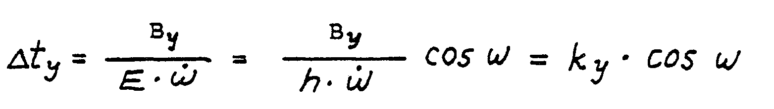
als Funktion der Abtastentfernung (E) bzw. der Flughöhe (h) und des Abtastwinkels (ω) und der Winkelgeschwindigkeit (ω• ) des Abtastelements gebildet werden.10. The method according to any one of claims 1 to 4, wherein regardless of the scanning distance (E) or the scanning angle («) object pixels of the same size (Bx = By = B) are formed) and with a regular grid over the entire area of a scan constant object pixel number (n) in the constant width (B n ) of the scanning strip, characterized in that the detector signals of the (M) individual detectors by digital control of the scanning period
as a function of the scanning distance (E) or the flight altitude (h) and the scanning angle (ω) and the angular velocity (ω • ) of the scanning element.

Applications Claiming Priority (6)
| Application Number | Priority Date | Filing Date | Title |
|---|---|---|---|
| DE3731845 | 1987-09-22 | ||
| DE3731845 | 1987-09-22 | ||
| DE3741864 | 1987-12-10 | ||
| DE3741864 | 1987-12-10 | ||
| DE19883830577 DE3830577C3 (en) | 1988-09-08 | 1988-09-08 | Digital sampling |
| DE3830577 | 1988-09-08 |
Publications (3)
| Publication Number | Publication Date |
|---|---|
| EP0308932A2 true EP0308932A2 (en) | 1989-03-29 |
| EP0308932A3 EP0308932A3 (en) | 1991-04-17 |
| EP0308932B1 EP0308932B1 (en) | 1996-06-12 |
Family
ID=27196530
Family Applications (1)
| Application Number | Title | Priority Date | Filing Date |
|---|---|---|---|
| EP88115594A Expired - Lifetime EP0308932B1 (en) | 1987-09-22 | 1988-09-22 | Method and device for scanning an object |
Country Status (3)
| Country | Link |
|---|---|
| US (1) | US5043924A (en) |
| EP (1) | EP0308932B1 (en) |
| DE (1) | DE3855360D1 (en) |
Cited By (3)
| Publication number | Priority date | Publication date | Assignee | Title |
|---|---|---|---|---|
| EP0503103A1 (en) * | 1989-02-06 | 1992-09-16 | Honeywell Ag | Electronic zoom for wide-angle line scanners |
| WO1993001977A1 (en) * | 1991-07-16 | 1993-02-04 | James Bertram King | In-flight aircraft monitoring system |
| DE102010046391A1 (en) * | 2010-09-24 | 2012-03-29 | Deutsches Zentrum für Luft- und Raumfahrt e.V. | Optical system for remote sensing camera for capturing image, has common lens attached to two time delay integration-line-sensors, where speed ratios of integration-line-sensors are adjusted to different object distances |
Families Citing this family (14)
| Publication number | Priority date | Publication date | Assignee | Title |
|---|---|---|---|---|
| US5712678A (en) * | 1988-12-08 | 1998-01-27 | Messerschmitt Bolkow Blohm Gmbh | Method and apparatus for scanning a terrain surface |
| US5420789A (en) * | 1991-07-02 | 1995-05-30 | Itt Defense & Electronics | Geometrically corrected large angle whiskbroom scanner for low earth orbiting satellites |
| US5481479A (en) * | 1992-12-10 | 1996-01-02 | Loral Fairchild Corp. | Nonlinear scanning to optimize sector scan electro-optic reconnaissance system performance |
| US5668593A (en) * | 1995-06-07 | 1997-09-16 | Recon/Optical, Inc. | Method and camera system for step frame reconnaissance with motion compensation |
| FR2743462B1 (en) * | 1996-01-04 | 1998-01-30 | Commissariat Energie Atomique | DEVICE FOR READING DETECTOR ARRAYS WITH TDI EFFECT |
| DE19822249A1 (en) * | 1998-05-18 | 1999-11-25 | Honeywell Ag | Method for scanning images from the air |
| US6943803B1 (en) * | 1998-09-21 | 2005-09-13 | Evans & Sutherland Computer Corporation | Anti-aliased, textured, geocentric and layered fog graphics display method and apparatus |
| US7095364B1 (en) * | 2005-08-04 | 2006-08-22 | The Boeing Company | Altitude measurement system and associated methods |
| US7891818B2 (en) | 2006-12-12 | 2011-02-22 | Evans & Sutherland Computer Corporation | System and method for aligning RGB light in a single modulator projector |
| US8358317B2 (en) | 2008-05-23 | 2013-01-22 | Evans & Sutherland Computer Corporation | System and method for displaying a planar image on a curved surface |
| US8702248B1 (en) | 2008-06-11 | 2014-04-22 | Evans & Sutherland Computer Corporation | Projection method for reducing interpixel gaps on a viewing surface |
| US8077378B1 (en) | 2008-11-12 | 2011-12-13 | Evans & Sutherland Computer Corporation | Calibration system and method for light modulation device |
| US9641826B1 (en) | 2011-10-06 | 2017-05-02 | Evans & Sutherland Computer Corporation | System and method for displaying distant 3-D stereo on a dome surface |
| RU2654300C1 (en) * | 2016-11-14 | 2018-05-17 | Акционерное общество "Российская корпорация ракетно-космического приборостроения и информационных систем" (АО "Российские космические системы") | Multi-zone scanning device with a matrix photodetector device |
Citations (5)
| Publication number | Priority date | Publication date | Assignee | Title |
|---|---|---|---|---|
| US2967211A (en) * | 1952-11-13 | 1961-01-03 | Servo Corp Of America | Optical scanning mechanism |
| US3619029A (en) * | 1965-11-26 | 1971-11-09 | Texas Instruments Inc | Infrared-reconnaissance system |
| DE1623426C3 (en) * | 1967-12-01 | 1973-12-20 | Eltro Gmbh, Gesellschaft Fuer Strahlungstechnik, 6900 Heidelberg | Optoelectronic process for recording thermal images |
| US3864513A (en) * | 1972-09-11 | 1975-02-04 | Grumman Aerospace Corp | Computerized polarimetric terrain mapping system |
| EP0145249A2 (en) * | 1983-11-04 | 1985-06-19 | Gec-Marconi Avionics (Holdings) Limited | Image distortion correction system for electro-optic sensors |
Family Cites Families (4)
| Publication number | Priority date | Publication date | Assignee | Title |
|---|---|---|---|---|
| US3901595A (en) * | 1974-02-13 | 1975-08-26 | Bendix Corp | Parallel line scanning system for stereomapping |
| US3973243A (en) * | 1974-10-15 | 1976-08-03 | The Bendix Corporation | Digital image processor |
| US4724526A (en) * | 1984-09-11 | 1988-02-09 | Bausch & Lomb Incorporated | Apparatus and method for determining object elevation and height from images thereof |
| US4669048A (en) * | 1984-09-14 | 1987-05-26 | Carl-Zeiss-Stiftung | Computer-controlled evaluation of aerial stereo images |
-
1988
- 1988-09-22 DE DE3855360T patent/DE3855360D1/en not_active Expired - Fee Related
- 1988-09-22 US US07/247,958 patent/US5043924A/en not_active Expired - Fee Related
- 1988-09-22 EP EP88115594A patent/EP0308932B1/en not_active Expired - Lifetime
Patent Citations (5)
| Publication number | Priority date | Publication date | Assignee | Title |
|---|---|---|---|---|
| US2967211A (en) * | 1952-11-13 | 1961-01-03 | Servo Corp Of America | Optical scanning mechanism |
| US3619029A (en) * | 1965-11-26 | 1971-11-09 | Texas Instruments Inc | Infrared-reconnaissance system |
| DE1623426C3 (en) * | 1967-12-01 | 1973-12-20 | Eltro Gmbh, Gesellschaft Fuer Strahlungstechnik, 6900 Heidelberg | Optoelectronic process for recording thermal images |
| US3864513A (en) * | 1972-09-11 | 1975-02-04 | Grumman Aerospace Corp | Computerized polarimetric terrain mapping system |
| EP0145249A2 (en) * | 1983-11-04 | 1985-06-19 | Gec-Marconi Avionics (Holdings) Limited | Image distortion correction system for electro-optic sensors |
Cited By (4)
| Publication number | Priority date | Publication date | Assignee | Title |
|---|---|---|---|---|
| EP0503103A1 (en) * | 1989-02-06 | 1992-09-16 | Honeywell Ag | Electronic zoom for wide-angle line scanners |
| WO1993001977A1 (en) * | 1991-07-16 | 1993-02-04 | James Bertram King | In-flight aircraft monitoring system |
| DE102010046391A1 (en) * | 2010-09-24 | 2012-03-29 | Deutsches Zentrum für Luft- und Raumfahrt e.V. | Optical system for remote sensing camera for capturing image, has common lens attached to two time delay integration-line-sensors, where speed ratios of integration-line-sensors are adjusted to different object distances |
| DE102010046391B4 (en) * | 2010-09-24 | 2017-05-04 | Deutsches Zentrum für Luft- und Raumfahrt e.V. | Optical system |
Also Published As
| Publication number | Publication date |
|---|---|
| US5043924A (en) | 1991-08-27 |
| EP0308932B1 (en) | 1996-06-12 |
| DE3855360D1 (en) | 1996-07-18 |
| EP0308932A3 (en) | 1991-04-17 |
Similar Documents
| Publication | Publication Date | Title |
|---|---|---|
| EP0308932B1 (en) | Method and device for scanning an object | |
| DE2621339C2 (en) | Scanning converter for converting data in the polar coordinate system into data in the Cartesian coordinate system | |
| DE2814265C3 (en) | Device for automatic adjustment of the setting of a microscope | |
| DE3219032C2 (en) | Stereophotogrammetric recording and evaluation process and evaluation device | |
| DE19804205B4 (en) | Photogrammetric measuring method and photogrammetric measuring device | |
| DE3645031C2 (en) | ||
| CH672212A5 (en) | ||
| EP0357944A1 (en) | Diagnostic dental X-ray installation for carrying out a panoramic tomography of a patient's jaw | |
| EP0237601A1 (en) | Method for the photogrammetrical measurement of an object with at least one solid-state image sensor | |
| DE2734073A1 (en) | METHOD AND EQUIPMENT FOR SCANNING A MOVABLE INFORMATION CARRIER | |
| DE3614159C2 (en) | ||
| DE2506325A1 (en) | ARRANGEMENT FOR CONTROLLING AERIAL IMAGE CAMERAS | |
| CH616508A5 (en) | ||
| DE3434794C2 (en) | ||
| EP0558116B1 (en) | Method for radiograms and device suited therefor | |
| DE2838121C3 (en) | ||
| DE3830577C3 (en) | Digital sampling | |
| DE3829300A1 (en) | Method and device for scanning an object | |
| DE3330861C2 (en) | ||
| DE3000654A1 (en) | SYSTEM FOR REPRESENTING THE MOVEMENT OF A VEHICLE RELATIVE TO A SURFACE | |
| EP0431658B1 (en) | Method and arrangement for scanning an X-ray plate using an electrometer probe | |
| DE2609648A1 (en) | DEVICE FOR DIGITAL CAPTURING AND / OR STORAGE OF ANALOGUE INFORMATION, SUCH AS DOTS, LINES OR ANY OTHER GRAPHICAL IMAGES, ON A LEVEL TEMPLATE | |
| EP0330100B2 (en) | Optical measuring device | |
| EP0444737A2 (en) | Device for scanning a radiography | |
| DE19919487C2 (en) | Recording process and photogrammetric camera therefor |
Legal Events
| Date | Code | Title | Description |
|---|---|---|---|
| PUAI | Public reference made under article 153(3) epc to a published international application that has entered the european phase |
Free format text: ORIGINAL CODE: 0009012 |
|
| AK | Designated contracting states |
Kind code of ref document: A2 Designated state(s): CH DE FR GB IT LI |
|
| 17P | Request for examination filed |
Effective date: 19901212 |
|
| PUAL | Search report despatched |
Free format text: ORIGINAL CODE: 0009013 |
|
| AK | Designated contracting states |
Kind code of ref document: A3 Designated state(s): CH DE FR GB IT LI |
|
| 17Q | First examination report despatched |
Effective date: 19920818 |
|
| RAP1 | Party data changed (applicant data changed or rights of an application transferred) |
Owner name: DEUTSCHE AEROSPACE AKTIENGESELLSCHAFT |
|
| RAP1 | Party data changed (applicant data changed or rights of an application transferred) |
Owner name: DAIMLER-BENZ AEROSPACE AKTIENGESELLSCHAFT |
|
| GRAH | Despatch of communication of intention to grant a patent |
Free format text: ORIGINAL CODE: EPIDOS IGRA |
|
| GRAH | Despatch of communication of intention to grant a patent |
Free format text: ORIGINAL CODE: EPIDOS IGRA |
|
| GRAA | (expected) grant |
Free format text: ORIGINAL CODE: 0009210 |
|
| AK | Designated contracting states |
Kind code of ref document: B1 Designated state(s): CH DE FR GB IT LI |
|
| REG | Reference to a national code |
Ref country code: CH Ref legal event code: NV Representative=s name: BOVARD AG PATENTANWAELTE |
|
| ET | Fr: translation filed | ||
| REF | Corresponds to: |
Ref document number: 3855360 Country of ref document: DE Date of ref document: 19960718 |
|
| ITF | It: translation for a ep patent filed |
Owner name: STUDIO JAUMANN |
|
| GBT | Gb: translation of ep patent filed (gb section 77(6)(a)/1977) |
Effective date: 19960918 |
|
| PLBE | No opposition filed within time limit |
Free format text: ORIGINAL CODE: 0009261 |
|
| STAA | Information on the status of an ep patent application or granted ep patent |
Free format text: STATUS: NO OPPOSITION FILED WITHIN TIME LIMIT |
|
| 26N | No opposition filed | ||
| REG | Reference to a national code |
Ref country code: GB Ref legal event code: 732E |
|
| REG | Reference to a national code |
Ref country code: CH Ref legal event code: PUE Owner name: DAIMLER-BENZ AEROSPACE AKTIENGESELLSCHAFT -DANN AN |
|
| REG | Reference to a national code |
Ref country code: FR Ref legal event code: TP |
|
| PGFP | Annual fee paid to national office [announced via postgrant information from national office to epo] |
Ref country code: GB Payment date: 20010814 Year of fee payment: 14 |
|
| PGFP | Annual fee paid to national office [announced via postgrant information from national office to epo] |
Ref country code: CH Payment date: 20010816 Year of fee payment: 14 |
|
| PGFP | Annual fee paid to national office [announced via postgrant information from national office to epo] |
Ref country code: DE Payment date: 20010903 Year of fee payment: 14 |
|
| PGFP | Annual fee paid to national office [announced via postgrant information from national office to epo] |
Ref country code: FR Payment date: 20010904 Year of fee payment: 14 |
|
| REG | Reference to a national code |
Ref country code: GB Ref legal event code: IF02 |
|
| PG25 | Lapsed in a contracting state [announced via postgrant information from national office to epo] |
Ref country code: GB Free format text: LAPSE BECAUSE OF NON-PAYMENT OF DUE FEES Effective date: 20020922 |
|
| PG25 | Lapsed in a contracting state [announced via postgrant information from national office to epo] |
Ref country code: LI Free format text: LAPSE BECAUSE OF NON-PAYMENT OF DUE FEES Effective date: 20020930 Ref country code: CH Free format text: LAPSE BECAUSE OF NON-PAYMENT OF DUE FEES Effective date: 20020930 |
|
| PG25 | Lapsed in a contracting state [announced via postgrant information from national office to epo] |
Ref country code: DE Free format text: LAPSE BECAUSE OF NON-PAYMENT OF DUE FEES Effective date: 20030401 |
|
| GBPC | Gb: european patent ceased through non-payment of renewal fee |
Effective date: 20020922 |
|
| REG | Reference to a national code |
Ref country code: CH Ref legal event code: PL |
|
| PG25 | Lapsed in a contracting state [announced via postgrant information from national office to epo] |
Ref country code: FR Free format text: LAPSE BECAUSE OF NON-PAYMENT OF DUE FEES Effective date: 20030603 |
|
| REG | Reference to a national code |
Ref country code: FR Ref legal event code: ST |
|
| PG25 | Lapsed in a contracting state [announced via postgrant information from national office to epo] |
Ref country code: IT Free format text: LAPSE BECAUSE OF NON-PAYMENT OF DUE FEES;WARNING: LAPSES OF ITALIAN PATENTS WITH EFFECTIVE DATE BEFORE 2007 MAY HAVE OCCURRED AT ANY TIME BEFORE 2007. THE CORRECT EFFECTIVE DATE MAY BE DIFFERENT FROM THE ONE RECORDED. Effective date: 20050922 |