EP0311011A2 - Device for separating the components of a liquid sample having higher and lower specific gravities - Google Patents
Device for separating the components of a liquid sample having higher and lower specific gravities Download PDFInfo
- Publication number
- EP0311011A2 EP0311011A2 EP88116394A EP88116394A EP0311011A2 EP 0311011 A2 EP0311011 A2 EP 0311011A2 EP 88116394 A EP88116394 A EP 88116394A EP 88116394 A EP88116394 A EP 88116394A EP 0311011 A2 EP0311011 A2 EP 0311011A2
- Authority
- EP
- European Patent Office
- Prior art keywords
- cup
- dual
- assembly
- specific gravity
- shaped
- Prior art date
- Legal status (The legal status is an assumption and is not a legal conclusion. Google has not performed a legal analysis and makes no representation as to the accuracy of the status listed.)
- Granted
Links
Images


Classifications
-
- A—HUMAN NECESSITIES
- A61—MEDICAL OR VETERINARY SCIENCE; HYGIENE
- A61B—DIAGNOSIS; SURGERY; IDENTIFICATION
- A61B5/00—Measuring for diagnostic purposes; Identification of persons
- A61B5/14—Devices for taking samples of blood ; Measuring characteristics of blood in vivo, e.g. gas concentration within the blood, pH-value of blood
-
- B—PERFORMING OPERATIONS; TRANSPORTING
- B01—PHYSICAL OR CHEMICAL PROCESSES OR APPARATUS IN GENERAL
- B01L—CHEMICAL OR PHYSICAL LABORATORY APPARATUS FOR GENERAL USE
- B01L3/00—Containers or dishes for laboratory use, e.g. laboratory glassware; Droppers
- B01L3/50—Containers for the purpose of retaining a material to be analysed, e.g. test tubes
- B01L3/502—Containers for the purpose of retaining a material to be analysed, e.g. test tubes with fluid transport, e.g. in multi-compartment structures
- B01L3/5021—Test tubes specially adapted for centrifugation purposes
- B01L3/50215—Test tubes specially adapted for centrifugation purposes using a float to separate phases
-
- G—PHYSICS
- G01—MEASURING; TESTING
- G01N—INVESTIGATING OR ANALYSING MATERIALS BY DETERMINING THEIR CHEMICAL OR PHYSICAL PROPERTIES
- G01N33/00—Investigating or analysing materials by specific methods not covered by groups G01N1/00 - G01N31/00
- G01N33/48—Biological material, e.g. blood, urine; Haemocytometers
- G01N33/483—Physical analysis of biological material
- G01N33/487—Physical analysis of biological material of liquid biological material
- G01N33/49—Blood
- G01N33/491—Blood by separating the blood components
-
- B—PERFORMING OPERATIONS; TRANSPORTING
- B01—PHYSICAL OR CHEMICAL PROCESSES OR APPARATUS IN GENERAL
- B01L—CHEMICAL OR PHYSICAL LABORATORY APPARATUS FOR GENERAL USE
- B01L2400/00—Moving or stopping fluids
- B01L2400/06—Valves, specific forms thereof
- B01L2400/0633—Valves, specific forms thereof with moving parts
Definitions
- This invention relates generally to a device which separates what is usually called the heavier and lighter fractions of a liquid sample. More particularly, this invention relates to devices or assemblies utilizing an evacuated tube placed under centrifugation wherein a liquid sample is placed in the tube, and subsequently the tube is subjected to centrifugal force in order to cause the heavier fraction (or the fraction having the higher specific gravity) to the closed end of the tube while the lighter fraction (or that fraction having a lower specific gravity) moves toward the open end of the tube.
- Such arrangements utilize some sort of barrier for moving into the area adjacent the two phases of the sample being separated in order to maintain the components separated for subsequent examination of the individual components.
- the thrust of all of the devices developed for use in the environment discussed above is to provide a barrier which divides cleanly the heavier and lighter fractions of the sample being separated.
- the material utilized generally at this time for providing the barrier or separation between the heavier and lighter phases or the components having the lower and higher specific gravities include various thixotropic gel materials or sealants such as those described in U.S. Patent No. 3,852,194, which is a mixture of silicone and hydrophobic silicon dioxide powders.
- Another form of thixotropic gel is a polyester gel which is presently utilized for a great many serum and/or plasma separation tube devices on the market. That material is taught and claimed in U.S. Patent No. 4,101,422 issued July 18, 1978.
- the present polyester gel serum separation tube requires, for example, special manufacturing equipment to prepare the gel and to fill the tubes. Both processes require rigid controls.
- the shelf-life of the product is limited in that globules are sometimes released from the gel mass or network. These globules have a specific gravity that is less than the separated serum and will float in the serum and can clog the measuring instruments, subsequently, during the clinical examination of the sample collected in the tube.
- the gel is chemically inert to blood samples, if certain drugs are present in the blood sample when it is taken, there can be an adverse chemical reaction with the gel interface.
- a mechanical separator which is non-temperature dependent during storage and shipping, is more stable to radiation sterilization, and eliminates the need for a special transport tube which is required for gel separation devices as discussed above for improved barrier integrity during transportation.
- the arrangement herein utilizes a dual component mechanical assembly arranged to move in an evacuated tube under the action of centrifugal force in order to separate the two portions of the sample.
- the assembly includes a substantially rigid core component which nests within a cup-shaped elastomer component.
- the solid component under certain operating conditions, is movable within the cup-shaped component.
- the two components operate together, and complement each other under the differing pressure differentials which are inherent in serum separation tubes, to provide alternating dual seals and open flow paths in response to those pressure differentials. As such, the arrangement herein provides a much more precise division between the two portions being separated from the original sample introduced into the tube.
- the dual component device of the invention herein has a conventional specific gravity range within between about 1.03 and 1.09, and more specifically within the range of between about 1.05 and 1.06 so that the device will come to rest under centrifugal force substantially at the border between the heavier and lighter phases of the sample under consideration.
- the central core portion of the dual component device may be comprised of a substantially rigid moldable thermoplastic material such as polyvinyl chloride, polystyrene, polyethylene, polypropylene, polyesters, and mixtures thereof, with a limitation being that the material is inert to the sample introduced in the assembly of the invention so as not to interfere with any desired subsequent testing.
- the cup-shaped portion may be comprised of any natural or synthetic elastomer or mixtures thereof, with, again, the limitation concerning being inert to the sample of interest.
- the stopper may be comprised of similar elastomer combinations.
- Fig. 1 illustrates the invention in the form of a serum separation tube having a closed end and an open end with the latter being arranged to be sealed by a cooperating stopper so as to maintain a vacuum in the tube once the stopper is in place.
- the assembly of the invention generally designated 10 includes tube 12 having an open end 14 and a closed end 16.
- Tube 12 is transparent so that the user may readily observe what is going on with the contents thereof.
- Tube 12 may be plastic but it is preferably glass.
- Elastomeric stopper 20 is provided for insertion into the open end 14 of tube 12.
- Stopper 20 includes an upper annular portion 22 and a lower annular portion 26 of lesser diameter, with the lower portion 26 being arranged to be inserted into tube 12 so that the internal surface 32 of tube 12 adheres to and seals against the external surface 30 of annular portion 26.
- an annular ledge or abutment 24 is arranged to seat on the top surface of open end 14 of tube 12 to further enhance the sealing between tube 12 and stopper 20.
- Stopper 20 further includes a vent 28 positioned at one point in the circumferential extent of the lower portion 26 of stopper 20. The purpose of vent 28 will be described below.
- Tube 12 may be open at both ends (not shown) with a stopper 20 inserted in each end.
- a dual separator assembly 34 including a molded solid core 36 and an elastomeric cup-shaped flexible component 38.
- Solid core 36 nests in the cup-shaped elastomeric component 38.
- These two parts form dual seals 60 and 70. This is achieved by the annular ring portion 46 of solid core 36 cooperating with the upper annular ring portion 44 of the elastomeric cup-shaped lower portion 38.
- central core component 36 includes a snap connector 50, integral with central core component 36, which extends through a bore 52 in the bottom wall 64 of the elastomeric cup-shaped component 38.
- Groove 54 serves to provide liquid access adjacent the bottom of component 36.
- the snap connector 50 extends through the bore and spreads to hold the two parts together.
- bottom wall 64 of component 38 is a plurality of apertures 48 providing flow communication between area 78 below the dual separator assembly 34, and area 84 between the two components forming the dual assembly 34 in conjunction with groove 54.
- Fig. 2 the positioning of the parts is shown for the assembly 10 when evacuation is initiated.
- the application of a vacuum causes a withdrawal of air from the internal space of tube 12 simultaneously with the stopper gradually sliding into the tube into a sealing closure of the open end 14 of tube 12.
- a pressure differential has developed between the pressure 56 above the assembly 34 ( ⁇ P) and the pressure 58 below the assembly 34.
- the assembly 34 is unseated due to that pressure differential.
- cylindrical core 36 is forced upward, and its outermost diameter is disengaged from the innermost diameter the cup-shaped portion 38.
- This causes a reduction in pressure, in addition, in a radial direction on the annular portion 44 of cup-shaped portion 38, along with the flexing upward of the bottom wall 64 which is in the form of a stretchable diaphragm.
- the outermost surface 40 of the upper annular sealing portion 44 of portion 38 moves radially inwardly from the inner surface 32 of tube 12. This causes a passage 62 and communication between the area above the assembly 34 and the area below assembly 34 as well as flow through passage 70 between surfaces 42 and 46.
- stopper 20 When the evacuation has been completed, as shown in Fig. 3, stopper 20 is completely inserted into the open end 14 of tube 12.
- pressures 56 and 58 have again equalized (P1), diaphragm wall 64 of the cup-shaped lower portion 38 of the assembly 34 moves downwardly into its normal position, and solid core 36 is pulled in a downward direction to return to the position causing the reestablishment of inner and outer dual seals 60 and 70.
- a blood draw needle 72 has been inserted through a stopper 20 for introducing a blood sample into container 12 from the vein of a patient.
- the assembly 34 is in the normal position shown in Fig. 4 with equalized vacuum 56, 58 above and below the assembly 34, respectively.
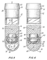
- a pressure differential is set up again between the pressure 56 ( > P1) and the pressure 58 (P1), with the pressure 56 being greater than the evacuated pressure established prior to blood draw. Because of the pressure differential, again, the separator assembly 34 moves into an unsealed position as shown in Fig. 5 with the solid core moving downwardly into the cup-shaped portion 38. Also, because of the pressure differential, the diaphragm bottom wall 64 of portion 38 moves downwardly.
- the tube 12 is subjected to centrifugation.
- the assembly 34 is forced into the unsealed position shown in Fig. 7. In this position, there is open passage between the area 78 below assembly 34 and the area 90 above assembly 34.
- the assembly 34 has a specific gravity which is heavier than the serum and/or plasma or light phase of the sample being centrifuged in container 12, that portion of the sample having a specific gravity heavier than the assembly 34 moves below the assembly, while that portion of the sample which is lighter than the specific gravity of assembly 34 moves above the assembly. (Fig. 8)
- the assembly 34 itself moves to the interface between the heavier phase 94 and the lighter phase 90 of the initial sample taken.
- diaphragm 64 moves to the position shown in Fig. 8, and the dual seals 60, 70 move into place simultaneously with this movement of the assembly into its position at the interface, as discussed above. Because of this, a barrier is formed between the two phases.
- Fig. 9 shows a cross-sectional view of the cup-shaped component 100 of this embodiment.
- component 100 is configured somewhat differently than 38 in that side walls 104 are clearly thinner than bottom wall 106.
- bottom wall 106 has a beveled configuration ending in a central plateau 110 which imparts more rigidity to wall 106.
- a plurality of liquid flow communication bores 108 are disposed around the circumference of wall 106, as clearly shown in Fig. 10.
- Fig. 10 in this regard is a top-plan view of component 100.
- Fig. 11 shows the solid central core component 114 with sealing ring 118 and sealing surface 122 cooperating in the sealing position with the resilient cup-shaped component 100.
- an integral snap connector 116 depends from the bottom surface of core 114 with an enlarged portion 118 which snaps through bore 112 into locking engagement with the bottom surface of wall 106.
- the device is in the sealed position or mode as it is assembled and inserted into tube 12 and engaging surface 32 thereof.
- Side wall 104 as can be seen, has less curvature due to the compression of the outer seal 124 with surface 32. While the device is fairly tight at this period it can be moved or positioned in the tube. Bottom point 103 may touch surface 32 depending upon tolerances.
- Fig. 12 shows the device in the unsealed upper position or mode which takes place during evacuation of tube 12. Due to the pressure differential above and below the dual component system, a force is applied upward on the system. The seal 124 resists most of the force imparted and the device remains generally stationary. The strength of the bottom wall 106 also resists this force. As can be seen, however, the thinner and weaker side wall 104 collapses until pressure equilibrium is reached, at which time the side wall will return to its natural state and pull core 114 back to its sealed position shown in Fig. 11 with dual seals 124 and 126.
- the device 100, 114 is shown in the unsealed downward position or mode. This occurs during blood draw or centrifugation. During blood draw, the pressure differential creates a downward force. Thus, the beveled bottom wall 106 moves or collapses downward pulling core 114 into the unsealed position through snap connection 116, and then returns to normal when pressure equalizes. During centrifugation, the device moves up or down the tube in the unsealed position as described previously with the embodiment 34.
- the invention provides a dual assembly arrangement for separating a liquid sample into the components thereof having a higher specific gravity and the components thereof having a lower specific gravity, or more specifically the serum/plasma phase and the cellular phase of a blood sample.
- the arrangement herein utilizes a unique dual arrangement of a solid core with a flexible cup-shaped diaphragm portion holding the solid core, and with the two parts interacting with each other in response to variations in pressure differential on each side thereof to form dual seals at appropriate times during use, and to provide flow passage around this dual assembly, at appropriate times to cause the appropriate separation of the two phases.
- the arrangement herein is a mechanical arrangement as opposed to a gel, less rigid control is required in order to prepare and manufacture the device of the invention. Moreover, less procedures are required in order to produce a product, in accordance herewith, having an extended shelf-life, with the product being chemically inert to any chemicals in a sample introduced into the device.
- the device of the invention is substantially more stable in the environment of radiation sterilization, and is not temperature dependent during storage.
Abstract
Description
- This invention relates generally to a device which separates what is usually called the heavier and lighter fractions of a liquid sample. More particularly, this invention relates to devices or assemblies utilizing an evacuated tube placed under centrifugation wherein a liquid sample is placed in the tube, and subsequently the tube is subjected to centrifugal force in order to cause the heavier fraction (or the fraction having the higher specific gravity) to the closed end of the tube while the lighter fraction (or that fraction having a lower specific gravity) moves toward the open end of the tube.
- Such arrangements utilize some sort of barrier for moving into the area adjacent the two phases of the sample being separated in order to maintain the components separated for subsequent examination of the individual components. The thrust of all of the devices developed for use in the environment discussed above is to provide a barrier which divides cleanly the heavier and lighter fractions of the sample being separated.
- When taking blood samples for test purposes, for example, whole blood generally is drawn into an evacuated collection tube, and the tube is centrifuged to separate the blood into the relatively lighter phase or component, as discussed above which is serum or plasma, and a heavier cellular phase. A variety of mechanical devices have been utilized in the past including piston-type arrangements for moving freely in the liquid sample in the evacuated tube so that the piston arrangements subsequently come to rest in the divided area between the heavier and lighter phases. While these mechanical arrangements have proved useful in a limited sense, they have not been entirely successful because they do not provide the clean separation discussed above.
- The material utilized generally at this time for providing the barrier or separation between the heavier and lighter phases or the components having the lower and higher specific gravities include various thixotropic gel materials or sealants such as those described in U.S. Patent No. 3,852,194, which is a mixture of silicone and hydrophobic silicon dioxide powders. Another form of thixotropic gel is a polyester gel which is presently utilized for a great many serum and/or plasma separation tube devices on the market. That material is taught and claimed in U.S. Patent No. 4,101,422 issued July 18, 1978.
- However, the present polyester gel serum separation tube requires, for example, special manufacturing equipment to prepare the gel and to fill the tubes. Both processes require rigid controls. Moreover, the shelf-life of the product is limited in that globules are sometimes released from the gel mass or network. These globules have a specific gravity that is less than the separated serum and will float in the serum and can clog the measuring instruments, subsequently, during the clinical examination of the sample collected in the tube.
- Moreover, while the gel is chemically inert to blood samples, if certain drugs are present in the blood sample when it is taken, there can be an adverse chemical reaction with the gel interface.
- With this invention, by contrast, a mechanical separator is utilized which is non-temperature dependent during storage and shipping, is more stable to radiation sterilization, and eliminates the need for a special transport tube which is required for gel separation devices as discussed above for improved barrier integrity during transportation. The arrangement herein utilizes a dual component mechanical assembly arranged to move in an evacuated tube under the action of centrifugal force in order to separate the two portions of the sample.
- The assembly includes a substantially rigid core component which nests within a cup-shaped elastomer component. The solid component, under certain operating conditions, is movable within the cup-shaped component. The two components operate together, and complement each other under the differing pressure differentials which are inherent in serum separation tubes, to provide alternating dual seals and open flow paths in response to those pressure differentials. As such, the arrangement herein provides a much more precise division between the two portions being separated from the original sample introduced into the tube.
- Before describing this invention in more detail, it should be well to note that the dual component device of the invention herein has a conventional specific gravity range within between about 1.03 and 1.09, and more specifically within the range of between about 1.05 and 1.06 so that the device will come to rest under centrifugal force substantially at the border between the heavier and lighter phases of the sample under consideration.
- In addition, the central core portion of the dual component device may be comprised of a substantially rigid moldable thermoplastic material such as polyvinyl chloride, polystyrene, polyethylene, polypropylene, polyesters, and mixtures thereof, with a limitation being that the material is inert to the sample introduced in the assembly of the invention so as not to interfere with any desired subsequent testing. The cup-shaped portion, in turn, may be comprised of any natural or synthetic elastomer or mixtures thereof, with, again, the limitation concerning being inert to the sample of interest. The stopper may be comprised of similar elastomer combinations.
- While the invention is directed to evacuated tubes in order to facilitate introduction of blood samples from the vein of a patient, it will be understood that the container in accordance with this invention does not necessarily need to be evacuated.
- Other objects and advantages of this invention will be apparent from the following description, the accompanying drawings, and the appended claims.
-
- Figs. 1-8 are longitudinal sectional views illustrating the device of the invention, and showing the various components thereof in different positions of movement sequentially during the use of the device of the invention;
- Figs. 9-13 show a further embodiment illustrating the device of the invention, again showing the various components thereof and the positioning sequentially of those components in use.
- Referring to the drawings in which like reference characters refer to like parts throughout the several views thereof, Fig. 1 illustrates the invention in the form of a serum separation tube having a closed end and an open end with the latter being arranged to be sealed by a cooperating stopper so as to maintain a vacuum in the tube once the stopper is in place.
- In Fig. 1, the assembly of the invention generally designated 10 includes
tube 12 having anopen end 14 and a closedend 16. Tube 12 is transparent so that the user may readily observe what is going on with the contents thereof.Tube 12 may be plastic but it is preferably glass. -
Elastomeric stopper 20 is provided for insertion into theopen end 14 oftube 12.Stopper 20 includes an upperannular portion 22 and a lowerannular portion 26 of lesser diameter, with thelower portion 26 being arranged to be inserted intotube 12 so that theinternal surface 32 oftube 12 adheres to and seals against theexternal surface 30 ofannular portion 26. Because of the differing diameters oflower portion 26 andupper portion 22 ofstopper 20, an annular ledge orabutment 24 is arranged to seat on the top surface ofopen end 14 oftube 12 to further enhance the sealing betweentube 12 and stopper 20.Stopper 20 further includes avent 28 positioned at one point in the circumferential extent of thelower portion 26 ofstopper 20. The purpose ofvent 28 will be described below.Tube 12 may be open at both ends (not shown) with astopper 20 inserted in each end. - Further shown in Fig. 1 is a
dual separator assembly 34, including a moldedsolid core 36 and an elastomeric cup-shapedflexible component 38.Solid core 36 nests in the cup-shapedelastomeric component 38. These two parts formdual seals annular ring portion 46 ofsolid core 36 cooperating with the upperannular ring portion 44 of the elastomeric cup-shapedlower portion 38. - Thus,
surface 40 ofportion 44 of the cup-shapedelastomeric portion 38 bears against theinternal surface 32 oftube 12 under certain conditions of operation of the device herein, whileinternal surface 42 ofportion 44 bears against theannular ring 46, as discussed above. These dual sealing positions come about when thepressure 56 above thedual component arrangement 34 is the same as thepressure 58 below thedual component 34. - Further as can be seen in Fig. 1,
central core component 36 includes asnap connector 50, integral withcentral core component 36, which extends through abore 52 in thebottom wall 64 of the elastomeric cup-shaped component 38. Groove 54 serves to provide liquid access adjacent the bottom ofcomponent 36. As can be seen in Fig. 1, thesnap connector 50 extends through the bore and spreads to hold the two parts together. Further inbottom wall 64 ofcomponent 38 is a plurality ofapertures 48 providing flow communication betweenarea 78 below thedual separator assembly 34, andarea 84 between the two components forming thedual assembly 34 in conjunction withgroove 54. - In Fig. 1, because
stopper 20 has not been seated within and sealed against theinternal surface 32 oftube 12, the pressure differential betweenpressures dual assembly 34 are equal and at atmospheric pressure so that thedual assembly 34 provides the dual sealing action atannular contact points - Referring now to Fig. 2, the positioning of the parts is shown for the
assembly 10 when evacuation is initiated. In this connection, it should be borne in mind that it is within the purview of the practitioner-in-the-art to simultaneously seat theelastomeric stopper 20 in thetube 12 with the evacuation of the tube throughvent 28. That is, the application of a vacuum causes a withdrawal of air from the internal space oftube 12 simultaneously with the stopper gradually sliding into the tube into a sealing closure of theopen end 14 oftube 12. Thus, in the position shown in Fig. 2, a pressure differential has developed between thepressure 56 above the assembly 34 ( < P) and thepressure 58 below theassembly 34. As a result, theassembly 34 is unseated due to that pressure differential. - Referring to Figs. 1 and 2,
cylindrical core 36 is forced upward, and its outermost diameter is disengaged from the innermost diameter the cup-shaped portion 38. This causes a reduction in pressure, in addition, in a radial direction on theannular portion 44 of cup-shaped portion 38, along with the flexing upward of thebottom wall 64 which is in the form of a stretchable diaphragm. Theoutermost surface 40 of the upperannular sealing portion 44 ofportion 38 moves radially inwardly from theinner surface 32 oftube 12. This causes apassage 62 and communication between the area above theassembly 34 and the area belowassembly 34 as well as flow throughpassage 70 betweensurfaces - When the evacuation has been completed, as shown in Fig. 3,
stopper 20 is completely inserted into theopen end 14 oftube 12. In addition, becausepressures diaphragm wall 64 of the cup-shapedlower portion 38 of theassembly 34 moves downwardly into its normal position, andsolid core 36 is pulled in a downward direction to return to the position causing the reestablishment of inner and outerdual seals - Referring now to Fig. 4, a
blood draw needle 72 has been inserted through astopper 20 for introducing a blood sample intocontainer 12 from the vein of a patient. At the initial start of a blood draw, theassembly 34 is in the normal position shown in Fig. 4 with equalizedvacuum assembly 34, respectively. - Referring now to Fig. 5, in this position, the blood draw continues and a pressure differential is set up again between the pressure 56 ( > P₁) and the pressure 58 (P₁), with the
pressure 56 being greater than the evacuated pressure established prior to blood draw. Because of the pressure differential, again, theseparator assembly 34 moves into an unsealed position as shown in Fig. 5 with the solid core moving downwardly into the cup-shapedportion 38. Also, because of the pressure differential, thediaphragm bottom wall 64 ofportion 38 moves downwardly. - As blood draw continues, blood passes through the various areas indicated at 76 in Fig. 5 and into the
bottom portion 78 belowassembly 34. For this passage, of course, bothdual seals container 12, theneedle 72 is withdrawn and equalized pressure 80 (P₂) and 82 (P₂) is established above and below assembly 34 (Fig. 6). At this point, 64 has moved upwardly to its normal position resealingdual passages - Then, the
tube 12 is subjected to centrifugation. During centrifugation, theassembly 34 is forced into the unsealed position shown in Fig. 7. In this position, there is open passage between thearea 78 belowassembly 34 and thearea 90 aboveassembly 34. Moreover, because theassembly 34 has a specific gravity which is heavier than the serum and/or plasma or light phase of the sample being centrifuged incontainer 12, that portion of the sample having a specific gravity heavier than theassembly 34 moves below the assembly, while that portion of the sample which is lighter than the specific gravity ofassembly 34 moves above the assembly. (Fig. 8) During centrifugation, theassembly 34 itself moves to the interface between theheavier phase 94 and thelighter phase 90 of the initial sample taken. At this point, when centrifugation ends,diaphragm 64 moves to the position shown in Fig. 8, and thedual seals - Referring now to Figs. 9-13, inclusive, Fig. 9 shows a cross-sectional view of the cup-shaped
component 100 of this embodiment. As can be seen,component 100 is configured somewhat differently than 38 in thatside walls 104 are clearly thinner thanbottom wall 106. Also,bottom wall 106 has a beveled configuration ending in acentral plateau 110 which imparts more rigidity towall 106. A plurality of liquid flow communication bores 108 are disposed around the circumference ofwall 106, as clearly shown in Fig. 10. Fig. 10, in this regard is a top-plan view ofcomponent 100. Also, shown in Figs. 9 and 10 is the upperannular sealing portion 102 of cup-shapedcomponent 100 with inner 120 and outer 128 sealing surfaces. - Fig. 11 shows the solid
central core component 114 with sealingring 118 and sealingsurface 122 cooperating in the sealing position with the resilient cup-shapedcomponent 100. As can be seen in Fig. 11, anintegral snap connector 116 depends from the bottom surface ofcore 114 with anenlarged portion 118 which snaps throughbore 112 into locking engagement with the bottom surface ofwall 106. - Thus, as can be seen in Fig. 11, the device is in the sealed position or mode as it is assembled and inserted into
tube 12 and engagingsurface 32 thereof.Side wall 104, as can be seen, has less curvature due to the compression of theouter seal 124 withsurface 32. While the device is fairly tight at this period it can be moved or positioned in the tube.Bottom point 103 may touchsurface 32 depending upon tolerances. - Fig. 12 shows the device in the unsealed upper position or mode which takes place during evacuation of
tube 12. Due to the pressure differential above and below the dual component system, a force is applied upward on the system. Theseal 124 resists most of the force imparted and the device remains generally stationary. The strength of thebottom wall 106 also resists this force. As can be seen, however, the thinner andweaker side wall 104 collapses until pressure equilibrium is reached, at which time the side wall will return to its natural state and pullcore 114 back to its sealed position shown in Fig. 11 withdual seals - In Fig. 13, the
device bottom wall 106 moves or collapses downward pullingcore 114 into the unsealed position throughsnap connection 116, and then returns to normal when pressure equalizes. During centrifugation, the device moves up or down the tube in the unsealed position as described previously with theembodiment 34. - Thus, as can be seen from the above, the invention provides a dual assembly arrangement for separating a liquid sample into the components thereof having a higher specific gravity and the components thereof having a lower specific gravity, or more specifically the serum/plasma phase and the cellular phase of a blood sample. The arrangement herein utilizes a unique dual arrangement of a solid core with a flexible cup-shaped diaphragm portion holding the solid core, and with the two parts interacting with each other in response to variations in pressure differential on each side thereof to form dual seals at appropriate times during use, and to provide flow passage around this dual assembly, at appropriate times to cause the appropriate separation of the two phases.
- Also, because the arrangement herein is a mechanical arrangement as opposed to a gel, less rigid control is required in order to prepare and manufacture the device of the invention. Moreover, less procedures are required in order to produce a product, in accordance herewith, having an extended shelf-life, with the product being chemically inert to any chemicals in a sample introduced into the device. In addition, the device of the invention is substantially more stable in the environment of radiation sterilization, and is not temperature dependent during storage.
- While the form of apparatus herein described constitutes a preferred embodiment of the invention, it is to be understood that the invention is not limited to this precise form of apparatus, and that changes may be made therein without departing from the scope of the invention which is defined in the appended claims.
Claims (10)
(1) a cup-shaped flexible portion;
(2) said cup-shaped flexible portion having a first annular ring adjacent the upper edge thereof;
(3) the outer circumferential edge of said first annular ring selectively movable into and out of sealing engagement with the internal wall of said container chamber in response to alternating equal and different pressures above and below said dual assembly;
(4) at least one opening in the bottom wall of said cup-shaped flexible portion providing flow communication therethrough;
(5) a round solid core portion nested in said cup-shaped portion;
(6) a second annular ring extending from the outer surface of said solid core portion;
(7) said solid core portion movable vertically in said cup-shaped portion for causing said first and second ring to move into and out of sealing engagement with each other in response to alternating equal and different pressures above and below said dual assembly; and
(8) means connecting said solid core portion and the said bottom wall of said flexible cup-shaped portion.
Priority Applications (1)
| Application Number | Priority Date | Filing Date | Title |
|---|---|---|---|
| AT88116394T ATE91022T1 (en) | 1987-10-08 | 1988-10-04 | PROCEDURE FOR SEPARATING COMPONENTS OF A LIQUID SAMPLE WITH DIFFERENT SPECIFIC WEIGHTS. |
Applications Claiming Priority (2)
| Application Number | Priority Date | Filing Date | Title |
|---|---|---|---|
| US106092 | 1987-10-08 | ||
| US07/106,092 US4818386A (en) | 1987-10-08 | 1987-10-08 | Device for separating the components of a liquid sample having higher and lower specific gravities |
Publications (3)
| Publication Number | Publication Date |
|---|---|
| EP0311011A2 true EP0311011A2 (en) | 1989-04-12 |
| EP0311011A3 EP0311011A3 (en) | 1990-05-23 |
| EP0311011B1 EP0311011B1 (en) | 1993-06-23 |
Family
ID=22309441
Family Applications (1)
| Application Number | Title | Priority Date | Filing Date |
|---|---|---|---|
| EP88116394A Expired - Lifetime EP0311011B1 (en) | 1987-10-08 | 1988-10-04 | Device for separating the components of a liquid sample having higher and lower specific gravities |
Country Status (13)
| Country | Link |
|---|---|
| US (1) | US4818386A (en) |
| EP (1) | EP0311011B1 (en) |
| JP (1) | JPH0670627B2 (en) |
| KR (1) | KR900006418B1 (en) |
| AT (1) | ATE91022T1 (en) |
| AU (1) | AU604207B2 (en) |
| BR (1) | BR8805155A (en) |
| CA (1) | CA1319659C (en) |
| DE (1) | DE3882000T2 (en) |
| DK (1) | DK171289B1 (en) |
| MX (1) | MX165560B (en) |
| NZ (1) | NZ226423A (en) |
| ZA (1) | ZA887496B (en) |
Cited By (9)
| Publication number | Priority date | Publication date | Assignee | Title |
|---|---|---|---|---|
| WO1998051411A2 (en) * | 1997-05-12 | 1998-11-19 | C.A. Greiner & Söhne Gesellschaft Mbh | Separating in a centrifugable container and separating method |
| EP1006360A2 (en) * | 1998-12-05 | 2000-06-07 | Becton Dickinson and Company | Device and method for separating components of a fluid sample |
| US7188734B2 (en) | 2001-03-30 | 2007-03-13 | Greiner Bio-One Gmbh | Holding device, particularly for bodily fluids, comprising a separating device, and a separating device therefor |
| EP2277625A1 (en) | 2004-01-23 | 2011-01-26 | Greiner Bio-One GmbH | Retaining device for blood, body fluids, tissue samples or tissue cultures |
| EP2376232A1 (en) * | 2008-12-04 | 2011-10-19 | Thermogenesis Corp. | Apparatus and method for separating and isolating components of a biological fluid |
| US8177072B2 (en) | 2008-12-04 | 2012-05-15 | Thermogenesis Corp. | Apparatus and method for separating and isolating components of a biological fluid |
| US8309343B2 (en) | 2008-12-01 | 2012-11-13 | Baxter International Inc. | Apparatus and method for processing biological material |
| AU2012203335B2 (en) * | 2008-03-05 | 2014-04-24 | Becton, Dickinson And Company | Capillary action collection device and container assembly |
| RU2743143C1 (en) * | 2019-08-13 | 2021-02-15 | Зарстедт Аг Унд Ко. Кг | Separating body and method for separating blood plasma and blood cells |
Families Citing this family (65)
| Publication number | Priority date | Publication date | Assignee | Title |
|---|---|---|---|---|
| DK119490D0 (en) * | 1990-05-14 | 1990-05-14 | Unes As | Apparatus for the preparation of a concentrate of coagulation factors, such as the fibrinogen, from a blood portion |
| DK167517B1 (en) * | 1991-11-11 | 1993-11-15 | Squibb & Sons Inc | CONTAINER FOR INCLUSION AND SEPARATION OF A FLUID, PRETTY BLOOD PLASMA, IN ITS INGREDIENTS |
| IL100828A (en) * | 1992-01-31 | 2002-05-23 | Novamed Ltd | Method and means for density gradient centrifugation |
| ZA948564B (en) * | 1993-11-19 | 1995-07-26 | Bristol Myers Squibb Co | Liquid separation apparatus and method |
| HUT77810A (en) * | 1994-12-02 | 1998-08-28 | Bristol-Myers Squibb Company | Device and process and centrifuge reagent delivery system for separating a component from plasma |
| WO1996016714A1 (en) * | 1994-12-02 | 1996-06-06 | Bristol-Myers Squibb Company | Method and device for separating fibrin monomer from blood plasma |
| US5733446A (en) * | 1994-12-02 | 1998-03-31 | Bristol-Myers Squibb Company | Centrifuge with annular filter |
| US5968018A (en) * | 1996-10-30 | 1999-10-19 | Cohesion Corporation | Cell separation device and in-line orifice mixer system |
| US5997811A (en) * | 1997-07-02 | 1999-12-07 | Cohesion Technologies, Inc. | Method for sterile syringe packaging and handling |
| US6406671B1 (en) * | 1998-12-05 | 2002-06-18 | Becton, Dickinson And Company | Device and method for separating components of a fluid sample |
| US6516953B1 (en) | 1998-12-05 | 2003-02-11 | Becton, Dickinson And Company | Device for separating components of a fluid sample |
| US6280400B1 (en) | 1998-12-05 | 2001-08-28 | Becton Dickinson And Company | Device and method for separating component of a liquid sample |
| US6497325B1 (en) | 1998-12-05 | 2002-12-24 | Becton Dickinson And Company | Device for separating components of a fluid sample |
| US6803022B2 (en) * | 1999-12-06 | 2004-10-12 | Becton, Dickinson And Company | Device and method for separating components of a fluid sample |
| US7947236B2 (en) | 1999-12-03 | 2011-05-24 | Becton, Dickinson And Company | Device for separating components of a fluid sample |
| US6471069B2 (en) | 1999-12-03 | 2002-10-29 | Becton Dickinson And Company | Device for separating components of a fluid sample |
| US6537503B1 (en) | 1999-12-03 | 2003-03-25 | Becton Dickinson And Company | Device and method for separating components of a fluid sample |
| US6409528B1 (en) | 1999-12-06 | 2002-06-25 | Becton, Dickinson And Company | Device and method for collecting, preparation and stabilizing a sample |
| ES2298234T3 (en) * | 2000-04-28 | 2008-05-16 | Harvest Technologies Corporation | BLOOD COMPONENTS SEPARATING DISK. |
| US6465256B1 (en) | 2000-08-26 | 2002-10-15 | Becton, Dickinson And Company | Device and method for separating components of a fluid sample |
| US7992725B2 (en) | 2002-05-03 | 2011-08-09 | Biomet Biologics, Llc | Buoy suspension fractionation system |
| US6905612B2 (en) * | 2003-03-21 | 2005-06-14 | Hanuman Llc | Plasma concentrate apparatus and method |
| US7832566B2 (en) | 2002-05-24 | 2010-11-16 | Biomet Biologics, Llc | Method and apparatus for separating and concentrating a component from a multi-component material including macroparticles |
| US20040182795A1 (en) * | 2003-03-21 | 2004-09-23 | Randel Dorian | Apparatus and method for concentration of plasma from whole blood |
| US7374678B2 (en) * | 2002-05-24 | 2008-05-20 | Biomet Biologics, Inc. | Apparatus and method for separating and concentrating fluids containing multiple components |
| US20030205538A1 (en) * | 2002-05-03 | 2003-11-06 | Randel Dorian | Methods and apparatus for isolating platelets from blood |
| US7845499B2 (en) | 2002-05-24 | 2010-12-07 | Biomet Biologics, Llc | Apparatus and method for separating and concentrating fluids containing multiple components |
| US20060278588A1 (en) | 2002-05-24 | 2006-12-14 | Woodell-May Jennifer E | Apparatus and method for separating and concentrating fluids containing multiple components |
| DE10392686T5 (en) | 2002-05-24 | 2005-07-07 | Biomet Mfg. Corp., Warsaw | Apparatus and method for separating and concentrating liquids containing multiple components |
| CA2526186C (en) | 2003-05-19 | 2009-06-23 | Harvest Technologies Corporation | Method and apparatus for separating fluid components |
| WO2006086199A1 (en) * | 2005-02-07 | 2006-08-17 | Hanuman Llc | Platelet rich plasma concentrate apparatus and method |
| PT1848473E (en) * | 2005-02-07 | 2013-08-28 | Hanuman Llc | Plasma concentrator device |
| EP1848474B1 (en) | 2005-02-07 | 2013-06-12 | Hanuman LLC | Platelet rich plasma concentrate apparatus and method |
| US7866485B2 (en) | 2005-02-07 | 2011-01-11 | Hanuman, Llc | Apparatus and method for preparing platelet rich plasma and concentrates thereof |
| US7766900B2 (en) * | 2005-02-21 | 2010-08-03 | Biomet Manufacturing Corp. | Method and apparatus for application of a fluid |
| US7694828B2 (en) | 2005-04-27 | 2010-04-13 | Biomet Manufacturing Corp. | Method and apparatus for producing autologous clotting components |
| US8048297B2 (en) | 2005-08-23 | 2011-11-01 | Biomet Biologics, Llc | Method and apparatus for collecting biological materials |
| US7771590B2 (en) * | 2005-08-23 | 2010-08-10 | Biomet Manufacturing Corp. | Method and apparatus for collecting biological materials |
| US8567609B2 (en) | 2006-05-25 | 2013-10-29 | Biomet Biologics, Llc | Apparatus and method for separating and concentrating fluids containing multiple components |
| US8328024B2 (en) | 2007-04-12 | 2012-12-11 | Hanuman, Llc | Buoy suspension fractionation system |
| JP5479319B2 (en) | 2007-04-12 | 2014-04-23 | バイオメット・バイオロジックス・リミテッド・ライアビリティ・カンパニー | Buoy suspension fractionation system |
| EP2567692B1 (en) | 2008-02-27 | 2016-04-06 | Biomet Biologics, LLC | Use of a device for obtaining interleukin-1 receptor antagonist rich solutions |
| US8337711B2 (en) | 2008-02-29 | 2012-12-25 | Biomet Biologics, Llc | System and process for separating a material |
| US8182769B2 (en) | 2008-04-04 | 2012-05-22 | Biomet Biologics, Llc | Clean transportation system |
| US8518272B2 (en) | 2008-04-04 | 2013-08-27 | Biomet Biologics, Llc | Sterile blood separating system |
| US8012077B2 (en) * | 2008-05-23 | 2011-09-06 | Biomet Biologics, Llc | Blood separating device |
| CN102149472B (en) * | 2008-07-21 | 2014-08-13 | 贝克顿·迪金森公司 | Density phase separation device |
| ES2545462T3 (en) | 2008-07-21 | 2015-09-11 | Becton Dickinson And Company | Density phase separation device |
| AU2009274096B2 (en) | 2008-07-21 | 2012-08-02 | Becton, Dickinson And Company | Density phase separation device |
| US8187475B2 (en) | 2009-03-06 | 2012-05-29 | Biomet Biologics, Llc | Method and apparatus for producing autologous thrombin |
| US8313954B2 (en) | 2009-04-03 | 2012-11-20 | Biomet Biologics, Llc | All-in-one means of separating blood components |
| CA2949850C (en) | 2009-05-15 | 2018-03-13 | Becton, Dickinson And Company | Density phase separation device |
| US9011800B2 (en) | 2009-07-16 | 2015-04-21 | Biomet Biologics, Llc | Method and apparatus for separating biological materials |
| US8591391B2 (en) | 2010-04-12 | 2013-11-26 | Biomet Biologics, Llc | Method and apparatus for separating a material |
| US9642956B2 (en) | 2012-08-27 | 2017-05-09 | Biomet Biologics, Llc | Apparatus and method for separating and concentrating fluids containing multiple components |
| US9950035B2 (en) | 2013-03-15 | 2018-04-24 | Biomet Biologics, Llc | Methods and non-immunogenic compositions for treating inflammatory disorders |
| US20140271589A1 (en) | 2013-03-15 | 2014-09-18 | Biomet Biologics, Llc | Treatment of collagen defects using protein solutions |
| US10143725B2 (en) | 2013-03-15 | 2018-12-04 | Biomet Biologics, Llc | Treatment of pain using protein solutions |
| US10208095B2 (en) | 2013-03-15 | 2019-02-19 | Biomet Manufacturing, Llc | Methods for making cytokine compositions from tissues using non-centrifugal methods |
| US9895418B2 (en) | 2013-03-15 | 2018-02-20 | Biomet Biologics, Llc | Treatment of peripheral vascular disease using protein solutions |
| US9550028B2 (en) | 2014-05-06 | 2017-01-24 | Biomet Biologics, LLC. | Single step desiccating bead-in-syringe concentrating device |
| US9694359B2 (en) | 2014-11-13 | 2017-07-04 | Becton, Dickinson And Company | Mechanical separator for a biological fluid |
| US9713810B2 (en) | 2015-03-30 | 2017-07-25 | Biomet Biologics, Llc | Cell washing plunger using centrifugal force |
| US9757721B2 (en) | 2015-05-11 | 2017-09-12 | Biomet Biologics, Llc | Cell washing plunger using centrifugal force |
| US10300481B2 (en) * | 2015-06-17 | 2019-05-28 | Patrick Pennie | Centrifuge tube assembly for separating, concentrating and aspirating constituents of a fluid product |
Citations (4)
| Publication number | Priority date | Publication date | Assignee | Title |
|---|---|---|---|---|
| DE2308485A1 (en) * | 1972-04-25 | 1973-11-15 | Becton Dickinson Co | DEVICE FOR SEPARATING LIQUID MIXTURES, IN PARTICULAR BLOOD, INTO ITS COMPONENTS |
| US3897343A (en) * | 1974-02-27 | 1975-07-29 | Becton Dickinson Co | Plasma separator-hydrostatic pressure type |
| US3931018A (en) * | 1974-08-09 | 1976-01-06 | Becton, Dickinson And Company | Assembly for collection, separation and filtration of blood |
| EP0184274A2 (en) * | 1984-12-04 | 1986-06-11 | Becton, Dickinson and Company | Partition for a lymphocyte collection tube |
Family Cites Families (40)
| Publication number | Priority date | Publication date | Assignee | Title |
|---|---|---|---|---|
| US3654925A (en) * | 1969-09-23 | 1972-04-11 | Becton Dickinson Co | Plasma separator system |
| US3849072A (en) * | 1972-04-25 | 1974-11-19 | Becton Dickinson Co | Plasma separator |
| US3852194A (en) * | 1972-12-11 | 1974-12-03 | Corning Glass Works | Apparatus and method for fluid collection and partitioning |
| US4057499A (en) * | 1973-03-09 | 1977-11-08 | Buono Frank S | Apparatus and method for separation of blood |
| US3850174A (en) * | 1973-03-14 | 1974-11-26 | Becton Dickinson Co | Plasma separator assembly |
| US3814258A (en) * | 1973-03-15 | 1974-06-04 | Dickinson And Co | Blood plasma separator with filter |
| US3894952A (en) * | 1974-02-27 | 1975-07-15 | Becton Dickinson Co | Serum/plasma separator assembly having interface-seeking piston |
| US3894951A (en) * | 1974-02-27 | 1975-07-15 | Becton Dickinson Co | Serum/plasma separator; interface seeking piston; resilient apertures in lower diaphragm type |
| US3920557A (en) * | 1974-02-27 | 1975-11-18 | Becton Dickinson Co | Serum/plasma separator--beads-plus-adhesive type |
| US3894950A (en) * | 1974-02-27 | 1975-07-15 | Becton Dickinson Co | Serum separator improvement with stretchable filter diaphragm |
| US3909419A (en) * | 1974-02-27 | 1975-09-30 | Becton Dickinson Co | Plasma separator with squeezed sealant |
| US3891553A (en) * | 1974-02-27 | 1975-06-24 | Becton Dickinson Co | Serum and plasma separator {13 {0 constrictionless type |
| US3882021A (en) * | 1974-02-27 | 1975-05-06 | Becton Dickinson Co | Sealed assembly for separation of blood with anti-red cell barrier |
| US3897340A (en) * | 1974-02-27 | 1975-07-29 | Becton Dickinson Co | Serum/plasma separator assembly with interface-seeking piston having coarse and fine band filters |
| US3945928A (en) * | 1974-02-27 | 1976-03-23 | Becton, Dickinson And Company | Serum/plasma separators with centrifugal valves |
| US3890237A (en) * | 1974-02-27 | 1975-06-17 | Becton Dickinson Co | Plasma separator {13 {0 cord stop type |
| US3919085A (en) * | 1974-02-27 | 1975-11-11 | Becton Dickinson Co | Plasma separator assembly |
| US3862042A (en) * | 1974-02-27 | 1975-01-21 | Becton Dickinson Co | Serum/plasma separator - piston with red-cell trapping surfaces |
| US3941699A (en) * | 1974-02-27 | 1976-03-02 | Becton, Dickinson And Company | Plasma separator with centrifugal valve |
| US3935113A (en) * | 1974-02-27 | 1976-01-27 | Becton, Dickinson And Company | Serum/plasma separator with centrifugal valve |
| US3897337A (en) * | 1974-02-27 | 1975-07-29 | Becton Dickinson Co | Plasma separator assembly having interface-seeking piston with centrifugal valve |
| US3931010A (en) * | 1974-02-27 | 1976-01-06 | Becton, Dickinson And Company | Serum/plasma separators with centrifugal valves |
| US3887466A (en) * | 1974-02-27 | 1975-06-03 | Becton Dickinson Co | Serum/plasma separator cannula fluid by-pass type centrifugal valve cannula seal |
| US3887464A (en) * | 1974-02-27 | 1975-06-03 | Becton Dickinson Co | Serum/plasma separator with centrifugal valve seal |
| US3951801A (en) * | 1974-02-27 | 1976-04-20 | Becton, Dickinson And Company | Serum/plasma separator-strut stop type |
| US3920549A (en) * | 1974-03-18 | 1975-11-18 | Corning Glass Works | Method and apparatus for multiphase fluid collection and separation |
| US3929646A (en) * | 1974-07-22 | 1975-12-30 | Technicon Instr | Serum separator and fibrin filter |
| US3901219A (en) * | 1974-07-25 | 1975-08-26 | Becton Dickinson Co | Blood collecting container and method |
| US3957653A (en) * | 1975-04-03 | 1976-05-18 | Becton, Dickinson And Company | Apparatus for collection, separation and isolation of blood |
| US3981804A (en) * | 1975-06-25 | 1976-09-21 | Corning Glass Works | Apparatus for separating multiphase fluids |
| US3986962A (en) * | 1975-07-10 | 1976-10-19 | Becton, Dickinson And Company | Novel assembly for separating blood |
| US4055501A (en) * | 1976-01-16 | 1977-10-25 | Sherwood Medical Industries Inc. | Fluid collection device with phase partitioning means |
| US4088582A (en) * | 1976-01-16 | 1978-05-09 | Sherwood Medical Industries Inc. | Blood phase separation means |
| US4027660A (en) * | 1976-04-02 | 1977-06-07 | Wardlaw Stephen C | Material layer volume determination |
| US4101422A (en) * | 1977-05-11 | 1978-07-18 | Emery Industries, Inc. | Copolyesters useful in blood separation assemblies |
| US4202769A (en) * | 1977-06-16 | 1980-05-13 | Greenspan Donald J | Method for separating serum or plasma from the formed elements of blood |
| US4147628A (en) * | 1978-01-23 | 1979-04-03 | Becton, Dickinson And Company | Blood partitioning method |
| US4243534A (en) * | 1979-01-25 | 1981-01-06 | Becton, Dickinson And Company | Blood separation |
| US4569764A (en) * | 1979-04-20 | 1986-02-11 | Sherwood Medical Company | Collection device with phase partitioning means |
| US4417981A (en) * | 1981-05-04 | 1983-11-29 | Becton, Dickinson And Company | Blood phase separator device |
-
1987
- 1987-10-08 US US07/106,092 patent/US4818386A/en not_active Expired - Lifetime
-
1988
- 1988-09-12 CA CA000577140A patent/CA1319659C/en not_active Expired - Fee Related
- 1988-10-03 NZ NZ226423A patent/NZ226423A/en unknown
- 1988-10-04 AT AT88116394T patent/ATE91022T1/en not_active IP Right Cessation
- 1988-10-04 DE DE88116394T patent/DE3882000T2/en not_active Expired - Lifetime
- 1988-10-04 EP EP88116394A patent/EP0311011B1/en not_active Expired - Lifetime
- 1988-10-05 AU AU23429/88A patent/AU604207B2/en not_active Ceased
- 1988-10-06 ZA ZA887496A patent/ZA887496B/en unknown
- 1988-10-06 BR BR8805155A patent/BR8805155A/en not_active IP Right Cessation
- 1988-10-06 KR KR1019880013017A patent/KR900006418B1/en not_active IP Right Cessation
- 1988-10-06 MX MX013323A patent/MX165560B/en unknown
- 1988-10-07 DK DK563688A patent/DK171289B1/en active
- 1988-10-08 JP JP63254693A patent/JPH0670627B2/en not_active Expired - Fee Related
Patent Citations (4)
| Publication number | Priority date | Publication date | Assignee | Title |
|---|---|---|---|---|
| DE2308485A1 (en) * | 1972-04-25 | 1973-11-15 | Becton Dickinson Co | DEVICE FOR SEPARATING LIQUID MIXTURES, IN PARTICULAR BLOOD, INTO ITS COMPONENTS |
| US3897343A (en) * | 1974-02-27 | 1975-07-29 | Becton Dickinson Co | Plasma separator-hydrostatic pressure type |
| US3931018A (en) * | 1974-08-09 | 1976-01-06 | Becton, Dickinson And Company | Assembly for collection, separation and filtration of blood |
| EP0184274A2 (en) * | 1984-12-04 | 1986-06-11 | Becton, Dickinson and Company | Partition for a lymphocyte collection tube |
Cited By (23)
| Publication number | Priority date | Publication date | Assignee | Title |
|---|---|---|---|---|
| WO1998051411A3 (en) * | 1997-05-12 | 1999-05-27 | Greiner & Soehne C A | Separating in a centrifugable container and separating method |
| WO1998051411A2 (en) * | 1997-05-12 | 1998-11-19 | C.A. Greiner & Söhne Gesellschaft Mbh | Separating in a centrifugable container and separating method |
| EP1006360A2 (en) * | 1998-12-05 | 2000-06-07 | Becton Dickinson and Company | Device and method for separating components of a fluid sample |
| EP1006360A3 (en) * | 1998-12-05 | 2001-08-08 | Becton Dickinson and Company | Device and method for separating components of a fluid sample |
| US7188734B2 (en) | 2001-03-30 | 2007-03-13 | Greiner Bio-One Gmbh | Holding device, particularly for bodily fluids, comprising a separating device, and a separating device therefor |
| US8448800B2 (en) | 2004-01-23 | 2013-05-28 | Greiner Bio-One Gmbh | Method for the assembly of a cap with a receptacle |
| EP2277625A1 (en) | 2004-01-23 | 2011-01-26 | Greiner Bio-One GmbH | Retaining device for blood, body fluids, tissue samples or tissue cultures |
| AU2012203335B2 (en) * | 2008-03-05 | 2014-04-24 | Becton, Dickinson And Company | Capillary action collection device and container assembly |
| US9295416B2 (en) | 2008-03-05 | 2016-03-29 | Becton, Dickinson And Company | Capillary action collection device and container assembly |
| US11944434B2 (en) | 2008-03-05 | 2024-04-02 | Becton, Dickinson And Company | Capillary action collection device and container assembly |
| US10499840B2 (en) | 2008-03-05 | 2019-12-10 | Becton, Dickinson And Company | Capillary action collection device and container assembly |
| US9423327B2 (en) | 2008-12-01 | 2016-08-23 | Baxalta GmbH | Apparatus and method for processing biological material |
| US9097631B2 (en) | 2008-12-01 | 2015-08-04 | Baxter International Inc. | Apparatus and method for processing biological material |
| US9176038B2 (en) | 2008-12-01 | 2015-11-03 | Baxalta Incorporated | Apparatus and method for processing biological material |
| US9182328B2 (en) | 2008-12-01 | 2015-11-10 | Baxalta Incorporated | Apparatus and method for processing biological material |
| US8309343B2 (en) | 2008-12-01 | 2012-11-13 | Baxter International Inc. | Apparatus and method for processing biological material |
| EP2376232A4 (en) * | 2008-12-04 | 2014-07-16 | Thermogenesis Corp | Apparatus and method for separating and isolating components of a biological fluid |
| US9375661B2 (en) | 2008-12-04 | 2016-06-28 | Cesca Therapeutics, Inc. | Apparatus and method for separating and isolating components of a biological fluid |
| EP2376232A1 (en) * | 2008-12-04 | 2011-10-19 | Thermogenesis Corp. | Apparatus and method for separating and isolating components of a biological fluid |
| US8177072B2 (en) | 2008-12-04 | 2012-05-15 | Thermogenesis Corp. | Apparatus and method for separating and isolating components of a biological fluid |
| RU2743143C1 (en) * | 2019-08-13 | 2021-02-15 | Зарстедт Аг Унд Ко. Кг | Separating body and method for separating blood plasma and blood cells |
| EP3778027A1 (en) * | 2019-08-13 | 2021-02-17 | Sarstedt AG & Co. KG | Separating body and method for separating blood plasma and blood cells |
| AU2020204543B2 (en) * | 2019-08-13 | 2021-09-09 | Sarstedt Ag & Co. Kg | Separator and method for separating blood plasma and blood cells |
Also Published As
| Publication number | Publication date |
|---|---|
| ATE91022T1 (en) | 1993-07-15 |
| AU2342988A (en) | 1989-04-13 |
| ZA887496B (en) | 1989-07-26 |
| DK171289B1 (en) | 1996-08-26 |
| DE3882000T2 (en) | 1993-12-23 |
| EP0311011B1 (en) | 1993-06-23 |
| US4818386A (en) | 1989-04-04 |
| JPH01295164A (en) | 1989-11-28 |
| JPH0670627B2 (en) | 1994-09-07 |
| NZ226423A (en) | 1989-12-21 |
| KR890006202A (en) | 1989-06-12 |
| DK563688A (en) | 1989-04-09 |
| DK563688D0 (en) | 1988-10-07 |
| BR8805155A (en) | 1989-05-16 |
| EP0311011A3 (en) | 1990-05-23 |
| CA1319659C (en) | 1993-06-29 |
| KR900006418B1 (en) | 1990-08-31 |
| MX165560B (en) | 1992-11-23 |
| DE3882000D1 (en) | 1993-07-29 |
| AU604207B2 (en) | 1990-12-06 |
Similar Documents
| Publication | Publication Date | Title |
|---|---|---|
| EP0311011B1 (en) | Device for separating the components of a liquid sample having higher and lower specific gravities | |
| US4877520A (en) | Device for separating the components of a liquid sample having higher and lower specific gravities | |
| US4152270A (en) | Phase separation device | |
| US4055501A (en) | Fluid collection device with phase partitioning means | |
| EP1014088B1 (en) | Device and method for separating components of a fluid sample | |
| JP4722284B2 (en) | Apparatus and method for separating components of fluid samples | |
| US6516953B1 (en) | Device for separating components of a fluid sample | |
| US6471069B2 (en) | Device for separating components of a fluid sample | |
| EP1005909B1 (en) | Centrifuge tube with round separation element, liner and cap | |
| US7578975B2 (en) | Device and method for separating components of a fluid sample | |
| JP4883826B2 (en) | Container for separating fluid sample components | |
| US3897343A (en) | Plasma separator-hydrostatic pressure type | |
| US3931018A (en) | Assembly for collection, separation and filtration of blood | |
| US3887466A (en) | Serum/plasma separator cannula fluid by-pass type centrifugal valve cannula seal | |
| JP5385383B2 (en) | Density phase separator | |
| JP4741068B2 (en) | Apparatus and method for separating components of a liquid sample | |
| US4180465A (en) | Fluid collection device with phase separation means | |
| EP1192996B1 (en) | Device and method for separating components of a fluid sample |
Legal Events
| Date | Code | Title | Description |
|---|---|---|---|
| PUAI | Public reference made under article 153(3) epc to a published international application that has entered the european phase |
Free format text: ORIGINAL CODE: 0009012 |
|
| AK | Designated contracting states |
Kind code of ref document: A2 Designated state(s): AT BE CH DE ES FR GB GR IT LI NL SE |
|
| PUAL | Search report despatched |
Free format text: ORIGINAL CODE: 0009013 |
|
| AK | Designated contracting states |
Kind code of ref document: A3 Designated state(s): AT BE CH DE ES FR GB GR IT LI NL SE |
|
| RHK1 | Main classification (correction) |
Ipc: G01N 33/48 |
|
| 17P | Request for examination filed |
Effective date: 19901113 |
|
| 17Q | First examination report despatched |
Effective date: 19920630 |
|
| GRAA | (expected) grant |
Free format text: ORIGINAL CODE: 0009210 |
|
| AK | Designated contracting states |
Kind code of ref document: B1 Designated state(s): AT BE CH DE ES FR GB GR IT LI NL SE |
|
| PG25 | Lapsed in a contracting state [announced via postgrant information from national office to epo] |
Ref country code: LI Effective date: 19930623 Ref country code: SE Effective date: 19930623 Ref country code: CH Effective date: 19930623 Ref country code: BE Effective date: 19930623 Ref country code: AT Effective date: 19930623 Ref country code: NL Effective date: 19930623 Ref country code: GR Free format text: LAPSE BECAUSE OF FAILURE TO SUBMIT A TRANSLATION OF THE DESCRIPTION OR TO PAY THE FEE WITHIN THE PRESCRIBED TIME-LIMIT Effective date: 19930623 |
|
| REF | Corresponds to: |
Ref document number: 91022 Country of ref document: AT Date of ref document: 19930715 Kind code of ref document: T |
|
| ITF | It: translation for a ep patent filed |
Owner name: ING. C. GREGORJ S.P.A. |
|
| REF | Corresponds to: |
Ref document number: 3882000 Country of ref document: DE Date of ref document: 19930729 |
|
| ET | Fr: translation filed | ||
| REG | Reference to a national code |
Ref country code: CH Ref legal event code: PL |
|
| PGFP | Annual fee paid to national office [announced via postgrant information from national office to epo] |
Ref country code: ES Payment date: 19931001 Year of fee payment: 6 |
|
| PG25 | Lapsed in a contracting state [announced via postgrant information from national office to epo] |
Ref country code: ES Free format text: LAPSE BECAUSE OF FAILURE TO SUBMIT A TRANSLATION OF THE DESCRIPTION OR TO PAY THE FEE WITHIN THE PRESCRIBED TIME-LIMIT Effective date: 19931004 |
|
| PGFP | Annual fee paid to national office [announced via postgrant information from national office to epo] |
Ref country code: SE Payment date: 19931015 Year of fee payment: 6 |
|
| NLV1 | Nl: lapsed or annulled due to failure to fulfill the requirements of art. 29p and 29m of the patents act | ||
| PLBE | No opposition filed within time limit |
Free format text: ORIGINAL CODE: 0009261 |
|
| STAA | Information on the status of an ep patent application or granted ep patent |
Free format text: STATUS: NO OPPOSITION FILED WITHIN TIME LIMIT |
|
| 26N | No opposition filed | ||
| REG | Reference to a national code |
Ref country code: GB Ref legal event code: IF02 |
|
| PGFP | Annual fee paid to national office [announced via postgrant information from national office to epo] |
Ref country code: GB Payment date: 20031001 Year of fee payment: 16 |
|
| PGFP | Annual fee paid to national office [announced via postgrant information from national office to epo] |
Ref country code: FR Payment date: 20031020 Year of fee payment: 16 |
|
| PG25 | Lapsed in a contracting state [announced via postgrant information from national office to epo] |
Ref country code: GB Free format text: LAPSE BECAUSE OF NON-PAYMENT OF DUE FEES Effective date: 20041004 |
|
| GBPC | Gb: european patent ceased through non-payment of renewal fee |
Effective date: 20041004 |
|
| PG25 | Lapsed in a contracting state [announced via postgrant information from national office to epo] |
Ref country code: FR Free format text: LAPSE BECAUSE OF NON-PAYMENT OF DUE FEES Effective date: 20050630 |
|
| REG | Reference to a national code |
Ref country code: FR Ref legal event code: ST |
|
| PG25 | Lapsed in a contracting state [announced via postgrant information from national office to epo] |
Ref country code: IT Free format text: LAPSE BECAUSE OF NON-PAYMENT OF DUE FEES;WARNING: LAPSES OF ITALIAN PATENTS WITH EFFECTIVE DATE BEFORE 2007 MAY HAVE OCCURRED AT ANY TIME BEFORE 2007. THE CORRECT EFFECTIVE DATE MAY BE DIFFERENT FROM THE ONE RECORDED. Effective date: 20051004 |
|
| PGFP | Annual fee paid to national office [announced via postgrant information from national office to epo] |
Ref country code: DE Payment date: 20071130 Year of fee payment: 20 |