EP0311440A2 - Apparatus for carrying out a liquid reaction - Google Patents
Apparatus for carrying out a liquid reaction Download PDFInfo
- Publication number
- EP0311440A2 EP0311440A2 EP88309401A EP88309401A EP0311440A2 EP 0311440 A2 EP0311440 A2 EP 0311440A2 EP 88309401 A EP88309401 A EP 88309401A EP 88309401 A EP88309401 A EP 88309401A EP 0311440 A2 EP0311440 A2 EP 0311440A2
- Authority
- EP
- European Patent Office
- Prior art keywords
- reagent
- stage
- sample cell
- cell
- pipetting
- Prior art date
- Legal status (The legal status is an assumption and is not a legal conclusion. Google has not performed a legal analysis and makes no representation as to the accuracy of the status listed.)
- Granted
Links
Images


Classifications
-
- B—PERFORMING OPERATIONS; TRANSPORTING
- B01—PHYSICAL OR CHEMICAL PROCESSES OR APPARATUS IN GENERAL
- B01L—CHEMICAL OR PHYSICAL LABORATORY APPARATUS FOR GENERAL USE
- B01L7/00—Heating or cooling apparatus; Heat insulating devices
- B01L7/52—Heating or cooling apparatus; Heat insulating devices with provision for submitting samples to a predetermined sequence of different temperatures, e.g. for treating nucleic acid samples
-
- G—PHYSICS
- G01—MEASURING; TESTING
- G01N—INVESTIGATING OR ANALYSING MATERIALS BY DETERMINING THEIR CHEMICAL OR PHYSICAL PROPERTIES
- G01N35/00—Automatic analysis not limited to methods or materials provided for in any single one of groups G01N1/00 - G01N33/00; Handling materials therefor
- G01N35/10—Devices for transferring samples or any liquids to, in, or from, the analysis apparatus, e.g. suction devices, injection devices
- G01N35/1009—Characterised by arrangements for controlling the aspiration or dispense of liquids
- G01N35/1011—Control of the position or alignment of the transfer device
-
- G—PHYSICS
- G01—MEASURING; TESTING
- G01N—INVESTIGATING OR ANALYSING MATERIALS BY DETERMINING THEIR CHEMICAL OR PHYSICAL PROPERTIES
- G01N35/00—Automatic analysis not limited to methods or materials provided for in any single one of groups G01N1/00 - G01N33/00; Handling materials therefor
- G01N2035/00346—Heating or cooling arrangements
- G01N2035/00435—Refrigerated reagent storage
-
- G—PHYSICS
- G01—MEASURING; TESTING
- G01N—INVESTIGATING OR ANALYSING MATERIALS BY DETERMINING THEIR CHEMICAL OR PHYSICAL PROPERTIES
- G01N35/00—Automatic analysis not limited to methods or materials provided for in any single one of groups G01N1/00 - G01N33/00; Handling materials therefor
- G01N35/10—Devices for transferring samples or any liquids to, in, or from, the analysis apparatus, e.g. suction devices, injection devices
- G01N35/1009—Characterised by arrangements for controlling the aspiration or dispense of liquids
- G01N2035/1025—Fluid level sensing
-
- G—PHYSICS
- G01—MEASURING; TESTING
- G01N—INVESTIGATING OR ANALYSING MATERIALS BY DETERMINING THEIR CHEMICAL OR PHYSICAL PROPERTIES
- G01N35/00—Automatic analysis not limited to methods or materials provided for in any single one of groups G01N1/00 - G01N33/00; Handling materials therefor
- G01N35/10—Devices for transferring samples or any liquids to, in, or from, the analysis apparatus, e.g. suction devices, injection devices
- G01N2035/1027—General features of the devices
- G01N2035/103—General features of the devices using disposable tips
-
- G—PHYSICS
- G01—MEASURING; TESTING
- G01N—INVESTIGATING OR ANALYSING MATERIALS BY DETERMINING THEIR CHEMICAL OR PHYSICAL PROPERTIES
- G01N35/00—Automatic analysis not limited to methods or materials provided for in any single one of groups G01N1/00 - G01N33/00; Handling materials therefor
- G01N35/10—Devices for transferring samples or any liquids to, in, or from, the analysis apparatus, e.g. suction devices, injection devices
- G01N35/1081—Devices for transferring samples or any liquids to, in, or from, the analysis apparatus, e.g. suction devices, injection devices characterised by the means for relatively moving the transfer device and the containers in an horizontal plane
- G01N35/1083—Devices for transferring samples or any liquids to, in, or from, the analysis apparatus, e.g. suction devices, injection devices characterised by the means for relatively moving the transfer device and the containers in an horizontal plane with one horizontal degree of freedom
-
- Y—GENERAL TAGGING OF NEW TECHNOLOGICAL DEVELOPMENTS; GENERAL TAGGING OF CROSS-SECTIONAL TECHNOLOGIES SPANNING OVER SEVERAL SECTIONS OF THE IPC; TECHNICAL SUBJECTS COVERED BY FORMER USPC CROSS-REFERENCE ART COLLECTIONS [XRACs] AND DIGESTS
- Y10—TECHNICAL SUBJECTS COVERED BY FORMER USPC
- Y10T—TECHNICAL SUBJECTS COVERED BY FORMER US CLASSIFICATION
- Y10T436/00—Chemistry: analytical and immunological testing
- Y10T436/11—Automated chemical analysis
- Y10T436/113332—Automated chemical analysis with conveyance of sample along a test line in a container or rack
- Y10T436/114165—Automated chemical analysis with conveyance of sample along a test line in a container or rack with step of insertion or removal from test line
-
- Y—GENERAL TAGGING OF NEW TECHNOLOGICAL DEVELOPMENTS; GENERAL TAGGING OF CROSS-SECTIONAL TECHNOLOGIES SPANNING OVER SEVERAL SECTIONS OF THE IPC; TECHNICAL SUBJECTS COVERED BY FORMER USPC CROSS-REFERENCE ART COLLECTIONS [XRACs] AND DIGESTS
- Y10—TECHNICAL SUBJECTS COVERED BY FORMER USPC
- Y10T—TECHNICAL SUBJECTS COVERED BY FORMER US CLASSIFICATION
- Y10T436/00—Chemistry: analytical and immunological testing
- Y10T436/25—Chemistry: analytical and immunological testing including sample preparation
- Y10T436/2575—Volumetric liquid transfer
Definitions
- This invention relates to an apparatus for carrying out a liquid reaction and, although the invention is not so restricted, it relates more particularly to an apparatus for automatically carrying out a liquid reaction in a laboratory or sample treatment, e.g. a reaction in which there is a very small quantity of a liquid sample and of a reagent, the apparatus employing an automated pipetter.
- Such enzyme reaction processes are composed of numerous repetitions of treating a very small quantity of liquid and thermally treating the latter at a precise temperature. Conventionally, such enzyme reaction processes are carried out manually by laboratory staffs and are therefore very tedious to perform.
- sample preparation processes have attempted to carry out the processes by robots instead of by human beings.
- Experimental instruments, reagents and a robotic arm capable of manipulating sample tubes and syringes have been placed on a desk and the robotic arm has been controlled so as to carry out the sample preparation processes by using experimental instruments and reagents.
- F.H.Zenie et al described in detail such a robotic approach to automated sample preparation in AMERICAN LABORATORY, June 1982, pages 96-104.
- the robotic approach suggested in the prior art involves disposing the experimental instruments and reagents on a plane, and thus requires a large space for installation. Accordingly, once installed, the robot system occupies almost all the space on the desk, thus leaving no space for other apparatus. Further, reagents such as enzymes which are unstable at room temperature cannot be kept on the desk, and therefore the process is particularly unsuitable for the treatment of enzymes and the like.
- apparatus for carrying out a liquid reaction characterised by a first slidably mounted stage adapted to carry a sample cell or cells; a second slidably mounted stage adapted to carry a reagent cell or cells; pipetting means for sucking a reagent from a reagent cell and discharging it into a sample cell; means for sliding the first and second stages horizontally to and from positions in which a sample cell and a reagent cell are respectively in vertical alignment with the pipetting means; and means for effecting vertical sliding movement of the pipetting means into and out of a position or positions in which reagent may be sucked from a reagent cell and discharged into a sample cell.
- heating means are provided for heating a sample cell carried by the first stage.
- the heating means may comprise an upper heating plate for heating an upper surface of a sample cell; and a lower heating plate for heating a lower surface of the sample cell.
- the heating means may moreover comprise first contact means for establishing heat-transmitting contact between the upper heating plate and the upper surface of the sample cell and second contact means for establishing heat-transmitting contact between the lower heating plate and the lower surface of the sample cell.
- Control means may be provided for maintaining the upper and lower heating plates in heat-transmitting contact between the lower heating plate and the lower surface of the sample cell and for removing the lower heating plate from the sample cell while leaving the upper heating plate in heat-transmitting contact therewith.
- Cooling means may be provided for cooling the reagent cell or cells.
- the pipetting means may be carried by a frame which is mounted for vertical sliding movement on a horizontally movable base,means being provided for effecting vertical movement of the frame and horizontal movement of the base.
- the pipetting means may comprise a needle guide carried by the frame and a needle which is slidably mounted in the needle guide and is carried by a support member, the support member being mounted for vertical sliding movement on the frame, means being provided for effecting said vertical sliding movement.
- Detecting means may be provided for detectng the vertical position of the frame and for sending a detection signal to a control means for stopping movement of the frame.
- the apparatus may have a third slidably mounted stage which is adapted to support at least one conical member which can be mounted on the pipetting means, means being provided for sliding the third stage horizontally to and from a position in which a conical member is in vertical alignment with the pipetting means.
- the apparatus of the present invention provides an automatic liquid reactor which occupies little space on a desk, which is capable of retaining unstable reagents such as enzymes therein for a long period, and whose operation is very simple and easy.
- the apparatus employs two stages which are capable of sliding horizontally and along axes.
- a micro-plate which has a plurality of recesses in rows is placed in the first stage and reagent bottles are placed on the second stage.
- a pipetter is supported both on a horizontal shaft guide rail operating slidably horizontally and along an axis perpendicular to the axes along which the two stages slide.
- the horizontal shaft guide rail is supported on a vertical shaft guide rail so as to operate slidably in a vertical direction.
- the pipetter may be moved in a plane perpendicular to the direction in which the two stages slide.
- the second stage is moved so that a reagent bottle is disposed below the pipetter and the pipetter is moved downwardly into the reagent bottle to suck the reagent.
- the first stage is moved so that the microplate is disposed below the pipetter and the pipetter is moved downwardly into a recess to discharge the reagent thereby dispensing a reagent efficiently and minimizing the space required for installation.
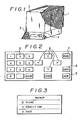
- FIG. 1 there is shown an apparatus according to the present invention which can be accommodated on a desk.
- the apparatus comprises an enclosure 1 having dimensions equivalent to an analyzing balance normally used in a laboratory, and a cover 2 is provided so as to close the whole surface of the enclosure 1.
- the cover 2 is made of transparent or translucent acrylic resin or the like and thus is see-through so as to make the interior of the enclosure 1 visible.
- the cover 2 preferably acts as an anti-radiation screen, e.g. against ⁇ rays, thus enhancing safety when a radiated sample is used.
- a display 3 and a keyboard 4 are provided on a lower portion of the front of the enclosure 1.
- the keyboard 4 comprises digit keys 0 to 9 for inputting a number of samples, conditions and other matters; cursor keys 6 for shifting a cursor indicated on the display 3 upwardly, downwardly, and to the left and right; a menu key 7 for selecting an input mode; a start key 8; and a top key 9 for controlling operation of the apparatus.
- Figure 3 shows a menu which constitutes one example of what may be displayed on the display 3.
- the cursor is shown as flickering on "1" in Figure 3.
- Figure 4 shows a cross section of an apparatus similar to that of Figure 1.
- An operating part of the apparatus of Figure 4 comprises roughly a dispensing part which is provided at the front of the apparatus.
- a temperature processing part and a part for holding samples are partioned by a panel 10.
- the apparatus has three slidably mounted stages or tables, namely a first or plate stage 11, a third or tip stage 12, and a second or reagent stage 13 in that order from the top.
- a tip stand 16 holding a plurality of tips, or apertured conical members, 15 thereon and a waste tip cell 17 for holding used tips 15 are mounted on the tip stage 12.
- the reagent cells 18 are arranged to be cooled by a thermo-module 23 mounted between a cooling fan 20 provided with a fan member 20 a and a cooler 22 sealed by the reagent door 21.
- the arrangement is such that the plate stage 11, the tip stage 12 and the reagent stage 13 are all moved by sliding them between the reagent dispensing part and the temperature treating and sample holding part of the apparatus by a sliding mechanism which is not shown in Figure 4.
- a closable door 24 is provided on each of them.
- An upper heater 25 and a lower heater 26 are provided on the temperature treating and sample holding part at vertically spaced positions corresponding to the positions of the upper and lower sides of the microplate 14 at the time when the plate stage 11 is at the end of its use.
- the upper heater 25 and the lower heater 26 are mounted on arms 28 which can be moved vertically about support points 27.
- a cam 30 mounted on a cam driving motor 29 is arranged to position the upper heater 25 and the lower heater 26 vertically through the arms 28.
- the cam 30 drives either the upper heater 25 or the lower heater 26 only according to its angular position.
- a pipetter 31 is mounted on a horizontal shaft guide rail 32 so that it can be slidably moved horizontally in a transverse direction.
- the horizontal shaft guide rail 32 is mounted on a vertical shaft guide rail 33 so that it can be slidably moved in a vertical direction.
- An electrical system for controlling the driving part and the temperature processing part of the apparatus comprises a motor drive unit 34 which is mounted on the upper portion of the apparatus; a power unit 35 and a control unit 36 which are mounted on the rear portion of the apparatus; and a temperature regulating unit 37 which is mounted on the bottom portion of the apparatus.
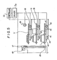
- FIG. 5 is a block diagram of the driving system.
- the plate stage 11, the tip stage 12 and the reagent stage 13 are arranged to be slidably moved by a plate stage motor 38, a tip stage motor 39 and a reagent stage motor 40 respectively through a respective timing belt 43 entrained around a motor pulley 41 and a guide roller 42.
- a light-obstructing plate or douser 44 is mounted on each timing belt 43, and a starting point or origin and an overload point can be detected by preventing light from reaching an origin sensor 45 and a limit sensor 46 respectively which are photo-interrupting type photo sensors.
- the pipetter 31 is driven by a pipetter motor 47 to suck and discharge a liquid and is slidably moved on the horizontal shaft guide rail 32 by an horizontal shaft guide rail 32 by an horizontal shaft motor 48.
- the horizontal shaft rail guide 32 is slidably moved along the vertical shaft guide rail 33 by a vertical shaft motor 49.
- the cam driving motor 29, the plate stage motor 38, the tip stage motor 39, the reagent stage motor 40, the pipetter motor 47, the horizontal shaft motor 48 and the vertical shaft motor 49 are driven by the driver or motor drive unit 34 according to signals from the controller or control unit 36. Each sensor signal is inputted to the controller 36 for processing thereby.
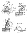
- FIG. 6 is a sectional view of a pipetter which may be used in an apparatus according to the present invention.
- the pipetter comprises a movable base 50 which is slidably mounted for horizontal sliding movement on the horizontal shaft guide rail 32, the movable base 50 having a vertically extending guide rail 51 on another face; a pipetter frame 52 which is slidably mounted for vertical movement on the guide rail 51; a needle guide 53 which is fixed on the pipetter frame 52 for frictionally holding a tip 15 thereon; a needle 54 which constitutes a syringe in association with the needle guide 53 and the tip 15 held thereon; an O-ring 55 for sealing the space between the pipetter frame 52 and the needle 54; a plate 56 for retaining the O-ring 55; a moving bed or support member 57 for moving the needle 54 axially of the tip, the moving bed 57 having a screw hole; a vertically extending guide rail 58, which is fixed on the pipette frame 52, for guiding vertical sliding movement
- Figure 7 illustrates the relationship between the pipetter 31 and the tip stand 16 at the time of inserting a tip 15 on the needle guide 53.
- the horizontal shaft motor 48 ( Figure 5) is driven so as to move the needle guide 53 of the pipetter 31 to a position in which it is located above a tip 15.
- the vertical shaft motor 49 ( Figure 5) is driven successively so as to move the pipetter 31 downwardly until the second sensor plate 67 obstructs light falling on the second photosensor 68.
- the pipetter 31 is then fed further down after the needle guide 53 is inserted into the tip 15 and comes into contact with the latter.
- the pipetter frame 52 is then slidably moved upwardly relatively to the movable base 50 and the first sensor plate 62 is moved away from the first photosensor 63.
- the first photosensor 63 is actuated to detect the contact of the tip 15 with the needle guide 53.
- the pipetter 31 If the pipetter 31 is to be moved downwardly thereafter, a pressure is applied by the pressurising mechanism 64. Thus, if the pipetter 31 is moved downwardly continuously, the tip 15 is inserted at a pressure proportional to the distance of descent after having come in contact with the needle guide 53.
- the second sensor plate 67 When an arbitrary pressure is reached, that is, when the pipetter 31 has descended by a predetermined distance (A), the second sensor plate 67 obstructs light to the second photosensor 68 and thereby detects that the tip 15 has been inserted at a predetermined pressure.
- the vertical shaft motor 49 stops. When the insertion of the tip 15 is over, the vertical shaft motor 49 rotates so that the pipetter 31 ascends, and the operation for tip insertion ends.
- the degree of insertion of the needle guide 53 in the tip 15 may be kept uniform irrespective of variations in the tip size. Further, an excessive load will never be applied to the pipetter 31 and the motor 49.
- Figure 8 illustrates the relationship between the pipetter 31 and the reagent cell 18 when the tip 15 has been inserted into the reagent cell 18.
- the horizontal shaft motor 48 ( Figure 5) is driven so as to move the tip 15 to a position where it is located above the reagent cell 18.
- the vertical shaft motor 49 ( Figure 5) is then driven successively so as to move the pipetter 31 downwardly until the first photosensor 63 detects the contact of the tip 15 with the bottom of the reagent cell 18.
- the pipetter motor 47 of the pipetter 31 is rotated a predetermined amount clockwise as viewed from the top.
- the needle 54 therefore ascends a predetermined amount.
- the pressure in the space of the tip 15 becomes negative with respect to the atmospheric pressure, and a predetermined amount of the reagent in the cell 18 is sucked out from the latter and into the tip 15.
- the vertical shaft motor 49 is driven so as to move the pipetter 31 upwards and the operation for effecting the suction ends.
- the pipetter frame 52 and the guide rail 51 are in contact with each other so as to permit vertical sliding motion of the pipetter frame 52.
- the pipetter frame 52 is in contact under gravity with a projection 50 a of the movable base 50.
- the first photosensor 63 fixed on the movable base 50 is capable of discriminating as to whether or not an object is present between a light emitting part and light receiving part of the photosensor 63.
- the first sensor plate 62 which is fixed on the pipetter frame 52, at this time obstructs a gap between the light emitting part and the light receiving part of the first photosensor 63.
- the pipetter frame 52 cannot be moved downwardly.
- the movable base 50 keeps moving downwardly unless the vertical shaft motor 49 which moves the movable base 50 stops.
- the relative positioning between the pipetter frame 52 and the movable base 50 is displaced by a dimension B as shown in Figure 8. That is, a displacement may arise in the positional relationship between the first sensor plate 62 and the adjacent first photosensor 63. Then, the time will come when the sensor plate 62 comes out of the gap between the light emitting part andthe light receiving part of the first photosensor 63.
- a signal will be transmitted to a controller (not shown) from the first photosensor 63, and the controller will issue a rotation stop command to the vertical shaft motor 49.
- the motor 49 therefore comes to a stop, and the nose portion of the tip 15 may come in contact with the bottom portion of the reagent cell 18 with a pressure determined by the weight of the pipetter frame 52 and other parts associated therewith.
- Figure 9 illustrates two modes of electrical operation which respectively depend on the positional relationship between the sensor plate 62 and the first photosensor 63.
- An LED 69 and a photo-transistor 70 shown in Figure 9 are equivalent to the first photosensor 63 of Figure 6.
- a current will not flow between the collector and the emitter of the photo-transistor 70 when a gap between the LED 69 and the photo-transistor 70 is obstructed by the plate 62.
- One input voltage of a two-input AND element 71 is Vcc, and a motor drive pulse signal, appears directly on the output.
- the motor drive pulse signal drives the motor 49 through a motor driver 72.
- a current flows between the collector and the emitter of the photo-transistor 70, and one input voltage of the AND element 71 will be at ground level.
- the output becomes a direct current regardless of the other input, and hence the drive signal is not inputted to the motor 49.
- the operation of the motor 49 is controlled according to whether or not an object is present in the gap between the LED 69 and the photo-transistor 70.
- the positional relationship between the nose portion of the tip 15 and the reagent cell 18 may be kept constant irrespective of the shape of the reagent cell and of any error in the shape of the pipetter. Further, the contact of the tip 15 with the test tube constituting the cell 18 may be such as to prevent liquid from mixing in, thereby ensuring precise discharge and suction.
- the upper heater 25 is shown as comprising an upper heating element or plate 74 which is tightly secured to the upper surface of an upper heating or temperature soaking plate 73.
- the upper heating element 74 is covered by an insulating material 75 thereon, and the upper heating plate 73 has a resilient conductive plate 76, e.g. of conductive rubber, on its lower surface.
- the lower heater 26 comrpises a lower heating element or plate 78 which is tightly secured on the lower surface of a lower heating or temperature soaking plate 77.
- the lower heating element 78 is covered by an insulating material 79 from below.
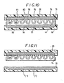
- Figure 10 shows the state in which the micro-plate 14 is sandwiched between the upper heater 25 and the lower heater 26 so as to be heated.
- the upper heater 25 and the lower heater 26 are controlled so as to be at the same set temperature, a vertical temperature gradient between the two heaters can be minimized, and the precision and accuracy of the temperature control of a liquid in the micro-plate 14 can be enhanced.
- the recesses or wells 80 in the micro-plate 14 are covered by the resilient plate 76 so as to seal the top of the micro-plate 14, thereby raising the pressure of the space in the wells 80, whereby any evaporation of liquid 81 in the wells 80 can be decreased.
- Figure 11 shows the state in which the lower heater 26 is detached from the lower surface of the micro-plate 14 to cool the latter while the upper surface of the micro-plate 14 remains pressed against the upper heater plate 25.
- the cooling effected in the state of Figure 11 is that from a state where the upper heater 25, the micro-plate 14 and the lower heater 26 are heated almost to the same temperature. Accordingly, the cooling rate of the liquid 81 in the micro-plate 14 is higher than the cooling rate of the upper heater 25. Therefore the liquid vaporized in the space in the well 80 can be cooled without settling on the upper surface of the upper heater plate 25.
- a mechanism for the positional control of the upper heater 25, the microplate 14 and the lower heater 26 is constituted by the cam driving motor 29.
- the construction shown in Figures 10 and 11 is effective in enhancing the precision and accuracy of the temperature control of the micro-plate 14 when the latter is sandwiched and heated between the upper heater 25 and the lower heater 26, and is also effective in minimizing loss of liquid in the micro-plate 14 after the heating is over and the lower heater 26 has been moved away from the lower surface of the micro-plate 14 for cooling purposes.
- Figure 12 illustrates the operation of the apparatus of Figure 4.
- the example illustrated in Figure 12 relates to an enzyme reaction process for analyzing a DNA base sequence according to the method of Sanger et al (Sanger, F., Nicklen, S. and Coulson A.R., "DNA sequencing with chain terminating inhibitors. " Proc Nat Acad. Sci USA 74 , 5463-5467 (1977)).
- the process is started by introducing samples into the recesses 80 in the micro-plate 14 on the plate stage 11.
- the tip stage 12 opens the door 24 so as to come out of the dispensing part of the apparatus.
- the pipetter 31 descends along the vertical shaft guide rail 33, and the tip 15 is installed.
- the pipetter 31 is lifted and the tip stage 12 is held in position.
- the reagent stage 13 is slidably moved to the dispensing part of the apparatus, and the pipetter 31 is moved downwardly to suck a buffer solution in the reagent cell 18. Then the pipetter 31 is lifted, the reagent stage 13 is held in position, and the plate stage 11 is drawn out. The pipetter 31 is kept descending until it comes in contact with the bottom of a recess 80 in the micro-plate 14. The pipetter motor 47 is driven so as to lift the pipetter 31 slowly, and thus a very small quantity of liquid is discharged successively into the recesses 80 of the micro-plate 14.
- the plate stage 11 is held in position, the tip stage 12 is drawn out, the tip on the nose of the pipetter 31 is caught on the waste tip cell 17 and is thus discharged into the waste tip cell 17.
- a primer solution is dispensed into the recesses in the micro-plate 14 through a simlar operation.
- the plate stage 11 is held in position, and the upper heater 25 and the lower heater 26 are driven by the cam driving motor 29 to sandwich the micro-plate 14 vertically through the cam 30 and the arm 28, so that the micro-plate 14 can be given a thermal treatment.
- the cam 30 is rotated to detach the micro-plate 14 from the upper heater 25 and the lower heater 26, and the next operation ensues.
- Operations for dispensing an isotope, a synthesizing enzyme and a mixture of monomers are carried out in a similar way and heating is effected, e.g. at 37°C for 15 minutes, to produce an enzyme reaction.
- a chase mixture and a dye solution are dispensed and heating is effected, e.g. at 90°C for 3 minutes.
- the product obtained as above is subjected to electrophoresis and then analyzed.
- a reagent such as an enzyme or the like which is unstable to heat can thus be retained for a long period of time, and the temperature environment necessary for the reaction of such an enzyme or the like can be produced. Further, since the space occupied by the apparatus is minimized, its installation on a desk will not hinder other work incidental thereto.
Abstract
Description
- This invention relates to an apparatus for carrying out a liquid reaction and, although the invention is not so restricted, it relates more particularly to an apparatus for automatically carrying out a liquid reaction in a laboratory or sample treatment, e.g. a reaction in which there is a very small quantity of a liquid sample and of a reagent, the apparatus employing an automated pipetter.
- In the biochemical field, many enzyme reaction processes are used to analyze biochemical samples such as protein and nucleic acid in a laboratory.
- Such enzyme reaction processes are composed of numerous repetitions of treating a very small quantity of liquid and thermally treating the latter at a precise temperature. Conventionally, such enzyme reaction processes are carried out manually by laboratory staffs and are therefore very tedious to perform.
- In recent years, sample preparation processes have attempted to carry out the processes by robots instead of by human beings. Experimental instruments, reagents and a robotic arm capable of manipulating sample tubes and syringes have been placed on a desk and the robotic arm has been controlled so as to carry out the sample preparation processes by using experimental instruments and reagents. F.H.Zenie et al described in detail such a robotic approach to automated sample preparation in AMERICAN LABORATORY, June 1982, pages 96-104.
- The robotic approach suggested in the prior art involves disposing the experimental instruments and reagents on a plane, and thus requires a large space for installation. Accordingly, once installed, the robot system occupies almost all the space on the desk, thus leaving no space for other apparatus. Further, reagents such as enzymes which are unstable at room temperature cannot be kept on the desk, and therefore the process is particularly unsuitable for the treatment of enzymes and the like.
- According, therefore, to the present invention, there is provided apparatus for carrying out a liquid reaction characterised by a first slidably mounted stage adapted to carry a sample cell or cells; a second slidably mounted stage adapted to carry a reagent cell or cells; pipetting means for sucking a reagent from a reagent cell and discharging it into a sample cell; means for sliding the first and second stages horizontally to and from positions in which a sample cell and a reagent cell are respectively in vertical alignment with the pipetting means; and means for effecting vertical sliding movement of the pipetting means into and out of a position or positions in which reagent may be sucked from a reagent cell and discharged into a sample cell.
- Preferably, heating means are provided for heating a sample cell carried by the first stage. Thus the heating means may comprise an upper heating plate for heating an upper surface of a sample cell; and a lower heating plate for heating a lower surface of the sample cell. The heating means may moreover comprise first contact means for establishing heat-transmitting contact between the upper heating plate and the upper surface of the sample cell and second contact means for establishing heat-transmitting contact between the lower heating plate and the lower surface of the sample cell.
- Control means may be provided for maintaining the upper and lower heating plates in heat-transmitting contact between the lower heating plate and the lower surface of the sample cell and for removing the lower heating plate from the sample cell while leaving the upper heating plate in heat-transmitting contact therewith.
- Cooling means may be provided for cooling the reagent cell or cells.
- The pipetting means may be carried by a frame which is mounted for vertical sliding movement on a horizontally movable base,means being provided for effecting vertical movement of the frame and horizontal movement of the base.
- The pipetting means may comprise a needle guide carried by the frame and a needle which is slidably mounted in the needle guide and is carried by a support member, the support member being mounted for vertical sliding movement on the frame, means being provided for effecting said vertical sliding movement.
- Detecting means may be provided for detectng the vertical position of the frame and for sending a detection signal to a control means for stopping movement of the frame.
- The apparatus may have a third slidably mounted stage which is adapted to support at least one conical member which can be mounted on the pipetting means, means being provided for sliding the third stage horizontally to and from a position in which a conical member is in vertical alignment with the pipetting means.
- In its preferred form, the apparatus of the present invention provides an automatic liquid reactor which occupies little space on a desk, which is capable of retaining unstable reagents such as enzymes therein for a long period, and whose operation is very simple and easy.
- In its preferred form, moreover, the apparatus employs two stages which are capable of sliding horizontally and along axes. A micro-plate which has a plurality of recesses in rows is placed in the first stage and reagent bottles are placed on the second stage. A pipetter is supported both on a horizontal shaft guide rail operating slidably horizontally and along an axis perpendicular to the axes along which the two stages slide. The horizontal shaft guide rail is supported on a vertical shaft guide rail so as to operate slidably in a vertical direction. Thus the pipetter may be moved in a plane perpendicular to the direction in which the two stages slide. When reagents are to be sucked from the reagent bottles, the second stage is moved so that a reagent bottle is disposed below the pipetter and the pipetter is moved downwardly into the reagent bottle to suck the reagent. When the reagent is to be discharged, the first stage is moved so that the microplate is disposed below the pipetter and the pipetter is moved downwardly into a recess to discharge the reagent thereby dispensing a reagent efficiently and minimizing the space required for installation.
- The invention is illustrated, merely by way of example, in the accompanying drawings, in which:-
- Figure 1 is a perspective view of an apparatus for carrying out a liquid reaction according to the present invention;
- Figure 2 is a pictorial view of a keyboard of the apparatus shown in Figure 1;
- Figure 3 is a pictorial view of a menu which may appear on a display of the apparatus shown in Figure 1;
- Figure 4 is a schematic cross section of an apparatus for carrying out a liquid reaction according to the present invention;
- Figure 5 is a block diagram of a driving system of the apparatus of Figure 4;
- Figure 6 is a cross section of a pipetter which may be used in the apparatus of Figure 4;
- Figure 7 is a cross section of a pipetter of Figure 6 showing a needle guide thereof introduced into a tip;
- Figure 8 is a cross-section of the pipetter of Figure 6 showing the arrangement of the parts during the sucking of reagent;
- Figure 9 illustrates a circuit block diagram of a photosensor shown in Figure 7;
- Figure 10 is a cross sectional view of an upper heater and a lower heater shown in Figure 4 with a microplate sandwiched between two heaters;
- Figure 11 is a view similar to Figure 10 but showing the lower heater moved from the position illustrated in Figure 10; and
- Figure 12 is a flow diagram illustrating the operation of the apparatus of Figure 4.
- In Figure 1 there is shown an apparatus according to the present invention which can be accommodated on a desk. The apparatus comprises an
enclosure 1 having dimensions equivalent to an analyzing balance normally used in a laboratory, and acover 2 is provided so as to close the whole surface of theenclosure 1. Thecover 2 is made of transparent or translucent acrylic resin or the like and thus is see-through so as to make the interior of theenclosure 1 visible. Thecover 2 preferably acts as an anti-radiation screen, e.g. against β rays, thus enhancing safety when a radiated sample is used. Adisplay 3 and akeyboard 4 are provided on a lower portion of the front of theenclosure 1. - One example of the
keyboard 4 is shown in Figure 2. Thekeyboard 4 comprisesdigit keys 0 to 9 for inputting a number of samples, conditions and other matters;cursor keys 6 for shifting a cursor indicated on thedisplay 3 upwardly, downwardly, and to the left and right; amenu key 7 for selecting an input mode; astart key 8; and atop key 9 for controlling operation of the apparatus. - Figure 3 shows a menu which constitutes one example of what may be displayed on the
display 3. The cursor is shown as flickering on "1" in Figure 3. - Figure 4 shows a cross section of an apparatus similar to that of Figure 1. An operating part of the apparatus of Figure 4 comprises roughly a dispensing part which is provided at the front of the apparatus. A temperature processing part and a part for holding samples are partioned by a
panel 10. - The apparatus has three slidably mounted stages or tables, namely a first or
plate stage 11, a third ortip stage 12, and a second orreagent stage 13 in that order from the top. Amicroplate 14,having a plurality of rows ofsmall recesses 80 which constitute sample cells, is mounted on theplate stage 11. - A tip stand 16 holding a plurality of tips, or apertured conical members, 15 thereon and a
waste tip cell 17 for holding usedtips 15 are mounted on thetip stage 12. - A reagent stand 19, with a plurality of reagent cells or
bottles 18 disposed thereon, is mounted on thereagent stage 13, and areagent door 21 is mounted at the front of thereagent stage 13. Thereagent cells 18 are arranged to be cooled by a thermo-module 23 mounted between acooling fan 20 provided with a fan member 20a and acooler 22 sealed by thereagent door 21. - The arrangement is such that the
plate stage 11, thetip stage 12 and thereagent stage 13 are all moved by sliding them between the reagent dispensing part and the temperature treating and sample holding part of the apparatus by a sliding mechanism which is not shown in Figure 4. In order to ensure that thepanel 10 acts as a perfect partition when theplate stage 11 and thetip stage 12 shift to the temperature treating and sample holding part, aclosable door 24 is provided on each of them. - An
upper heater 25 and alower heater 26 are provided on the temperature treating and sample holding part at vertically spaced positions corresponding to the positions of the upper and lower sides of themicroplate 14 at the time when theplate stage 11 is at the end of its use. Theupper heater 25 and thelower heater 26 are mounted onarms 28 which can be moved vertically aboutsupport points 27. - A
cam 30 mounted on acam driving motor 29 is arranged to position theupper heater 25 and thelower heater 26 vertically through thearms 28. Thecam 30 drives either theupper heater 25 or thelower heater 26 only according to its angular position. - In the reagent dispensing part, a pipetter 31 is mounted on a horizontal
shaft guide rail 32 so that it can be slidably moved horizontally in a transverse direction. The horizontalshaft guide rail 32 is mounted on a verticalshaft guide rail 33 so that it can be slidably moved in a vertical direction. - An electrical system for controlling the driving part and the temperature processing part of the apparatus comprises a
motor drive unit 34 which is mounted on the upper portion of the apparatus; apower unit 35 and acontrol unit 36 which are mounted on the rear portion of the apparatus; and atemperature regulating unit 37 which is mounted on the bottom portion of the apparatus. - Figure 5 is a block diagram of the driving system. The
plate stage 11, thetip stage 12 and thereagent stage 13 are arranged to be slidably moved by aplate stage motor 38, atip stage motor 39 and areagent stage motor 40 respectively through arespective timing belt 43 entrained around amotor pulley 41 and aguide roller 42. A light-obstructing plate or douser 44 is mounted on eachtiming belt 43, and a starting point or origin and an overload point can be detected by preventing light from reaching anorigin sensor 45 and alimit sensor 46 respectively which are photo-interrupting type photo sensors. - The pipetter 31 is driven by a
pipetter motor 47 to suck and discharge a liquid and is slidably moved on the horizontalshaft guide rail 32 by an horizontalshaft guide rail 32 by anhorizontal shaft motor 48. The horizontalshaft rail guide 32 is slidably moved along the verticalshaft guide rail 33 by avertical shaft motor 49. - The
cam driving motor 29, theplate stage motor 38, thetip stage motor 39, thereagent stage motor 40, thepipetter motor 47, thehorizontal shaft motor 48 and thevertical shaft motor 49 are driven by the driver ormotor drive unit 34 according to signals from the controller orcontrol unit 36. Each sensor signal is inputted to thecontroller 36 for processing thereby. - Figure 6 is a sectional view of a pipetter which may be used in an apparatus according to the present invention. The pipetter comprises a movable base 50 which is slidably mounted for horizontal sliding movement on the horizontal shaft guide rail 32, the movable base 50 having a vertically extending guide rail 51 on another face; a pipetter frame 52 which is slidably mounted for vertical movement on the guide rail 51; a needle guide 53 which is fixed on the pipetter frame 52 for frictionally holding a tip 15 thereon; a needle 54 which constitutes a syringe in association with the needle guide 53 and the tip 15 held thereon; an O-ring 55 for sealing the space between the pipetter frame 52 and the needle 54; a plate 56 for retaining the O-ring 55; a moving bed or support member 57 for moving the needle 54 axially of the tip, the moving bed 57 having a screw hole; a vertically extending guide rail 58, which is fixed on the pipette frame 52, for guiding vertical sliding movement of the moving bed 57; a feed screw 59 for feeding the moving bed 57 vertically, the feed screw 59 being in threaded engagement with the screw hole of the moving bed 57: the pipetter motor 47 which is fixed on the pipetter frame 52 and which is arranged to rotate the feed screw 59; a coupling 61 for transferring the torque of the pipetter motor 47 to the feed screw 59; a first sensor plate 62, secured to the pipetter frame 52 for detecting that the needle guide 53 has come in contact with a tip 15 or with the bottom of a reagent cell 18, the final sensor plate 62 cooperating with a first photosensor 63 provided on the movable base 50; a pressurising mechanism 64, fixed on the movable base 50, for pushing the movable base 50, the pressurising mechanism 64 including a push pin 65 for contacting the pipetter frame 52 and a spring 66 for applying a pressure to the push pin 65; and a second sensor plate 67, fixed on the pipetter frame 52, for detecting that the pipetter frame 52 has been slidably moved to a predetermined extent, the second sensor plate 67 cooperating with a second photo sensor 68 fixed on the movable base 50.
- Figure 7 illustrates the relationship between the pipetter 31 and the tip stand 16 at the time of inserting a
tip 15 on theneedle guide 53. First, the horizontal shaft motor 48 (Figure 5) is driven so as to move theneedle guide 53 of the pipetter 31 to a position in which it is located above atip 15. The vertical shaft motor 49 (Figure 5) is driven successively so as to move the pipetter 31 downwardly until thesecond sensor plate 67 obstructs light falling on thesecond photosensor 68. The pipetter 31 is then fed further down after theneedle guide 53 is inserted into thetip 15 and comes into contact with the latter. - The
pipetter frame 52 is then slidably moved upwardly relatively to themovable base 50 and thefirst sensor plate 62 is moved away from thefirst photosensor 63. Thus thefirst photosensor 63 is actuated to detect the contact of thetip 15 with theneedle guide 53. - If the pipetter 31 is to be moved downwardly thereafter, a pressure is applied by the
pressurising mechanism 64. Thus, if the pipetter 31 is moved downwardly continuously, thetip 15 is inserted at a pressure proportional to the distance of descent after having come in contact with theneedle guide 53. When an arbitrary pressure is reached, that is, when the pipetter 31 has descended by a predetermined distance (A), thesecond sensor plate 67 obstructs light to thesecond photosensor 68 and thereby detects that thetip 15 has been inserted at a predetermined pressure. Thus, thevertical shaft motor 49 stops. When the insertion of thetip 15 is over, thevertical shaft motor 49 rotates so that the pipetter 31 ascends, and the operation for tip insertion ends. - According to this operation, the degree of insertion of the
needle guide 53 in thetip 15 may be kept uniform irrespective of variations in the tip size. Further, an excessive load will never be applied to the pipetter 31 and themotor 49. - Figure 8 illustrates the relationship between the pipetter 31 and the
reagent cell 18 when thetip 15 has been inserted into thereagent cell 18. - First, the horizontal shaft motor 48 (Figure 5) is driven so as to move the
tip 15 to a position where it is located above thereagent cell 18. The vertical shaft motor 49 (Figure 5) is then driven successively so as to move the pipetter 31 downwardly until thefirst photosensor 63 detects the contact of thetip 15 with the bottom of thereagent cell 18. Simultaneously with thevertical shaft motor 49 stopping as a result of this detection, thepipetter motor 47 of the pipetter 31 is rotated a predetermined amount clockwise as viewed from the top. Theneedle 54 therefore ascends a predetermined amount. Consequently, the pressure in the space of thetip 15 becomes negative with respect to the atmospheric pressure, and a predetermined amount of the reagent in thecell 18 is sucked out from the latter and into thetip 15. When the suction is over, thevertical shaft motor 49 is driven so as to move the pipetter 31 upwards and the operation for effecting the suction ends. - Then, in the case of the operation for effecting the discharge of the reagent, the feed motion to the
needle 54 is merely reversed with respect to the suction operation described as above, and therefore will not be described further. - Next, there will be described in detail a mechanism for detecting contact of the
tip 15 with acell 18. Thepipetter frame 52 and theguide rail 51 are in contact with each other so as to permit vertical sliding motion of thepipetter frame 52. In the position of the parts shown in Figure 6, thepipetter frame 52 is in contact under gravity with aprojection 50a of themovable base 50. Thefirst photosensor 63 fixed on themovable base 50 is capable of discriminating as to whether or not an object is present between a light emitting part and light receiving part of thephotosensor 63. Thefirst sensor plate 62, which is fixed on thepipetter frame 52, at this time obstructs a gap between the light emitting part and the light receiving part of thefirst photosensor 63. Then, if the nose portion of thetip 15 comes into direct contact with thereagent cell 18, thepipetter frame 52 cannot be moved downwardly. However, since thepipetter frame 52 is slidable with respect to themovable base 50, themovable base 50 keeps moving downwardly unless thevertical shaft motor 49 which moves themovable base 50 stops. Then, the relative positioning between thepipetter frame 52 and themovable base 50 is displaced by a dimension B as shown in Figure 8. That is, a displacement may arise in the positional relationship between thefirst sensor plate 62 and the adjacentfirst photosensor 63. Then, the time will come when thesensor plate 62 comes out of the gap between the light emitting part andthe light receiving part of thefirst photosensor 63. In this case, a signal will be transmitted to a controller (not shown) from thefirst photosensor 63, and the controller will issue a rotation stop command to thevertical shaft motor 49. Themotor 49 therefore comes to a stop, and the nose portion of thetip 15 may come in contact with the bottom portion of thereagent cell 18 with a pressure determined by the weight of thepipetter frame 52 and other parts associated therewith. - Figure 9 illustrates two modes of electrical operation which respectively depend on the positional relationship between the
sensor plate 62 and thefirst photosensor 63. - An
LED 69 and a photo-transistor 70 shown in Figure 9 are equivalent to thefirst photosensor 63 of Figure 6. A current will not flow between the collector and the emitter of the photo-transistor 70 when a gap between theLED 69 and the photo-transistor 70 is obstructed by theplate 62. One input voltage of a two-input ANDelement 71 is Vcc, and a motor drive pulse signal, appears directly on the output. The motor drive pulse signal drives themotor 49 through amotor driver 72. On the other hand, when there is nothing present between theLED 69 and the photo-transistor 70, a current flows between the collector and the emitter of the photo-transistor 70, and one input voltage of the ANDelement 71 will be at ground level. Therefore, the output becomes a direct current regardless of the other input, and hence the drive signal is not inputted to themotor 49. As described, the operation of themotor 49 is controlled according to whether or not an object is present in the gap between theLED 69 and the photo-transistor 70. - The positional relationship between the nose portion of the
tip 15 and thereagent cell 18 may be kept constant irrespective of the shape of the reagent cell and of any error in the shape of the pipetter. Further, the contact of thetip 15 with the test tube constituting thecell 18 may be such as to prevent liquid from mixing in, thereby ensuring precise discharge and suction. - In Figures 10 and 11, the
upper heater 25 is shown as comprising an upper heating element orplate 74 which is tightly secured to the upper surface of an upper heating ortemperature soaking plate 73. Theupper heating element 74 is covered by an insulatingmaterial 75 thereon, and theupper heating plate 73 has a resilientconductive plate 76, e.g. of conductive rubber, on its lower surface. - The
lower heater 26 comrpises a lower heating element orplate 78 which is tightly secured on the lower surface of a lower heating ortemperature soaking plate 77. Thelower heating element 78 is covered by an insulatingmaterial 79 from below. - Figure 10 shows the state in which the micro-plate 14 is sandwiched between the
upper heater 25 and thelower heater 26 so as to be heated. In this case, since theupper heater 25 and thelower heater 26 are controlled so as to be at the same set temperature, a vertical temperature gradient between the two heaters can be minimized, and the precision and accuracy of the temperature control of a liquid in the micro-plate 14 can be enhanced. Further the recesses orwells 80 in the micro-plate 14 are covered by theresilient plate 76 so as to seal the top of the micro-plate 14, thereby raising the pressure of the space in thewells 80, whereby any evaporation ofliquid 81 in thewells 80 can be decreased. - Figure 11 shows the state in which the
lower heater 26 is detached from the lower surface of the micro-plate 14 to cool the latter while the upper surface of the micro-plate 14 remains pressed against theupper heater plate 25. The cooling effected in the state of Figure 11 is that from a state where theupper heater 25, the micro-plate 14 and thelower heater 26 are heated almost to the same temperature. Accordingly, the cooling rate of the liquid 81 in the micro-plate 14 is higher than the cooling rate of theupper heater 25. Therefore the liquid vaporized in the space in the well 80 can be cooled without settling on the upper surface of theupper heater plate 25. A mechanism for the positional control of theupper heater 25, themicroplate 14 and thelower heater 26 is constituted by thecam driving motor 29. - The construction shown in Figures 10 and 11 is effective in enhancing the precision and accuracy of the temperature control of the micro-plate 14 when the latter is sandwiched and heated between the
upper heater 25 and thelower heater 26, and is also effective in minimizing loss of liquid in the micro-plate 14 after the heating is over and thelower heater 26 has been moved away from the lower surface of the micro-plate 14 for cooling purposes. - Figure 12 illustrates the operation of the apparatus of Figure 4. The example illustrated in Figure 12 relates to an enzyme reaction process for analyzing a DNA base sequence according to the method of Sanger et al (Sanger, F., Nicklen, S. and Coulson A.R., "DNA sequencing with chain terminating inhibitors. "Proc Nat
Acad. Sci USA 74, 5463-5467 (1977)). The process is started by introducing samples into therecesses 80 in the micro-plate 14 on theplate stage 11. Thetip stage 12 opens thedoor 24 so as to come out of the dispensing part of the apparatus. Next, the pipetter 31 descends along the verticalshaft guide rail 33, and thetip 15 is installed. The pipetter 31 is lifted and thetip stage 12 is held in position. Thereagent stage 13 is slidably moved to the dispensing part of the apparatus, and the pipetter 31 is moved downwardly to suck a buffer solution in thereagent cell 18. Then the pipetter 31 is lifted, thereagent stage 13 is held in position, and theplate stage 11 is drawn out. The pipetter 31 is kept descending until it comes in contact with the bottom of arecess 80 in the micro-plate 14. Thepipetter motor 47 is driven so as to lift the pipetter 31 slowly, and thus a very small quantity of liquid is discharged successively into therecesses 80 of the micro-plate 14. Theplate stage 11 is held in position, thetip stage 12 is drawn out, the tip on the nose of the pipetter 31 is caught on thewaste tip cell 17 and is thus discharged into thewaste tip cell 17. A primer solution is dispensed into the recesses in the micro-plate 14 through a simlar operation. - Next, the
plate stage 11 is held in position, and theupper heater 25 and thelower heater 26 are driven by thecam driving motor 29 to sandwich the micro-plate 14 vertically through thecam 30 and thearm 28, so that the micro-plate 14 can be given a thermal treatment. - After the thermal treatment has been applied for a predetermined time, e.g. for 15 minutes at 60°C; the
cam 30 is rotated to detach the micro-plate 14 from theupper heater 25 and thelower heater 26, and the next operation ensues. Operations for dispensing an isotope, a synthesizing enzyme and a mixture of monomers are carried out in a similar way and heating is effected, e.g. at 37°C for 15 minutes, to produce an enzyme reaction. After this, a chase mixture and a dye solution are dispensed and heating is effected, e.g. at 90°C for 3 minutes. - The product obtained as above is subjected to electrophoresis and then analyzed.
- A reagent such as an enzyme or the like which is unstable to heat can thus be retained for a long period of time, and the temperature environment necessary for the reaction of such an enzyme or the like can be produced. Further, since the space occupied by the apparatus is minimized, its installation on a desk will not hinder other work incidental thereto.
Claims (11)
Applications Claiming Priority (8)
| Application Number | Priority Date | Filing Date | Title |
|---|---|---|---|
| JP254902/87 | 1987-10-09 | ||
| JP62254902A JP2657296B2 (en) | 1987-10-09 | 1987-10-09 | Micro liquid reactor |
| JP25490187A JPH0197865A (en) | 1987-10-09 | 1987-10-09 | Automatic pipette |
| JP254901/87 | 1987-10-09 | ||
| JP28042087A JPH01123154A (en) | 1987-11-06 | 1987-11-06 | Pipetter equipped with automatic chip inserting function |
| JP280420/87 | 1987-11-06 | ||
| JP5463/88 | 1988-01-13 | ||
| JP63005463A JP2662788B2 (en) | 1988-01-13 | 1988-01-13 | Microplate heating method and device |
Publications (3)
| Publication Number | Publication Date |
|---|---|
| EP0311440A2 true EP0311440A2 (en) | 1989-04-12 |
| EP0311440A3 EP0311440A3 (en) | 1989-10-25 |
| EP0311440B1 EP0311440B1 (en) | 1992-06-24 |
Family
ID=27454298
Family Applications (1)
| Application Number | Title | Priority Date | Filing Date |
|---|---|---|---|
| EP88309401A Expired - Lifetime EP0311440B1 (en) | 1987-10-09 | 1988-10-07 | Apparatus for carrying out a liquid reaction |
Country Status (3)
| Country | Link |
|---|---|
| US (1) | US5102623A (en) |
| EP (1) | EP0311440B1 (en) |
| DE (1) | DE3872341T2 (en) |
Cited By (20)
| Publication number | Priority date | Publication date | Assignee | Title |
|---|---|---|---|---|
| EP0388159A2 (en) * | 1989-03-15 | 1990-09-19 | Seiko Instruments Inc. | Apparatus for sealing liquid within cavities |
| DE3921393A1 (en) * | 1989-06-29 | 1991-01-10 | Lre Relais & Elektronik Gmbh | Appts. for automatic photometric analysis of e.g. blood - contains liq. specimen and reagent transfer devices and cuvette transport mechanism |
| EP0425690A1 (en) * | 1989-04-25 | 1991-05-08 | Kyoto Daiichi Kagaku Co., Ltd. | Method of detecting operation condition of a micropipette |
| EP0438883A2 (en) * | 1989-12-22 | 1991-07-31 | Beckman Instruments, Inc. | Heated cover device |
| WO1991017445A1 (en) * | 1990-05-10 | 1991-11-14 | Pb Diagnostic Systems, Inc. | Fluid dispensing system with optical locator |
| EP0488769A2 (en) * | 1990-11-29 | 1992-06-03 | The Perkin-Elmer Corporation | Thermal cycler for automatic performance of the polymerase chain reaction with close temperature control |
| EP0508531A2 (en) * | 1991-04-10 | 1992-10-14 | Johnson & Johnson Clinical Diagnostics, Inc. | Liquid dispensing using container bottom sensing |
| EP0590731A2 (en) * | 1992-09-30 | 1994-04-06 | Johnson & Johnson Clinical Diagnostics, Inc. | Analyser nozzle and method of detection of tip pick-up |
| EP0606961A1 (en) * | 1989-06-12 | 1994-07-20 | Johnson & Johnson Clinical Diagnostics, Inc. | Temperature control device for reaction vessel |
| EP0705424A1 (en) * | 1993-06-21 | 1996-04-10 | Boehringer Mannheim Corporation | Front end apparatus and method |
| US5516490A (en) * | 1993-04-19 | 1996-05-14 | Sanadi Biotech Group, Inc. | Apparatus for preventing cross-contamination of multi-well test plates |
| US5741463A (en) * | 1993-04-19 | 1998-04-21 | Sanadi; Ashok Ramesh | Apparatus for preventing cross-contamination of multi-well test plates |
| EP0955097A1 (en) * | 1998-05-04 | 1999-11-10 | F. Hoffmann-La Roche Ag | Thermal cycler having an automatically positionable cover |
| US6486401B1 (en) | 1999-02-22 | 2002-11-26 | Tekcel, Inc. | Multi well plate cover and assembly |
| WO2003064697A1 (en) * | 2002-01-30 | 2003-08-07 | Applera Corporation | Device and method for thermal cycling |
| EP1363737A1 (en) * | 2001-02-01 | 2003-11-26 | V & P Scientific, Inc. | Microarrayer |
| DE10120056B4 (en) * | 2000-06-13 | 2009-01-02 | Shimadzu Corp. | Automatic temperature control device |
| US7504241B2 (en) | 1990-11-29 | 2009-03-17 | Applied Biosystems, Llc | Thermal cycler for automatic performance of the polymerase chain reaction with close temperature control |
| US7976794B2 (en) | 2006-07-21 | 2011-07-12 | Stratec Biomedical Systems Ag | Positioning device for the positioning of pipettes |
| WO2019071232A1 (en) | 2017-10-06 | 2019-04-11 | Wyatt Technology Corporation | Method and apparatus to mitigate evaporation in high throughput measurements |
Families Citing this family (31)
| Publication number | Priority date | Publication date | Assignee | Title |
|---|---|---|---|---|
| JP2626738B2 (en) * | 1990-03-13 | 1997-07-02 | 三共株式会社 | Chemiluminescence detector |
| JPH049669A (en) * | 1990-04-26 | 1992-01-14 | Hitachi Ltd | Automatic sampling device for liquid sample |
| SG46491A1 (en) * | 1991-03-19 | 1998-02-20 | Hoffmann La Roche | Closure for reagent container |
| JPH05157684A (en) * | 1991-12-02 | 1993-06-25 | Seikagaku Kogyo Co Ltd | Absorptionmeter |
| FR2688313A1 (en) * | 1992-03-04 | 1993-09-10 | Marteau D Autry Eric | AUTOMATIC FILTERING AND IDENTIFICATION OF SAMPLES. |
| US5479969A (en) * | 1992-08-19 | 1996-01-02 | British Nuclear Fuels Plc | Apparatus for dispensing substances which are biologically hazardous |
| GB9217616D0 (en) * | 1992-08-19 | 1992-09-30 | British Nuclear Fuels Plc | Dispensing apparatus |
| US5356525A (en) * | 1993-04-16 | 1994-10-18 | Beckman Instruments, Inc. | Sample handling system |
| US5531964A (en) * | 1994-10-25 | 1996-07-02 | Compagnie Generale Des Matieres Nucleaires | Automated analysis chain |
| US5873394A (en) * | 1997-07-02 | 1999-02-23 | Cyberlab, Inc. | Automated sample preparation workstation for the vapor diffusion method of crystallization and method of preparation |
| FR2767583B1 (en) * | 1997-08-20 | 1999-10-22 | Junior Instruments | DEVICE FOR THE COLLECTION AND / OR INJECTION INSIDE A MOUTH SAMPLE TUBE |
| DE29720432U1 (en) * | 1997-11-19 | 1999-03-25 | Mwg Biotech Gmbh | robot |
| JPH11295323A (en) * | 1998-04-13 | 1999-10-29 | Matsushita Electric Ind Co Ltd | Automatic dispenser and its method |
| JP3587066B2 (en) * | 1998-10-12 | 2004-11-10 | 松下電器産業株式会社 | Automatic dispensing device |
| EP1129346A2 (en) * | 1998-10-16 | 2001-09-05 | Intelligent Automation Systems | Continuous processing automated workstation |
| AU2633100A (en) * | 1999-01-29 | 2000-08-18 | Genomic Instrumentation Services, Inc. | Robotic work station |
| US6325114B1 (en) * | 2000-02-01 | 2001-12-04 | Incyte Genomics, Inc. | Pipetting station apparatus |
| US6739448B1 (en) | 2000-02-01 | 2004-05-25 | Incyte Corporation | Method and apparatus for shuttling microtitre plates |
| JPWO2003055973A1 (en) * | 2001-12-26 | 2005-05-12 | オリンパス株式会社 | Reaction vessel and reaction vessel holding mechanism |
| US7846315B2 (en) * | 2002-01-28 | 2010-12-07 | Qiagen Sciences, Llc | Integrated bio-analysis and sample preparation system |
| WO2004001376A2 (en) * | 2002-06-20 | 2003-12-31 | Sention, Inc. | Apparatus for polynucleotide detection and quantitation |
| DE102004046740B4 (en) * | 2004-06-07 | 2006-07-06 | Aviso Gmbh Mechatronic Systems | Tool head for a device for the automatic isolation and treatment of cell clones |
| US7284453B2 (en) * | 2005-07-15 | 2007-10-23 | Beckman Coulter, Inc. | Method and apparatus for maximizing liquid aspiration from small vessels |
| DE202005014704U1 (en) * | 2005-09-16 | 2007-02-01 | C. Gerhardt Fabrik Und Lager Chemischer Apparate Gmbh & Co. Kg | Device for the preparation of oil compositions for aromatherapy |
| EP2191900B1 (en) | 2008-11-28 | 2016-03-30 | F. Hoffmann-La Roche AG | System and method for nucleic acids containing fluid processing |
| US9103782B2 (en) | 2008-12-02 | 2015-08-11 | Malvern Instruments Incorporated | Automatic isothermal titration microcalorimeter apparatus and method of use |
| JP5275182B2 (en) | 2009-09-11 | 2013-08-28 | 株式会社日立ハイテクノロジーズ | Dispensing device and analyzer |
| US20120028298A1 (en) * | 2010-07-28 | 2012-02-02 | Glenn Takayama | System and method for automated tissue slide processing and data management |
| US8951781B2 (en) | 2011-01-10 | 2015-02-10 | Illumina, Inc. | Systems, methods, and apparatuses to image a sample for biological or chemical analysis |
| CH708820A1 (en) | 2013-11-07 | 2015-05-15 | Tecan Trading Ag | Inkubationskassette. |
| WO2016073832A1 (en) * | 2014-11-07 | 2016-05-12 | Theranos, Inc. | Improved methods, devices, and systems for mixing fluids |
Citations (7)
| Publication number | Priority date | Publication date | Assignee | Title |
|---|---|---|---|---|
| US3650306A (en) * | 1970-09-18 | 1972-03-21 | Cooke Eng Co | Laboratory dispensing apparatus |
| USRE27756E (en) * | 1971-06-29 | 1973-09-11 | Automated incubation apparatus | |
| GB1528424A (en) * | 1975-12-30 | 1978-10-11 | Mueszeripari Muevek Lab | Apparatus for and a method of determination of influenza neuraminidase |
| US4478094A (en) * | 1983-01-21 | 1984-10-23 | Cetus Corporation | Liquid sample handling system |
| WO1986002168A1 (en) * | 1984-10-01 | 1986-04-10 | Cetus Corporation | Automated assay machine and assay tray |
| WO1987000083A1 (en) * | 1985-07-01 | 1987-01-15 | American Hospital Supply Corporation | Tray for analyzing system |
| WO1987006008A2 (en) * | 1986-03-26 | 1987-10-08 | Beckman Instruments, Inc. | Automated multi-purposse analytical chemistry processing center and laboratory work station |
Family Cites Families (2)
| Publication number | Priority date | Publication date | Assignee | Title |
|---|---|---|---|---|
| FR2097484A5 (en) * | 1970-07-08 | 1972-03-03 | Automatisme Cie Gle | |
| JPS59230162A (en) * | 1984-04-18 | 1984-12-24 | Hitachi Ltd | Automatic analyzing device |
-
1988
- 1988-10-07 DE DE8888309401T patent/DE3872341T2/en not_active Expired - Fee Related
- 1988-10-07 EP EP88309401A patent/EP0311440B1/en not_active Expired - Lifetime
- 1988-10-11 US US07/255,474 patent/US5102623A/en not_active Expired - Lifetime
Patent Citations (8)
| Publication number | Priority date | Publication date | Assignee | Title |
|---|---|---|---|---|
| US3650306A (en) * | 1970-09-18 | 1972-03-21 | Cooke Eng Co | Laboratory dispensing apparatus |
| USRE27756E (en) * | 1971-06-29 | 1973-09-11 | Automated incubation apparatus | |
| GB1528424A (en) * | 1975-12-30 | 1978-10-11 | Mueszeripari Muevek Lab | Apparatus for and a method of determination of influenza neuraminidase |
| US4478094A (en) * | 1983-01-21 | 1984-10-23 | Cetus Corporation | Liquid sample handling system |
| US4478094B1 (en) * | 1983-01-21 | 1988-04-19 | ||
| WO1986002168A1 (en) * | 1984-10-01 | 1986-04-10 | Cetus Corporation | Automated assay machine and assay tray |
| WO1987000083A1 (en) * | 1985-07-01 | 1987-01-15 | American Hospital Supply Corporation | Tray for analyzing system |
| WO1987006008A2 (en) * | 1986-03-26 | 1987-10-08 | Beckman Instruments, Inc. | Automated multi-purposse analytical chemistry processing center and laboratory work station |
Cited By (43)
| Publication number | Priority date | Publication date | Assignee | Title |
|---|---|---|---|---|
| EP0388159A2 (en) * | 1989-03-15 | 1990-09-19 | Seiko Instruments Inc. | Apparatus for sealing liquid within cavities |
| EP0388159A3 (en) * | 1989-03-15 | 1991-06-12 | Seiko Instruments Inc. | Apparatus for sealing liquid within cavities |
| EP0425690A1 (en) * | 1989-04-25 | 1991-05-08 | Kyoto Daiichi Kagaku Co., Ltd. | Method of detecting operation condition of a micropipette |
| EP0425690A4 (en) * | 1989-04-25 | 1992-03-18 | Kyoto Daiichi Kagaku Co., Ltd. | Method of detecting operation condition of a micropipette |
| EP0606961A1 (en) * | 1989-06-12 | 1994-07-20 | Johnson & Johnson Clinical Diagnostics, Inc. | Temperature control device for reaction vessel |
| DE3921393A1 (en) * | 1989-06-29 | 1991-01-10 | Lre Relais & Elektronik Gmbh | Appts. for automatic photometric analysis of e.g. blood - contains liq. specimen and reagent transfer devices and cuvette transport mechanism |
| EP0438883A2 (en) * | 1989-12-22 | 1991-07-31 | Beckman Instruments, Inc. | Heated cover device |
| US5552580A (en) * | 1989-12-22 | 1996-09-03 | Beckman Instruments, Inc. | Heated cover device |
| EP0438883A3 (en) * | 1989-12-22 | 1992-03-04 | Beckman Instruments, Inc. | Heated cover device |
| US5496517A (en) * | 1989-12-22 | 1996-03-05 | Beckman Instruments, Inc. | Laboratory workstation using thermal vaporization control |
| WO1991017445A1 (en) * | 1990-05-10 | 1991-11-14 | Pb Diagnostic Systems, Inc. | Fluid dispensing system with optical locator |
| US5141871A (en) * | 1990-05-10 | 1992-08-25 | Pb Diagnostic Systems, Inc. | Fluid dispensing system with optical locator |
| US7504241B2 (en) | 1990-11-29 | 2009-03-17 | Applied Biosystems, Llc | Thermal cycler for automatic performance of the polymerase chain reaction with close temperature control |
| EP0488769A3 (en) * | 1990-11-29 | 1993-05-26 | Perkin-Elmer Cetus Instruments | Thermal cycler for automatic performance of the polymerase chain reaction with close temperature control |
| US6015534A (en) * | 1990-11-29 | 2000-01-18 | The Perkin-Elmer Corporation | PCR sample tube |
| US5710381A (en) * | 1990-11-29 | 1998-01-20 | The Perkin-Elmer Corporation | Two piece holder for PCR sample tubes |
| US5475610A (en) * | 1990-11-29 | 1995-12-12 | The Perkin-Elmer Corporation | Thermal cycler for automatic performance of the polymerase chain reaction with close temperature control |
| EP0488769A2 (en) * | 1990-11-29 | 1992-06-03 | The Perkin-Elmer Corporation | Thermal cycler for automatic performance of the polymerase chain reaction with close temperature control |
| EP0810030A1 (en) * | 1990-11-29 | 1997-12-03 | The Perkin-Elmer Corporation | Apparatus and containers for performing polymerase chain reaction |
| US5602756A (en) * | 1990-11-29 | 1997-02-11 | The Perkin-Elmer Corporation | Thermal cycler for automatic performance of the polymerase chain reaction with close temperature control |
| EP0508531A2 (en) * | 1991-04-10 | 1992-10-14 | Johnson & Johnson Clinical Diagnostics, Inc. | Liquid dispensing using container bottom sensing |
| EP0508531A3 (en) * | 1991-04-10 | 1993-01-13 | Eastman Kodak Company | Liquid dispensing using container bottom sensing |
| EP0590731A3 (en) * | 1992-09-30 | 1994-09-28 | Eastman Kodak Co | Analyser nozzle and method of detection of tip pick-up |
| EP0590731A2 (en) * | 1992-09-30 | 1994-04-06 | Johnson & Johnson Clinical Diagnostics, Inc. | Analyser nozzle and method of detection of tip pick-up |
| US6258325B1 (en) | 1993-04-19 | 2001-07-10 | Ashok Ramesh Sanadi | Method and apparatus for preventing cross-contamination of multi-well test plates |
| US5516490A (en) * | 1993-04-19 | 1996-05-14 | Sanadi Biotech Group, Inc. | Apparatus for preventing cross-contamination of multi-well test plates |
| US5741463A (en) * | 1993-04-19 | 1998-04-21 | Sanadi; Ashok Ramesh | Apparatus for preventing cross-contamination of multi-well test plates |
| EP0705424A1 (en) * | 1993-06-21 | 1996-04-10 | Boehringer Mannheim Corporation | Front end apparatus and method |
| EP0705424A4 (en) * | 1993-06-21 | 1996-12-04 | Boehringer Mannheim Corp | Front end apparatus and method |
| EP0955097A1 (en) * | 1998-05-04 | 1999-11-10 | F. Hoffmann-La Roche Ag | Thermal cycler having an automatically positionable cover |
| US6197572B1 (en) | 1998-05-04 | 2001-03-06 | Roche Diagnostics Corporation | Thermal cycler having an automatically positionable lid |
| US6486401B1 (en) | 1999-02-22 | 2002-11-26 | Tekcel, Inc. | Multi well plate cover and assembly |
| DE10120056B4 (en) * | 2000-06-13 | 2009-01-02 | Shimadzu Corp. | Automatic temperature control device |
| EP1363737A1 (en) * | 2001-02-01 | 2003-11-26 | V & P Scientific, Inc. | Microarrayer |
| EP1363737A4 (en) * | 2001-02-01 | 2007-01-17 | V & P Scient Inc | Microarrayer |
| US6677151B2 (en) | 2002-01-30 | 2004-01-13 | Applera Corporation | Device and method for thermal cycling |
| WO2003064697A1 (en) * | 2002-01-30 | 2003-08-07 | Applera Corporation | Device and method for thermal cycling |
| US8993237B2 (en) | 2002-01-30 | 2015-03-31 | Applied Biosystems, Llc | Device and method for thermal cycling |
| US9889448B2 (en) | 2002-01-30 | 2018-02-13 | Applied Biosystems, Llc | Device and method for thermal cycling |
| US7976794B2 (en) | 2006-07-21 | 2011-07-12 | Stratec Biomedical Systems Ag | Positioning device for the positioning of pipettes |
| DE102006034245C5 (en) * | 2006-07-21 | 2014-05-28 | Stratec Biomedical Systems Ag | Positioning device for positioning pipettes |
| WO2019071232A1 (en) | 2017-10-06 | 2019-04-11 | Wyatt Technology Corporation | Method and apparatus to mitigate evaporation in high throughput measurements |
| EP3695212A4 (en) * | 2017-10-06 | 2021-07-28 | Wyatt Technology Corporation | Method and apparatus to mitigate evaporation in high throughput measurements |
Also Published As
| Publication number | Publication date |
|---|---|
| EP0311440A3 (en) | 1989-10-25 |
| DE3872341T2 (en) | 1992-12-10 |
| US5102623A (en) | 1992-04-07 |
| EP0311440B1 (en) | 1992-06-24 |
| DE3872341D1 (en) | 1992-07-30 |
Similar Documents
| Publication | Publication Date | Title |
|---|---|---|
| EP0311440B1 (en) | Apparatus for carrying out a liquid reaction | |
| EP1506413B1 (en) | Automated system for isolating, amplyifying and detecting a target nucleic acid sequence | |
| US5443790A (en) | Device for automatically analyzing samples | |
| US5650122A (en) | Automated patient sample analysis instrument having tubes and reaction wells washing apparatus | |
| JP3068184B2 (en) | Equipment for carrying out biochemical reactions | |
| WO2022237181A1 (en) | Dna and rna nucleic acid co-extraction and detection system | |
| KR101917402B1 (en) | Automatic response/light measurement device and method therefor | |
| EP0210014A2 (en) | Automated liquid handling apparatus and process with plate handler | |
| EP2263802A1 (en) | System and method for dispensing fluids | |
| EP0138205A1 (en) | Bi-directional liquid sample handling system | |
| KR20180051433A (en) | A high throughput system for performing assays using electrochemiluminescence, including a consumable agitation device | |
| DE10011547T1 (en) | System and method for incubating the contents of a reaction vessel | |
| JPH0854401A (en) | Optical sensor | |
| US20230250418A1 (en) | Three-degree-of-freedom library preparation cassette and method using the same | |
| EP0238582B1 (en) | Method for immunological determinations | |
| CN115637213A (en) | A hot lid device and PCR appearance for PCR appearance | |
| JP2657296B2 (en) | Micro liquid reactor | |
| CN116136541A (en) | Automated analysis system for processing biological samples | |
| EP1615037A1 (en) | An apparatus for liquid handling with multiple transfer tools | |
| JPS62182664A (en) | Automatic liquid treating device and method with plate treater | |
| CN217628334U (en) | Biological chip all-in-one machine | |
| CN217112092U (en) | Full-automatic homogeneous phase chemiluminescence instant detection analyzer | |
| JPS6379072A (en) | Automatic specimen introducing apparatus | |
| CN114544602A (en) | Full-automatic homogeneous phase chemiluminescence instant detection analyzer and control method thereof | |
| CN114441510A (en) | POCT full-automatic chemiluminescence device based on multi-channel parallel pretreatment technology |
Legal Events
| Date | Code | Title | Description |
|---|---|---|---|
| PUAI | Public reference made under article 153(3) epc to a published international application that has entered the european phase |
Free format text: ORIGINAL CODE: 0009012 |
|
| AK | Designated contracting states |
Kind code of ref document: A2 Designated state(s): DE FR GB |
|
| PUAL | Search report despatched |
Free format text: ORIGINAL CODE: 0009013 |
|
| AK | Designated contracting states |
Kind code of ref document: A3 Designated state(s): DE FR GB |
|
| 17P | Request for examination filed |
Effective date: 19900328 |
|
| 17Q | First examination report despatched |
Effective date: 19910312 |
|
| GRAA | (expected) grant |
Free format text: ORIGINAL CODE: 0009210 |
|
| AK | Designated contracting states |
Kind code of ref document: B1 Designated state(s): DE FR GB |
|
| REF | Corresponds to: |
Ref document number: 3872341 Country of ref document: DE Date of ref document: 19920730 |
|
| ET | Fr: translation filed | ||
| PLBE | No opposition filed within time limit |
Free format text: ORIGINAL CODE: 0009261 |
|
| STAA | Information on the status of an ep patent application or granted ep patent |
Free format text: STATUS: NO OPPOSITION FILED WITHIN TIME LIMIT |
|
| 26N | No opposition filed | ||
| PGFP | Annual fee paid to national office [announced via postgrant information from national office to epo] |
Ref country code: GB Payment date: 19930928 Year of fee payment: 6 |
|
| PGFP | Annual fee paid to national office [announced via postgrant information from national office to epo] |
Ref country code: FR Payment date: 19931011 Year of fee payment: 6 Ref country code: DE Payment date: 19931011 Year of fee payment: 6 |
|
| PG25 | Lapsed in a contracting state [announced via postgrant information from national office to epo] |
Ref country code: GB Effective date: 19941007 |
|
| GBPC | Gb: european patent ceased through non-payment of renewal fee |
Effective date: 19941007 |
|
| PG25 | Lapsed in a contracting state [announced via postgrant information from national office to epo] |
Ref country code: FR Effective date: 19950630 |
|
| PG25 | Lapsed in a contracting state [announced via postgrant information from national office to epo] |
Ref country code: DE Effective date: 19950701 |
|
| REG | Reference to a national code |
Ref country code: FR Ref legal event code: ST |