EP0312894A2 - Communication terminal device - Google Patents
Communication terminal device Download PDFInfo
- Publication number
- EP0312894A2 EP0312894A2 EP88116868A EP88116868A EP0312894A2 EP 0312894 A2 EP0312894 A2 EP 0312894A2 EP 88116868 A EP88116868 A EP 88116868A EP 88116868 A EP88116868 A EP 88116868A EP 0312894 A2 EP0312894 A2 EP 0312894A2
- Authority
- EP
- European Patent Office
- Prior art keywords
- recording
- image information
- internal
- external
- communication terminal
- Prior art date
- Legal status (The legal status is an assumption and is not a legal conclusion. Google has not performed a legal analysis and makes no representation as to the accuracy of the status listed.)
- Withdrawn
Links
- 238000004891 communication Methods 0.000 title claims abstract description 30
- 230000006854 communication Effects 0.000 title claims abstract description 30
- 238000007639 printing Methods 0.000 claims abstract description 62
- 230000002159 abnormal effect Effects 0.000 claims description 3
- 230000002401 inhibitory effect Effects 0.000 claims description 3
- 230000015654 memory Effects 0.000 description 9
- 238000000034 method Methods 0.000 description 7
- 230000008569 process Effects 0.000 description 7
- 230000005540 biological transmission Effects 0.000 description 5
- 238000010276 construction Methods 0.000 description 4
- 238000007599 discharging Methods 0.000 description 4
- 230000000694 effects Effects 0.000 description 4
- 230000005291 magnetic effect Effects 0.000 description 3
- 230000004044 response Effects 0.000 description 3
- 238000012546 transfer Methods 0.000 description 3
- 238000006243 chemical reaction Methods 0.000 description 2
- 230000007547 defect Effects 0.000 description 2
- 238000010586 diagram Methods 0.000 description 2
- 239000004973 liquid crystal related substance Substances 0.000 description 2
- 238000001454 recorded image Methods 0.000 description 2
- 230000002950 deficient Effects 0.000 description 1
- 239000000284 extract Substances 0.000 description 1
- 238000004519 manufacturing process Methods 0.000 description 1
Images


Classifications
-
- H—ELECTRICITY
- H04—ELECTRIC COMMUNICATION TECHNIQUE
- H04N—PICTORIAL COMMUNICATION, e.g. TELEVISION
- H04N1/00—Scanning, transmission or reproduction of documents or the like, e.g. facsimile transmission; Details thereof
-
- H—ELECTRICITY
- H04—ELECTRIC COMMUNICATION TECHNIQUE
- H04N—PICTORIAL COMMUNICATION, e.g. TELEVISION
- H04N1/00—Scanning, transmission or reproduction of documents or the like, e.g. facsimile transmission; Details thereof
- H04N1/32—Circuits or arrangements for control or supervision between transmitter and receiver or between image input and image output device, e.g. between a still-image camera and its memory or between a still-image camera and a printer device
- H04N1/32502—Circuits or arrangements for control or supervision between transmitter and receiver or between image input and image output device, e.g. between a still-image camera and its memory or between a still-image camera and a printer device in systems having a plurality of input or output devices
- H04N1/32523—Circuits or arrangements for control or supervision between transmitter and receiver or between image input and image output device, e.g. between a still-image camera and its memory or between a still-image camera and a printer device in systems having a plurality of input or output devices a plurality of output devices
- H04N1/32529—Circuits or arrangements for control or supervision between transmitter and receiver or between image input and image output device, e.g. between a still-image camera and its memory or between a still-image camera and a printer device in systems having a plurality of input or output devices a plurality of output devices of different type, e.g. internal and external devices
-
- H—ELECTRICITY
- H04—ELECTRIC COMMUNICATION TECHNIQUE
- H04N—PICTORIAL COMMUNICATION, e.g. TELEVISION
- H04N1/00—Scanning, transmission or reproduction of documents or the like, e.g. facsimile transmission; Details thereof
- H04N1/00127—Connection or combination of a still picture apparatus with another apparatus, e.g. for storage, processing or transmission of still picture signals or of information associated with a still picture
- H04N1/00278—Connection or combination of a still picture apparatus with another apparatus, e.g. for storage, processing or transmission of still picture signals or of information associated with a still picture with a printing apparatus, e.g. a laser beam printer
-
- H—ELECTRICITY
- H04—ELECTRIC COMMUNICATION TECHNIQUE
- H04N—PICTORIAL COMMUNICATION, e.g. TELEVISION
- H04N2201/00—Indexing scheme relating to scanning, transmission or reproduction of documents or the like, and to details thereof
- H04N2201/0077—Types of the still picture apparatus
- H04N2201/0082—Image hardcopy reproducer
Definitions
- This invention relates to a communication terminal device for recording communication information.
- Facsimile devices are known as communication terminal devices for transferring image information such as characters and image patterns.
- image information is extracted from a received signal and recorded.
- thermosensitive paper or ordinary paper is used as a recording medium.
- ordinary paper is used as the recording medium, it becomes difficult to manufacture the facsimile device simple in construction and at a low cost. For this reason, facsimile devices for printing image information on the thermosensitive recording paper are now most commonly used.
- thermosensitive recording paper is subject to change in quality, and it has a defect that the printed image information will gradually disappear with time. There strictlyfore, it is not preferable to keep the printed thermosensitive recording paper on a file to be stored over a long period of time. In addition, when characters are written on the thermosensitive recording paper, it is difficult to write characters with a pencil, for example, because of the smooth surface of the thermosensitive recording paper.
- the size or the price thereof is an important factor for determining the type of the facsimile device if the above defect of the thermosensitive recording paper does not cause any serious problem for actual applications of the facsimile device.
- a facsimile device for printing image information on thermosensitive recording paper. After this, if it becomes necessary to keep recorded image information over a long period of time, the user will have to think about purchasing a different facsimile device which can print image information on ordinary paper. If the user actually purchases the latter type of facsimile device, more expense will be imposed on the user in comparison with the case where he purchased the latter type facsimile device without purchasing the former type facsimile device at the beginning.
- An object of this invention is to provide an economical communication terminal device in which recording medium for image information can be selectively set.
- a communication terminal device which comprises a communication circuit for receiving image information; an internal printing section for printing a specified recording medium; a connector section; a selecting section for selecting one of first and second modes; and a control circuit for converting the received image information into image information of the recording format, and supplying the image information of the recording format to the internal printing section and the connector section respectively in the first and second mode.
- an external recording device which effects the recording operation with respect to recording medium other than the specified recording medium can be connected to the connector section and image information can be transferred to the external recording device via the connector section in the second mode.
- image information can be recorded on recording medium other than the specified recording medium by means of the external recording device, it is not necessary to replace the communication terminal device by a different one according to change of the recording medium.
- the external recording device is a printing device using ordinary paper as the recording medium, a magnetic disk drive device using a magnetic disk as the recording medium or the like.
- Fig. 1 shows the external appearance of facsimile device 1.
- Facsimile device 1 is connected to telephone line 2 and to an external recording device, for example, laser printer 3 via cable 4.
- Laser printer 3 is also connected to personal computer 5 via cable 6.
- Facsimile device 1 includes operating section 7, original document discharging port 8, handset 9, original document inlet guide 10, original document inlet port 11 and recorded paper discharging port 12.
- Operating section 7 and original document discharging port 8 are provided on the upper surface of a casing, and handset 9 is mounted on the side portion of the casing.
- Original document inlet guide 10 and original document inlet port 11 are provided on the rear side of the casing, and recorded paper discharging port 12 is provided in the front surface of the casing.
- Fig. 2 shows operating section 7 of facsimile device 1.
- Operating section 7 includes push type telephone keys 13, one-touch dial keys 14, facsimile keys and liquid crystal display unit 16.
- Facsimile keys 15 include line selection key 15a for selecting one of "automatic" circuit connection and “manual" circuit connection, printer selection key 15b for selecting one of internal and external printer modes, resolution selection key 15c for selecting one of normal image quality and fine image quality, transmission start key 15d and transmission stop key 15e.
- Fig. 3 schematically shows a control circuit of facsimile device 1.
- the control circuit of facsimile device 1 includes network control circuit 21, FAX modem 22, telephone circuit 23, original document reader 24, processor unit 25, thermosensitive paper printing section 26, switching circuit 27 and connector 28.
- Telephone line 2 is connected network control circuit 21 and handset 9 is connected to telephone circuit 23.
- Further, network control circuit 21 is connected to telephone circuit 23 and FAX modem 22.
- Processor unit 25 is connected to operating section 7, network control circuit 21, FAX modem 22, telephone circuit 23, original document reader 24, thermosensitive paper printing section 26, switching circuit 27 and connector 28.
- Switching circuit 27 is connected to thermosensitive paper printing section 26 and connector 28.
- Thermosensitive paper printing section 26 is used as the internal recording device of facsimile device 1, and connector 28 is used to connect facsimile device 1 to laser printer 3 via cord 4.
- Original document reader 24 is used to read image information from the original document inserted into original document inserting port 11.
- FAX modem 22 is a communication control interface for the facsimile communication
- telephone circuit 23 is a communication control interface for the speech communication.
- Network control circuit 21 is used to selectively connect one of telephone circuit 23 and FAX modem 22 to telephone line 2, and the operation thereof is controlled by processor unit 25. That is, telephone circuit 23 is connected to telephone line 2 when the speech communication is effected by means of handset 9, and FAX modem 22 is connected to telephone line 2 when the facsimile communication is effected.
- image information is supplied from original document reader 24 to FAX modem 22 via processor unit 25.
- the image information is converted into the format of facsimile signal in FAX modem 22, and then transmitted to telephone line 2 via network control circuit 21.
- a facsimile signal is supplied to FAX modem 22 from telephone line 2 via network control circuit 21.
- FAX modem 22 extracts image information from the received facsimile signal and supplies the same to processor unit 25.
- the processor unit 25 the image information is converted into a recording control signal.
- the recording control signal is supplied to one of thermosensitive paper printing section 26 and connector 28 via switching circuit 27. At this time, the operation of switching circuit 27 is controlled by processor unit 25.
- switching circuit 27 when the internal printer is specified by printer selection key 15b, switching circuit 27 is set to permit the recording control signal to be supplied to thermosensitive paper printing section 26. In contrast, when the external printer is specified by printer selection key 15a, switching circuit 27 is set to permit the recording control signal to be supplied to connector 28. Further, the status signal of laser printer 3 is supplied to processor unit 25 via connector 28. If it is detected from the status signal that laser printer 3 is not ready for printing, switching circuit 27 causes the recording control signal to be supplied to thermosensitive paper printing section 26.
- thermosensitive paper printing section 26 When the recording control signal is supplied to thermosensitive paper printing section 26, thermosensitive paper printing section 26 prints the image information on thermosensitive paper used as the recording medium.
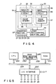
- Fig. 4 schematically shows the control circuit of laser printer 3.
- Laser printer 3 includes connectors 31 and 32, facsimile interface 35, computer interface 38, laser photographic printing unit 39 and operating section 40.
- Connector 31 is used for connection with facsimile device 1 via cable 4
- connector 32 is used for connection with personal computer 5 via cable 6.
- Facsimile interface 35 includes density converting circuit 33 connected to connector 31 and image memory 34 connected to density converting circuit 33.
- Computer interface 38 includes image converting circuit 36 connected to connector 32 and image memory 37 connected to image converting circuit 36.
- laser photographic printing unit 39 is connected to connector 32, image memories 34 and 37, and operating section 40.
- the recording control signal from facsimile device 1 is supplied to density converting circuit 33 via connector 31.
- the facsimile image density is 8 lines/mm (in a horizontal direction) x 3.85 or 7.7 lines/mm (in a vertical direction), for example.
- the printing density of the laser printer is 300 dots/inch (in a horizontal direction) x 300 dots/inch (in a vertical direction).
- Density converting circuit 33 performs density conversion process so as to convert the density of image information included in the recording control signal in conformity with the printing density of laser printer 3.
- Image memory 34 is a buffer for temporarily storing image information supplied from density converting circuit 33, and is provided to compensate for a difference between the low printing speed of laser photographic printing unit 39 and the signal receiving speed of the facsimile signal.
- Image converting circuit 36 converts character code or ASCII code supplied from computer 5 into image information.
- Image memory 37 is a buffer for temporarily storing image information supplied from image converting circuit 36, and is provided to compensate for a difference between the low printing speed of laser photographic printing unit 39 and the supplying speed of the character code.
- Laser photographic printing unit 39 reads out image information from one of image memories 34 and 37, and prints the readout image information on ordinary paper used as the recording paper. While laser printer 3 is used as an external printing device, laser photographic printing unit 39 reads out image information from image memory 34 in preference to image memory 37.
- Fig. 5 shows processor unit 25 more in detail.
- Processor unit 25 includes CPU 25a, RAM 25b, ROM 25c, I/O interface 25d and bus line 25e.
- CPU 25a, RAM 25b, ROM 25c and I/O interface 25d are connected to each other via bus line 25e.
- ROM 25c is used to store the control program for CPU 25a
- RAM 25b is used for temporarily storing input and output data of CPU 25a.
- RAM 25b includes buffer area 25bf for storing image information necessary for the printing operation of thermosensitive paper printing section 26 or laser printer 3 for ordinary paper and flag register area 25br for storing various flags including a flag for specifying one of the internal and external printers selected by operating printer selection key 15b, for example.
- I/O interface 25d is used for the data transfer between CPU 25a and each of operation section 7, FAX modem 22, telephone circuit 23, original document reader 24, thermosensitive printing section 26, switching circuit 27 and connector 28.
- Switching circuit 27 includes two-input NAND gates 41 to 46, inverter 47, and drivers 48 to 50.
- the first input terminals of NAND gates 41 to 43 are connected to receive printer selection signal P-SELECT which is supplied from processor unit 25 to select one of the internal and external printer modes, and the first input terminals of NAND gates 44 to 46 are connected to receive printer selection signal P-SELECT via inverter 47.
- the second input terminals of NAND gates 41 and 44 are each connected to receive image information as dot print data P-DATA in the serial format from processor unit 25.
- the second input terminals of NAND gates 42 and 45 are each connected to receive latch signal LATCH which is supplied from processor unit 25 to latch dot print data P-DATA of one line.
- the second input terminals of NAND gates 43 and 46 are each connected to receive synchronizing clock signal CLOCK from processor unit 25.
- Output signals of NAND gates 41 to 43 are supplied to drivers 48 to 50 which in turn supply output signals to laser printer 3 connected to connector 28.
- Output signals of NAND gates 44 to 46 are supplied to thermosensitive paper printing section 26.
- dot print data P-DATA, latch signal LATCH and synchronization clock signal CLOCK are supplied as external print data LP-DATA, external latch signal LP-LATCH and external synchronization clock signal LP-CLOCK from NAND gates 41 to 43 when the external printer is selected by printer selection signal P-SELECT, and supplied as internal print data TP-DATA, internal latch signal TP-LATCH and internal synchronization clock signal TP-CLOCK from NAND gates 44 to 46 when the internal printer is selected by printer selection signal P-SELECT.
- Processor unit 25 generates page control signal PAGE indicting the start and end of supply of print data of one page.
- Page control signal PAGE is supplied from processor unit 25 directly to laser printer 3 connected to connector 28.
- Laser printer 3 supplies busy signal LP-BUSY, error signal LP-ERROR and on-line signal LP-ONLINE as status signals to processor unit 25 via connector 28.
- Figs. 7(A) to 7(G) are timing charts of signals transmitted via connector 28.
- Page control signal PAGE is shown in Fig. 7(A).
- Laser printer 3 is set ready for input reception in response to the rise of page control signal PAGE, and terminates the input reception and starts the printing operation in response to the fall of page control signal PAGE.
- External synchronization clock signal LP-CLOCK is shown in Fig. 7(B) and external print data LP-DATA is shown in Fig. 7(C).
- External synchronization clock signal LP-CLOCK includes 1728 clock pulses as synchronization clock pulses for serial dot print data of one line indicated by each block in Fig. 7(C).
- External latch signal LP-LATCH is shown in Fig. 7(D).
- External latch signal LP-LATCH includes a pulse generated each time the transfer of serial dot print data of one line is completed.
- serial print data of one line is subjected to the density conversion process in response to each pulse in the external latch signal and then stored into image memory 34.
- Busy signal LP-BUSY is shown in Fig. 7(E).
- Busy signal LP-BUSY is set to an "H" level when, for example, no available storage area is detected in the reception buffer and laser printer 3 cannot continue to receive serial print data. If laser printer 3 is set in a condition in which data can be received, busy signal LP-BUSY is set to an "L" level as shown in Fig. 7(E).
- Error signal LP-ERROR is shown in Fig. 7(F).
- Error signal LP-ERROR is set to "H" level when, for example, an abnormal condition such as no recording paper, a jam of paper, no toner and inadequate operation temperature of the fixing device is detected and the printing operation cannot be effected. In contrast, when the printing operation can be effected, Error signal LP-ERROR is set to "L" level as shown in Fig. 7(F). On-line signal LP-ONLINE is also shown in Fig. 7(F). As shown in Fig. 7(F), on-line signal LP-ONLINE is set to "H" level when laser printer 3 is connected to connector 28 and the power source is turned on. In a case where laser printer 3 is not connected to connector 28 or the power source of laser printer 3 is turned off, on-line signal LP-ONLINE is set to "L" level.
- lamp sections D1 to D4 are activated when no recording paper, a jam of recording paper, no toner and an inadequate operation temperature of the fixing device are detected, respectively. Further, lamp section D5 is activated when the power source of laser printer 3 is turned on.
- liquid crystal display unit 16 displays a message of "EXTERNAL PRINTER NOT READY" when it is detected that busy signal LP-BUSY, error signal LP-ERROR and on-line signal LP-ONLINE are not set to "L", "L” and “H” levels, respectively.
- thermosensitive paper printing section 26 is directly supplied to processor unit 25 which in turn detects the absence of recording paper and jam of paper in thermosensitive paper printing section 26 based on the status signal.
- Figs. 8A to 8C are flow charts showing the operation of processor unit 25.
- the communication control operation is effected by reading out the control program from ROM 25c and executing the control program by means of CPU 25a.
- the control program is initiated in the flowchart shown in Fig. 8A
- the control circuit is initialized in step S1, and it is checked in steps S2 and S3 whether transmission and reception commands are received or not. When neither of the commands are received, steps S2 and S3 are repeatedly effected. If the transmission command is detected in step S2, the facsimile transmitting operation is effected in step S4.
- processor unit 25 causes original document reader 24 to read image information from the original document, causes FAX modem 22 to convert the image information into a corresponding facsimile signal, and controls network control circuit 21 so as to transmit the facsimile signal to telephone line 2.
- the receiving operation is effected in step S5.
- processor unit 25 controls network control circuit 21 so as to supply the facsimile signal from telephone line 2 to FAX modem 22, and causes FAX modem 22 to extract image information from the facsimile signal. Further, processor unit 25 performs recording control process for the image information in the facsimile receiving operation.
- Step S11 the printer flag in flag register 25br is checked in step S11. If it is detected in step S11 that the external printer mode is set, it is checked in steps S12, S13 and S14 whether the external printer or laser printer 3 can be used or not. Step S15 is effected when it is detected in steps S12, S13 and S14 that the power source of the external printer is turned on, the external printer is not in the error condition, and the external printer is not in the busy condition, respectively.
- step S15 printer select signal P-SELECT is raised and the image information is supplied as a recording control signal from processor unit 25 to laser printer 3 via switching circuit 27.
- laser printer 3 prints the image information on the ordinary paper.
- the printing operation of laser printer 3 is kept effected until the image information of one page is printed.
- step S16 it is checked in step S17 whether the last page is printed or not. If it is detected in step S17 that the last page is not printed, step S11 is effected again. In contrast, if it is detected in step S17 that the last page is printed, step S2 is effected again.
- Step S18 is effected when it is detected in one of steps S12 to S14 that the external printer cannot be used.
- step S18 a message is displayed on display unit 16 to inform that the external printer cannot be used.
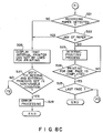
- step S19 it is checked in step S19 whether or not the internal printer or thermosensitive paper printing section 26 and the external printer are both set in the non-usable condition. If it is detected that both the printers are in the non-usable condition, an error processing for inhibiting the use of the external printer is effected in step S20 and thus the recording control process is completed.
- thermosensitive paper printing section 26 If it is detected in step S19 that neither of the internal and external printers are set in the non-usable condition, or if it is detected in step S11 that the internal printer mode is set, it is checked in steps S21 and S23 whether thermosensitive paper printing section 26 can be used or not. Step S23 is effected when the presence of recording paper is detected in step S21 and no jam of paper is detected in step S22. In step S23, printer select signal P-SELECT is lowered and image information is supplied as a recording control signal from processor unit 25 to thermosensitive paper printing section 26 via switching circuit 27. After this, printing section 26 prints the image information on thermosensitive paper. The printing operation of printing section 26 is continued until image information of one page is completely printed.
- step S24 If it is detected in step S24 that the printing operation of image information of one page is completed, it is checked in step S25 whether the printing operation of the last page is completed or not. If it is detected in step S25 that the last page is not printed, step S11 is effected again. In contrast, if it is detected in step S25 that the last page is printed, step S2 is effected again.
- Step S26 is effected when it is detected in one of steps S21 and S22 that the internal printer cannot be used.
- step S26 a message is displayed on display unit 16 to inform that the internal printer is not ready for printing.
- step S27 it is checked in step S27 whether or not the internal and external printers are both set in the non-usable condition. If it is detected that both the printers are in the non-usable condition, an error processing for inhibiting the use of the internal printer is effected in step S28 and then the recording control process is completed. In contrast, if both the printers are not set in the non-usable condition, step S12 is effected.
- thermosensitive paper in a case where it is sufficient only if image information can be printed on thermosensitive paper, it is required to purchase only facsimile device 1, and therefore it does not cost much. After this, if it becomes necessary to record the received image information on ordinary paper, it is only required to purchase laser printer 3 and connect laser printer 3 to connector 28 of facsimile device 1 via cable 4. In this way, it is possible to purchase laser printer 3 later when required, and it is economically advantageous in comparison with the case wherein two different types of facsimile devices are purchased.
- thermosensitive paper printing section 26 With laser printer 3 connected, internal thermosensitive paper printing section 26 or external laser printer 3 can be selectively used by operating printer select key 15b. Therefore, when it is required to record and store the received image information over a long period of time, laser printer 3 can be operated to record the image information on ordinary paper, and when it is not required to store the recorded image information over a long period of time, thermosensitive paper printing section 26 may be operated to record the image information on thermosensitive paper.
- the external printer connected, even if a selected one of the printers becomes defective and cannot effect the printing operation for some reason, the other printer is automatically selected to effect the printing operation. Therefore, the received image information can be reliably recorded, increasing the reliability of the facsimile device.
- laser printer 3 can be connected not only to facsimile device 1 but also to personal computer 5, laser printer 3 can be effectively used, thus further attaining the economical advantage.
- laser printer 3 is used as an external recording device, but it is not limited to this.
- heat-transfer recording type, electrostatic photographic recording type or LED photographic recording type printers can also be used.
- the external recording device is not limited to a device using normal paper but a device using a different type of paper can be used as the external recording device.
- the external recording device can be of the same type as the internal recording device using thermosensitive paper. Since the external recording device can be arranged in position different from that of the internal recording device, the versatility of the facsimile device can be further increased.
- thermosensitive paper printing device can be used as the external recording device. In this case, the same effect as that in the above embodiment can be attained.
- laser printer 3 can be replaced by a recording device using recording medium such as a magnetic floppy disk.
- a facsimile device in which the external recording device can be used in addition to the internal recording device.
- the internal and external recording devices can be selectively used, increasing the versatility and economical efficiency of the facsimile device.
Abstract
Description
- This invention relates to a communication terminal device for recording communication information.
- Facsimile devices are known as communication terminal devices for transferring image information such as characters and image patterns. In the facsimile device, image information is extracted from a received signal and recorded. In general, thermosensitive paper or ordinary paper is used as a recording medium. When ordinary paper is used as the recording medium, it becomes difficult to manufacture the facsimile device simple in construction and at a low cost. For this reason, facsimile devices for printing image information on the thermosensitive recording paper are now most commonly used.
- However, unlike the ordinary recording paper, the thermosensitive recording paper is subject to change in quality, and it has a defect that the printed image information will gradually disappear with time. Therefore, it is not preferable to keep the printed thermosensitive recording paper on a file to be stored over a long period of time. In addition, when characters are written on the thermosensitive recording paper, it is difficult to write characters with a pencil, for example, because of the smooth surface of the thermosensitive recording paper.
- When a facsimile device is purchased, the size or the price thereof is an important factor for determining the type of the facsimile device if the above defect of the thermosensitive recording paper does not cause any serious problem for actual applications of the facsimile device. Suppose now that a user has purchased a facsimile device for printing image information on thermosensitive recording paper. After this, if it becomes necessary to keep recorded image information over a long period of time, the user will have to think about purchasing a different facsimile device which can print image information on ordinary paper. If the user actually purchases the latter type of facsimile device, more expense will be imposed on the user in comparison with the case where he purchased the latter type facsimile device without purchasing the former type facsimile device at the beginning.
- An object of this invention is to provide an economical communication terminal device in which recording medium for image information can be selectively set.
- The object can be attained by a communication terminal device which comprises a communication circuit for receiving image information; an internal printing section for printing a specified recording medium; a connector section; a selecting section for selecting one of first and second modes; and a control circuit for converting the received image information into image information of the recording format, and supplying the image information of the recording format to the internal printing section and the connector section respectively in the first and second mode.
- In the communication terminal device, an external recording device which effects the recording operation with respect to recording medium other than the specified recording medium can be connected to the connector section and image information can be transferred to the external recording device via the connector section in the second mode. Thus, since image information can be recorded on recording medium other than the specified recording medium by means of the external recording device, it is not necessary to replace the communication terminal device by a different one according to change of the recording medium. The external recording device is a printing device using ordinary paper as the recording medium, a magnetic disk drive device using a magnetic disk as the recording medium or the like.
- This invention can be more fully understood from the following detailed description when taken in conjunction with the accompanying drawings, in which:
- Fig. 1 is a perspective view showing a facsimile device according to one embodiment of this invention;
- Fig. 2 shows an operating section of the facsimile device shown in Fig. 1;
- Fig. 3 is a block diagram showing a control circuit of the facsimile device shown in Fig. 1;
- Fig. 4 is a block diagram showing the circuit of a laser printer connected to the facsimile device shown in Fig. 1;
- Fig. 5 shows in detail the construction of a processor unit shown in Fig. 3;
- Fig. 6 shows in detail the construction of a switching circuit shown in Fig. 3;
- Figs. 7A to 7G are timing charts of signals transmitted via a connector shown in Fig. 3; and
- Figs. 8A to 8C are flowcharts showing the operation of the processor unit shown in Fig. 3.
- There will now be described a facsimile device according to one embodiment of this invention with reference to Figs. 1 to 8C. Fig. 1 shows the external appearance of
facsimile device 1.Facsimile device 1 is connected totelephone line 2 and to an external recording device, for example,laser printer 3 viacable 4.Laser printer 3 is also connected topersonal computer 5 viacable 6. -
Facsimile device 1 includesoperating section 7, original document discharging port 8, handset 9, originaldocument inlet guide 10, original document inlet port 11 and recordedpaper discharging port 12.Operating section 7 and original document discharging port 8 are provided on the upper surface of a casing, and handset 9 is mounted on the side portion of the casing. Originaldocument inlet guide 10 and original document inlet port 11 are provided on the rear side of the casing, and recordedpaper discharging port 12 is provided in the front surface of the casing. - Fig. 2 shows
operating section 7 offacsimile device 1.Operating section 7 includes pushtype telephone keys 13, one-touch dial keys 14, facsimile keys and liquidcrystal display unit 16. Facsimilekeys 15 include line selection key 15a for selecting one of "automatic" circuit connection and "manual" circuit connection,printer selection key 15b for selecting one of internal and external printer modes, resolution selection key 15c for selecting one of normal image quality and fine image quality,transmission start key 15d andtransmission stop key 15e. - Fig. 3 schematically shows a control circuit of
facsimile device 1. The control circuit offacsimile device 1 includesnetwork control circuit 21,FAX modem 22,telephone circuit 23,original document reader 24,processor unit 25, thermosensitivepaper printing section 26,switching circuit 27 andconnector 28.Telephone line 2 is connectednetwork control circuit 21 and handset 9 is connected totelephone circuit 23. Further,network control circuit 21 is connected totelephone circuit 23 andFAX modem 22.Processor unit 25 is connected tooperating section 7,network control circuit 21,FAX modem 22,telephone circuit 23,original document reader 24, thermosensitivepaper printing section 26,switching circuit 27 andconnector 28.Switching circuit 27 is connected to thermosensitivepaper printing section 26 andconnector 28. Thermosensitivepaper printing section 26 is used as the internal recording device offacsimile device 1, andconnector 28 is used to connectfacsimile device 1 tolaser printer 3 viacord 4.Original document reader 24 is used to read image information from the original document inserted into original document inserting port 11.FAX modem 22 is a communication control interface for the facsimile communication, andtelephone circuit 23 is a communication control interface for the speech communication.Network control circuit 21 is used to selectively connect one oftelephone circuit 23 andFAX modem 22 totelephone line 2, and the operation thereof is controlled byprocessor unit 25. That is,telephone circuit 23 is connected totelephone line 2 when the speech communication is effected by means of handset 9, andFAX modem 22 is connected totelephone line 2 when the facsimile communication is effected. - In the facsimile transmission, image information is supplied from
original document reader 24 toFAX modem 22 viaprocessor unit 25. The image information is converted into the format of facsimile signal inFAX modem 22, and then transmitted totelephone line 2 vianetwork control circuit 21. In the facsimile reception, a facsimile signal is supplied toFAX modem 22 fromtelephone line 2 vianetwork control circuit 21.FAX modem 22 extracts image information from the received facsimile signal and supplies the same toprocessor unit 25. In theprocessor unit 25, the image information is converted into a recording control signal. The recording control signal is supplied to one of thermosensitivepaper printing section 26 andconnector 28 viaswitching circuit 27. At this time, the operation ofswitching circuit 27 is controlled byprocessor unit 25. For example, when the internal printer is specified byprinter selection key 15b,switching circuit 27 is set to permit the recording control signal to be supplied to thermosensitivepaper printing section 26. In contrast, when the external printer is specified by printer selection key 15a,switching circuit 27 is set to permit the recording control signal to be supplied toconnector 28. Further, the status signal oflaser printer 3 is supplied toprocessor unit 25 viaconnector 28. If it is detected from the status signal thatlaser printer 3 is not ready for printing,switching circuit 27 causes the recording control signal to be supplied to thermosensitivepaper printing section 26. - When the recording control signal is supplied to thermosensitive
paper printing section 26, thermosensitivepaper printing section 26 prints the image information on thermosensitive paper used as the recording medium. - Fig. 4 schematically shows the control circuit of
laser printer 3.Laser printer 3 includesconnectors facsimile interface 35,computer interface 38, laserphotographic printing unit 39 and operating section 40.Connector 31 is used for connection withfacsimile device 1 viacable 4, andconnector 32 is used for connection withpersonal computer 5 viacable 6.Facsimile interface 35 includesdensity converting circuit 33 connected toconnector 31 andimage memory 34 connected todensity converting circuit 33.Computer interface 38 includesimage converting circuit 36 connected toconnector 32 andimage memory 37 connected to image convertingcircuit 36. Further, laserphotographic printing unit 39 is connected toconnector 32,image memories - The recording control signal from
facsimile device 1 is supplied todensity converting circuit 33 viaconnector 31. In general, the facsimile image density is 8 lines/mm (in a horizontal direction) x 3.85 or 7.7 lines/mm (in a vertical direction), for example. In contrast, the printing density of the laser printer is 300 dots/inch (in a horizontal direction) x 300 dots/inch (in a vertical direction).Density converting circuit 33 performs density conversion process so as to convert the density of image information included in the recording control signal in conformity with the printing density oflaser printer 3.Image memory 34 is a buffer for temporarily storing image information supplied fromdensity converting circuit 33, and is provided to compensate for a difference between the low printing speed of laserphotographic printing unit 39 and the signal receiving speed of the facsimile signal.Image converting circuit 36 converts character code or ASCII code supplied fromcomputer 5 into image information.Image memory 37 is a buffer for temporarily storing image information supplied fromimage converting circuit 36, and is provided to compensate for a difference between the low printing speed of laserphotographic printing unit 39 and the supplying speed of the character code. - Laser
photographic printing unit 39 reads out image information from one ofimage memories laser printer 3 is used as an external printing device, laserphotographic printing unit 39 reads out image information fromimage memory 34 in preference to imagememory 37. - Fig. 5 shows
processor unit 25 more in detail.Processor unit 25 includesCPU 25a,RAM 25b, ROM 25c, I/O interface 25d andbus line 25e.CPU 25a,RAM 25b, ROM 25c and I/O interface 25d are connected to each other viabus line 25e. ROM 25c is used to store the control program forCPU 25a, andRAM 25b is used for temporarily storing input and output data ofCPU 25a.RAM 25b includes buffer area 25bf for storing image information necessary for the printing operation of thermosensitivepaper printing section 26 orlaser printer 3 for ordinary paper and flag register area 25br for storing various flags including a flag for specifying one of the internal and external printers selected by operating printer selection key 15b, for example. I/O interface 25d is used for the data transfer betweenCPU 25a and each ofoperation section 7,FAX modem 22,telephone circuit 23,original document reader 24,thermosensitive printing section 26, switchingcircuit 27 andconnector 28. - Fig. 6 shows the construction of switching
circuit 27 in more detail.Switching circuit 27 includes two-input NAND gates 41 to 46,inverter 47, anddrivers 48 to 50. The first input terminals ofNAND gates 41 to 43 are connected to receive printer selection signal P-SELECT which is supplied fromprocessor unit 25 to select one of the internal and external printer modes, and the first input terminals ofNAND gates 44 to 46 are connected to receive printer selection signal P-SELECT viainverter 47. The second input terminals ofNAND gates processor unit 25. The second input terminals ofNAND gates processor unit 25 to latch dot print data P-DATA of one line. The second input terminals ofNAND gates processor unit 25. Output signals ofNAND gates 41 to 43 are supplied todrivers 48 to 50 which in turn supply output signals tolaser printer 3 connected toconnector 28. Output signals ofNAND gates 44 to 46 are supplied to thermosensitivepaper printing section 26. That is, dot print data P-DATA, latch signal LATCH and synchronization clock signal CLOCK are supplied as external print data LP-DATA, external latch signal LP-LATCH and external synchronization clock signal LP-CLOCK fromNAND gates 41 to 43 when the external printer is selected by printer selection signal P-SELECT, and supplied as internal print data TP-DATA, internal latch signal TP-LATCH and internal synchronization clock signal TP-CLOCK fromNAND gates 44 to 46 when the internal printer is selected by printer selection signal P-SELECT. -
Processor unit 25 generates page control signal PAGE indicting the start and end of supply of print data of one page. Page control signal PAGE is supplied fromprocessor unit 25 directly tolaser printer 3 connected toconnector 28.Laser printer 3 supplies busy signal LP-BUSY, error signal LP-ERROR and on-line signal LP-ONLINE as status signals toprocessor unit 25 viaconnector 28. - Figs. 7(A) to 7(G) are timing charts of signals transmitted via
connector 28. Page control signal PAGE is shown in Fig. 7(A).Laser printer 3 is set ready for input reception in response to the rise of page control signal PAGE, and terminates the input reception and starts the printing operation in response to the fall of page control signal PAGE. External synchronization clock signal LP-CLOCK is shown in Fig. 7(B) and external print data LP-DATA is shown in Fig. 7(C). External synchronization clock signal LP-CLOCK includes 1728 clock pulses as synchronization clock pulses for serial dot print data of one line indicated by each block in Fig. 7(C). External latch signal LP-LATCH is shown in Fig. 7(D). External latch signal LP-LATCH includes a pulse generated each time the transfer of serial dot print data of one line is completed. Inlaser printer 3, serial print data of one line is subjected to the density conversion process in response to each pulse in the external latch signal and then stored intoimage memory 34. Busy signal LP-BUSY is shown in Fig. 7(E). Busy signal LP-BUSY is set to an "H" level when, for example, no available storage area is detected in the reception buffer andlaser printer 3 cannot continue to receive serial print data. Iflaser printer 3 is set in a condition in which data can be received, busy signal LP-BUSY is set to an "L" level as shown in Fig. 7(E). Error signal LP-ERROR is shown in Fig. 7(F). Error signal LP-ERROR is set to "H" level when, for example, an abnormal condition such as no recording paper, a jam of paper, no toner and inadequate operation temperature of the fixing device is detected and the printing operation cannot be effected. In contrast, when the printing operation can be effected, Error signal LP-ERROR is set to "L" level as shown in Fig. 7(F). On-line signal LP-ONLINE is also shown in Fig. 7(F). As shown in Fig. 7(F), on-line signal LP-ONLINE is set to "H" level whenlaser printer 3 is connected toconnector 28 and the power source is turned on. In a case wherelaser printer 3 is not connected toconnector 28 or the power source oflaser printer 3 is turned off, on-line signal LP-ONLINE is set to "L" level. - In operating section SP of
laser printer 3, lamp sections D1 to D4 are activated when no recording paper, a jam of recording paper, no toner and an inadequate operation temperature of the fixing device are detected, respectively. Further, lamp section D5 is activated when the power source oflaser printer 3 is turned on. - In
operating section 7 offacsimile device 1, liquidcrystal display unit 16 displays a message of "EXTERNAL PRINTER NOT READY" when it is detected that busy signal LP-BUSY, error signal LP-ERROR and on-line signal LP-ONLINE are not set to "L", "L" and "H" levels, respectively. - Like the status signal of
laser printer 3, the status signal of thermosensitivepaper printing section 26 is directly supplied toprocessor unit 25 which in turn detects the absence of recording paper and jam of paper in thermosensitivepaper printing section 26 based on the status signal. - Now, the control operation of the facsimile communication is explained with reference to Figs. 8A to 8C. Figs. 8A to 8C are flow charts showing the operation of
processor unit 25. The communication control operation is effected by reading out the control program from ROM 25c and executing the control program by means ofCPU 25a. When the control program is initiated in the flowchart shown in Fig. 8A, the control circuit is initialized in step S1, and it is checked in steps S2 and S3 whether transmission and reception commands are received or not. When neither of the commands are received, steps S2 and S3 are repeatedly effected. If the transmission command is detected in step S2, the facsimile transmitting operation is effected in step S4. In the facsimile transmitting operation,processor unit 25 causesoriginal document reader 24 to read image information from the original document, causesFAX modem 22 to convert the image information into a corresponding facsimile signal, and controlsnetwork control circuit 21 so as to transmit the facsimile signal totelephone line 2. When it is detected in step S3 that the reception command is received, the receiving operation is effected in step S5. In the facsimile receiving operation,processor unit 25 controlsnetwork control circuit 21 so as to supply the facsimile signal fromtelephone line 2 to FAXmodem 22, and causesFAX modem 22 to extract image information from the facsimile signal. Further,processor unit 25 performs recording control process for the image information in the facsimile receiving operation. - The flowchart of the recording control process is shown in Figs. 8B and 8C. In the recording control process, the printer flag in flag register 25br is checked in step S11. If it is detected in step S11 that the external printer mode is set, it is checked in steps S12, S13 and S14 whether the external printer or
laser printer 3 can be used or not. Step S15 is effected when it is detected in steps S12, S13 and S14 that the power source of the external printer is turned on, the external printer is not in the error condition, and the external printer is not in the busy condition, respectively. In step S15, printer select signal P-SELECT is raised and the image information is supplied as a recording control signal fromprocessor unit 25 tolaser printer 3 via switchingcircuit 27. After this,laser printer 3 prints the image information on the ordinary paper. The printing operation oflaser printer 3 is kept effected until the image information of one page is printed. When it is detected in step S16 that the printing operation of the image information of one page is completed, it is checked in step S17 whether the last page is printed or not. If it is detected in step S17 that the last page is not printed, step S11 is effected again. In contrast, if it is detected in step S17 that the last page is printed, step S2 is effected again. - Step S18 is effected when it is detected in one of steps S12 to S14 that the external printer cannot be used. In step S18, a message is displayed on
display unit 16 to inform that the external printer cannot be used. After this, it is checked in step S19 whether or not the internal printer or thermosensitivepaper printing section 26 and the external printer are both set in the non-usable condition. If it is detected that both the printers are in the non-usable condition, an error processing for inhibiting the use of the external printer is effected in step S20 and thus the recording control process is completed. - If it is detected in step S19 that neither of the internal and external printers are set in the non-usable condition, or if it is detected in step S11 that the internal printer mode is set, it is checked in steps S21 and S23 whether thermosensitive
paper printing section 26 can be used or not. Step S23 is effected when the presence of recording paper is detected in step S21 and no jam of paper is detected in step S22. In step S23, printer select signal P-SELECT is lowered and image information is supplied as a recording control signal fromprocessor unit 25 to thermosensitivepaper printing section 26 via switchingcircuit 27. After this, printingsection 26 prints the image information on thermosensitive paper. The printing operation ofprinting section 26 is continued until image information of one page is completely printed. If it is detected in step S24 that the printing operation of image information of one page is completed, it is checked in step S25 whether the printing operation of the last page is completed or not. If it is detected in step S25 that the last page is not printed, step S11 is effected again. In contrast, if it is detected in step S25 that the last page is printed, step S2 is effected again. - Step S26 is effected when it is detected in one of steps S21 and S22 that the internal printer cannot be used. In step S26, a message is displayed on
display unit 16 to inform that the internal printer is not ready for printing. After this, it is checked in step S27 whether or not the internal and external printers are both set in the non-usable condition. If it is detected that both the printers are in the non-usable condition, an error processing for inhibiting the use of the internal printer is effected in step S28 and then the recording control process is completed. In contrast, if both the printers are not set in the non-usable condition, step S12 is effected. - In the above embodiment of this invention, in a case where it is sufficient only if image information can be printed on thermosensitive paper, it is required to purchase
only facsimile device 1, and therefore it does not cost much. After this, if it becomes necessary to record the received image information on ordinary paper, it is only required to purchaselaser printer 3 and connectlaser printer 3 toconnector 28 offacsimile device 1 viacable 4. In this way, it is possible to purchaselaser printer 3 later when required, and it is economically advantageous in comparison with the case wherein two different types of facsimile devices are purchased. - With
laser printer 3 connected, internal thermosensitivepaper printing section 26 orexternal laser printer 3 can be selectively used by operating printer select key 15b. Therefore, when it is required to record and store the received image information over a long period of time,laser printer 3 can be operated to record the image information on ordinary paper, and when it is not required to store the recorded image information over a long period of time, thermosensitivepaper printing section 26 may be operated to record the image information on thermosensitive paper. - In this way, it is possible to selectively record the received image information on normal paper or thermosensitive paper as required, and the versatility of
facsimile device 1 can be increased. - Further, with the external printer connected, even if a selected one of the printers becomes defective and cannot effect the printing operation for some reason, the other printer is automatically selected to effect the printing operation. Therefore, the received image information can be reliably recorded, increasing the reliability of the facsimile device.
- Since
laser printer 3 can be connected not only tofacsimile device 1 but also topersonal computer 5,laser printer 3 can be effectively used, thus further attaining the economical advantage. - In the above embodiment,
laser printer 3 is used as an external recording device, but it is not limited to this. For example, heat-transfer recording type, electrostatic photographic recording type or LED photographic recording type printers can also be used. - Further, the external recording device is not limited to a device using normal paper but a device using a different type of paper can be used as the external recording device. In this case, the external recording device can be of the same type as the internal recording device using thermosensitive paper. Since the external recording device can be arranged in position different from that of the internal recording device, the versatility of the facsimile device can be further increased.
- If the internal recording device provided in the facsimile device is a device using normal paper, a thermosensitive paper printing device can be used as the external recording device. In this case, the same effect as that in the above embodiment can be attained.
- Further,
laser printer 3 can be replaced by a recording device using recording medium such as a magnetic floppy disk. - As described above, according to this invention, there is provided a facsimile device in which the external recording device can be used in addition to the internal recording device. Thus, the internal and external recording devices can be selectively used, increasing the versatility and economical efficiency of the facsimile device.
Claims (11)
a communication circuit (21, 22) for receiving image information;
an internal recording device for effecting the printing operation with respect to a specified recording medium; and
control means for converting the received image information into a recording format and causing said internal recording device to record the converted image information;
characterized by further comprising a connector section (28); and selection means (7) for selectively setting one of the internal and external recording modes and characterized in that said control means (25, 27) supplies the converted image information to said internal recording device (26) and said connector section (28) respectively in the internal and external recording modes.
a communication circuit (21, 22) for receiving image information;
an internal printing device for printing image information on a thermosensitive paper; and
control means for converting the received image information into a recording format and causing said internal printing device to print the converted image information;
characterized by further comprising a connector section (28); and selection means (7) for selectively setting one of the internal and external recording modes and characterized in that said control means (25, 27) supplies the converted image information to said internal printing device (26) and said connector section (28) respectively in the internal and external recording modes.
Applications Claiming Priority (2)
| Application Number | Priority Date | Filing Date | Title |
|---|---|---|---|
| JP263144/87 | 1987-10-19 | ||
| JP62263144A JPH01106559A (en) | 1987-10-19 | 1987-10-19 | Facsimile equipment |
Publications (2)
| Publication Number | Publication Date |
|---|---|
| EP0312894A2 true EP0312894A2 (en) | 1989-04-26 |
| EP0312894A3 EP0312894A3 (en) | 1991-06-12 |
Family
ID=17385418
Family Applications (1)
| Application Number | Title | Priority Date | Filing Date |
|---|---|---|---|
| EP19880116868 Withdrawn EP0312894A3 (en) | 1987-10-19 | 1988-10-11 | Communication terminal device |
Country Status (4)
| Country | Link |
|---|---|
| US (1) | US4930017A (en) |
| EP (1) | EP0312894A3 (en) |
| JP (1) | JPH01106559A (en) |
| KR (1) | KR920005193B1 (en) |
Cited By (5)
| Publication number | Priority date | Publication date | Assignee | Title |
|---|---|---|---|---|
| FR2641927A1 (en) * | 1989-01-19 | 1990-07-20 | Murata Machinery Ltd | Device for recording in a fax apparatus |
| EP0440099A2 (en) * | 1990-01-30 | 1991-08-07 | Teletron Ltd. | Message receiving apparatus |
| EP0675632A2 (en) * | 1994-03-30 | 1995-10-04 | Canon Kabushiki Kaisha | Image recording apparatus and method therefor |
| AU694061B2 (en) * | 1995-10-16 | 1998-07-09 | Fuji Xerox Co., Ltd. | Facsimile apparatus |
| FR2762543A1 (en) * | 1997-04-28 | 1998-10-30 | Investix Sa | PRINTER FOR VOICE SERVER TYPE INFORMATION TRANSFER SYSTEM AND VOICE SERVER SYSTEM COMPRISING SUCH PRINTERS |
Families Citing this family (24)
| Publication number | Priority date | Publication date | Assignee | Title |
|---|---|---|---|---|
| JP2801200B2 (en) * | 1988-05-11 | 1998-09-21 | キヤノン株式会社 | Data communication device |
| JPH0349357A (en) * | 1989-07-18 | 1991-03-04 | Canon Inc | Facsimile equipment |
| JP2962513B2 (en) * | 1989-11-13 | 1999-10-12 | 株式会社リコー | Group 3 facsimile machine |
| US5072303A (en) * | 1989-12-29 | 1991-12-10 | Morton Silverberg | Combined printer and facsimile apparatus which scans using different scan rates and dot sizes |
| WO1991015818A1 (en) * | 1990-04-09 | 1991-10-17 | Richard Kollin | System for searching and retrieving data from data bases via audio access with automatic faxing of results |
| US6225983B1 (en) * | 1990-10-11 | 2001-05-01 | Fuji Xerox Co., Ltd | Operation key registration system for a coordinate input device |
| US5845144A (en) * | 1991-12-25 | 1998-12-01 | Canon Kabushiki Kaisha | Information processing apparatus with internal printer |
| JP3133806B2 (en) * | 1992-01-14 | 2001-02-13 | キヤノン株式会社 | Function expansion device for ultra-small facsimile machine |
| JP3195398B2 (en) * | 1992-02-05 | 2001-08-06 | キヤノン株式会社 | Facsimile apparatus and control method thereof |
| JPH06188937A (en) | 1992-12-16 | 1994-07-08 | Canon Inc | Data processor |
| JP3581389B2 (en) * | 1993-02-23 | 2004-10-27 | キヤノン株式会社 | Image communication method and apparatus |
| JPH07123194A (en) * | 1993-10-27 | 1995-05-12 | Nec Corp | Facsimile equipment with character data transmission reception function |
| KR0136118B1 (en) | 1994-01-21 | 1998-04-27 | 김광호 | Circuit and method for transmitting and receiving data using electrophotographic method |
| JP3296920B2 (en) * | 1994-03-15 | 2002-07-02 | 京セラミタ株式会社 | Facsimile machine |
| US6323962B1 (en) | 1994-05-30 | 2001-11-27 | Brother Kogyo Kabushiki Kaisha | Facsimile machine with facsimile data receiver and external computer |
| US5726769A (en) | 1994-11-14 | 1998-03-10 | Canon Kabushiki Kaisha | Image processing apparatus capable of connecting external information processing terminal, and including printer unit and data processing unit |
| EP0724362B1 (en) * | 1995-01-30 | 2000-03-22 | International Business Machines Corporation | Priority controlled transmission of multimedia streams via a telecommunication line |
| US5848135A (en) * | 1995-08-01 | 1998-12-08 | In A Pinch Inc. | Battery-powered adapter |
| JP3353220B2 (en) * | 1996-03-25 | 2002-12-03 | ミノルタ株式会社 | Image processing device |
| EP0866599B1 (en) * | 1997-03-21 | 2003-02-19 | Matsushita Electric Industrial Co., Ltd. | Communication apparatus and communication control method |
| US6711637B2 (en) * | 2000-01-11 | 2004-03-23 | Canon Kabushiki Kaisha | Communication apparatus, image processing apparatus, communication system, communication method, image processing method and storage medium |
| US7180638B1 (en) | 2000-02-16 | 2007-02-20 | Ricoh Co., Ltd. | Network fax machine using a web page as a user interface |
| JP2008109231A (en) * | 2006-10-23 | 2008-05-08 | Canon Inc | Data communication system, data processor, facsimile machine, data processing method, and program |
| EP3281167A4 (en) * | 2015-04-08 | 2018-10-31 | Adi Analytics Ltd. | Qualitatively planning, measuring, making effecient and capitalizing on marketing strategy |
Citations (4)
| Publication number | Priority date | Publication date | Assignee | Title |
|---|---|---|---|---|
| US4110794A (en) * | 1977-02-03 | 1978-08-29 | Static Systems Corporation | Electronic typewriter using a solid state display to print |
| DE3438081A1 (en) * | 1983-10-17 | 1985-05-02 | Canon K.K., Tokio/Tokyo | Image-processing system |
| JPS62225064A (en) * | 1986-03-27 | 1987-10-03 | Toshiba Corp | Facsimile equipment |
| US4702630A (en) * | 1985-06-26 | 1987-10-27 | Brother Kogyo Kabushiki Kaisha | Facsimile-printer apparatus |
Family Cites Families (4)
| Publication number | Priority date | Publication date | Assignee | Title |
|---|---|---|---|---|
| US4527885A (en) * | 1981-07-15 | 1985-07-09 | Canon Kabushiki Kaisha | Image recording system having multiple image recording means |
| US4658299A (en) * | 1983-10-12 | 1987-04-14 | Canon Kabushiki Kaisha | Image processing system |
| JPS60132456A (en) * | 1983-12-21 | 1985-07-15 | Toshiba Corp | Picture processor |
| JPS62261275A (en) * | 1986-05-08 | 1987-11-13 | Tokyo Electric Co Ltd | Facsimile equipment |
-
1987
- 1987-10-19 JP JP62263144A patent/JPH01106559A/en active Pending
-
1988
- 1988-10-11 EP EP19880116868 patent/EP0312894A3/en not_active Withdrawn
- 1988-10-11 US US07/256,767 patent/US4930017A/en not_active Expired - Fee Related
- 1988-10-17 KR KR1019880013536A patent/KR920005193B1/en not_active IP Right Cessation
Patent Citations (4)
| Publication number | Priority date | Publication date | Assignee | Title |
|---|---|---|---|---|
| US4110794A (en) * | 1977-02-03 | 1978-08-29 | Static Systems Corporation | Electronic typewriter using a solid state display to print |
| DE3438081A1 (en) * | 1983-10-17 | 1985-05-02 | Canon K.K., Tokio/Tokyo | Image-processing system |
| US4702630A (en) * | 1985-06-26 | 1987-10-27 | Brother Kogyo Kabushiki Kaisha | Facsimile-printer apparatus |
| JPS62225064A (en) * | 1986-03-27 | 1987-10-03 | Toshiba Corp | Facsimile equipment |
Non-Patent Citations (1)
| Title |
|---|
| PATENT ABSTRACTS OF JAPAN vol. 12, no. 94 (E-593) 03 October 1987, & JP-A-62 225064 (TOSHIBA) 27 March 1986, * |
Cited By (10)
| Publication number | Priority date | Publication date | Assignee | Title |
|---|---|---|---|---|
| FR2641927A1 (en) * | 1989-01-19 | 1990-07-20 | Murata Machinery Ltd | Device for recording in a fax apparatus |
| EP0440099A2 (en) * | 1990-01-30 | 1991-08-07 | Teletron Ltd. | Message receiving apparatus |
| EP0440099A3 (en) * | 1990-01-30 | 1993-09-15 | Teletron Ltd. | Message receiving apparatus |
| EP0675632A2 (en) * | 1994-03-30 | 1995-10-04 | Canon Kabushiki Kaisha | Image recording apparatus and method therefor |
| EP0675632A3 (en) * | 1994-03-30 | 1995-11-02 | Canon Kk | |
| US6426805B1 (en) | 1994-03-30 | 2002-07-30 | Canon Kabushiki Kaisha | Image recording apparatus and method therefor |
| AU694061B2 (en) * | 1995-10-16 | 1998-07-09 | Fuji Xerox Co., Ltd. | Facsimile apparatus |
| US5923442A (en) * | 1995-10-16 | 1999-07-13 | Fuji Xerox Co., Ltd. | Facsimile which controls received data destination and stores or prints the data if the destination is unavailable |
| FR2762543A1 (en) * | 1997-04-28 | 1998-10-30 | Investix Sa | PRINTER FOR VOICE SERVER TYPE INFORMATION TRANSFER SYSTEM AND VOICE SERVER SYSTEM COMPRISING SUCH PRINTERS |
| WO1998049823A1 (en) * | 1997-04-28 | 1998-11-05 | Investix S.A. | Printer for data transfer system with voice server and voice server system comprising such printers |
Also Published As
| Publication number | Publication date |
|---|---|
| KR920005193B1 (en) | 1992-06-29 |
| KR890007555A (en) | 1989-06-20 |
| EP0312894A3 (en) | 1991-06-12 |
| US4930017A (en) | 1990-05-29 |
| JPH01106559A (en) | 1989-04-24 |
Similar Documents
| Publication | Publication Date | Title |
|---|---|---|
| US4930017A (en) | Communication terminal device | |
| US7187466B2 (en) | Image communication apparatus capable of reproducing data from a data processing apparatus | |
| KR100667119B1 (en) | Printing apparatus, control method therefor, and storage medium | |
| EP1300753A4 (en) | Image outputting device from mobile storage medium | |
| US4823192A (en) | Reproduction apparatus | |
| EP0554878B1 (en) | Output apparatus having automatic selection of data reception means | |
| EP0656721B1 (en) | Facsimile apparatus | |
| JP3078260B2 (en) | Reading system, control method therefor, and storage medium | |
| JPH021418B2 (en) | ||
| JP2003319111A (en) | Printer with communication function | |
| JP2567628B2 (en) | Fax machine | |
| KR100484126B1 (en) | How to upload received fax data to hard disk and print | |
| JP3126226B2 (en) | Communications system | |
| JP2521268Y2 (en) | Fax machine | |
| JP3387864B2 (en) | Reading system, control method thereof, and storage medium | |
| JPH01189277A (en) | Digital copying machine | |
| JP2004246684A (en) | Device for recording data, method and program for controlling it | |
| JP4612822B2 (en) | Image supply device, method for controlling the device, and printing system | |
| JPH077599A (en) | Device used both as laser printer and common paper facsimile, and controlling method thereof | |
| JPH02219357A (en) | Facsimile equipment | |
| JPH11321028A (en) | Image printer apparatus | |
| JPS6211544B2 (en) | ||
| JPH09247339A (en) | Image processor | |
| JPH0311144B2 (en) | ||
| JPH08265547A (en) | Image communication device |
Legal Events
| Date | Code | Title | Description |
|---|---|---|---|
| PUAI | Public reference made under article 153(3) epc to a published international application that has entered the european phase |
Free format text: ORIGINAL CODE: 0009012 |
|
| 17P | Request for examination filed |
Effective date: 19881011 |
|
| AK | Designated contracting states |
Kind code of ref document: A2 Designated state(s): DE GB SE |
|
| PUAL | Search report despatched |
Free format text: ORIGINAL CODE: 0009013 |
|
| AK | Designated contracting states |
Kind code of ref document: A3 Designated state(s): DE GB SE |
|
| 17Q | First examination report despatched |
Effective date: 19930507 |
|
| STAA | Information on the status of an ep patent application or granted ep patent |
Free format text: STATUS: THE APPLICATION IS DEEMED TO BE WITHDRAWN |
|
| 18D | Application deemed to be withdrawn |
Effective date: 19930918 |