EP0313028A2 - Arc discharge lamp with electrodeless ultraviolet radiation starting source - Google Patents
Arc discharge lamp with electrodeless ultraviolet radiation starting source Download PDFInfo
- Publication number
- EP0313028A2 EP0313028A2 EP88117416A EP88117416A EP0313028A2 EP 0313028 A2 EP0313028 A2 EP 0313028A2 EP 88117416 A EP88117416 A EP 88117416A EP 88117416 A EP88117416 A EP 88117416A EP 0313028 A2 EP0313028 A2 EP 0313028A2
- Authority
- EP
- European Patent Office
- Prior art keywords
- envelope
- ultraviolet light
- source
- arc tube
- light source
- Prior art date
- Legal status (The legal status is an assumption and is not a legal conclusion. Google has not performed a legal analysis and makes no representation as to the accuracy of the status listed.)
- Granted
Links
Images

Classifications
-
- H—ELECTRICITY
- H01—ELECTRIC ELEMENTS
- H01J—ELECTRIC DISCHARGE TUBES OR DISCHARGE LAMPS
- H01J61/00—Gas-discharge or vapour-discharge lamps
- H01J61/02—Details
- H01J61/54—Igniting arrangements, e.g. promoting ionisation for starting
-
- H—ELECTRICITY
- H01—ELECTRIC ELEMENTS
- H01J—ELECTRIC DISCHARGE TUBES OR DISCHARGE LAMPS
- H01J65/00—Lamps without any electrode inside the vessel; Lamps with at least one main electrode outside the vessel
- H01J65/04—Lamps in which a gas filling is excited to luminesce by an external electromagnetic field or by external corpuscular radiation, e.g. for indicating plasma display panels
Definitions
- This invention relates to the starting of high pressure metal vapor arc discharge lamps and is especially useful with such lamps having a metallic halide fill.
- High-pressure metal halide arc discharge lamps generally comprise an elongated arc tube containing an ionizable fill and having press seals at each end of the tube. Disposed within the arc tube are two main electrodes, one at each end. The electrodes are generally supported in the press seals and are usually connected to a thin molybdenum ribbon, disposed within the press seal, the purpose of the ribbon being to provide an electrical feedthrough of low thermal expansion, owing to its thinness, while having sufficient current carrying capacity, owing to its width.
- a starter electrode may be disposed in the arc tube, adjacent to one of the main electrodes.
- Such an electrode is used because a discharge can be ignited between the starter electrode and its adjacent electrode at a much lower starting voltage than is required to ignite a discharge between the two main electrodes. Once the discharge is ignited, the ionized gas provides primary electrons between the two main electrodes and if enough potential is available between the main electrodes a discharge will be formed therebetween.
- the starter electrode normally has a resistor in series with it to limit the current flowing through the starter electrode after the discharge has started.
- the press sealed electrical feedthrough for the starting electrode suffers a sodium electrolysis failure mechanism which leads to premature seal failure and this is made worse at the elevated seal temperatures associated with the newer low color temperature, high efficiency metal halide lamps.
- the starter electrode approach has been abandoned in favor of a high voltage starting pulse applied directly to the main electrodes of the arc tube. With this method the seal failure problems associated with the starting electrode have been overcome, however, there is a substantial statistical starting time between the time the high voltage is applied to the lamp electrodes and the gas breakdown time when the discharge occurs.
- statistical starting time it is meant that the breakdown or starting time for a given lamp and starting circuit is distributed over a range of values, such that, if the voltage is applied N times, the time at which breakdown occurs is distributed over a relatively wide range indicating that in some specific cases, the starting time is relatively short and in some cases, relatively long.
- a metal halide arc discharge lamp comprising an arc tube containing a chemical fill including mercury and metal halides and having first and second electrodes respectively sealed at opposite ends thereof.
- An outer envelope surrounds the arc tube and has first and second terminals for electrical connection thereto.
- the lamp further includes means for electrically coupling each of the electrodes of the arc tube to a respective terminal.
- An electrodeless source of ultraviolet radiation is provided within the outer envelope proximate the arc tube for producing radiation which illuminates the path between the electrodes of the arc tube to decrease the amount of time for generating a gaseous discharge therebetween.
- the source of ultraviolet radiation comprises an envelope of ultraviolet light transmitting material having opposing ends and containing a fill material.
- One of the opposing ends of the envelope of the source of ultraviolet radiation is capacitively coupled to the means for electrically coupling the first electrode of the arc tube to the first terminal.
- the other of the opposing ends of the envelope of the source of ultraviolet radiation is capacitively coupled to the means for electrically coupling the second electrode of the arc tube to the second terminal such that the source of ultraviolet radiation produces the ultraviolet radiation during lamp starting when the first and second terminals of the lamp are energized.
- the envelope of the ultraviolet light source is quartz, Vycor or ultraviolet light transmitting borosilicate glass, having a transmission band extending to a short wave limit of 253.7 nanometers or less.
- the metal halide arc discharge lamp further includes a first contact means coupling the external surface of one of the opposing ends of the envelope of the ultraviolet light source to the means for electrically coupling the first electrode of the arc tube to the first terminal.
- the lamp further includes a second contact means coupling the external surface of the other of the opposing ends of the envelope of the ultraviolet light source to the means for electrically coupling the second electrode of the arc tube to the second terminal.
- the first and second contact means each comprise a wire helically wrapped around the external surface of a respective opposing end.
- the first and second contacts each comprise a mesh sleeve made of a conductive material.
- the envelope of the ultraviolet light source contains a predetermined amount (e.g., 0.9 microcurie) of a radioactive substance such as americium 241.
- FIG. 1 illustrates a metal halide arc discharge lamp 3 which includes an evacuated outer envelope 7.
- Evacuated outer envelope 7 is hermetically sealed to a glass stem member 9.
- the shape of outer envelope 7 and the particular type of external base 11 used for the lamp may differ from that shown in FIG. 1.
- a pair of stem lead electrical conductors 13 and 15 are sealed into and pass through stem member 9 and are electrically connected to the terminals of base 11 external of evacuated outer envelope 7 to provide access for energization of the discharge lamp 3.
- an arc tube 33 having an ionizable radiation-generating chemical fill including mercury and metal halides which reach pressures of several atmospheres at normal operating temperatures from 600 to 800°C.
- One suitable fill comprises mercury, sodium iodide, scandium iodide, and an inert gas such as argon to facilitate starting and warm-up.
- the fill includes iodides of sodium and scandium of a ratio in the range of about 20:1 to 28:1.
- Arc tube 33 also includes first and second electrodes 35 and 37, respectively sealed at opposite ends thereof.
- a metal outer strap member 39 is affixed to the outer surface of arc tube 33. Strap member 39 is electrically coupled to and mechanically connected to a support member 16.
- Support member 16 extends along an axis parallel to the longitudinal axis of the discharge lamp 3 and includes at one end an annular configuration 19 adjacent and in register with an upper portion 20 of evacuated envelope 7. The other end of support member 16 is securely held by strap member 23 which extends around stem member 9, and is electrically isolated from the stem leads 13 and 15.
- a heat loss reducing member 25 in the form of a quartz sleeve surrounds arc tube 33.
- Heat loss reducing member 25 may include a domed portion 27 positioned closest to base 11 and an open-ended portion 29 which is furthest from and faces away from base 11.
- a metal band 31 surrounds and is affixed to heat loss reducing member 25 and is electrically and mechanically connected to the support member 16.
- Electrodes 35, 37 are mounted at opposite ends of arc tube 33, each including a shank portion 17 which extends to a molybdenum foil 18 to which an outer conductor lead 4, 41 is connected.
- the hermetic seals are made at the molybdenum foils upon which the fused silica of the pinches are pressed during the pinch sealing operation.
- Arc tube conductor lead 41 is connected to electrical conductor 13.
- Arc tube lead 4 is connected to a return lead 43, that is disposed adjacent heat loss reducing member 25, which is connected to conductor stem lead 15.
- Electrical conductors 13, 15 are respectively connected to terminals 12, 14 on a base 11 (e.g., screw base) attached to the neck end of envelope 7 thereby completing the lamp operating circuit.
- Getters 61 are positioned within outer envelope 7 and attached to support member 16.
- a metal halide arc discharge lamp 3 further includes an electrodeless source 21 of ultraviolet radiation located within outer envelope 7 and proximate arc tube 33 for producing radiation which illuminates the path between electrodes 35, 37 within arc tube 33 to decrease the amount of time for generating a gaseous discharge therebetween.
- an electrodeless source 21 of ultraviolet radiation located within outer envelope 7 and proximate arc tube 33 for producing radiation which illuminates the path between electrodes 35, 37 within arc tube 33 to decrease the amount of time for generating a gaseous discharge therebetween.
- the addition of a source of ultraviolet radiation adjacent the arc tube which is activated concurrent with the application of high voltage across the electrodes, substantially lowers the statistical starting time and increases the probability of generating a gaseous discharge between the electrodes of the arc tube.
- the ultraviolet radiation produces photoelectrons in the discharge gap which enhances gas breakdown and hence the initiation of the discharge between the electrodes of the arc tube.
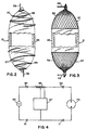
- ultraviolet radiation source 21 includes an envelope 45 of ultraviolet light transmitting material such as pure fused silica (quartz), Vycor brand of high-silica glass or ultraviolet light transmitting borosilicate glass having a transmission band extending to a short wave limit of 253.7 nanometers or less, such as 9741 available from Corning Glass Works.
- the envelopes in FIGS. 2 and 3 have as an outside diameter of 0.157 inch (4.0 millimeters), an inside diameter of 0.078 inch (2.0 millimeters), and an overall length of from 0.590 to 0.787 inch (15.0 to 20.0 millimeters).
- a getter means may be contained within envelope 45.
- a suitable material for the getter means is ST101/ST505 manufactured by SAES Getters S.p.A., Milan, Italy.
- the material chosen for the getter means can serve both as a gettering device and a mercury dispenser if mercury is to be included in the fill.
- a fill material including an inert gas or combinations thereof or in combination with a quantity of mercury is contained within the envelope of the ultraviolet source at a pressure within the range of from about 1 torr to 50 torr.
- the combinations may consist of so-called "Penning Mixtures”.
- the pressure is within the range of from about 5 torr to 15 torr.
- the actual fill pressure of the ultraviolet light source is chosen as a compromise between the desired breakdown voltage of the source (which should ensure ignition with any possible output of the source) and the ultraviolet light output of the source.
- the intensity of the ultraviolet light generated and the breakdown voltage of the source increase as the fill pressure within the source is increased. In some cases, the compromise may be difficult to achieve. It has been discovered that one method of overcoming this problem is to capacitively couple the ends of the ultraviolet light source.
- a solid or gaseous radioactive substance such as a americium 241 (0.9 microcurie) or krypton 85 may also be included in the fill to lower the breakdown voltage. Capacitively coupling the ultraviolet light source eliminates the need for a ballasting resistor in series with the source.
- portions of the opposing ends of envelope 45 of source 21 are capacitively coupled respectively to return lead 43 and outer conductor lead 41 such that ultraviolet source 21 produces ultraviolet radiation during lamp starting when terminals 12 and 14 of lamp 3 are energized.
- the end portions of envelope 45 are in a contiguous relationship with return lead 43 and outer conductor lead 41.
- a contact 57 (FIGS. 1 - 3) is formed at each of the opposing ends of the ultraviolet light source to capacitively couple the ultraviolet light source to the desired current carrying leads (e.g., return lead 43 and outer conductor lead 41) of the lamp.
- contact 57 is formed from separate wires 58 helically wrapped around portions of the external surface of envelope 45 of ultraviolet light source 21.
- both ends of the two separate wires 58 are welded respectively to return lead 43 and outer conductor lead 41.
- the remote ends 59 of contacts 57 are formed so as to be welded respectively, for example, to return lead 43 and outer conductor lead 41 of lamp 3.
- the coupling surface area can be increased by helically wrapping a portion of return lead 43 and a portion of outer conductor lead 41 around portions of the external surface of envelope 45 at the opposing ends of the ultraviolet light source.
- each of the contacts 57 is formed from a mesh sleeve 56 made of a conductive material (e.g., tungsten) and has an attaching wire 48 secured thereto for coupling to the desired current carrying lead within the lamp.
- the lamp was a BU/BD M100 metal halide arc discharge lamp.
- the envelope of the electrodeless ultraviolet light source was formed from quartz glass having an outside diameter of 0.236 inch (6.0 millimeters) and an inside diameter of 0.157 inch (4.0 millimeters).
- the envelope contained a xenon fill at a pressure of approximately 15 torr. Contacts were formed from separate wires on each of the opposing ends of the source as illustrated in FIG. 1.
- test lamps were measured on a known pulse circuit as illustrated in FIG. 4.
- an A.C. voltage source 63 is applied to input terminals 60, 61.
- An inductive ballast 65 such as model no. 71A5380, is connected between input terminal 60 and one of the terminals 69 of lamp 73.
- An ignitor 67 such as model no. LI531, is connected across terminals 69, 71 of lamp 73 as shown in FIG. 4.
- inductive ballast and ignitor are available from Advance Transformer Company, Chicago, Illinois.
- a suitable ignitor produces at least three high voltage pulses per half cycle having an amplitude of at least 3300 volts and a pulse width of at least 2.0 microseconds.
- the starting times of lamps constructed similar to that describe in the above example with and without the ultraviolet light source were measured on the pulse circuit of FIG. 4.
- the lamps measured in the first test were each started twelve times. Results indicated that the metal halide lamp with the ultraviolet light source had an average starting time of approximately 0.01 second compared to an average starting time of 17.3 seconds for a similar lamp without the ultraviolet light source.
- lamps were constructed to determine the effect of mercury within the fill material of the ultraviolet light source.
- the envelope of the ultraviolet light source contained xenon at a pressure of 15 torr.
- the envelope of the source contained 1.0 milligram of mercury and 15 torr argon.
- the lamps of group two i.e., mercury and argon
- the pulse voltage required to start discharge ie., breakdown voltage, is reduced by the introduction of the ultraviolet light source described above.
Landscapes
- Physics & Mathematics (AREA)
- Engineering & Computer Science (AREA)
- Plasma & Fusion (AREA)
- Electromagnetism (AREA)
- Discharge Lamps And Accessories Thereof (AREA)
Abstract
Description
- This application discloses, but does not claim, inventions which are claimed in U.S. Serial No. (Attorney's Docket No. 87-1-001) filed concurrently herewith, and assigned to the Assignee of this application.
- This invention relates to the starting of high pressure metal vapor arc discharge lamps and is especially useful with such lamps having a metallic halide fill.
- High-pressure metal halide arc discharge lamps generally comprise an elongated arc tube containing an ionizable fill and having press seals at each end of the tube. Disposed within the arc tube are two main electrodes, one at each end. The electrodes are generally supported in the press seals and are usually connected to a thin molybdenum ribbon, disposed within the press seal, the purpose of the ribbon being to provide an electrical feedthrough of low thermal expansion, owing to its thinness, while having sufficient current carrying capacity, owing to its width.
- In order to facilitate starting of the gaseous discharge, a starter electrode may be disposed in the arc tube, adjacent to one of the main electrodes.
- Such an electrode is used because a discharge can be ignited between the starter electrode and its adjacent electrode at a much lower starting voltage than is required to ignite a discharge between the two main electrodes. Once the discharge is ignited, the ionized gas provides primary electrons between the two main electrodes and if enough potential is available between the main electrodes a discharge will be formed therebetween. The starter electrode normally has a resistor in series with it to limit the current flowing through the starter electrode after the discharge has started.
- However, the press sealed electrical feedthrough for the starting electrode suffers a sodium electrolysis failure mechanism which leads to premature seal failure and this is made worse at the elevated seal temperatures associated with the newer low color temperature, high efficiency metal halide lamps. For these reasons, the starter electrode approach has been abandoned in favor of a high voltage starting pulse applied directly to the main electrodes of the arc tube. With this method the seal failure problems associated with the starting electrode have been overcome, however, there is a substantial statistical starting time between the time the high voltage is applied to the lamp electrodes and the gas breakdown time when the discharge occurs. By "statistical" starting time, it is meant that the breakdown or starting time for a given lamp and starting circuit is distributed over a range of values, such that, if the voltage is applied N times, the time at which breakdown occurs is distributed over a relatively wide range indicating that in some specific cases, the starting time is relatively short and in some cases, relatively long.
- It is, therefore, an object of the present invention to obviate the disadvantages of the prior art.
- It is still another object of the invention to provide an improved metal halide arc discharge lamp having a decreased statistical starting time between the time the high voltage is applied to the lamp terminals and the time discharge occurs.
- These objects are accomplished in one aspect of the invention by the provision of a metal halide arc discharge lamp comprising an arc tube containing a chemical fill including mercury and metal halides and having first and second electrodes respectively sealed at opposite ends thereof. An outer envelope surrounds the arc tube and has first and second terminals for electrical connection thereto. The lamp further includes means for electrically coupling each of the electrodes of the arc tube to a respective terminal. An electrodeless source of ultraviolet radiation is provided within the outer envelope proximate the arc tube for producing radiation which illuminates the path between the electrodes of the arc tube to decrease the amount of time for generating a gaseous discharge therebetween.
- The source of ultraviolet radiation comprises an envelope of ultraviolet light transmitting material having opposing ends and containing a fill material. One of the opposing ends of the envelope of the source of ultraviolet radiation is capacitively coupled to the means for electrically coupling the first electrode of the arc tube to the first terminal. The other of the opposing ends of the envelope of the source of ultraviolet radiation is capacitively coupled to the means for electrically coupling the second electrode of the arc tube to the second terminal such that the source of ultraviolet radiation produces the ultraviolet radiation during lamp starting when the first and second terminals of the lamp are energized.
- In accordance with further aspects of the present invention, the envelope of the ultraviolet light source is quartz, Vycor or ultraviolet light transmitting borosilicate glass, having a transmission band extending to a short wave limit of 253.7 nanometers or less.
- In accordance with still further teachings of the present invention, the metal halide arc discharge lamp further includes a first contact means coupling the external surface of one of the opposing ends of the envelope of the ultraviolet light source to the means for electrically coupling the first electrode of the arc tube to the first terminal. In a preferred embodiment, the lamp further includes a second contact means coupling the external surface of the other of the opposing ends of the envelope of the ultraviolet light source to the means for electrically coupling the second electrode of the arc tube to the second terminal.
- In accordance with further aspects of the present invention, the first and second contact means each comprise a wire helically wrapped around the external surface of a respective opposing end. In an alternative embodiment, the first and second contacts each comprise a mesh sleeve made of a conductive material.
- In accordance with still further teachings of the present invention, the envelope of the ultraviolet light source contains a predetermined amount (e.g., 0.9 microcurie) of a radioactive substance such as americium 241.
- The invention will become more readily apparent from the following exemplary description in connection with the accompanying drawings, wherein:
- FIG. 1 represents a front elevational view, partially broken away, of an embodiment of a metal halide arc discharge lamp containing an ultraviolet light source according to the present invention;
- FIG. 2 is a front elevational view, partially broken away, of one embodiment of an ultraviolet light source;
- FIG. 3 is a front elevational view, partially broken away, of another embodiment of an ultraviolet light source; and
- FIG. 4 is a schematic diagram of a metal halide arc discharge lamp assembly.
- For a better understanding of the present invention, together with other and further objects, advantages and capabilities thereof, reference is made to the following disclosure and appended Claims in connection with the above-described drawings.
- Referring to the drawings, FIG. 1 illustrates a metal halide
arc discharge lamp 3 which includes an evacuatedouter envelope 7. Evacuatedouter envelope 7 is hermetically sealed to aglass stem member 9. An external base 11, having first andsecond terminals stem member 9 and evacuatedouter envelope 7 for connection to an electrical circuit. The shape ofouter envelope 7 and the particular type of external base 11 used for the lamp may differ from that shown in FIG. 1. A pair of stem leadelectrical conductors stem member 9 and are electrically connected to the terminals of base 11 external of evacuatedouter envelope 7 to provide access for energization of thedischarge lamp 3. Disposed withinouter envelope 7 is anarc tube 33 having an ionizable radiation-generating chemical fill including mercury and metal halides which reach pressures of several atmospheres at normal operating temperatures from 600 to 800°C. One suitable fill comprises mercury, sodium iodide, scandium iodide, and an inert gas such as argon to facilitate starting and warm-up. Preferably, the fill includes iodides of sodium and scandium of a ratio in the range of about 20:1 to 28:1. Arctube 33 also includes first andsecond electrodes outer strap member 39 is affixed to the outer surface ofarc tube 33.Strap member 39 is electrically coupled to and mechanically connected to asupport member 16. -
Support member 16 extends along an axis parallel to the longitudinal axis of thedischarge lamp 3 and includes at one end anannular configuration 19 adjacent and in register with anupper portion 20 of evacuatedenvelope 7. The other end ofsupport member 16 is securely held bystrap member 23 which extends aroundstem member 9, and is electrically isolated from the stem leads 13 and 15. - A heat
loss reducing member 25 in the form of a quartz sleeve surroundsarc tube 33. Heatloss reducing member 25 may include adomed portion 27 positioned closest to base 11 and an open-ended portion 29 which is furthest from and faces away from base 11. Ametal band 31 surrounds and is affixed to heatloss reducing member 25 and is electrically and mechanically connected to thesupport member 16. -
Electrodes arc tube 33, each including ashank portion 17 which extends to amolybdenum foil 18 to which anouter conductor lead tube conductor lead 41 is connected toelectrical conductor 13. Arctube lead 4 is connected to areturn lead 43, that is disposed adjacent heatloss reducing member 25, which is connected toconductor stem lead 15.Electrical conductors terminals envelope 7 thereby completing the lamp operating circuit. -
Getters 61 are positioned withinouter envelope 7 and attached to supportmember 16. - In accordance with the teachings of the instant invention, a metal halide
arc discharge lamp 3 further includes anelectrodeless source 21 of ultraviolet radiation located withinouter envelope 7 andproximate arc tube 33 for producing radiation which illuminates the path betweenelectrodes arc tube 33 to decrease the amount of time for generating a gaseous discharge therebetween. The addition of a source of ultraviolet radiation adjacent the arc tube, which is activated concurrent with the application of high voltage across the electrodes, substantially lowers the statistical starting time and increases the probability of generating a gaseous discharge between the electrodes of the arc tube. The ultraviolet radiation produces photoelectrons in the discharge gap which enhances gas breakdown and hence the initiation of the discharge between the electrodes of the arc tube. - With particular attention to the embodiments illustrated in FIGS. 2 and 3,
ultraviolet radiation source 21 includes anenvelope 45 of ultraviolet light transmitting material such as pure fused silica (quartz), Vycor brand of high-silica glass or ultraviolet light transmitting borosilicate glass having a transmission band extending to a short wave limit of 253.7 nanometers or less, such as 9741 available from Corning Glass Works. Typically, the envelopes in FIGS. 2 and 3 have as an outside diameter of 0.157 inch (4.0 millimeters), an inside diameter of 0.078 inch (2.0 millimeters), and an overall length of from 0.590 to 0.787 inch (15.0 to 20.0 millimeters). - A getter means (not shown) may be contained within
envelope 45. A suitable material for the getter means is ST101/ST505 manufactured by SAES Getters S.p.A., Milan, Italy. The material chosen for the getter means can serve both as a gettering device and a mercury dispenser if mercury is to be included in the fill. - A fill material including an inert gas or combinations thereof or in combination with a quantity of mercury is contained within the envelope of the ultraviolet source at a pressure within the range of from about 1 torr to 50 torr. The combinations may consist of so-called "Penning Mixtures". Preferably, the pressure is within the range of from about 5 torr to 15 torr.
- The actual fill pressure of the ultraviolet light source is chosen as a compromise between the desired breakdown voltage of the source (which should ensure ignition with any possible output of the source) and the ultraviolet light output of the source. The intensity of the ultraviolet light generated and the breakdown voltage of the source increase as the fill pressure within the source is increased. In some cases, the compromise may be difficult to achieve. It has been discovered that one method of overcoming this problem is to capacitively couple the ends of the ultraviolet light source. A solid or gaseous radioactive substance such a americium 241 (0.9 microcurie) or krypton 85 may also be included in the fill to lower the breakdown voltage. Capacitively coupling the ultraviolet light source eliminates the need for a ballasting resistor in series with the source.
- In the embodiment as illustrated in FIG. 1, portions of the opposing ends of
envelope 45 ofsource 21 are capacitively coupled respectively to returnlead 43 andouter conductor lead 41 such thatultraviolet source 21 produces ultraviolet radiation during lamp starting whenterminals lamp 3 are energized. Preferably, the end portions ofenvelope 45 are in a contiguous relationship withreturn lead 43 andouter conductor lead 41. - To further increase the coupling surface area to
envelope 45, a contact 57 (FIGS. 1 - 3) is formed at each of the opposing ends of the ultraviolet light source to capacitively couple the ultraviolet light source to the desired current carrying leads (e.g., returnlead 43 and outer conductor lead 41) of the lamp. - In the embodiment illustrated in FIGS. 1 and 2, contact 57 is formed from
separate wires 58 helically wrapped around portions of the external surface ofenvelope 45 ofultraviolet light source 21. In FIG. 1, both ends of the twoseparate wires 58 are welded respectively to returnlead 43 andouter conductor lead 41. In FIG. 2, the remote ends 59 ofcontacts 57 are formed so as to be welded respectively, for example, to returnlead 43 andouter conductor lead 41 oflamp 3. Alternatively, the coupling surface area can be increased by helically wrapping a portion ofreturn lead 43 and a portion ofouter conductor lead 41 around portions of the external surface ofenvelope 45 at the opposing ends of the ultraviolet light source. In the embodiment shown in FIG. 3, each of thecontacts 57 is formed from amesh sleeve 56 made of a conductive material (e.g., tungsten) and has an attachingwire 48 secured thereto for coupling to the desired current carrying lead within the lamp. - In a typical but non-limitative example of a metal halide arc discharge lamp containing a source of ultraviolet light in accordance with the teachings of the present invention, the lamp was a BU/BD M100 metal halide arc discharge lamp. The envelope of the electrodeless ultraviolet light source was formed from quartz glass having an outside diameter of 0.236 inch (6.0 millimeters) and an inside diameter of 0.157 inch (4.0 millimeters). The envelope contained a xenon fill at a pressure of approximately 15 torr. Contacts were formed from separate wires on each of the opposing ends of the source as illustrated in FIG. 1.
- The dramatic effect of the ultraviolet radiation on the starting time between voltage application and the current flow through the lamp may be more fully appreciated by a comparison of the data of starting times for lamps constructed with and without an ultraviolet light source of the present invention. Test lamps were measured on a known pulse circuit as illustrated in FIG. 4. As shown in FIG. 4, an
A.C. voltage source 63 is applied to inputterminals inductive ballast 65, such as model no. 71A5380, is connected betweeninput terminal 60 and one of theterminals 69 oflamp 73. Anignitor 67, such as model no. LI531, is connected acrossterminals lamp 73 as shown in FIG. 4. The above-mentioned inductive ballast and ignitor are available from Advance Transformer Company, Chicago, Illinois. A suitable ignitor produces at least three high voltage pulses per half cycle having an amplitude of at least 3300 volts and a pulse width of at least 2.0 microseconds. - In a first test, the starting times of lamps constructed similar to that describe in the above example with and without the ultraviolet light source were measured on the pulse circuit of FIG. 4. The lamps measured in the first test were each started twelve times. Results indicated that the metal halide lamp with the ultraviolet light source had an average starting time of approximately 0.01 second compared to an average starting time of 17.3 seconds for a similar lamp without the ultraviolet light source.
- In a second test, the starting times of lamps constructed similar to that described in the first test above except the envelope of the ultraviolet light source contained approximately 0.9 microcurie of americium 241. This lamp had an average starting time for twelve starts of approximately 0.013 second.
- In a third test, lamps were constructed to determine the effect of mercury within the fill material of the ultraviolet light source. In a first group, the envelope of the ultraviolet light source contained xenon at a pressure of 15 torr. In a second group, the envelope of the source contained 1.0 milligram of mercury and 15 torr argon. The lamps of group two (i.e., mercury and argon) had an average starting time of approximately 80 percent less than group one lamps (i.e., xenon).
- The pulse voltage required to start discharge, ie., breakdown voltage, is reduced by the introduction of the ultraviolet light source described above.
- While there have been shown and described what are at present considered to be the preferred embodiments of the invention, it will be apparent to those skilled in the art that various changes and modifications can be made herein without departing from the scope of the invention. The embodiments shown in the drawings and described in the specification are intended to best explain the principles of the invention and its practical application to hereby enable others in the art to best utilize the invention in various embodiments and with various modifications as are suited to the particular use contemplated.
Claims (23)
an arc tube containing a chemical fill including mercury and metal halides and having first and second electrodes respectively sealed at opposite ends thereof;
an outer envelope surrounding said arc tube and having first and second terminals for electrical connection thereto;
means for electrically coupling said first electrode of said arc tube to said first terminal;
means for electrically coupling said second electrode of said arc tube to said second terminal; and
an electrodeless source of ultraviolet radiation within said outer envelope proximate said arc tube for producing radiation which illuminates the path between said electrodes of said arc tube to decrease the amount of time for generating a gaseous discharge therebetween, said source of ultraviolet radiation comprising an envelope of ultraviolet light transmitting material having opposing ends, a fill material contained within said envelope of said source of ultraviolet radiation, one of said opposing ends of said envelope of said source of ultraviolet radiation being capacitively coupled to said means for electrically coupling said first electrode of said arc tube to said first terminal, the other of said opposing ends of said envelope of said source of ultraviolet radiation being capacitively coupled to said means for electrically coupling said second electrode of said arc tube to said second terminal such that said source of ultraviolet radiation produces said ultraviolet radiation during lamp starting when said first and second terminals of said lamp are energized.
a metal halide arc discharge lamp including an arc tube containing a chemical fill including mercury and metal halides and having first and second electrodes respectively sealed at opposite ends thereof, an outer envelope surrounding said arc tube and having first and second terminals for electrical connection thereto, means for electrically coupling said first electrode of said arc tube to said first terminal, means for electrically coupling said second electrode of said arc tube to said second terminal, and an electrodeless source of ultraviolet radiation within said outer envelope proximate said arc tube for producing radiation which illuminates the path between said electrodes of said arc tube to decrease the amount of time for generating a gaseous discharge therebetween, said source of ultraviolet radiation comprising an envelope of ultraviolet light transmitting material having opposing ends, a fill material contained within said envelope of said source of ultraviolet radiation, one of said opposing ends of said envelope of said source of ultraviolet radiating being capacitively coupled to said means for electrically coupling said first electrode of said arc tube to said first terminal, the other of said opposing ends of said envelope of said source of ultraviolet radiation being capacitively coupled to said means for electrically coupling said second electrode of said arc tube to said second terminal such that said source of ultraviolet radiation produces said ultraviolet radiation during lamp starting when said first and second terminals of said lamp are energized;
input terminals operable to be connected across said A.C. source;
an inductive ballast connected between one of said input terminals and said first terminal of said metal halide arc discharge lamp; and
an ignitor means for generating high voltage pulses connected across said metal halide arc discharge lamp.
an envelope of ultraviolet light transmitting material having opposing ends;
a fill material contained within said envelope of said source; and
first and second contacts respectively coupling the external surface of said opposing ends of said envelope.
Applications Claiming Priority (2)
| Application Number | Priority Date | Filing Date | Title |
|---|---|---|---|
| US07/111,396 US4812714A (en) | 1987-10-22 | 1987-10-22 | Arc discharge lamp with electrodeless ultraviolet radiation starting source |
| US111396 | 1987-10-22 |
Publications (3)
| Publication Number | Publication Date |
|---|---|
| EP0313028A2 true EP0313028A2 (en) | 1989-04-26 |
| EP0313028A3 EP0313028A3 (en) | 1991-01-30 |
| EP0313028B1 EP0313028B1 (en) | 1995-07-05 |
Family
ID=22338307
Family Applications (1)
| Application Number | Title | Priority Date | Filing Date |
|---|---|---|---|
| EP88117416A Expired - Lifetime EP0313028B1 (en) | 1987-10-22 | 1988-10-19 | Arc discharge lamp with electrodeless ultraviolet radiation starting source |
Country Status (5)
| Country | Link |
|---|---|
| US (1) | US4812714A (en) |
| EP (1) | EP0313028B1 (en) |
| JP (1) | JPH01134849A (en) |
| CA (1) | CA1302476C (en) |
| DE (1) | DE3854112T2 (en) |
Cited By (4)
| Publication number | Priority date | Publication date | Assignee | Title |
|---|---|---|---|---|
| EP0489532A1 (en) * | 1990-12-04 | 1992-06-10 | General Electric Company | Electrodeless discharge lamp |
| EP1227511A1 (en) * | 2001-01-30 | 2002-07-31 | Stanley Electric Co., Ltd. | High pressure electric discharge lamp |
| WO2008135084A1 (en) * | 2007-05-04 | 2008-11-13 | Osram Gesellschaft mit beschränkter Haftung | High-pressure discharge lamp having a starting aid |
| CN100542367C (en) * | 2002-08-22 | 2009-09-16 | 熔合Uv系统公司 | The ultra-violet lamp of radio-frequency driven |
Families Citing this family (18)
| Publication number | Priority date | Publication date | Assignee | Title |
|---|---|---|---|---|
| US4987344A (en) * | 1990-02-05 | 1991-01-22 | Gte Products Corporation | Arc discharge lamp with internal starter |
| US5959404A (en) * | 1995-01-12 | 1999-09-28 | Osram Sylvania Inc. | Starting aid for metal halide lamps |
| US5614151A (en) * | 1995-06-07 | 1997-03-25 | R Squared Holding, Inc. | Electrodeless sterilizer using ultraviolet and/or ozone |
| US5990599A (en) * | 1997-12-18 | 1999-11-23 | Philips Electronics North America Corp. | High-pressure discharge lamp having UV radiation source for enhancing ignition |
| JP4112638B2 (en) * | 1998-03-19 | 2008-07-02 | コーニンクレッカ フィリップス エレクトロニクス エヌ ヴィ | Unit comprising a short arc discharge lamp with a starting antenna |
| EP1105916B1 (en) * | 1999-06-16 | 2004-12-01 | Koninklijke Philips Electronics N.V. | Metal halide lamp |
| JP4568989B2 (en) * | 2000-11-15 | 2010-10-27 | 東芝ライテック株式会社 | High pressure discharge lamp and lighting device |
| US6908586B2 (en) * | 2001-06-27 | 2005-06-21 | Fusion Uv Systems, Inc. | Free radical polymerization method having reduced premature termination, apparatus for performing the method and product formed thereby |
| EP1449237A2 (en) * | 2001-11-15 | 2004-08-25 | Koninklijke Philips Electronics N.V. | High-pressure discharge lamp |
| JP3528836B2 (en) * | 2002-01-09 | 2004-05-24 | ウシオ電機株式会社 | Discharge lamp |
| JP2005347060A (en) * | 2004-06-02 | 2005-12-15 | Iwasaki Electric Co Ltd | High-pressure discharge lamp and light source system |
| DE102006022970B3 (en) * | 2006-05-11 | 2007-11-22 | Fraunhofer-Gesellschaft zur Förderung der angewandten Forschung e.V. | UV-light source |
| US7915825B2 (en) * | 2006-11-07 | 2011-03-29 | Osram Sylvania Inc. | Starting aid for discharge lamp |
| JP2008140614A (en) * | 2006-11-30 | 2008-06-19 | Osram Melco Toshiba Lighting Kk | High-pressure metal vapor discharge lamp and lighting fixture |
| DE102010031280A1 (en) | 2010-07-13 | 2012-01-19 | Osram Gesellschaft mit beschränkter Haftung | High pressure discharge lamp with ignition aid |
| WO2012110074A1 (en) | 2011-02-14 | 2012-08-23 | Osram Ag | High-pressure discharge lamp comprising a halogen-containing ignition aid |
| US10475636B2 (en) | 2017-09-28 | 2019-11-12 | Nxp Usa, Inc. | Electrodeless lamp system and methods of operation |
| US11299405B2 (en) | 2017-09-28 | 2022-04-12 | Nxp Usa, Inc. | Purification apparatus with electrodeless bulb and methods of operation |
Citations (15)
| Publication number | Priority date | Publication date | Assignee | Title |
|---|---|---|---|---|
| US2629839A (en) * | 1948-05-10 | 1953-02-24 | William B Greenlee | Capacitive lighting system |
| FR1234391A (en) * | 1958-07-29 | 1960-10-17 | Philips Nv | Light source in the far ultraviolet |
| US3873884A (en) * | 1973-03-01 | 1975-03-25 | Perkin Elmer Corp | Electrodeless discharge lamp and power coupler therefor |
| US3997816A (en) * | 1975-04-21 | 1976-12-14 | Gte Laboratories Incorporated | Starting assist device for an electrodeless light source |
| FR2448224A1 (en) * | 1979-02-02 | 1980-08-29 | Gte Laboratories Inc | LAMP WITH RADIOACTIVITY PRIMING ELECTRODE |
| JPS55143768A (en) * | 1979-04-27 | 1980-11-10 | Toshiba Corp | Metal vapor discharge lamp and its manufacture |
| GB2066560A (en) * | 1979-11-28 | 1981-07-08 | Mitsubishi Electric Corp | Discharge lamp |
| JPS59127356A (en) * | 1983-01-06 | 1984-07-23 | Etou Denki Kk | Underwater discharge lamp for fish luring |
| GB2140229A (en) * | 1983-05-17 | 1984-11-21 | Emi Plc Thorn | Discharge lamp start and supply circuit |
| JPS6124138A (en) * | 1984-07-11 | 1986-02-01 | Matsushita Electronics Corp | Metal halide lamp |
| DE3518299A1 (en) * | 1985-05-22 | 1986-11-27 | Paul 7030 Böblingen Gerlach | Gas-discharge lamp |
| JPS6313255A (en) * | 1986-07-03 | 1988-01-20 | Canon Inc | Lighting equipment |
| US4721888A (en) * | 1984-12-27 | 1988-01-26 | Gte Laboratories Incorporated | Arc discharge lamp with ultraviolet enhanced starting circuit |
| JPS6362147A (en) * | 1986-09-02 | 1988-03-18 | Matsushita Electronics Corp | Metal halide lamp |
| JPS63158737A (en) * | 1986-12-22 | 1988-07-01 | Toshiba Corp | Metallic vapor discharge lamp |
Family Cites Families (8)
| Publication number | Priority date | Publication date | Assignee | Title |
|---|---|---|---|---|
| US3226597A (en) * | 1963-09-04 | 1965-12-28 | Gen Electric | High pressure metal vapor discharge lamp |
| US3900761A (en) * | 1973-11-30 | 1975-08-19 | Gte Sylvania Inc | High intensity metal arc discharge lamp |
| US4041352A (en) * | 1976-07-14 | 1977-08-09 | Gte Laboratories Incorporated | Automatic starting system for solid state powered electrodeless lamps |
| US4053814A (en) * | 1976-07-14 | 1977-10-11 | Gte Laboratories Incorporated | Continuous automatic starting assist uv circuit for microwave powered electrodeless lamps |
| US4097777A (en) * | 1976-11-10 | 1978-06-27 | General Electric Company | Arc discharge lamp including starting circuit |
| US4328446A (en) * | 1980-04-11 | 1982-05-04 | Gte Laboratories Incorporated | Method and apparatus for starting high intensity discharge lamps |
| US4325004A (en) * | 1980-10-02 | 1982-04-13 | Gte Laboratories Incorporated | Method and apparatus for starting high intensity discharge lamps |
| US4355261A (en) * | 1980-12-15 | 1982-10-19 | Gte Products Corporation | Discharge lamp with integral starter |
-
1987
- 1987-10-22 US US07/111,396 patent/US4812714A/en not_active Expired - Fee Related
-
1988
- 1988-09-22 CA CA000578128A patent/CA1302476C/en not_active Expired - Lifetime
- 1988-10-19 DE DE3854112T patent/DE3854112T2/en not_active Expired - Fee Related
- 1988-10-19 EP EP88117416A patent/EP0313028B1/en not_active Expired - Lifetime
- 1988-10-20 JP JP63263029A patent/JPH01134849A/en active Pending
Patent Citations (15)
| Publication number | Priority date | Publication date | Assignee | Title |
|---|---|---|---|---|
| US2629839A (en) * | 1948-05-10 | 1953-02-24 | William B Greenlee | Capacitive lighting system |
| FR1234391A (en) * | 1958-07-29 | 1960-10-17 | Philips Nv | Light source in the far ultraviolet |
| US3873884A (en) * | 1973-03-01 | 1975-03-25 | Perkin Elmer Corp | Electrodeless discharge lamp and power coupler therefor |
| US3997816A (en) * | 1975-04-21 | 1976-12-14 | Gte Laboratories Incorporated | Starting assist device for an electrodeless light source |
| FR2448224A1 (en) * | 1979-02-02 | 1980-08-29 | Gte Laboratories Inc | LAMP WITH RADIOACTIVITY PRIMING ELECTRODE |
| JPS55143768A (en) * | 1979-04-27 | 1980-11-10 | Toshiba Corp | Metal vapor discharge lamp and its manufacture |
| GB2066560A (en) * | 1979-11-28 | 1981-07-08 | Mitsubishi Electric Corp | Discharge lamp |
| JPS59127356A (en) * | 1983-01-06 | 1984-07-23 | Etou Denki Kk | Underwater discharge lamp for fish luring |
| GB2140229A (en) * | 1983-05-17 | 1984-11-21 | Emi Plc Thorn | Discharge lamp start and supply circuit |
| JPS6124138A (en) * | 1984-07-11 | 1986-02-01 | Matsushita Electronics Corp | Metal halide lamp |
| US4721888A (en) * | 1984-12-27 | 1988-01-26 | Gte Laboratories Incorporated | Arc discharge lamp with ultraviolet enhanced starting circuit |
| DE3518299A1 (en) * | 1985-05-22 | 1986-11-27 | Paul 7030 Böblingen Gerlach | Gas-discharge lamp |
| JPS6313255A (en) * | 1986-07-03 | 1988-01-20 | Canon Inc | Lighting equipment |
| JPS6362147A (en) * | 1986-09-02 | 1988-03-18 | Matsushita Electronics Corp | Metal halide lamp |
| JPS63158737A (en) * | 1986-12-22 | 1988-07-01 | Toshiba Corp | Metallic vapor discharge lamp |
Non-Patent Citations (6)
| Title |
|---|
| PATENT ABSTRACTS OF JAPAN vol. 10, no. 175 (E-413)(2231) 20 June 1986, & JP-A-61 024 138 (MATSUSHITA DENSHI KOGYO K.K.) 1 February 1986, * |
| PATENT ABSTRACTS OF JAPAN vol. 12, no. 217 (E-624)(3064) 21 June 1988, & JP-A-63 013 255 (CANON INC.) 20 January 1988, * |
| PATENT ABSTRACTS OF JAPAN vol. 12, no. 285 (E-642)(3132) 4 August 1988, & JP-A-63 062 147 (MATSUSHITA ELECTRONICS CORP.) 18 March 1988, * |
| PATENT ABSTRACTS OF JAPAN vol. 12, no. 420 (E-679)(3267) 8 November 1988, & JP-A-63 158 737 (TOSHIBA CORP.) 1 July 1988, * |
| PATENT ABSTRACTS OF JAPAN vol. 5, no. 15 (E-43) 29 January 1981, & JP-A-55 143 768 (TOSHIBA CORP.) 10 November 1980, * |
| PATENT ABSTRACTS OF JAPAN vol. 8, no. 250 (E-279) 16 November 1984, & JP-A-59 127 356 (ETOU DENKI KK) 23 July 1984, * |
Cited By (6)
| Publication number | Priority date | Publication date | Assignee | Title |
|---|---|---|---|---|
| EP0489532A1 (en) * | 1990-12-04 | 1992-06-10 | General Electric Company | Electrodeless discharge lamp |
| EP1227511A1 (en) * | 2001-01-30 | 2002-07-31 | Stanley Electric Co., Ltd. | High pressure electric discharge lamp |
| US6624580B2 (en) | 2001-01-31 | 2003-09-23 | Stanley Electric Co., Ltd. | High pressure electric discharge lamp |
| CN100542367C (en) * | 2002-08-22 | 2009-09-16 | 熔合Uv系统公司 | The ultra-violet lamp of radio-frequency driven |
| WO2008135084A1 (en) * | 2007-05-04 | 2008-11-13 | Osram Gesellschaft mit beschränkter Haftung | High-pressure discharge lamp having a starting aid |
| US8129890B2 (en) | 2007-05-04 | 2012-03-06 | Osram Ag | High-pressure discharge lamp having a starting aid |
Also Published As
| Publication number | Publication date |
|---|---|
| EP0313028A3 (en) | 1991-01-30 |
| US4812714A (en) | 1989-03-14 |
| DE3854112D1 (en) | 1995-08-10 |
| DE3854112T2 (en) | 1996-03-07 |
| EP0313028B1 (en) | 1995-07-05 |
| CA1302476C (en) | 1992-06-02 |
| JPH01134849A (en) | 1989-05-26 |
Similar Documents
| Publication | Publication Date | Title |
|---|---|---|
| US4818915A (en) | Arc discharge lamp with ultraviolet radiation starting source | |
| US4812714A (en) | Arc discharge lamp with electrodeless ultraviolet radiation starting source | |
| US4987344A (en) | Arc discharge lamp with internal starter | |
| US5990599A (en) | High-pressure discharge lamp having UV radiation source for enhancing ignition | |
| US5661367A (en) | High pressure series arc discharge lamp construction with simplified starting aid | |
| US5493167A (en) | Lamp assembly with shroud employing insulator support stops | |
| JP3208087B2 (en) | Metal halide lamp | |
| EP0596735B1 (en) | Arc tube with a starting source | |
| JP2000030663A (en) | Arc tube for discharge lamp | |
| US5550421A (en) | Discharge lamp with enhanced performance and improved containment | |
| EP0722184B1 (en) | Starting aid for metal halide lamps | |
| US4355261A (en) | Discharge lamp with integral starter | |
| US3828214A (en) | Plasma enshrouded electric discharge device | |
| US5397259A (en) | Ultraviolet radiation starting source and method of manufacture | |
| US3307069A (en) | Electric discharge lamp | |
| US3721845A (en) | Sodium vapor lamp having improved starting means | |
| US5130602A (en) | High-pressure gas discharge lamp | |
| CA2613730C (en) | Starting aid for low wattage metal halide lamps | |
| US4677343A (en) | Sealed beam lamps | |
| US5248273A (en) | Method of fabricating ultraviolet radiation starting source | |
| US3706898A (en) | High pressure electric discharge lamp | |
| US3895248A (en) | Gas discharge device with glow discharge igniting structure | |
| JPH01243362A (en) | Small fluorescent lamp |
Legal Events
| Date | Code | Title | Description |
|---|---|---|---|
| PUAI | Public reference made under article 153(3) epc to a published international application that has entered the european phase |
Free format text: ORIGINAL CODE: 0009012 |
|
| 17P | Request for examination filed |
Effective date: 19881118 |
|
| AK | Designated contracting states |
Kind code of ref document: A2 Designated state(s): BE DE FR GB NL |
|
| PUAL | Search report despatched |
Free format text: ORIGINAL CODE: 0009013 |
|
| AK | Designated contracting states |
Kind code of ref document: A3 Designated state(s): BE DE FR GB NL |
|
| 17Q | First examination report despatched |
Effective date: 19930715 |
|
| GRAA | (expected) grant |
Free format text: ORIGINAL CODE: 0009210 |
|
| AK | Designated contracting states |
Kind code of ref document: B1 Designated state(s): BE DE FR GB NL |
|
| REF | Corresponds to: |
Ref document number: 3854112 Country of ref document: DE Date of ref document: 19950810 |
|
| ET | Fr: translation filed | ||
| PLBE | No opposition filed within time limit |
Free format text: ORIGINAL CODE: 0009261 |
|
| STAA | Information on the status of an ep patent application or granted ep patent |
Free format text: STATUS: NO OPPOSITION FILED WITHIN TIME LIMIT |
|
| 26N | No opposition filed | ||
| PGFP | Annual fee paid to national office [announced via postgrant information from national office to epo] |
Ref country code: BE Payment date: 20001009 Year of fee payment: 13 |
|
| PGFP | Annual fee paid to national office [announced via postgrant information from national office to epo] |
Ref country code: GB Payment date: 20001012 Year of fee payment: 13 |
|
| PGFP | Annual fee paid to national office [announced via postgrant information from national office to epo] |
Ref country code: FR Payment date: 20001016 Year of fee payment: 13 |
|
| PGFP | Annual fee paid to national office [announced via postgrant information from national office to epo] |
Ref country code: NL Payment date: 20001031 Year of fee payment: 13 |
|
| PGFP | Annual fee paid to national office [announced via postgrant information from national office to epo] |
Ref country code: DE Payment date: 20010102 Year of fee payment: 13 |
|
| REG | Reference to a national code |
Ref country code: GB Ref legal event code: 732E |
|
| PG25 | Lapsed in a contracting state [announced via postgrant information from national office to epo] |
Ref country code: GB Free format text: LAPSE BECAUSE OF NON-PAYMENT OF DUE FEES Effective date: 20011019 |
|
| PG25 | Lapsed in a contracting state [announced via postgrant information from national office to epo] |
Ref country code: BE Free format text: LAPSE BECAUSE OF NON-PAYMENT OF DUE FEES Effective date: 20011031 |
|
| REG | Reference to a national code |
Ref country code: GB Ref legal event code: IF02 |
|
| BERE | Be: lapsed |
Owner name: GTE PRODUCTS CORP. Effective date: 20011031 |
|
| PG25 | Lapsed in a contracting state [announced via postgrant information from national office to epo] |
Ref country code: NL Free format text: LAPSE BECAUSE OF NON-PAYMENT OF DUE FEES Effective date: 20020501 |
|
| GBPC | Gb: european patent ceased through non-payment of renewal fee |
Effective date: 20011019 |
|
| PG25 | Lapsed in a contracting state [announced via postgrant information from national office to epo] |
Ref country code: FR Free format text: LAPSE BECAUSE OF NON-PAYMENT OF DUE FEES Effective date: 20020628 |
|
| NLV4 | Nl: lapsed or anulled due to non-payment of the annual fee |
Effective date: 20020501 |
|
| PG25 | Lapsed in a contracting state [announced via postgrant information from national office to epo] |
Ref country code: DE Free format text: LAPSE BECAUSE OF NON-PAYMENT OF DUE FEES Effective date: 20020702 |
|
| REG | Reference to a national code |
Ref country code: FR Ref legal event code: ST |