EP0314268A1 - Casing patch method and apparatus - Google Patents
Casing patch method and apparatus Download PDFInfo
- Publication number
- EP0314268A1 EP0314268A1 EP88305738A EP88305738A EP0314268A1 EP 0314268 A1 EP0314268 A1 EP 0314268A1 EP 88305738 A EP88305738 A EP 88305738A EP 88305738 A EP88305738 A EP 88305738A EP 0314268 A1 EP0314268 A1 EP 0314268A1
- Authority
- EP
- European Patent Office
- Prior art keywords
- casing
- spear
- fish
- annular member
- tool
- Prior art date
- Legal status (The legal status is an assumption and is not a legal conclusion. Google has not performed a legal analysis and makes no representation as to the accuracy of the status listed.)
- Granted
Links
Images


Classifications
-
- E—FIXED CONSTRUCTIONS
- E21—EARTH DRILLING; MINING
- E21B—EARTH DRILLING, e.g. DEEP DRILLING; OBTAINING OIL, GAS, WATER, SOLUBLE OR MELTABLE MATERIALS OR A SLURRY OF MINERALS FROM WELLS
- E21B29/00—Cutting or destroying pipes, packers, plugs, or wire lines, located in boreholes or wells, e.g. cutting of damaged pipes, of windows; Deforming of pipes in boreholes or wells; Reconditioning of well casings while in the ground
- E21B29/10—Reconditioning of well casings, e.g. straightening
Definitions
- connection is attempted.
- This type of connection is also used in the event the casing has stuck to adjust the vertical position of the top of the casing.
- Such connection is referred to herein as a casing patch. It is preferred that the casing patch be made to a hanger or other suitable equipment which can be supported within a wellhead housing and that the casing be held in tension during the making of the patch.
- a particularly advantageous manner of providing such casing patch is to provide a cold forging tool which is positioned within the casing and a hanger having a gripping and sealing interior contour positioned around the casing near its upper end.
- U. S. Patent Application Serial No. 044,409, filed April 30, 1987 discloses a cold forging method, apparatus and tool therefor which can be used to make a casing patch.
- Casing which is in a well bore as a "fish" can be engaged internally by a device commonly referred to as a spear and when the spear has engaged, tension can be exerted on the string in which the spear is engaged to exert a tension on the casing.
- a device commonly referred to as a spear When the spear has engaged, tension can be exerted on the string in which the spear is engaged to exert a tension on the casing.
- One disadvantage which has been encountered with the use of spears to tension casing is that considerable radial loading may be necessary on the casing and to prevent slipping of the spear, the spear slips are highly loaded. Also, the tensioning can also increase the loading of the slips against the interior of the casing. Such high slip loading has caused excessive deformation of the casing in the past.
- the present invention relates to a method and an apparatus for making a casing patch while the casing is held under tension.
- the method includes the steps of lowering a casing patch tool to position the annular member to which the upper end of the casing is to be connected and a casing protection collar both in surrounding relationship to the upper end of the casing and with the cold forging tool and the tensioning spear within the casing, setting the spear within the casing at a level surrounded by the casing protection collar, pulling on the spear to tension the casing, and cold forging the casing into tight gripping and sealing engagement with the annular member.
- the apparatus includes the annular member to which the casing is to be connected, a guide sleeve on the lower end of the annular member sized to be lowered in the well bore and into surrounding relation to the upper end of the casing, a cold forging tool, a spear and a protection collar positioned within said annular member at the level of the spear so that it surrounds the casing to prevent excessive deformation on setting and tensioning by the spear. It is also a part of this invention to provide an improved method and apparatus to protect the casing from excessive formation by surrounding its exterior in the area of spear engagement with a protection collar.
- Another object is to provide an improved method and apparatus for effecting a casing patch in which the unit is tensioned by a spear which engages within the upper end of the casing so that the casing below such spear engagement is under tension as it is cold forged into tight gripping and sealing engagement within an annular member surrounding the casing.
- a further object is to provide an improved spear and method of tensioning a string which protects the string being engaged by the spear from excessive deformation by the spear slip loading and the tension loads.
- outer casing 10 is positioned within a well bore and inner casing fish 14 is positioned within outer casing 10.
- Annular member 16 having an internal contoured recess 18 has guide sleeve 20 secured to its lower end as by threads 22.
- the lower interior of guide sleeve 20 is tapered so that it will cause the upper end of inner casing fish 14 to move into the interior of guide sleeve 20.
- Protection collar 24 is positioned on upwardly facing shoulder 26 on the upper end of annular member 16 and within tubular connector 28 which is threaded onto the upper exterior of annular member 16.
- the inner assembly is lowered through string 30 on drill pipe 32 to positioned spear 34 within the upper end of casing fish 14 and at a level at which casing fish 14 is surrounded by protection collar 24, forging tool 36 is within casing fish 14 below spear 34 and at least partially below the lower level of contoured recess 18 as shown in FIGURE 3.
- Pump and instrument pod 38 is positioned above spear 34 on drill pipe 32.
- Tubing 40 connects from pod 38 through spear 34 into tool 36 to provide the pressure fluid for the actuation of tool 36.
- Tool 36 is preferred to be a tool such as is disclosed in the copending application Serial No. , , filed October , 1987.
- Spear 34 is any suitable available spear which includes outer slips 42 and an inner mandrel 44 which moves axially of the slips 42 to wedge them outward into gripping engagement with the interior of the upper end of casing fish 14.
- tool 36 is positioned below its desired position with respect to contour recess 18 by a distance which includes the anticipated elongation of the casing fish 14 and the distance the spear mandrel 44 is estimated to travel to properly and completely set slips 42.
- FIGURE 4 illustrates the relative position of the inner and outer assemblies after the spear mandrel 44 has been moved upwardly within slips 42 causing slips 42 to be moved outward into tight gripping engagement within the upper end of casing fish 14.
- tool 36 has been moved upwardly within annular member 16 the distance of the setting movement of spear mandrel 44 but tool 36 is still below the upper end of contoured recess 18.
- the gripping engagement of spear 34 into the interior of casing 14 causes casing 14 to be forced outward into engagement with protection collar 24.
- Collar 24 is sufficiently thick and strong so that further distortion of casing 14 responsive to the gripping forces of spear 34 is prevented.
- FIGURE 5 illustrates the positions of the components after spear 34 has been set and lifted by drill pipe 32 to effect the desired amount of tension in casing fish 14. This has caused casing fish 14 to elongate and inner assembly to be raised so that tool 36 is positioned at the desired level within annular member 16. In this position the forging of casing fish 14 is outward into internal contoured recess 18 of annular member 16. This forging step is illustrated in FIGURE 6.
- When such forging is completed responsive to the delivery of fluid under pressure from pod 38 through tubing 40 into tool 36 so that the resilient packing is forced outward forcing the portion of casing 14 which it engages outward into tight sealing and gripping engagement with internal contoured recess 18.
- Lower packing seal 52 is set within casing 14 at a position below the portion of casing 14 which has been forged into engagement with contoured recess 18 within annular member 16. To test the sealing of the forged connection, pressure is delivered through drill string 48 and out its central opening 54. Since blind cap 56 is secured to the lower end of string 48, any loss of pressure notice at the surface in string 48 after it has been fully pressurized will indicated a leakage in the forged connection.
- the use of the protection collar with the spear to protect the casing from excessive deformation responsive to the setting of the spear and its tension loading which increases the gripping loading on the casing may be used in applications other than the method and apparatus for providing a casing patch.
Abstract
Description
- When a casing within a well bore has been lost or cut loose for any reason, a connection to the upper end of the casing is attempted. This type of connection is also used in the event the casing has stuck to adjust the vertical position of the top of the casing. Such connection is referred to herein as a casing patch. It is preferred that the casing patch be made to a hanger or other suitable equipment which can be supported within a wellhead housing and that the casing be held in tension during the making of the patch.
- A particularly advantageous manner of providing such casing patch is to provide a cold forging tool which is positioned within the casing and a hanger having a gripping and sealing interior contour positioned around the casing near its upper end. U. S. Patent Application Serial No. 044,409, filed April 30, 1987 discloses a cold forging method, apparatus and tool therefor which can be used to make a casing patch.
- Casing which is in a well bore as a "fish" can be engaged internally by a device commonly referred to as a spear and when the spear has engaged, tension can be exerted on the string in which the spear is engaged to exert a tension on the casing. One disadvantage which has been encountered with the use of spears to tension casing is that considerable radial loading may be necessary on the casing and to prevent slipping of the spear, the spear slips are highly loaded. Also, the tensioning can also increase the loading of the slips against the interior of the casing. Such high slip loading has caused excessive deformation of the casing in the past.
- The present invention relates to a method and an apparatus for making a casing patch while the casing is held under tension. The method includes the steps of lowering a casing patch tool to position the annular member to which the upper end of the casing is to be connected and a casing protection collar both in surrounding relationship to the upper end of the casing and with the cold forging tool and the tensioning spear within the casing, setting the spear within the casing at a level surrounded by the casing protection collar, pulling on the spear to tension the casing, and cold forging the casing into tight gripping and sealing engagement with the annular member. The apparatus includes the annular member to which the casing is to be connected, a guide sleeve on the lower end of the annular member sized to be lowered in the well bore and into surrounding relation to the upper end of the casing, a cold forging tool, a spear and a protection collar positioned within said annular member at the level of the spear so that it surrounds the casing to prevent excessive deformation on setting and tensioning by the spear. It is also a part of this invention to provide an improved method and apparatus to protect the casing from excessive formation by surrounding its exterior in the area of spear engagement with a protection collar.
- It is an object of the present invention to provide an improved method and apparatus for the installation of a casing patch which is done with the casing under tension and without excessive deformation to the casing.
- Another object is to provide an improved method and apparatus for effecting a casing patch in which the unit is tensioned by a spear which engages within the upper end of the casing so that the casing below such spear engagement is under tension as it is cold forged into tight gripping and sealing engagement within an annular member surrounding the casing.
- A further object is to provide an improved spear and method of tensioning a string which protects the string being engaged by the spear from excessive deformation by the spear slip loading and the tension loads.
- These and other objects and advantages of the present invention are hereinafter set forth and explained with reference to the drawings wherein:
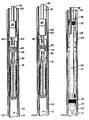
- FIGURE 1 is a detail sectional view of a well bore showing a casing in the lower portion thereof and an annular member with a protection collar supported within said annular member and a guide sleeve on lower end of the annular member being lowered within the well bore into surrounding relationship to the upper end of the casing fish.
- FIGURE 2 is a view similar to FIGURE 1 but illustrates the position at which the annular member is supported for subsequent operations.
- FIGURE 3 is another similar view showing the cold forging tool and the spear after they have been lowered to a preselected position within the casing fish.
- FIGURE 4 is another similar view showing the setting of the spear within the upper end of the casing fish.
- FIGURE 5 is another similar view showing the tensioning of the casing fish by lifting of the string supporting the spear and forging tool.
- FIGURE 6 is another similar view illustrating the cold forging connection being made between the casing fish and the contour on the interior of the annular member.
- FIGURE 7 is another similar view showing the release of the cold forging tool from the interior of the casing fish.
- FIGURE 8 is another similar view illustrating the release of the spear.
- FIGURE 9 is another similar view illustrating a pressure testing tool positioned within the annular member and the casing to pressure test the cold forged joint between the two.
- As shown in FIGURE 1,
outer casing 10 is positioned within a well bore andinner casing fish 14 is positioned withinouter casing 10.Annular member 16 having an internal contouredrecess 18 hasguide sleeve 20 secured to its lower end as bythreads 22. The lower interior ofguide sleeve 20 is tapered so that it will cause the upper end ofinner casing fish 14 to move into the interior ofguide sleeve 20.Protection collar 24 is positioned on upwardly facingshoulder 26 on the upper end ofannular member 16 and withintubular connector 28 which is threaded onto the upper exterior ofannular member 16. With the upper end ofinner casing fish 14 withinguide sleeve 20,guide sleeve 20 ,annular member 16 andprotection collar 24 are lowered until the upper end ofinner casing fish 14 is within the upper half ofprotection collar 24.Connector 28, as shown in FIGURE 2, is secured to the lower end ofstring 30 on which the outer assembly described is lowered. - With the outer assembly positioned as described above, the inner assembly is lowered through
string 30 ondrill pipe 32 to positionedspear 34 within the upper end ofcasing fish 14 and at a level at whichcasing fish 14 is surrounded byprotection collar 24,forging tool 36 is withincasing fish 14 belowspear 34 and at least partially below the lower level ofcontoured recess 18 as shown in FIGURE 3. Pump andinstrument pod 38 is positioned abovespear 34 ondrill pipe 32. Tubing 40 connects frompod 38 throughspear 34 intotool 36 to provide the pressure fluid for the actuation oftool 36.Tool 36 is preferred to be a tool such as is disclosed in the copending application Serial No. , , filed October , 1987. Spear 34 is any suitable available spear which includesouter slips 42 and aninner mandrel 44 which moves axially of theslips 42 to wedge them outward into gripping engagement with the interior of the upper end ofcasing fish 14. As mentioned above,tool 36 is positioned below its desired position with respect tocontour recess 18 by a distance which includes the anticipated elongation of thecasing fish 14 and the distance thespear mandrel 44 is estimated to travel to properly and completely setslips 42. - FIGURE 4 illustrates the relative position of the inner and outer assemblies after the
spear mandrel 44 has been moved upwardly withinslips 42 causingslips 42 to be moved outward into tight gripping engagement within the upper end ofcasing fish 14. It should be noted thattool 36 has been moved upwardly withinannular member 16 the distance of the setting movement ofspear mandrel 44 buttool 36 is still below the upper end ofcontoured recess 18. The gripping engagement ofspear 34 into the interior ofcasing 14 causescasing 14 to be forced outward into engagement withprotection collar 24. Collar 24 is sufficiently thick and strong so that further distortion ofcasing 14 responsive to the gripping forces ofspear 34 is prevented. - FIGURE 5 illustrates the positions of the components after
spear 34 has been set and lifted bydrill pipe 32 to effect the desired amount of tension incasing fish 14. This has causedcasing fish 14 to elongate and inner assembly to be raised so thattool 36 is positioned at the desired level withinannular member 16. In this position the forging ofcasing fish 14 is outward into internalcontoured recess 18 ofannular member 16. This forging step is illustrated in FIGURE 6. When such forging is completed responsive to the delivery of fluid under pressure frompod 38 throughtubing 40 intotool 36 so that the resilient packing is forced outward forcing the portion ofcasing 14 which it engages outward into tight sealing and gripping engagement with internalcontoured recess 18. - With the completion of the forging step as described above, the pressure within
tool 36 is relieved and its resilient packing relaxes back to its normal position immediately surrounding the body oftool 36. This position is shown in FIGURE 7. Following the release oftool 36,spear 34 is released by lowering ofdrill pipe 32 to causespear mandrel 44 to move out from underspear slips 42 and causingslips 42 to withdraw from engagement withcasing 14. In this position, shown in FIGURE 8, inner assembly is recovered from withinouter casing 10 and pressure testing tool 46 is lowered ondrill string 48 into the interior ofannular member 16 and the interior ofcasing 14. In its set position as shown in FIGURE 9,upper packing seal 50 is set withinstring 30 aboveconnector 28 and above the upper end ofannular member 16.Lower packing seal 52 is set withincasing 14 at a position below the portion ofcasing 14 which has been forged into engagement withcontoured recess 18 withinannular member 16. To test the sealing of the forged connection, pressure is delivered throughdrill string 48 and out itscentral opening 54. Sinceblind cap 56 is secured to the lower end ofstring 48, any loss of pressure notice at the surface instring 48 after it has been fully pressurized will indicated a leakage in the forged connection. - It should be noted that the use of the protection collar with the spear to protect the casing from excessive deformation responsive to the setting of the spear and its tension loading which increases the gripping loading on the casing may be used in applications other than the method and apparatus for providing a casing patch.
Claims (8)
Applications Claiming Priority (2)
| Application Number | Priority Date | Filing Date | Title |
|---|---|---|---|
| US114639 | 1987-10-28 | ||
| US07/114,639 US4830109A (en) | 1987-10-28 | 1987-10-28 | Casing patch method and apparatus |
Publications (2)
| Publication Number | Publication Date |
|---|---|
| EP0314268A1 true EP0314268A1 (en) | 1989-05-03 |
| EP0314268B1 EP0314268B1 (en) | 1992-12-23 |
Family
ID=22356506
Family Applications (1)
| Application Number | Title | Priority Date | Filing Date |
|---|---|---|---|
| EP88305738A Expired - Lifetime EP0314268B1 (en) | 1987-10-28 | 1988-06-23 | Casing patch method and apparatus |
Country Status (6)
| Country | Link |
|---|---|
| US (1) | US4830109A (en) |
| EP (1) | EP0314268B1 (en) |
| JP (1) | JPH01116189A (en) |
| CA (1) | CA1294868C (en) |
| DE (1) | DE3876943T2 (en) |
| NO (1) | NO884807L (en) |
Cited By (3)
| Publication number | Priority date | Publication date | Assignee | Title |
|---|---|---|---|---|
| EP0570178A1 (en) * | 1992-05-11 | 1993-11-18 | Cooper Cameron Corporation | Tubular connection, method for making same, and tool therefor |
| RU2584194C1 (en) * | 2015-04-01 | 2016-05-20 | Открытое акционерное общество "Татнефть" имени В.Д. Шашина | Method for prevention of behind-casing flows in well |
| RU2713281C1 (en) * | 2019-07-31 | 2020-02-04 | Публичное акционерное общество «Татнефть» имени В.Д. Шашина | Shoe-valve for installation of expandable system in well |
Families Citing this family (42)
| Publication number | Priority date | Publication date | Assignee | Title |
|---|---|---|---|---|
| US5083608A (en) * | 1988-11-22 | 1992-01-28 | Abdrakhmanov Gabdrashit S | Arrangement for patching off troublesome zones in a well |
| US5222555A (en) * | 1991-12-13 | 1993-06-29 | Abb Vetco Gray Inc. | Emergency casing hanger system |
| US5829524A (en) * | 1996-05-07 | 1998-11-03 | Baker Hughes Incorporated | High pressure casing patch |
| US6142230A (en) * | 1996-11-14 | 2000-11-07 | Weatherford/Lamb, Inc. | Wellbore tubular patch system |
| US6029748A (en) * | 1997-10-03 | 2000-02-29 | Baker Hughes Incorporated | Method and apparatus for top to bottom expansion of tubulars |
| US6021850A (en) * | 1997-10-03 | 2000-02-08 | Baker Hughes Incorporated | Downhole pipe expansion apparatus and method |
| US6098717A (en) * | 1997-10-08 | 2000-08-08 | Formlock, Inc. | Method and apparatus for hanging tubulars in wells |
| US6354373B1 (en) | 1997-11-26 | 2002-03-12 | Schlumberger Technology Corporation | Expandable tubing for a well bore hole and method of expanding |
| US6073692A (en) * | 1998-03-27 | 2000-06-13 | Baker Hughes Incorporated | Expanding mandrel inflatable packer |
| US6604763B1 (en) | 1998-12-07 | 2003-08-12 | Shell Oil Company | Expandable connector |
| US6640903B1 (en) | 1998-12-07 | 2003-11-04 | Shell Oil Company | Forming a wellbore casing while simultaneously drilling a wellbore |
| US7357188B1 (en) | 1998-12-07 | 2008-04-15 | Shell Oil Company | Mono-diameter wellbore casing |
| US6634431B2 (en) | 1998-11-16 | 2003-10-21 | Robert Lance Cook | Isolation of subterranean zones |
| US6712154B2 (en) | 1998-11-16 | 2004-03-30 | Enventure Global Technology | Isolation of subterranean zones |
| US6823937B1 (en) | 1998-12-07 | 2004-11-30 | Shell Oil Company | Wellhead |
| US6575240B1 (en) | 1998-12-07 | 2003-06-10 | Shell Oil Company | System and method for driving pipe |
| US6745845B2 (en) | 1998-11-16 | 2004-06-08 | Shell Oil Company | Isolation of subterranean zones |
| US6557640B1 (en) | 1998-12-07 | 2003-05-06 | Shell Oil Company | Lubrication and self-cleaning system for expansion mandrel |
| US6725919B2 (en) | 1998-12-07 | 2004-04-27 | Shell Oil Company | Forming a wellbore casing while simultaneously drilling a wellbore |
| GB2344606B (en) | 1998-12-07 | 2003-08-13 | Shell Int Research | Forming a wellbore casing by expansion of a tubular member |
| WO2000037766A2 (en) | 1998-12-22 | 2000-06-29 | Weatherford/Lamb, Inc. | Procedures and equipment for profiling and jointing of pipes |
| AU770359B2 (en) | 1999-02-26 | 2004-02-19 | Shell Internationale Research Maatschappij B.V. | Liner hanger |
| US6415863B1 (en) | 1999-03-04 | 2002-07-09 | Bestline Liner System, Inc. | Apparatus and method for hanging tubulars in wells |
| US6598677B1 (en) | 1999-05-20 | 2003-07-29 | Baker Hughes Incorporated | Hanging liners by pipe expansion |
| GC0000211A (en) | 1999-11-15 | 2006-03-29 | Shell Int Research | Expanding a tubular element in a wellbore |
| WO2004081346A2 (en) | 2003-03-11 | 2004-09-23 | Enventure Global Technology | Apparatus for radially expanding and plastically deforming a tubular member |
| US7918284B2 (en) | 2002-04-15 | 2011-04-05 | Enventure Global Technology, L.L.C. | Protective sleeve for threaded connections for expandable liner hanger |
| EP1972752A2 (en) | 2002-04-12 | 2008-09-24 | Enventure Global Technology | Protective sleeve for threated connections for expandable liner hanger |
| MXPA05003115A (en) | 2002-09-20 | 2005-08-03 | Eventure Global Technology | Pipe formability evaluation for expandable tubulars. |
| US7090006B2 (en) * | 2002-11-05 | 2006-08-15 | Conocophillips Company | Replaceable liner for metal lined composite risers in offshore applications |
| US7886831B2 (en) | 2003-01-22 | 2011-02-15 | Enventure Global Technology, L.L.C. | Apparatus for radially expanding and plastically deforming a tubular member |
| CA2523862C (en) | 2003-04-17 | 2009-06-23 | Enventure Global Technology | Apparatus for radially expanding and plastically deforming a tubular member |
| US7712522B2 (en) | 2003-09-05 | 2010-05-11 | Enventure Global Technology, Llc | Expansion cone and system |
| US7819185B2 (en) | 2004-08-13 | 2010-10-26 | Enventure Global Technology, Llc | Expandable tubular |
| FR2901837B1 (en) * | 2006-06-06 | 2015-05-15 | Saltel Ind | METHOD AND DEVICE FOR SHAPING A WELL BY HYDROFORMING A METAL TUBULAR SHIRT, AND SHIRT FOR SUCH USAGE |
| NO333965B1 (en) * | 2008-11-25 | 2013-10-28 | Aker Well Service As | Downhole actuator |
| US10612349B2 (en) | 2013-11-06 | 2020-04-07 | Halliburton Energy Services, Inc. | Downhole casing patch |
| RU2564321C1 (en) * | 2014-09-22 | 2015-09-27 | Открытое акционерное общество "Татнефть" имени В.Д. Шашина | Separation method of horizontal well into individual sections |
| RU2606006C1 (en) * | 2015-11-09 | 2017-01-10 | Публичное акционерное общество "Татнефть" им. В.Д. Шашина | Method of well construction with zones of complications |
| RU2648383C1 (en) * | 2017-05-26 | 2018-03-26 | Акционерное общество "Татарский научно-исследовательский и проектно-конструкторский институт нефтяного машиностроения" (АО "ТатНИИнефтемаш") | Relief valve |
| RU2705671C1 (en) * | 2018-12-28 | 2019-11-11 | Публичное акционерное общество "Татнефть" имени В.Д. Шашина | Method for installation of shaped shutter in well and device for its implementation |
| US11629578B2 (en) | 2021-04-20 | 2023-04-18 | Saudi Arabian Oil Company | Procedures for selective water shut off of passive ICD compartments |
Citations (3)
| Publication number | Priority date | Publication date | Assignee | Title |
|---|---|---|---|---|
| US3364993A (en) * | 1964-06-26 | 1968-01-23 | Wilson Supply Company | Method of well casing repair |
| GB2178115A (en) * | 1985-07-24 | 1987-02-04 | A Z Int Tool Co | Casing patch seal |
| EP0218049A1 (en) * | 1983-04-06 | 1987-04-15 | Hunting Oilfield Services Limited | Sealing of tubular members |
Family Cites Families (7)
| Publication number | Priority date | Publication date | Assignee | Title |
|---|---|---|---|---|
| US2762438A (en) * | 1954-06-01 | 1956-09-11 | Cecil A Naylor | Wash-over spear apparatus |
| US3948321A (en) * | 1974-08-29 | 1976-04-06 | Gearhart-Owen Industries, Inc. | Liner and reinforcing swage for conduit in a wellbore and method and apparatus for setting same |
| US4069573A (en) * | 1976-03-26 | 1978-01-24 | Combustion Engineering, Inc. | Method of securing a sleeve within a tube |
| US4258792A (en) * | 1979-03-15 | 1981-03-31 | Otis Engineering Corporation | Hydraulic tubing tensioner |
| US4368571A (en) * | 1980-09-09 | 1983-01-18 | Westinghouse Electric Corp. | Sleeving method |
| US4580826A (en) * | 1984-02-17 | 1986-04-08 | Carver Herman C | Retrieval tool |
| US4706745A (en) * | 1985-10-04 | 1987-11-17 | Bowen Tools, Inc. | Lock-down releasing spear assembly |
-
1987
- 1987-10-28 US US07/114,639 patent/US4830109A/en not_active Expired - Lifetime
-
1988
- 1988-06-23 EP EP88305738A patent/EP0314268B1/en not_active Expired - Lifetime
- 1988-06-23 DE DE8888305738T patent/DE3876943T2/en not_active Expired - Fee Related
- 1988-07-11 CA CA000571632A patent/CA1294868C/en not_active Expired - Fee Related
- 1988-08-19 JP JP63206207A patent/JPH01116189A/en active Pending
- 1988-10-27 NO NO88884807A patent/NO884807L/en unknown
Patent Citations (3)
| Publication number | Priority date | Publication date | Assignee | Title |
|---|---|---|---|---|
| US3364993A (en) * | 1964-06-26 | 1968-01-23 | Wilson Supply Company | Method of well casing repair |
| EP0218049A1 (en) * | 1983-04-06 | 1987-04-15 | Hunting Oilfield Services Limited | Sealing of tubular members |
| GB2178115A (en) * | 1985-07-24 | 1987-02-04 | A Z Int Tool Co | Casing patch seal |
Cited By (3)
| Publication number | Priority date | Publication date | Assignee | Title |
|---|---|---|---|---|
| EP0570178A1 (en) * | 1992-05-11 | 1993-11-18 | Cooper Cameron Corporation | Tubular connection, method for making same, and tool therefor |
| RU2584194C1 (en) * | 2015-04-01 | 2016-05-20 | Открытое акционерное общество "Татнефть" имени В.Д. Шашина | Method for prevention of behind-casing flows in well |
| RU2713281C1 (en) * | 2019-07-31 | 2020-02-04 | Публичное акционерное общество «Татнефть» имени В.Д. Шашина | Shoe-valve for installation of expandable system in well |
Also Published As
| Publication number | Publication date |
|---|---|
| DE3876943T2 (en) | 1993-04-29 |
| NO884807D0 (en) | 1988-10-27 |
| DE3876943D1 (en) | 1993-02-04 |
| US4830109A (en) | 1989-05-16 |
| JPH01116189A (en) | 1989-05-09 |
| CA1294868C (en) | 1992-01-28 |
| NO884807L (en) | 1989-05-02 |
| EP0314268B1 (en) | 1992-12-23 |
Similar Documents
| Publication | Publication Date | Title |
|---|---|---|
| US4830109A (en) | Casing patch method and apparatus | |
| CA1304285C (en) | Deployment/retrieval method and apparatus for well tools used with coiled tubing | |
| US4817716A (en) | Pipe connector and method of applying same | |
| US6354379B2 (en) | Oil well separation method and apparatus | |
| US5207274A (en) | Apparatus and method of anchoring and releasing from a packer | |
| US9322241B2 (en) | Method and device for sealing a well by means of a core plug, plug for implementing the method, and extractor tool designed to remove it | |
| US5775422A (en) | Tree test plug | |
| US4422508A (en) | Methods for pulling sucker rod strings | |
| CA2067227A1 (en) | Hydraulically actuated releasable connector and method for setting oil well liner | |
| US4023814A (en) | Tree saver packer cup | |
| US6196309B1 (en) | Down hole pulling tool and method of use | |
| US4960174A (en) | Equipment for oil well drilling and completing operations in deep water | |
| US4083408A (en) | Well completion apparatus | |
| US4657078A (en) | Method and device for testing a well bore packer | |
| GB2285077A (en) | Abandonment of offshore oil wells | |
| CA2889940C (en) | Hydrostatic tubular lifting system | |
| US6971447B2 (en) | Vent screen pressure deployment tool and method of use | |
| US4735268A (en) | Mechanical setting tool | |
| CN111075388B (en) | Hydraulic releasing packer and method for preventing midway setting | |
| US4444254A (en) | Slip assembly for hydraulic pipe testing | |
| EP0316071A2 (en) | Wellhead structure | |
| CN117552731A (en) | Coiled tubing gas injection completion string and use method thereof | |
| EP0515742A1 (en) | Tieback adapter for a subsea well | |
| CN116556863A (en) | Speed pipe column for oil and gas exploitation, and pressure well-down method and pressure well-lifting method thereof | |
| CA1289465C (en) | Method of securing a tubular member within an annular well member, the combined well structure and the tool therefor |
Legal Events
| Date | Code | Title | Description |
|---|---|---|---|
| PUAI | Public reference made under article 153(3) epc to a published international application that has entered the european phase |
Free format text: ORIGINAL CODE: 0009012 |
|
| AK | Designated contracting states |
Kind code of ref document: A1 Designated state(s): DE FR GB NL |
|
| RAP1 | Party data changed (applicant data changed or rights of an application transferred) |
Owner name: CAMERON IRON WORKS USA, INC. (A DELAWARE CORP.) |
|
| 17P | Request for examination filed |
Effective date: 19891009 |
|
| RAP1 | Party data changed (applicant data changed or rights of an application transferred) |
Owner name: COOPER INDUSTRIES INC. |
|
| 17Q | First examination report despatched |
Effective date: 19910423 |
|
| GRAA | (expected) grant |
Free format text: ORIGINAL CODE: 0009210 |
|
| AK | Designated contracting states |
Kind code of ref document: B1 Designated state(s): DE FR GB NL |
|
| REF | Corresponds to: |
Ref document number: 3876943 Country of ref document: DE Date of ref document: 19930204 |
|
| ET | Fr: translation filed | ||
| PGFP | Annual fee paid to national office [announced via postgrant information from national office to epo] |
Ref country code: NL Payment date: 19930630 Year of fee payment: 6 |
|
| PLBE | No opposition filed within time limit |
Free format text: ORIGINAL CODE: 0009261 |
|
| STAA | Information on the status of an ep patent application or granted ep patent |
Free format text: STATUS: NO OPPOSITION FILED WITHIN TIME LIMIT |
|
| 26N | No opposition filed | ||
| PGFP | Annual fee paid to national office [announced via postgrant information from national office to epo] |
Ref country code: GB Payment date: 19940511 Year of fee payment: 7 |
|
| PGFP | Annual fee paid to national office [announced via postgrant information from national office to epo] |
Ref country code: FR Payment date: 19940613 Year of fee payment: 7 |
|
| PGFP | Annual fee paid to national office [announced via postgrant information from national office to epo] |
Ref country code: DE Payment date: 19940630 Year of fee payment: 7 |
|
| PG25 | Lapsed in a contracting state [announced via postgrant information from national office to epo] |
Ref country code: NL Effective date: 19950101 |
|
| NLV4 | Nl: lapsed or anulled due to non-payment of the annual fee | ||
| PG25 | Lapsed in a contracting state [announced via postgrant information from national office to epo] |
Ref country code: GB Effective date: 19950623 |
|
| GBPC | Gb: european patent ceased through non-payment of renewal fee |
Effective date: 19950623 |
|
| PG25 | Lapsed in a contracting state [announced via postgrant information from national office to epo] |
Ref country code: FR Effective date: 19960229 |
|
| PG25 | Lapsed in a contracting state [announced via postgrant information from national office to epo] |
Ref country code: DE Effective date: 19960301 |
|
| REG | Reference to a national code |
Ref country code: FR Ref legal event code: ST |