EP0314417A2 - Method and apparatus for manufacturing lenses - Google Patents
Method and apparatus for manufacturing lenses Download PDFInfo
- Publication number
- EP0314417A2 EP0314417A2 EP88309979A EP88309979A EP0314417A2 EP 0314417 A2 EP0314417 A2 EP 0314417A2 EP 88309979 A EP88309979 A EP 88309979A EP 88309979 A EP88309979 A EP 88309979A EP 0314417 A2 EP0314417 A2 EP 0314417A2
- Authority
- EP
- European Patent Office
- Prior art keywords
- mould
- wafer
- plastic
- mold
- lens
- Prior art date
- Legal status (The legal status is an assumption and is not a legal conclusion. Google has not performed a legal analysis and makes no representation as to the accuracy of the status listed.)
- Withdrawn
Links
Images
Classifications
-
- B—PERFORMING OPERATIONS; TRANSPORTING
- B29—WORKING OF PLASTICS; WORKING OF SUBSTANCES IN A PLASTIC STATE IN GENERAL
- B29D—PRODUCING PARTICULAR ARTICLES FROM PLASTICS OR FROM SUBSTANCES IN A PLASTIC STATE
- B29D11/00—Producing optical elements, e.g. lenses or prisms
- B29D11/00009—Production of simple or compound lenses
- B29D11/0048—Moulds for lenses
- B29D11/00528—Consisting of two mould halves joined by an annular gasket
-
- B—PERFORMING OPERATIONS; TRANSPORTING
- B29—WORKING OF PLASTICS; WORKING OF SUBSTANCES IN A PLASTIC STATE IN GENERAL
- B29D—PRODUCING PARTICULAR ARTICLES FROM PLASTICS OR FROM SUBSTANCES IN A PLASTIC STATE
- B29D11/00—Producing optical elements, e.g. lenses or prisms
-
- B—PERFORMING OPERATIONS; TRANSPORTING
- B29—WORKING OF PLASTICS; WORKING OF SUBSTANCES IN A PLASTIC STATE IN GENERAL
- B29D—PRODUCING PARTICULAR ARTICLES FROM PLASTICS OR FROM SUBSTANCES IN A PLASTIC STATE
- B29D11/00—Producing optical elements, e.g. lenses or prisms
- B29D11/00009—Production of simple or compound lenses
- B29D11/00028—Bifocal lenses; Multifocal lenses
-
- B—PERFORMING OPERATIONS; TRANSPORTING
- B29—WORKING OF PLASTICS; WORKING OF SUBSTANCES IN A PLASTIC STATE IN GENERAL
- B29D—PRODUCING PARTICULAR ARTICLES FROM PLASTICS OR FROM SUBSTANCES IN A PLASTIC STATE
- B29D11/00—Producing optical elements, e.g. lenses or prisms
- B29D11/00009—Production of simple or compound lenses
- B29D11/00317—Production of lenses with markings or patterns
-
- B—PERFORMING OPERATIONS; TRANSPORTING
- B29—WORKING OF PLASTICS; WORKING OF SUBSTANCES IN A PLASTIC STATE IN GENERAL
- B29D—PRODUCING PARTICULAR ARTICLES FROM PLASTICS OR FROM SUBSTANCES IN A PLASTIC STATE
- B29D11/00—Producing optical elements, e.g. lenses or prisms
- B29D11/00009—Production of simple or compound lenses
- B29D11/00413—Production of simple or compound lenses made by moulding between two mould parts which are not in direct contact with one another, e.g. comprising a seal between or on the edges
Definitions
- a tinting process has been developed which maintains consistency throughout a given cross-sectional area and avoids the gradients which have characterized other processes in tinting lenses.
- a wafer of previously cured, solidified plastic material is tinted to the desired color. This wafer is then used in a mold with a monomer which will be polymerized to eventually form the lens with the tinted wafer formed integrately therewith.
- a portion of a liquid molding material is placed in this portion of the mold form.
- the tinted wafer is placed in contiguous relationship with the liquid molding material.
- a rear mold form is then fixed in the gasket spaced from the wafer to form a cavity therein for receiving plastic molding material. Liquid plastic molding material is then delivered into this cavity to completely fill all the voids in the mold.
- the mold is then subjected to oven-curing process for solidifying the plastic molding material about the wafer and to cause intermolecular bonding between the molding material and the wafer.
- oven-curing process for solidifying the plastic molding material about the wafer and to cause intermolecular bonding between the molding material and the wafer.
- the mold is removed from the oven and the molded lens withdrawn from the mold in a form which is ready after some edge processing for use with eyeglasses. With this process, the tint is constrained generally in the vicinity of the wafer.
- the tinted wafer forms part of the first mold form of a mold which can be removed from the mold and ultimately form part of the lens as molded.
- this mold form is tinted by dipping into the bath of dye similar to that discussed above. It is then fixed into a portion of the mold with a second mold form being spaced therefrom to form a cavity between the two mold forms.
- the plastic molding material is then delivered into the mold cavity until it completely fills all the voids therein without any intervening wafer.
- the mold is then subjected to oven-curing process to solidify the plastic molding material and again to cause the molecular bonding between the molding material and first mold form.
- the mold After curing, the mold is withdrawn and the lens formed separated from the mold with the first mold form being bonded to the polymerized plastic material. In other words, a portion of the mold is consumed in the molding process and forms part of the formed lens. Prior to this step the front portion of the wafer, which will ultimately be a portion of the lens, can be hard-coated to protect the tint in the remaining portion of the lens.
- Multifocal lenses can be produced using a similar process to that discussed above.
- the wafer can be initially formed with a ledge which is part of a segment having a different power than the remaining portion of the wafer.
- This wafer when used as an intermediate step in the molding process as discussed above, will have a different material with a different index of refraction than the liquid plastic that will ultimately form part of the lens when cured.
- the wafer with the bifocal or multifocal segments will be inserted into the molding process after an initial amount of liquid molding material has been placed into the mold as discussed above.
- the remaining steps are similar to those of the tinting process.
- the bifocal, or multifocal segment is preferably on the rear surface of the first mold to create a more pleasing and unobtrusive appearance to the consumer.
- the wafer will be preformed with the segment having the desired bifocal power.
- the wafer would then be included with the mold and filled and cured as described above.
- Another feature of the invention is to place the segment forming the additional bifocal power on the exterior surface of the lens is ultimately molded.
- a segment mold is secured to the surface of the plastic lens to form with a cavity which corresponds to configuration of the bifocal or multifocal power segment. After having been clamped into position, the mold is filled with liquid molding material and cured as described above.
- the bifocal segment can be placed at any position desired by the doctor to insure that it is in the correct position with regard to the user and not limited to fixed positions of any preforms.
- Mold 10 includes a flexible gasket 12 in the form of a band which completely circumscribes other elements of the mold.
- the mold includes a front form 14 and a rear form 16 releasably secured in sealing relationship with respect to the gasket. These first and second mold forms 14 and 16 are spaced from one another to form cavity 28 therebetween.
- Each mold form 14 and 16 has a special configuration to produce at a lens having the desired power as required by the patient and prescribed by practicing opticians, optometrists, and ophthalmologist.
- there may be a large number of these mold forms which can be removed from the mold and replaced by forms which will have the desired configurations for a particular prescription.
- the first form 14 includes a convex surface 26 exterior exposed to the exterior of the mold and a concave surface 24 facing the interior of the mold cavity 28.
- the second mold form, or rear mold 16 includes an interior convex surface 20 and an exterior concave surface 22.
- the interior surfaces 24 and 20 will impart to the lens the desired form to achieve the prescribed correction.
- the exterior surfaces 22 and 26 could optionally be of any configuration.
- the lens edges are designed to frictionally fit in annular grooves 32 and 34 to releasably secure them in place and seal them from the atmosphere.
- the gasket can be peeled away to permit access for delivering monomer or liquid plastic material into the mold cavity 28 for forming the lens.
- the front and rear mold forms are made of glass. However, they could be made of metal so long as they have the desired configuration and interact with the gasket as described above.
- the tinting is achieved by utilizing a pre-tinted plastic wafer inserted into the mold between liquid monomer molding material as can be seen in Figure 3.
- the process steps include initially placing the first or front mold form 14 into the gasket 12 as shown.
- the liquid monomer, or at least a portion of the liquid monomer is placed into the mold form 14 and the wafer 33 is then placed in contiguous relationship with the liquid monomer before the mold is closed.
- the mold is then closed by placing rear or second mold form 16 into sealing relationship with the gasket, as shown in Figure 3. This will leave a cavity 28 in the mold between the second mold form 16 and the wafer 33. Cavity 28 is then filled with liquid monomer to completely fill all the voids within the cavity.
- the mold with the liquid monomer 31 and 30 and the wafer 33 therebetween is then subjected to oven-curing for polymerizing the liquid monomer. During this curing, the liquid monomer solidifies and causes an intermolecular bonding with the wafer material 33.
- the wafer material is formed from the same monomer as the liquid monomer used in the molding process.
- the type of plastic material used in the preferred embodiment is CR-39 which is a registered trademark of PPG Industries and a form of allyl diglycol carbonate.
- the wafer is initially formed in prior molding process from the monomer and polymerized to form a solid plastic material in a disc-like configuration. This wafer is then tinted to the desired color by subjecting it to a bath of dye until the desired tint is achieved.
- the hard or cured wafer is then used in the liquid monomer as discussed above to achieve the desired tint.
- the lens can be subjected to other processes such as hard coating or other finishes as may be desired without adversely affecting the tint. Because the tint is completely interior to the portion of the lens, it is generally not subject to any surface abrasions.
- the wafer can also act as a carrier for other materials.
- the carrier can then be placed into the mold as described above, and once the molding process is completed, the jewelry or other cosmetic material will be retained within the plastic mold and not subjected to scratching or other abrasives which could otherwise cause these cosmetic items to be damaged or even removed from the lens.
- the first form as can be seen in Figure 6, form 40 is made of plastic material and actually forms part of the ultimately formed lens. In this process it is essential that the form 40 have an exterior surface 41 which is configured to cooperate with other portions of the lens and achieve the desired power and correction.
- the second form 46 acts in the same manner as form 16 described above in defining an interior convex surface corresponding to the concave surface of the lens being formed.
- form 40 is subjected to the tinting process as discussed above with respect to the wafer 33. Because form 40 will have a consistent cross-sectional area throughout, it still would not be subjected to the gradient problems which would otherwise occur in tinting the ultimately formed lens. However, to insure that any abrasion or scratching of the exterior surface adversely affects the tint, it can be hard-coated prior to subjecting it to a molding process.
- the form 40 is fixed to gasket 12 as shown.
- the rear or second mold form 46 is also secured to the gasket spaced from the first form 40 to form a cavity therebetween in sealed relationship with gasket 12.
- the liquid monomer is delivered to the cavity in the same manner discussed above with respect to Figure 1.
- the mold is subjected to oven curing until the monomer is polymerized and sufficiently hardened to act as a lens for glasses.
- the mold is removed and the lens extracted from the mold.
- the mold form will ultimately form part of the lens and therefore the form 40 can be referred to as "consumed during the molding process.
- mold form 40 is bonded to the portion 42 formed during the molding process. Again, as with Figure 5, although clear line of delineation are shown between these items 40 and 42, the line in actuality is blurred because of the intermolecular action.
- the wafer 33 shown in Figure 3 could be in the form of a bifocal or other multifocal lens.
- the bifocal segment of the wafer would be formed prior to its use in the mold with the bifocal or multifocal segments having the desired power or correction.
- the wafer is formed from material having a different index of refraction than that of the molding material. This insures that the bifocal or multifocal features are not changed during the molding process.
- the process of placing the wafer into the mold is accomplished in the same manner as described in conjunction with Figure 3 and is not required to be reiterated here.
- the wafer with the bifocal or multifocal features can also form the exterior portion of the form as described above with respect to Figures 6 and 7.
- the wafer would be preformed having the desired multifocal segments formed thereon.
- the wafer can then be fixed in place as shown in Figure 6 and formed by delivering the liquid monomer to the cavity, subjecting it to curing until sufficiently hardened, and remove it from the cavity as discussed above.
- form 40 since form 40 employs a bifocal segment on its exterior surface, it can be of the same material as the liquid monomer.
- the rear mold can have the desired configuration and other features. This may be more advantageous particularly with bifocal lens since the bifocal or multifocal segments would be in the rear portion of the lens and not extending from the front surface which might create an unacceptable appearance to the consumer.
- Another feature of the invention is to insure that the multifocal segments are placed in the correct position with regard to the wearer.
- the bifocal or multifocal segments may not be in a position which is comfortable to the patient.
- the bifocal segment can be added in a subsequent molding process.
- a segment mold 54 is fixed to the desired position on the front of the lens 52. This mold will form a cavity 56 sealed from the surrounding environment between the mold and the lens. This cavity 56 configuration corresponds to the desired correction or power for the lens.
- the liquid monomer is delivered to the cavity until it completely fills all the voids therein and the lens is then treated in the same manner as discussed above with regard to oven curing to insure that its polymerization occurs and sufficiently hardening occurs.
- the lens 70 includes the bifocal segment 74 as shown fixed to the surface of the lens by intermolecular bonding during the curing process using the mold described above in conjunction with Figure 8.
- the wafer can include polarizing features such that the desired polarity is achieved and is completely sealed from the surrounding environment by the molded plastic.
- Photochromatic material can be used in conjunction with the wafer and molded according to the processes discussed above. To achieve the desired photochromatic features, typically the photochromatic material would operate in conjunction with other tinted material on the surface of the lens. It has often been difficult to achieve photochromatic features in a fully plasticized lens. When the photochromatic material is used in conjunction with other tinted material as discussed above, it will cooperate with the tint to achieve the desired overall color and shading when subjected to light.
- one portion of the lens being molded can be of a softer material than another.
- a first mold form is part of a consummable mold, it can be cured such that it will not harden to the degree of other portions of material and prism the lens.
- the consummable mold form is hard-coated, then subjected to the molding process discussed above, the plastic material of the mold form will be softer and relatively resilient. This enables the lens to better avoid shattering and accept shock. The same effect is accomplished where the wafer that is used as an intermediate in the molding process is of a softer material than the surrounding plastic.
Abstract
Description
- In manufacturing lenses and particularly those lenses for use with eyeglasses, it has been desirable to have a number of characteristics, including tinting, multifocal lenses, hard coating, polaroid, photochromatic, safety, and ease of manufacture. Although there are processes presently existing for achieving each of these characteristics, they all have certain deficiencies which have hampered their broad use, particularly with plastic lenses.
- For example, when attempting to tint plastic lenses by dipping them into a bath of dye, maintaining a consistent tint has been a difficult problem. Often the dye, because it will be absorbed entirely throughout the lens, will produce a gradient throughout the lens where some portions of the lens are darker than others. This is typically unacceptable to the consumer. If the dye is placed on the surface of the lens, on the other hand, it can easily be scratched or worn, creating an unsightly appearance for the eyeglasses. In multifocal lenses, there are often ledges and other protrusions which are unsightly and unappealing to the consumer. There have been attempts to blend these multifocal lenses to avoid the ledges and other lines defining the multifocal lenses, but these have been relatively expensive processes and in some cases, prohibitive.
- The invention described herein has overcome many of the deficiencies of the prior art noted above. For example, a tinting process has been developed which maintains consistency throughout a given cross-sectional area and avoids the gradients which have characterized other processes in tinting lenses. To accomplish this feature, a wafer of previously cured, solidified plastic material is tinted to the desired color. This wafer is then used in a mold with a monomer which will be polymerized to eventually form the lens with the tinted wafer formed integrately therewith.
- More specifically, when a front mold form is utilized with a surrounding gasket, a portion of a liquid molding material is placed in this portion of the mold form. Subsequently, the tinted wafer is placed in contiguous relationship with the liquid molding material. A rear mold form is then fixed in the gasket spaced from the wafer to form a cavity therein for receiving plastic molding material. Liquid plastic molding material is then delivered into this cavity to completely fill all the voids in the mold.
- The mold is then subjected to oven-curing process for solidifying the plastic molding material about the wafer and to cause intermolecular bonding between the molding material and the wafer. After the molding process has been completed, the mold is removed from the oven and the molded lens withdrawn from the mold in a form which is ready after some edge processing for use with eyeglasses. With this process, the tint is constrained generally in the vicinity of the wafer.
- In another embodiment of the invention, the tinted wafer forms part of the first mold form of a mold which can be removed from the mold and ultimately form part of the lens as molded. In this instance, this mold form is tinted by dipping into the bath of dye similar to that discussed above. It is then fixed into a portion of the mold with a second mold form being spaced therefrom to form a cavity between the two mold forms. The plastic molding material is then delivered into the mold cavity until it completely fills all the voids therein without any intervening wafer. The mold is then subjected to oven-curing process to solidify the plastic molding material and again to cause the molecular bonding between the molding material and first mold form. After curing, the mold is withdrawn and the lens formed separated from the mold with the first mold form being bonded to the polymerized plastic material. In other words, a portion of the mold is consumed in the molding process and forms part of the formed lens. Prior to this step the front portion of the wafer, which will ultimately be a portion of the lens, can be hard-coated to protect the tint in the remaining portion of the lens.
- Multifocal lenses can be produced using a similar process to that discussed above. The wafer can be initially formed with a ledge which is part of a segment having a different power than the remaining portion of the wafer. This wafer, when used as an intermediate step in the molding process as discussed above, will have a different material with a different index of refraction than the liquid plastic that will ultimately form part of the lens when cured.
- The wafer with the bifocal or multifocal segments will be inserted into the molding process after an initial amount of liquid molding material has been placed into the mold as discussed above. The remaining steps are similar to those of the tinting process.
- Where the wafer actually forms the first mold form, the bifocal, or multifocal segment is preferably on the rear surface of the first mold to create a more pleasing and unobtrusive appearance to the consumer. In this case, the wafer will be preformed with the segment having the desired bifocal power. The wafer would then be included with the mold and filled and cured as described above.
- Another feature of the invention is to place the segment forming the additional bifocal power on the exterior surface of the lens is ultimately molded. With this feature, a segment mold is secured to the surface of the plastic lens to form with a cavity which corresponds to configuration of the bifocal or multifocal power segment. After having been clamped into position, the mold is filled with liquid molding material and cured as described above. With this feature, the bifocal segment can be placed at any position desired by the doctor to insure that it is in the correct position with regard to the user and not limited to fixed positions of any preforms.
- The above has been a brief discussion of certain features of the invention. Other features and advantages of the invention will be appreciated from the detailed discussion of the preferred embodiment below.
-
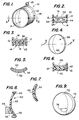
- Figure 1 is a perspective view of a mold of the invention.
- Figure 2 is a cross-section of the embodiment shown in Figure 1 taken along lines 2-2.
- Figure 3 is the cross-section shown in Figure 2 including material to be molded.
- Figure 4 is a perspective view of the lens formed using the apparatus of Figure 1.
- Figure 5 is a cross-section of the lens as shown in Figure 4 taken along lines 5-5.
- Figure 6 is a cross-section of a mold utilizing another process of the invention.
- Figure 7 is a cross-section of the lens formed by the apparatus shown in Figure 6.
- Figure 8 is a cross-section of another embodiment of the invention showing a segment mold.
- Figure 9 is a perspective view of the lens with a bifocal segment formed by the process as shown in Figure 8.
- The mold for producing tinted lens and lens with other configurations is shown in Figure 1. Mold 10 includes a
flexible gasket 12 in the form of a band which completely circumscribes other elements of the mold. The mold includes afront form 14 and arear form 16 releasably secured in sealing relationship with respect to the gasket. These first and second mold forms 14 and 16 are spaced from one another to formcavity 28 therebetween. Eachmold form - As can be seen more clearly in Figure 3, the
first form 14 includes aconvex surface 26 exterior exposed to the exterior of the mold and a concave surface 24 facing the interior of themold cavity 28. The second mold form, orrear mold 16, includes an interior convex surface 20 and an exteriorconcave surface 22. For the purposes of defining the form of the lens, the interior surfaces 24 and 20 will impart to the lens the desired form to achieve the prescribed correction. Theexterior surfaces annular grooves mold cavity 28 for forming the lens. As shown in Figure 2, the front and rear mold forms are made of glass. However, they could be made of metal so long as they have the desired configuration and interact with the gasket as described above. - Utilizing this mold, a process for achieving tinting of the lens can be achieved eliminating gradients and other problems discussed above. The tinting is achieved by utilizing a pre-tinted plastic wafer inserted into the mold between liquid monomer molding material as can be seen in Figure 3. The process steps include initially placing the first or
front mold form 14 into thegasket 12 as shown. The liquid monomer, or at least a portion of the liquid monomer is placed into themold form 14 and thewafer 33 is then placed in contiguous relationship with the liquid monomer before the mold is closed. The mold is then closed by placing rear orsecond mold form 16 into sealing relationship with the gasket, as shown in Figure 3. This will leave acavity 28 in the mold between thesecond mold form 16 and thewafer 33.Cavity 28 is then filled with liquid monomer to completely fill all the voids within the cavity. - The mold with the
liquid monomer wafer 33 therebetween is then subjected to oven-curing for polymerizing the liquid monomer. During this curing, the liquid monomer solidifies and causes an intermolecular bonding with thewafer material 33. In this specific embodiment, the wafer material is formed from the same monomer as the liquid monomer used in the molding process. Once the curing step has been completed, the mold is removed from the oven and the mold forms peeled away from the gasket permitting thelens 36 to be removed.Lens 36 as shown in Figure 4 and in a cross-section in Figure 5. There it can be seen that the tinted wafer remains tinted at a relatively constant cross-section in the vicinity of the wafer as originally placed during the molding process bounded on either side by the polymerizedplastic material - Although in the drawing, definite lines of demarcation between the
wafer 33 and the plastic material bounding it on eitherside - The type of plastic material used in the preferred embodiment is CR-39 which is a registered trademark of PPG Industries and a form of allyl diglycol carbonate. The wafer is initially formed in prior molding process from the monomer and polymerized to form a solid plastic material in a disc-like configuration. This wafer is then tinted to the desired color by subjecting it to a bath of dye until the desired tint is achieved. The hard or cured wafer is then used in the liquid monomer as discussed above to achieve the desired tint. After this process, of course, the lens can be subjected to other processes such as hard coating or other finishes as may be desired without adversely affecting the tint. Because the tint is completely interior to the portion of the lens, it is generally not subject to any surface abrasions.
- In addition to carrying tint, the wafer can also act as a carrier for other materials. Often, for cosmetic reasons, it is desirable to have jewelry or inscription embodied in the wafer and ultimately on the glasses. This is achieved simply by using adhesive and to adhere the jewelry or other material for example that which can be used to form the initials of the patient in securing this matter to the carrier. The carrier can then be placed into the mold as described above, and once the molding process is completed, the jewelry or other cosmetic material will be retained within the plastic mold and not subjected to scratching or other abrasives which could otherwise cause these cosmetic items to be damaged or even removed from the lens.
- In another embodiment of the invention, the first form as can be seen in Figure 6,
form 40, is made of plastic material and actually forms part of the ultimately formed lens. In this process it is essential that theform 40 have an exterior surface 41 which is configured to cooperate with other portions of the lens and achieve the desired power and correction. Thesecond form 46 acts in the same manner asform 16 described above in defining an interior convex surface corresponding to the concave surface of the lens being formed. - Where tinting is desired,
form 40 is subjected to the tinting process as discussed above with respect to thewafer 33. Becauseform 40 will have a consistent cross-sectional area throughout, it still would not be subjected to the gradient problems which would otherwise occur in tinting the ultimately formed lens. However, to insure that any abrasion or scratching of the exterior surface adversely affects the tint, it can be hard-coated prior to subjecting it to a molding process. - In any event, once the
form 40 has been tinted, it is fixed to gasket 12 as shown. The rear orsecond mold form 46 is also secured to the gasket spaced from thefirst form 40 to form a cavity therebetween in sealed relationship withgasket 12. Once the forms are in place, the liquid monomer is delivered to the cavity in the same manner discussed above with respect to Figure 1. Again, the mold is subjected to oven curing until the monomer is polymerized and sufficiently hardened to act as a lens for glasses. Once the curing process is completed, the mold is removed and the lens extracted from the mold. However, in this instance, the mold form will ultimately form part of the lens and therefore theform 40 can be referred to as "consumed during the molding process. As can be seen in Figure 7,mold form 40 is bonded to theportion 42 formed during the molding process. Again, as with Figure 5, although clear line of delineation are shown between theseitems - In another embodiment of the invention, the
wafer 33 shown in Figure 3, could be in the form of a bifocal or other multifocal lens. In this instance, the bifocal segment of the wafer would be formed prior to its use in the mold with the bifocal or multifocal segments having the desired power or correction. Because the plastic material during the molding process will completely engulf the segment and can possibly detract from the corrective features, the wafer is formed from material having a different index of refraction than that of the molding material. This insures that the bifocal or multifocal features are not changed during the molding process. The process of placing the wafer into the mold is accomplished in the same manner as described in conjunction with Figure 3 and is not required to be reiterated here. - As with the tinted process, the wafer with the bifocal or multifocal features can also form the exterior portion of the form as described above with respect to Figures 6 and 7. In this embodiment, again, the wafer would be preformed having the desired multifocal segments formed thereon. The wafer can then be fixed in place as shown in Figure 6 and formed by delivering the liquid monomer to the cavity, subjecting it to curing until sufficiently hardened, and remove it from the cavity as discussed above. In this case, since
form 40 employs a bifocal segment on its exterior surface, it can be of the same material as the liquid monomer. - It should be understood that, although the above invention has been discussed largely with configuration of the first or front mold form, particularly with respect to consumable molds, the rear mold can have the desired configuration and other features. This may be more advantageous particularly with bifocal lens since the bifocal or multifocal segments would be in the rear portion of the lens and not extending from the front surface which might create an unacceptable appearance to the consumer.
- Another feature of the invention is to insure that the multifocal segments are placed in the correct position with regard to the wearer. In certain performance lenses, the bifocal or multifocal segments may not be in a position which is comfortable to the patient. To avoid this problem, where the lens is formed by one of the processes noted above, the bifocal segment can be added in a subsequent molding process. As can be seen in Figure 8, a
segment mold 54 is fixed to the desired position on the front of thelens 52. This mold will form acavity 56 sealed from the surrounding environment between the mold and the lens. Thiscavity 56 configuration corresponds to the desired correction or power for the lens. The liquid monomer is delivered to the cavity until it completely fills all the voids therein and the lens is then treated in the same manner as discussed above with regard to oven curing to insure that its polymerization occurs and sufficiently hardening occurs. Thelens 70 includes thebifocal segment 74 as shown fixed to the surface of the lens by intermolecular bonding during the curing process using the mold described above in conjunction with Figure 8. - In addition to tinting or bifocal features, the wafer can include polarizing features such that the desired polarity is achieved and is completely sealed from the surrounding environment by the molded plastic. Photochromatic material can be used in conjunction with the wafer and molded according to the processes discussed above. To achieve the desired photochromatic features, typically the photochromatic material would operate in conjunction with other tinted material on the surface of the lens. It has often been difficult to achieve photochromatic features in a fully plasticized lens. When the photochromatic material is used in conjunction with other tinted material as discussed above, it will cooperate with the tint to achieve the desired overall color and shading when subjected to light.
- In another embodiment of the invention one portion of the lens being molded can be of a softer material than another. For example, where a first mold form is part of a consummable mold, it can be cured such that it will not harden to the degree of other portions of material and prism the lens. Where the consummable mold form is hard-coated, then subjected to the molding process discussed above, the plastic material of the mold form will be softer and relatively resilient. This enables the lens to better avoid shattering and accept shock. The same effect is accomplished where the wafer that is used as an intermediate in the molding process is of a softer material than the surrounding plastic.
- The above has been a detailed discussion of the preferred embodiment. It should not be considered undue limiting of applicant's invention which is more fully defined in the claims which follow.
Claims (14)
a first mould form having a concave portion;
a second mould form, e.g. comprising glass or metal, having a convex portion;
a flexible gasket member having an annular configuration and including means for receiving the first and second mould form each in sealing relationship therewith and spaced apart to form a cavity therebetween, to define a mould having convex and concave portions, and in which a lens having respectively concave and convex portions can be formed; and
means for permitting access to the cavity for the delivery of liquid plastic moulding material thereto;
in combination with a wafer of solid plastic material which preferably has an effective diameter substantially identical to that of the mould forms.
Applications Claiming Priority (2)
| Application Number | Priority Date | Filing Date | Title |
|---|---|---|---|
| US07/114,962 US4873029A (en) | 1987-10-30 | 1987-10-30 | Method for manufacturing lenses |
| US114962 | 1987-10-30 |
Publications (2)
| Publication Number | Publication Date |
|---|---|
| EP0314417A2 true EP0314417A2 (en) | 1989-05-03 |
| EP0314417A3 EP0314417A3 (en) | 1990-04-04 |
Family
ID=22358530
Family Applications (1)
| Application Number | Title | Priority Date | Filing Date |
|---|---|---|---|
| EP88309979A Withdrawn EP0314417A3 (en) | 1987-10-30 | 1988-10-24 | Method and apparatus for manufacturing lenses |
Country Status (3)
| Country | Link |
|---|---|
| US (1) | US4873029A (en) |
| EP (1) | EP0314417A3 (en) |
| JP (1) | JP2542061B2 (en) |
Cited By (8)
| Publication number | Priority date | Publication date | Assignee | Title |
|---|---|---|---|---|
| WO1991008105A2 (en) * | 1989-12-05 | 1991-06-13 | Blum Ronald D | Method for forming plastic optical quality spectacle lenses |
| EP0457855A1 (en) * | 1989-12-05 | 1991-11-27 | Vision Science, Inc. | Method for forming plastic optical quality spectacle |
| US5178800A (en) * | 1990-10-10 | 1993-01-12 | Innotech, Inc. | Method for forming plastic optical quality spectacle lenses |
| WO1994004344A1 (en) * | 1992-08-18 | 1994-03-03 | Q2100, Inc. | Progressive lens apparatus and process |
| US5989462A (en) * | 1997-07-31 | 1999-11-23 | Q2100, Inc. | Method and composition for producing ultraviolent blocking lenses |
| US6086799A (en) * | 1996-04-19 | 2000-07-11 | Q2100, Inc. | Methods and apparatus for eyeglass lens curing using ultraviolet light and improved cooling |
| US6228289B1 (en) | 1998-09-25 | 2001-05-08 | Q2100, Inc. | Plastic lens systems and methods |
| US6494702B1 (en) | 1986-01-28 | 2002-12-17 | Q2100, Inc. | Apparatus for the production of plastic lenses |
Families Citing this family (151)
| Publication number | Priority date | Publication date | Assignee | Title |
|---|---|---|---|---|
| US6730244B1 (en) | 1986-01-28 | 2004-05-04 | Q2100, Inc. | Plastic lens and method for the production thereof |
| US5529728A (en) | 1986-01-28 | 1996-06-25 | Q2100, Inc. | Process for lens curing and coating |
| US6201037B1 (en) | 1986-01-28 | 2001-03-13 | Ophthalmic Research Group International, Inc. | Plastic lens composition and method for the production thereof |
| US5364256A (en) | 1986-01-28 | 1994-11-15 | Ophthalmic Research Group International, Inc. | Apparatus for the production of plastic lenses |
| US5219497A (en) * | 1987-10-30 | 1993-06-15 | Innotech, Inc. | Method for manufacturing lenses using thin coatings |
| US5147585A (en) * | 1987-10-30 | 1992-09-15 | Blum Ronald D | Method for forming plastic optical quality spectacle lenses |
| US5880171A (en) * | 1989-05-01 | 1999-03-09 | 2C Optics, Inc. | Fast curing polymeric compositions for ophthalmic lenses and apparatus for preparing lenses |
| US5114632A (en) * | 1989-05-01 | 1992-05-19 | Soane Technologies, Inc. | Controlled casting of a shrinkable material |
| US5232637A (en) * | 1992-01-21 | 1993-08-03 | Corning Incorporated | Ophthalmic lens method |
| US5286419A (en) * | 1992-02-20 | 1994-02-15 | Bmc Industries, Inc. | Process for making a light polarizing spectacle lens |
| US5470892A (en) * | 1992-05-01 | 1995-11-28 | Innotech, Inc. | Polymerizable resin for forming clear, hard plastics |
| US5405557A (en) * | 1993-04-21 | 1995-04-11 | Sola Group Ltd. | Method of making a moulded photochromic lens |
| US5422046A (en) * | 1993-08-31 | 1995-06-06 | Essilor Of America, Inc. | Method for producing optical lenses |
| US5514214A (en) | 1993-09-20 | 1996-05-07 | Q2100, Inc. | Eyeglass lens and mold spin coater |
| US5757459A (en) * | 1995-03-03 | 1998-05-26 | Vision-Ease Lens, Inc. | Multifocal optical elements |
| US7048997B2 (en) * | 1995-03-03 | 2006-05-23 | Vision-Ease Lens | Production of optical elements |
| US5861934A (en) * | 1996-05-06 | 1999-01-19 | Innotech, Inc. | Refractive index gradient lens |
| US6280171B1 (en) | 1996-06-14 | 2001-08-28 | Q2100, Inc. | El apparatus for eyeglass lens curing using ultraviolet light |
| US5793465A (en) * | 1996-10-08 | 1998-08-11 | Innotech, Inc. | Toric surfacecasting |
| US6025026A (en) * | 1997-06-30 | 2000-02-15 | Transitions Optical, Inc. | Process for producing an adherent polymeric layer on polymeric substrates and articles produced thereby |
| US6089710A (en) | 1998-07-20 | 2000-07-18 | Oracle Lens Manufacturing Corporation | Single-vision ophthalmic lens series |
| WO2000005060A1 (en) * | 1998-07-24 | 2000-02-03 | Optical Molding Systems, Inc. | Method and compositions for manufacturing coated photochromatic articles |
| US6936197B1 (en) | 1998-07-24 | 2005-08-30 | Duane L. Wires | Method and compositions for manufacturing coated photochromatic articles |
| US6391231B1 (en) | 1998-11-23 | 2002-05-21 | Younger Mfg. Co. | Method for side-fill lens casting |
| US7002744B2 (en) * | 1999-11-22 | 2006-02-21 | Younger Mfg. Co. Dba Younger Optics | Polarized optical part using high impact polyurethane-based material |
| US6436525B1 (en) | 1998-12-11 | 2002-08-20 | Ppg Industries Ohio, Inc. | Polyanhydride photochromic coating composition and photochromic articles |
| US6060001A (en) * | 1998-12-14 | 2000-05-09 | Ppg Industries Ohio, Inc. | Alkoxyacrylamide photochromic coatings compositions and photochromic articles |
| US6432544B1 (en) | 1998-12-18 | 2002-08-13 | Ppg Industries Ohio, Inc. | Aminoplast resin photochromic coating composition and photochromic articles |
| US6506488B1 (en) | 1998-12-18 | 2003-01-14 | Ppg Industries Ohio, Inc. | Aminoplast resin photochromic coating composition and photochromic articles |
| US6419873B1 (en) | 1999-03-19 | 2002-07-16 | Q2100, Inc. | Plastic lens systems, compositions, and methods |
| FR2793038B1 (en) | 1999-04-29 | 2002-01-25 | Essilor Int | COMPOSITE OPHTHALMIC LENS AND METHOD FOR OBTAINING SUCH A LENS |
| US7023594B2 (en) | 2000-06-23 | 2006-04-04 | E-Vision, Llc | Electro-optic lens with integrated components |
| US6619799B1 (en) | 1999-07-02 | 2003-09-16 | E-Vision, Llc | Optical lens system with electro-active lens having alterably different focal lengths |
| US7775660B2 (en) | 1999-07-02 | 2010-08-17 | E-Vision Llc | Electro-active ophthalmic lens having an optical power blending region |
| US6231183B1 (en) | 1999-07-06 | 2001-05-15 | Stephen M. Dillon | Optical lens structure and method of fabrication thereof |
| US6348604B1 (en) | 1999-09-17 | 2002-02-19 | Ppg Industries Ohio, Inc. | Photochromic naphthopyrans |
| US6296785B1 (en) | 1999-09-17 | 2001-10-02 | Ppg Industries Ohio, Inc. | Indeno-fused photochromic naphthopyrans |
| US6432327B2 (en) | 1999-12-29 | 2002-08-13 | Younger Mfg. Co. | Formed polyethylene terephthalate polarizing film for incorporation in optical-grade plastic parts |
| US6220703B1 (en) | 1999-12-29 | 2001-04-24 | Younger Manufacturing Co., Inc. | Ophthalmic lenses utilizing polyethylene terephthalate polarizing films |
| US6759090B2 (en) * | 1999-12-29 | 2004-07-06 | Younger Mfg. Co. | Method for improved adhesion of an optical coating to a polarizing film |
| US6716375B1 (en) | 2000-03-30 | 2004-04-06 | Q2100, Inc. | Apparatus and method for heating a polymerizable composition |
| US6698708B1 (en) | 2000-03-30 | 2004-03-02 | Q2100, Inc. | Gasket and mold assembly for producing plastic lenses |
| US6723260B1 (en) | 2000-03-30 | 2004-04-20 | Q2100, Inc. | Method for marking a plastic eyeglass lens using a mold assembly holder |
| US7077985B2 (en) | 2000-05-30 | 2006-07-18 | Vision-Ease Lens | Injection molding of lens |
| US6632535B1 (en) | 2000-06-08 | 2003-10-14 | Q2100, Inc. | Method of forming antireflective coatings |
| US6638450B2 (en) | 2000-11-02 | 2003-10-28 | Vtec Technologies, Inc. | Method for manufacturing an injection molded thermoplastic ophthalmic lens having an encapsulated light polarizing element |
| US6808381B2 (en) | 2001-02-20 | 2004-10-26 | Q2100, Inc. | Apparatus for preparing an eyeglass lens having a controller |
| US6726463B2 (en) | 2001-02-20 | 2004-04-27 | Q2100, Inc. | Apparatus for preparing an eyeglass lens having a dual computer system controller |
| US6790024B2 (en) | 2001-02-20 | 2004-09-14 | Q2100, Inc. | Apparatus for preparing an eyeglass lens having multiple conveyor systems |
| US6752613B2 (en) | 2001-02-20 | 2004-06-22 | Q2100, Inc. | Apparatus for preparing an eyeglass lens having a controller for initiation of lens curing |
| US6758663B2 (en) | 2001-02-20 | 2004-07-06 | Q2100, Inc. | System for preparing eyeglass lenses with a high volume curing unit |
| US6676399B1 (en) | 2001-02-20 | 2004-01-13 | Q2100, Inc. | Apparatus for preparing an eyeglass lens having sensors for tracking mold assemblies |
| US6790022B1 (en) | 2001-02-20 | 2004-09-14 | Q2100, Inc. | Apparatus for preparing an eyeglass lens having a movable lamp mount |
| US6712331B2 (en) | 2001-02-20 | 2004-03-30 | Q2100, Inc. | Holder for mold assemblies with indicia |
| US6676398B2 (en) | 2001-02-20 | 2004-01-13 | Q2100, Inc. | Apparatus for preparing an eyeglass lens having a prescription reader |
| US6655946B2 (en) | 2001-02-20 | 2003-12-02 | Q2100, Inc. | Apparatus for preparing an eyeglass lens having a controller for conveyor and curing units |
| US6709257B2 (en) | 2001-02-20 | 2004-03-23 | Q2100, Inc. | Eyeglass lens forming apparatus with sensor |
| US6612828B2 (en) | 2001-02-20 | 2003-09-02 | Q2100, Inc. | Fill system with controller for monitoring use |
| US6702564B2 (en) | 2001-02-20 | 2004-03-09 | Q2100, Inc. | System for preparing an eyeglass lens using colored mold holders |
| FR2828743B1 (en) * | 2001-08-14 | 2004-02-27 | Essilor Int | METHOD FOR MOLDING A LENS HAVING AN INSERT |
| US7410691B2 (en) * | 2001-12-27 | 2008-08-12 | Ppg Industries Ohio, Inc. | Photochromic optical article |
| US7452611B2 (en) * | 2001-12-27 | 2008-11-18 | Transitions Optical, Inc. | Photochromic optical article |
| US6464484B1 (en) | 2002-03-30 | 2002-10-15 | Q2100, Inc. | Apparatus and system for the production of plastic lenses |
| WO2003098971A1 (en) | 2002-05-13 | 2003-11-27 | S.C. Johnson & Son, Inc. | Coordinated emission of fragrance, light, and sound |
| JP4225970B2 (en) * | 2002-05-27 | 2009-02-18 | 株式会社トクヤマ | Method for producing laminate having photochromic properties |
| US7465414B2 (en) * | 2002-11-14 | 2008-12-16 | Transitions Optical, Inc. | Photochromic article |
| MXPA05008369A (en) | 2003-02-07 | 2005-11-04 | Johnson & Son Inc S C | Diffuser with light emitting diode nightlight. |
| US7262295B2 (en) | 2003-03-20 | 2007-08-28 | Transitions Optical, Inc. | Indeno-fused photochromic naphthopyrans, naphthols and photochromic articles |
| US6926405B2 (en) * | 2003-06-06 | 2005-08-09 | Younger Mfg. Co. | Eyewear lens having selective spectral response |
| US20110140056A1 (en) * | 2003-07-01 | 2011-06-16 | Transitions Optical, Inc. | Indeno-fused ring compounds |
| US8545984B2 (en) * | 2003-07-01 | 2013-10-01 | Transitions Optical, Inc. | Photochromic compounds and compositions |
| US8518546B2 (en) * | 2003-07-01 | 2013-08-27 | Transitions Optical, Inc. | Photochromic compounds and compositions |
| US8698117B2 (en) | 2003-07-01 | 2014-04-15 | Transitions Optical, Inc. | Indeno-fused ring compounds |
| US7342112B2 (en) * | 2003-07-01 | 2008-03-11 | Ppg Industries Ohio, Inc. | Photochromic compounds |
| US8545015B2 (en) | 2003-07-01 | 2013-10-01 | Transitions Optical, Inc. | Polarizing photochromic articles |
| US7978391B2 (en) * | 2004-05-17 | 2011-07-12 | Transitions Optical, Inc. | Polarizing, photochromic devices and methods of making the same |
| US7632540B2 (en) | 2003-07-01 | 2009-12-15 | Transitions Optical, Inc. | Alignment facilities for optical dyes |
| US8582192B2 (en) | 2003-07-01 | 2013-11-12 | Transitions Optical, Inc. | Polarizing photochromic articles |
| US8211338B2 (en) | 2003-07-01 | 2012-07-03 | Transitions Optical, Inc | Photochromic compounds |
| US9096014B2 (en) | 2003-07-01 | 2015-08-04 | Transitions Optical, Inc. | Oriented polymeric sheets exhibiting dichroism and articles containing the same |
| US8089678B2 (en) | 2003-07-01 | 2012-01-03 | Transitions Optical, Inc | Clear to circular polarizing photochromic devices and methods of making the same |
| US7256921B2 (en) | 2003-07-01 | 2007-08-14 | Transitions Optical, Inc. | Polarizing, photochromic devices and methods of making the same |
| WO2005016617A1 (en) * | 2003-08-19 | 2005-02-24 | Menicon Co., Ltd. | Process for producing contact lens with marking and contact lens with marking obtained thereby |
| US7858001B2 (en) | 2003-09-09 | 2010-12-28 | Insight Equity A.P.X., L.P. | Photochromic lens |
| EP1673655B1 (en) | 2003-09-09 | 2015-05-06 | Insight Equity A.P.X., LP | Photochromic polyurethane laminate |
| US20050104240A1 (en) * | 2003-11-14 | 2005-05-19 | Jethmalani Jagdish M. | Method of manufacturing an optical lens |
| US7094368B2 (en) * | 2003-12-10 | 2006-08-22 | Transitions Optical, Inc. | Pyrano-quinolines, pyrano-quinolinones, combinations thereof, photochromic compositions and articles |
| US7097303B2 (en) * | 2004-01-14 | 2006-08-29 | Ppg Industries Ohio, Inc. | Polarizing devices and methods of making the same |
| US20050196616A1 (en) * | 2004-03-04 | 2005-09-08 | Stewart Kevin J. | Photochromic optical article |
| US7144966B2 (en) * | 2004-03-04 | 2006-12-05 | Basf Corporation | Acrylic composition for use in coating applications and a method of forming the same |
| US7189456B2 (en) * | 2004-03-04 | 2007-03-13 | Transitions Optical, Inc. | Photochromic optical article |
| US7811480B2 (en) * | 2004-03-04 | 2010-10-12 | Transitions Optical, Inc. | Photochromic optical article |
| US20050196626A1 (en) * | 2004-03-04 | 2005-09-08 | Knox Carol L. | Photochromic optical article |
| US7261843B2 (en) * | 2004-03-04 | 2007-08-28 | Transitions Optical, Inc. | Photochromic optical article |
| US8915588B2 (en) | 2004-11-02 | 2014-12-23 | E-Vision Smart Optics, Inc. | Eyewear including a heads up display |
| US9801709B2 (en) | 2004-11-02 | 2017-10-31 | E-Vision Smart Optics, Inc. | Electro-active intraocular lenses |
| US8778022B2 (en) | 2004-11-02 | 2014-07-15 | E-Vision Smart Optics Inc. | Electro-active intraocular lenses |
| US20060103041A1 (en) * | 2004-11-18 | 2006-05-18 | Kai Su | Molds and method of using the same for forming plus or minus lenses |
| US8899547B2 (en) | 2004-11-18 | 2014-12-02 | Qspex Technologies, Inc. | Molds and method of using the same for optical lenses |
| US20060103037A1 (en) * | 2004-11-18 | 2006-05-18 | Kai Su | Disposable molds and method of using the same |
| US8002935B2 (en) | 2005-03-04 | 2011-08-23 | Insight Equity A.P.X., L.P. | Forming method for polymeric laminated wafers comprising different film materials |
| US7281811B2 (en) | 2005-03-31 | 2007-10-16 | S. C. Johnson & Son, Inc. | Multi-clarity lenses |
| US7643734B2 (en) | 2005-03-31 | 2010-01-05 | S.C. Johnson & Son, Inc. | Bottle eject mechanism |
| US7589340B2 (en) | 2005-03-31 | 2009-09-15 | S.C. Johnson & Son, Inc. | System for detecting a container or contents of the container |
| US7258437B2 (en) * | 2005-09-07 | 2007-08-21 | Transitions Optical, Inc. | Photochromic multifocal optical article |
| US7443608B2 (en) * | 2006-08-07 | 2008-10-28 | Dillon Stephen M | Uniform diffuse omni-directional reflecting lens |
| AR064985A1 (en) | 2007-01-22 | 2009-05-06 | E Vision Llc | FLEXIBLE ELECTROACTIVE LENS |
| AU2008218240B2 (en) | 2007-02-23 | 2014-01-30 | E-Vision Smart Optics, Inc. | Ophthalmic dynamic aperture |
| US7926940B2 (en) | 2007-02-23 | 2011-04-19 | Pixeloptics, Inc. | Advanced electro-active optic device |
| US7883206B2 (en) | 2007-03-07 | 2011-02-08 | Pixeloptics, Inc. | Multifocal lens having a progressive optical power region and a discontinuity |
| US20080273169A1 (en) | 2007-03-29 | 2008-11-06 | Blum Ronald D | Multifocal Lens Having a Progressive Optical Power Region and a Discontinuity |
| US7883207B2 (en) | 2007-12-14 | 2011-02-08 | Pixeloptics, Inc. | Refractive-diffractive multifocal lens |
| US10613355B2 (en) | 2007-05-04 | 2020-04-07 | E-Vision, Llc | Moisture-resistant eye wear |
| US11061252B2 (en) | 2007-05-04 | 2021-07-13 | E-Vision, Llc | Hinge for electronic spectacles |
| ES2550756T3 (en) * | 2007-09-24 | 2015-11-12 | Qspex Technologies, Inc. | Method for manufacturing polarized ophthalmic lenses |
| US7926941B2 (en) * | 2007-12-14 | 2011-04-19 | Pixeloptics Inc. | Multiple layer multifocal composite lens |
| US7744215B2 (en) * | 2007-12-25 | 2010-06-29 | Pixeloptics, Inc. | Multiple layer multifocal composite lens |
| US8154804B2 (en) | 2008-03-25 | 2012-04-10 | E-Vision Smart Optics, Inc. | Electro-optic lenses for correction of higher order aberrations |
| US9296158B2 (en) | 2008-09-22 | 2016-03-29 | Johnson & Johnson Vision Care, Inc. | Binder of energized components in an ophthalmic lens |
| US9675443B2 (en) | 2009-09-10 | 2017-06-13 | Johnson & Johnson Vision Care, Inc. | Energized ophthalmic lens including stacked integrated components |
| US20100078837A1 (en) * | 2008-09-29 | 2010-04-01 | Pugh Randall B | Apparatus and method for formation of an energized ophthalmic device |
| US8348424B2 (en) | 2008-09-30 | 2013-01-08 | Johnson & Johnson Vision Care, Inc. | Variable focus ophthalmic device |
| JP2010281964A (en) * | 2009-06-03 | 2010-12-16 | Nidek Co Ltd | Method of producing dyed optical component and dyed semi-finish lens |
| US8608988B2 (en) | 2010-11-23 | 2013-12-17 | Transitions Optical, Inc. | Curable photochromic compositions and optical articles prepared therefrom |
| US8950862B2 (en) | 2011-02-28 | 2015-02-10 | Johnson & Johnson Vision Care, Inc. | Methods and apparatus for an ophthalmic lens with functional insert layers |
| US9698129B2 (en) | 2011-03-18 | 2017-07-04 | Johnson & Johnson Vision Care, Inc. | Stacked integrated component devices with energization |
| US10451897B2 (en) | 2011-03-18 | 2019-10-22 | Johnson & Johnson Vision Care, Inc. | Components with multiple energization elements for biomedical devices |
| US9889615B2 (en) | 2011-03-18 | 2018-02-13 | Johnson & Johnson Vision Care, Inc. | Stacked integrated component media insert for an ophthalmic device |
| US9804418B2 (en) | 2011-03-21 | 2017-10-31 | Johnson & Johnson Vision Care, Inc. | Methods and apparatus for functional insert with power layer |
| KR102276220B1 (en) | 2012-01-06 | 2021-07-13 | 이-비전 스마트 옵틱스, 아이엔씨. | Eyewear docking station and electronic module |
| US8857983B2 (en) | 2012-01-26 | 2014-10-14 | Johnson & Johnson Vision Care, Inc. | Ophthalmic lens assembly having an integrated antenna structure |
| CA2862665A1 (en) | 2012-01-26 | 2013-08-01 | Johnson & Johnson Vision Care, Inc. | Energized ophthalmic lens including stacked integrated components |
| US9244201B2 (en) | 2012-04-14 | 2016-01-26 | Stephen M. Dillon | Diffuse reflecting optical construction |
| ITPD20130209A1 (en) * | 2013-07-26 | 2015-01-27 | Safilo Spa | METHOD OF MANUFACTURING A POLARIZED LENS FOR GLASSES AND LENSES MADE WITH A CALLED METHOD |
| US9933632B2 (en) | 2014-03-26 | 2018-04-03 | Indizen Optical Technologies, S.L. | Eyewear lens production by multi-layer additive techniques |
| US9952448B2 (en) | 2014-03-26 | 2018-04-24 | Indizen Optical Technologies, S.L. | Eyewear lens production by additive techniques |
| US10361404B2 (en) | 2014-08-21 | 2019-07-23 | Johnson & Johnson Vision Care, Inc. | Anodes for use in biocompatible energization elements |
| US10381687B2 (en) | 2014-08-21 | 2019-08-13 | Johnson & Johnson Vision Care, Inc. | Methods of forming biocompatible rechargable energization elements for biomedical devices |
| US10627651B2 (en) | 2014-08-21 | 2020-04-21 | Johnson & Johnson Vision Care, Inc. | Methods and apparatus to form biocompatible energization primary elements for biomedical devices with electroless sealing layers |
| US9715130B2 (en) | 2014-08-21 | 2017-07-25 | Johnson & Johnson Vision Care, Inc. | Methods and apparatus to form separators for biocompatible energization elements for biomedical devices |
| US9599842B2 (en) | 2014-08-21 | 2017-03-21 | Johnson & Johnson Vision Care, Inc. | Device and methods for sealing and encapsulation for biocompatible energization elements |
| US9793536B2 (en) | 2014-08-21 | 2017-10-17 | Johnson & Johnson Vision Care, Inc. | Pellet form cathode for use in a biocompatible battery |
| US10361405B2 (en) | 2014-08-21 | 2019-07-23 | Johnson & Johnson Vision Care, Inc. | Biomedical energization elements with polymer electrolytes |
| US9383593B2 (en) | 2014-08-21 | 2016-07-05 | Johnson & Johnson Vision Care, Inc. | Methods to form biocompatible energization elements for biomedical devices comprising laminates and placed separators |
| CN107924116B (en) | 2015-09-03 | 2021-06-15 | 光学转变公司 | Multilayer photochromic articles |
| US10345620B2 (en) | 2016-02-18 | 2019-07-09 | Johnson & Johnson Vision Care, Inc. | Methods and apparatus to form biocompatible energization elements incorporating fuel cells for biomedical devices |
| US10599006B2 (en) | 2016-04-12 | 2020-03-24 | E-Vision Smart Optics, Inc. | Electro-active lenses with raised resistive bridges |
| ES2861520T3 (en) | 2016-04-12 | 2021-10-06 | E Vision Smart Optics Inc | Electroactive lenses with high resistive bridges |
| US10698139B2 (en) | 2016-10-03 | 2020-06-30 | Stephen M. Dillon | Diffuse reflecting optical construction |
| US10866455B2 (en) | 2017-10-19 | 2020-12-15 | Ppg Industries Ohio, Inc. | Display devices including photochromic-dichroic compounds and dichroic compounds |
| EP3763517A1 (en) | 2019-07-09 | 2021-01-13 | Essilor International | Method for manufacturing a photochromic optical article |
Citations (10)
| Publication number | Priority date | Publication date | Assignee | Title |
|---|---|---|---|---|
| FR1522002A (en) * | 1967-05-05 | 1968-04-19 | Kirk Optical Lens Co | transparent element such as a lens or a mirror and method for its production |
| US3649236A (en) * | 1970-03-05 | 1972-03-14 | Bausch & Lomb | Manufacture of multifocal ophthalmic lens molds |
| US3771858A (en) * | 1972-01-31 | 1973-11-13 | C Bivens | Ophthalmic lens |
| GB1347762A (en) * | 1971-04-15 | 1974-02-27 | Polaroid Corp | Opthalmic lenses and method for their manufacture |
| FR2450469A1 (en) * | 1979-02-28 | 1980-09-26 | Essilor Int | PHOTOCHROMIC OPHTHALMIC LENS IN ORGANIC MATTER |
| US4245896A (en) * | 1978-10-24 | 1981-01-20 | Kaplan Michael A | Spectacles |
| EP0028974A1 (en) * | 1979-11-08 | 1981-05-20 | ESSILOR INTERNATIONAL Compagnie Générale d'Optique | Method of making a composite glass, and composite glass, especially ophthalmic lens, so obtained |
| US4447474A (en) * | 1982-08-30 | 1984-05-08 | Neefe Charles W | Method of selectively tinting soft contact lenses |
| JPS59169820A (en) * | 1983-03-17 | 1984-09-25 | Takashi Imaoka | Manufacture of polarizing lens made of synthetic resin |
| FR2549968A1 (en) * | 1983-07-29 | 1985-02-01 | Suwa Seikosha Kk | LENS OF PLASTIC MATERIAL WITH COATING IN MINERAL MATERIALS |
Family Cites Families (16)
| Publication number | Priority date | Publication date | Assignee | Title |
|---|---|---|---|---|
| US2397231A (en) * | 1941-11-15 | 1946-03-26 | Polaroid Corp | Process of manufacturing coated light polarizers |
| GB699736A (en) * | 1949-03-14 | 1953-11-18 | Mueller Welt G M B H | Improvements in and relating to the manner of manufacture of contact lenses |
| DE882004C (en) * | 1951-06-21 | 1953-07-06 | Mueller Welt G M B H | Process for the production of adhesive glasses from transparent organic plastic |
| US3674587A (en) * | 1970-05-06 | 1972-07-04 | American Optical Corp | Producing polarizing optical devices and product thereof |
| US3711417A (en) * | 1970-07-01 | 1973-01-16 | Polaroid Corp | Multilayer light polarizing lens |
| FR2118305A5 (en) * | 1970-12-14 | 1972-07-28 | Vergo Sa | |
| JPS5513009B2 (en) * | 1972-05-02 | 1980-04-05 | ||
| US3940304A (en) * | 1972-05-02 | 1976-02-24 | Polaroid Corporation | Method of making composite light-polarizing element |
| US4320940A (en) * | 1978-06-19 | 1982-03-23 | Mueller Gary E | Optical filtering element |
| JPS57110431A (en) * | 1980-12-29 | 1982-07-09 | Komaki Kagaku Gijutsu Sogo Kenkyusho:Kk | Decorative product and preparation thereof |
| US4498883A (en) * | 1981-10-05 | 1985-02-12 | Gte Products Corporation | Method of encapsulating a photoflash lamp using a powdered resin |
| JPS61173910A (en) * | 1985-01-30 | 1986-08-05 | Seiko Epson Corp | Laminated photochromic lens |
| JPS61213114A (en) * | 1985-03-19 | 1986-09-22 | Asahi Glass Co Ltd | Manufacture of composite plastics |
| JPS61236521A (en) * | 1985-04-12 | 1986-10-21 | Kureha Chem Ind Co Ltd | Light controlling lens and its production |
| JPS61235113A (en) * | 1985-04-12 | 1986-10-20 | Asahi Glass Co Ltd | Manufacture of composite plastic |
| JPS6218225A (en) * | 1985-07-16 | 1987-01-27 | Mikasa Kogyo Kk | Manufacture of composite lens made of synthetic resin and its gasket for manufacture |
-
1987
- 1987-10-30 US US07/114,962 patent/US4873029A/en not_active Expired - Lifetime
-
1988
- 1988-10-24 EP EP88309979A patent/EP0314417A3/en not_active Withdrawn
- 1988-10-28 JP JP63271059A patent/JP2542061B2/en not_active Expired - Fee Related
Patent Citations (10)
| Publication number | Priority date | Publication date | Assignee | Title |
|---|---|---|---|---|
| FR1522002A (en) * | 1967-05-05 | 1968-04-19 | Kirk Optical Lens Co | transparent element such as a lens or a mirror and method for its production |
| US3649236A (en) * | 1970-03-05 | 1972-03-14 | Bausch & Lomb | Manufacture of multifocal ophthalmic lens molds |
| GB1347762A (en) * | 1971-04-15 | 1974-02-27 | Polaroid Corp | Opthalmic lenses and method for their manufacture |
| US3771858A (en) * | 1972-01-31 | 1973-11-13 | C Bivens | Ophthalmic lens |
| US4245896A (en) * | 1978-10-24 | 1981-01-20 | Kaplan Michael A | Spectacles |
| FR2450469A1 (en) * | 1979-02-28 | 1980-09-26 | Essilor Int | PHOTOCHROMIC OPHTHALMIC LENS IN ORGANIC MATTER |
| EP0028974A1 (en) * | 1979-11-08 | 1981-05-20 | ESSILOR INTERNATIONAL Compagnie Générale d'Optique | Method of making a composite glass, and composite glass, especially ophthalmic lens, so obtained |
| US4447474A (en) * | 1982-08-30 | 1984-05-08 | Neefe Charles W | Method of selectively tinting soft contact lenses |
| JPS59169820A (en) * | 1983-03-17 | 1984-09-25 | Takashi Imaoka | Manufacture of polarizing lens made of synthetic resin |
| FR2549968A1 (en) * | 1983-07-29 | 1985-02-01 | Suwa Seikosha Kk | LENS OF PLASTIC MATERIAL WITH COATING IN MINERAL MATERIALS |
Non-Patent Citations (1)
| Title |
|---|
| PATENT ABSTRACTS OF JAPAN, vol. 9, no. 25 (M-355)[1748], 2nd February 1985; & JP-A-59 169 820 (TAKASHI IMAOKA) 25-09-1984 * |
Cited By (23)
| Publication number | Priority date | Publication date | Assignee | Title |
|---|---|---|---|---|
| US6494702B1 (en) | 1986-01-28 | 2002-12-17 | Q2100, Inc. | Apparatus for the production of plastic lenses |
| WO1991008105A3 (en) * | 1989-12-05 | 1991-07-25 | Ronald D Blum | Method for forming plastic optical quality spectacle lenses |
| EP0457855A1 (en) * | 1989-12-05 | 1991-11-27 | Vision Science, Inc. | Method for forming plastic optical quality spectacle |
| EP0457855A4 (en) * | 1989-12-05 | 1993-07-14 | Vision Science, Inc. | Method for forming plastic optical quality spectacle |
| WO1991008105A2 (en) * | 1989-12-05 | 1991-06-13 | Blum Ronald D | Method for forming plastic optical quality spectacle lenses |
| US5178800A (en) * | 1990-10-10 | 1993-01-12 | Innotech, Inc. | Method for forming plastic optical quality spectacle lenses |
| US5689324A (en) * | 1992-08-18 | 1997-11-18 | Q2100, Inc. | Progressive lens |
| US6105925A (en) * | 1992-08-18 | 2000-08-22 | Q2100, Inc. | Progressive lens apparatus and process |
| WO1994004344A1 (en) * | 1992-08-18 | 1994-03-03 | Q2100, Inc. | Progressive lens apparatus and process |
| US6579478B2 (en) | 1992-08-18 | 2003-06-17 | Q2100, Inc. | Progressive lens apparatus and process |
| US6284159B1 (en) | 1992-08-18 | 2001-09-04 | Q2100, Inc. | Progressive lens apparatus and process |
| US6673278B1 (en) | 1996-04-19 | 2004-01-06 | Q2100, Inc. | Methods and apparatus for eyeglass lens curing using ultraviolet light and improved cooling |
| US6086799A (en) * | 1996-04-19 | 2000-07-11 | Q2100, Inc. | Methods and apparatus for eyeglass lens curing using ultraviolet light and improved cooling |
| US6576167B1 (en) | 1996-04-19 | 2003-06-10 | Q2100, Inc. | Methods and apparatus for eyeglass curing using ultraviolet light and improved cooling |
| US6174155B1 (en) | 1997-07-31 | 2001-01-16 | Q2100, Inc. | Apparatus for producing ultraviolet blocking lenses |
| US6368523B1 (en) | 1997-07-31 | 2002-04-09 | Q2100, Inc. | Method and composition for producing ultraviolet blocking lenses |
| US6367928B1 (en) | 1997-07-31 | 2002-04-09 | Q2100, Inc. | Method and composition for producing ultraviolet blocking lenses |
| US5989462A (en) * | 1997-07-31 | 1999-11-23 | Q2100, Inc. | Method and composition for producing ultraviolent blocking lenses |
| US6416307B1 (en) | 1998-09-25 | 2002-07-09 | Q2100, Inc. | Plastic lens systems, compositions, and methods |
| US6451226B1 (en) | 1998-09-25 | 2002-09-17 | Q2100, Inc. | Plastic lens compositions |
| US6478990B1 (en) | 1998-09-25 | 2002-11-12 | Q2100, Inc. | Plastic lens systems and methods |
| US6228289B1 (en) | 1998-09-25 | 2001-05-08 | Q2100, Inc. | Plastic lens systems and methods |
| US6786598B2 (en) | 1998-09-25 | 2004-09-07 | Q2100, Inc. | Plastic eyeglass lenses |
Also Published As
| Publication number | Publication date |
|---|---|
| JP2542061B2 (en) | 1996-10-09 |
| US4873029A (en) | 1989-10-10 |
| EP0314417A3 (en) | 1990-04-04 |
| JPH01286809A (en) | 1989-11-17 |
Similar Documents
| Publication | Publication Date | Title |
|---|---|---|
| US4873029A (en) | Method for manufacturing lenses | |
| CA2121330C (en) | Method and apparatus for manufacturing lenses using thin coatings | |
| US4095772A (en) | Casting apparatus for plastic lenses | |
| US4166255A (en) | Hybrid corneal contact lens | |
| US5689324A (en) | Progressive lens | |
| US4693446A (en) | Gasket for molding plastic lenses | |
| KR100250194B1 (en) | Method and apparatus for molding lenses | |
| US5147585A (en) | Method for forming plastic optical quality spectacle lenses | |
| US3248460A (en) | Method of making lenses | |
| US7815309B2 (en) | Bifocal plastic lens | |
| KR101107185B1 (en) | Moulding lenses | |
| US5141678A (en) | Method for forming disposable molds for producing optical quality lenses | |
| US4191717A (en) | Casting process for plastic lenses | |
| US7144529B1 (en) | Method for molding ophthalmic lenses | |
| US5793465A (en) | Toric surfacecasting | |
| HU182229B (en) | Compound glass body, in particular spectacle lens and method for making given lens | |
| EP0377020A4 (en) | Method and apparatus for manufacturing disposable optical molds | |
| US4897237A (en) | Method of fitting eyeglasses | |
| US10222630B2 (en) | One-piece eyewear article | |
| CA2031573C (en) | Method for forming plastic optical quality spectacle lenses | |
| US5106403A (en) | Organic lens mould method with process for making a countersink | |
| US20020060777A1 (en) | Method of forming colored contact lens having very natural appearance and product made thereby | |
| JPH04504087A (en) | How to make high quality plastic lenses for eyeglasses | |
| EP0356204A2 (en) | Laminated lens | |
| JPH03284716A (en) | Plastic-made progressive multi-focus spectacle lens and its production |
Legal Events
| Date | Code | Title | Description |
|---|---|---|---|
| PUAI | Public reference made under article 153(3) epc to a published international application that has entered the european phase |
Free format text: ORIGINAL CODE: 0009012 |
|
| AK | Designated contracting states |
Kind code of ref document: A2 Designated state(s): AT BE CH DE ES FR GB GR IT LI LU NL SE |
|
| PUAL | Search report despatched |
Free format text: ORIGINAL CODE: 0009013 |
|
| AK | Designated contracting states |
Kind code of ref document: A3 Designated state(s): AT BE CH DE ES FR GB GR IT LI LU NL SE |
|
| 17P | Request for examination filed |
Effective date: 19901002 |
|
| 17Q | First examination report despatched |
Effective date: 19911213 |
|
| STAA | Information on the status of an ep patent application or granted ep patent |
Free format text: STATUS: THE APPLICATION IS DEEMED TO BE WITHDRAWN |
|
| 18D | Application deemed to be withdrawn |
Effective date: 19930619 |