EP0315417B1 - Printer having identifiable interchangeable recording heads or pens - Google Patents
Printer having identifiable interchangeable recording heads or pens Download PDFInfo
- Publication number
- EP0315417B1 EP0315417B1 EP88310277A EP88310277A EP0315417B1 EP 0315417 B1 EP0315417 B1 EP 0315417B1 EP 88310277 A EP88310277 A EP 88310277A EP 88310277 A EP88310277 A EP 88310277A EP 0315417 B1 EP0315417 B1 EP 0315417B1
- Authority
- EP
- European Patent Office
- Prior art keywords
- pen
- nozzles
- nozzle
- contact pads
- resistor
- Prior art date
- Legal status (The legal status is an assumption and is not a legal conclusion. Google has not performed a legal analysis and makes no representation as to the accuracy of the status listed.)
- Expired - Lifetime
Links
Images


Classifications
-
- G—PHYSICS
- G06—COMPUTING; CALCULATING OR COUNTING
- G06K—GRAPHICAL DATA READING; PRESENTATION OF DATA; RECORD CARRIERS; HANDLING RECORD CARRIERS
- G06K15/00—Arrangements for producing a permanent visual presentation of the output data, e.g. computer output printers
- G06K15/02—Arrangements for producing a permanent visual presentation of the output data, e.g. computer output printers using printers
- G06K15/10—Arrangements for producing a permanent visual presentation of the output data, e.g. computer output printers using printers by matrix printers
-
- B—PERFORMING OPERATIONS; TRANSPORTING
- B41—PRINTING; LINING MACHINES; TYPEWRITERS; STAMPS
- B41J—TYPEWRITERS; SELECTIVE PRINTING MECHANISMS, i.e. MECHANISMS PRINTING OTHERWISE THAN FROM A FORME; CORRECTION OF TYPOGRAPHICAL ERRORS
- B41J2/00—Typewriters or selective printing mechanisms characterised by the printing or marking process for which they are designed
- B41J2/005—Typewriters or selective printing mechanisms characterised by the printing or marking process for which they are designed characterised by bringing liquid or particles selectively into contact with a printing material
- B41J2/01—Ink jet
- B41J2/21—Ink jet for multi-colour printing
- B41J2/2132—Print quality control characterised by dot disposition, e.g. for reducing white stripes or banding
-
- B—PERFORMING OPERATIONS; TRANSPORTING
- B41—PRINTING; LINING MACHINES; TYPEWRITERS; STAMPS
- B41J—TYPEWRITERS; SELECTIVE PRINTING MECHANISMS, i.e. MECHANISMS PRINTING OTHERWISE THAN FROM A FORME; CORRECTION OF TYPOGRAPHICAL ERRORS
- B41J25/00—Actions or mechanisms not otherwise provided for
- B41J25/34—Bodily-changeable print heads or carriages
Definitions
- the means responsive to this code comprises a detector circuit (10) connected via the pen mounting means (7) to the conductor (63a, 63b) which thus provides or respectively does not provide a grounded connection in this detector (10) whose output is connected to a selector (11) which in turn is connected to a head drive circuit (12).
- extra electrical contact pads are provided on the resistor network which fires the nozzles of the pen. These contact pads are selectively electrically connected in the resistor network which fires the individual nozzles in several unique configurations each of which defines a specific pen such as single colour, multicolour, single drop, multiple drop and so on.
- the code provided by these unique configurations of the electrical pens is detectable by the printer so that the type of head which is inserted is determined with certainty and the printer provides the appropriate control of the pen during printing.
- the individual electrical pads are selectively connected (or not connected) to the resistor circuits or circuit traces.
- identification contact pads I1 and I2 may be located at any convenient location in the contact pad format of Figure 5. Additionally more than one contact pad in each column of contact pads may be used to provide a higher number of identification codes.
Description
- This invention relates to printers particularly dot-matrix types of printers in which provision is made for interchanging and identifying the recording heads or pens.
- From DE-A-3233425 and also from DE-A-3121481 there is known a dot-matrix printer having a pen carriage; means for advancing a print medium in a direction orthogonal to carriage movement; means for mounting different types of pens on the carriage; pen identification means on each pen providing a unique code for each pen; motor means for driving the pen carriage to move the pen across the print medium; a control system, which system includes pen drivers for operating the pen (9) for printing on the print medium during carriage movement; and means responsive to the code on said pen for providing input to the control system unique to said code.
- In DE-A-3233425 the pen (printhead 29) has two arrays of print elements (31) with a different spacing between the arrays for different pens. The pen identification means is a bar coding unit (35) which identifies this spacing, and the means responsive to the code on the pen comprises a reading unit (33) on the pen carriage providing signals to means for adjusting two time delay elements (39, 41) which are coupled to outputs of the pen driver (37) connected to a print control processor (7). In DE-A-3121481 the pen (printhead 6) has print elements (61a) which provide a different print size for different pens. The pen identification means is an additional printed circuit conductor (63a, 63b) on the pen which may be cut or not cut. The means responsive to this code comprises a detector circuit (10) connected via the pen mounting means (7) to the conductor (63a, 63b) which thus provides or respectively does not provide a grounded connection in this detector (10) whose output is connected to a selector (11) which in turn is connected to a head drive circuit (12).
- According to the present invention there is provided a printer as defined in the penultimate paragraph, characterised in that each said pen is a thermal inkjet pen, in that each said thermal inkjet pen includes a nozzle plate having a plurality of nozzles and means for admitting ink to said nozzles; a resistor network having a resistor at each nozzle, which resistor when energised heats and expels ink from the nozzle thereat; in that said pen identification means includes patterns of resistors forming part of the resistor network; and in that interrogation means forming part of said control system and including said pen drivers is provided for energising the pen identification means to obtain electrical signal identifying the pen.
- The use in the printer of the present invention of the existing print element resistor network to provide an inherent pen identification code and the use of the existing pen drivers in the print control system to provide inherent means for interrogating that code has the advantages of enabling identification of a greater range of pens at lower manufacturing cost than can be achieved with the pen identification code means added to the pen and the additional detection means on the pen carriage and/or additional dedicated code detection circuits as disclosed in DE-A-3233425 and DE-A-3121481. Thermal inkjet recording heads or pens are used in printers and plotters. The term printer as used herein is used as a term of convenience and is not intended to exclude the other types of recording such as plotting.
- A particular reason for interchanging thermal inkjet pens of different types in dot matrix printers is that black ink is used in most printing applications but there is a developing need for the use of coloured inks in printing texts and graphics. Heretofore printers having recording heads or pens designed for single colour printing have not been retrofitted with colour recording heads or pens which may be interchangeably fitted into the printer carriage designed for the single colour pen, because of differing requirements resulting from pen body configurations, usually larger for accommodating several colours of ink, nozzle spacing and grouping, and control requirements to name a few. While multicolour pens can be provided with a chamber for black ink, where a printer is predominately used for black text graphics, a supply of black ink in a multicolour pen fitting in an all black or other single colour pen, printer carriage, is limited in volume. Thus interchangeable single colour/multicolour pens in a printer increase the utility of an otherwise single colour printer or recorder.
- In the printer according to the invention, said different types of pens may include single colour and multicolour pens. This also enables interchangeability of heads in a particular printer to provide different dot densities, different drop volumes or combinations of such factors in single colour and multicolour pens.
- In one practical embodiment of this invention applied to thermal inkjet pens extra electrical contact pads are provided on the resistor network which fires the nozzles of the pen. These contact pads are selectively electrically connected in the resistor network which fires the individual nozzles in several unique configurations each of which defines a specific pen such as single colour, multicolour, single drop, multiple drop and so on. The code provided by these unique configurations of the electrical pens is detectable by the printer so that the type of head which is inserted is determined with certainty and the printer provides the appropriate control of the pen during printing. In this embodiment, the individual electrical pads are selectively connected (or not connected) to the resistor circuits or circuit traces. By individually toggeling the resistor lines at high or low voltage levels and detecting a voltage level shift on the lines associated with the extra contact pads, which are the head identity contact pads, a connection (or lack of connection) may be detected. With this implementation (connection or no connection), using two extra pads, nine unique connections may be made to identify the particular head that is in the printer. Thus multi-drop single colour, multi-drop multicolour, single drop single colour, single drop multicolour, heads of differing drop sizes, colours, etc., may be individually identified.
- In the printer according to the invention in which the different types of pens include single colour and multicolour pens, each multicolour pen may have a nozzle group for each colour of ink in the nozzle plate thereat, each nozzle group having the same nozzle format at the nozzles of a single colour pen but of a lesser number of nozzles than the number of nozzles for the single colour of ink of the single colour pen. This enables advantageous amplification of the control system firmware and programming.
- An embodiment of the invention will now be described with reference to the accompanying drawings, in which:
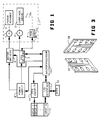
- Figure 1 is a block diagram of a thermal inkjet printer system;
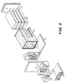
- Figure 2 is an exploded perspective view of one type of a thermal inkjet pen which is employable in practicing this invention;
- Figure 3 is a schematic fragment of the end of a flexible circuit in Figure 2 which engages the pickup end of a flexible circuit on the printer carriage, showing how the electrical connections are made;
- Figure 4 illustrates the layout or the format of the nozzles of a single color recorder head or pen of a type that may be employed in practicing this invention;
- Figure 5 illustrates the layout of the nozzle or orifice plate of Figure 2 showing the resistor networks;
- Figure 6 shows the actual electrical pad layout of the end of the flexible circuit attached to the detector of the printer carriage; and
- Figure 7 illustrates the logical concept of nine pen identity codes according to one specific embodiment of this invention.
- The block diagram of Figure 1 illustrate one type of printer control system. Such a system comprises a printer (shown here schematically) having a
chassis 1 on which acarriage 2 is slidable mounted for movement from one side to the other of paper in apaper advance mechanism 3 mounted in the chassis. Thepaper advance mechanism 3 moves the paper in an orthogonal direction with respect to the carriage. Acarriage motor 4 and apaper advance motor 5 drive the carriage and advance the paper under the control ofmotor drivers 6.Pen drivers 7, supplied with power from apower supply 8 individually energize the ink drop firing resistors of apen 9 which is secured on theprinter carriage 4 by means of apen attachment mechanism 9a. The ink drop firing resistors are not shown at this point. The system is controlled by a micro-processor 10 which receives data and instructions via an input-output interface 11 coupled to an instruction anddata source 12 for the system.Pen identification code 13 on thepen 9, which is a part of the pen ink drop firing, resistor network, is detected and the pen identification by means of thepen identification circuit 14 is used to select one of a plurality of inputs associated with the particular pen at theinput source 12, to provide instructions to themicroprocessor 10 for controlling that particular pen. Data for the particular text or graphics to be printed by the pen placed in the printer may be part of the selected input or may be separately programmed via the input-output interface 11 by adata source 15 where such provision is convenient. - With the
pen identification code 13 forming a part of the resistor network which fires the droplets from the individual nozzles of the pen, the pen drivers under the control of the microprocessor may interrogate the specific resistor circuits associated with the identification contact pads to obtain the pen identification code. This is done under the control of the microprocessor in which case the microprocessor, interpreting the signals derived from the specific code, provides a pen identification signal which may be coupled to the separatepen identity circuit 14, or used directly, to select one of the inputs, Input 1-Input 9, from theinstruction source 12, which may also include data for programming the microprocessor in its control of the printhead drivers as well as instructions for controlling the level of input of thepower supply 8, where needed, to properly control that particular pen. - One type of head which may be employed in practicing this invention is illustrated in the exploded perspective view of Figure 2. This is a thermal inkjet type of pen having a plurality of chambers individually isolated from one another for containing different colors of ink. The pen comprises a
pen body 20 having four individual chambers each of which receives a block offoam 21 saturated with ink of a selected color. Aback plate 22 seals thebody 20 and the individual chambers.Individual holes 23 in the front face of thepen body 20 provide communication for each pen body chamber withindividual openings 24 in afront plate 25 via fouropenings 26 in agasket 27 which seals thefront plate 25 to thepen body 20 and provides isolated communication of each pen body chamber with a selected one of theopenings 24 through thefront plate 25. Anozzle plate 30 which fits into acavity 31 in the front of thefront plate 25 is provided with groups ofnozzles 32 aligned with theopenings 24 in the front plate. Contactpads 33 along the opposite side edges of thenozzle plate 30 provide connection via circuit traces within the individual resistors at the individual nozzles. These details are shown in Figure 5. Theindividual contact pads 33 provide a means for selectively connecting electrical energy to the individual resistor circuits. Such connection is accomplished by means of aflexible circuit 35 provided withcircuit traces 36 terminating in contact pads along the back of the side edges of the slot in the flexible circuit. The pads are not visible here. This slot straddles thenozzle plate 30 in assembled position so that the contact pads on the back face of the flexible circuit engage thecontact pads 33 on the nozzle plate. The flexible circuit in assembled position extends beneath thepen body 20 where it is secured by pressuresensitive adhesive 37, or by other means, to the bottom side of thepen body 20. - There are electrical pad connections at both ends of the flexible circuit traces 36. One set of electrical contact pads, as stated above, is on the back side of the
flexible circuit 35 on the opposite sides of the slot therein, each of which engages a circuit trace in the flexible circuit. The ends of the circuit traces at the opposite end of theflexible circuit 35 are terminated in contact pads on the bottom side of theflexible circuit 35, as viewed. Figure 3 illustrates such typical connections. Figure 3 is not intended to represent specific connection configurations on theflexible circuit 35, but is intended merely to indicate how these connections are made. A fragment of theflexible circuit 35 is shown on the left in Figure 3 and may typically represent the contact pads on both ends of theflexible circuit 35. A secondflexible circuit 38, also comprising circuit traces and contact pads, represents, for example, a flexible circuit end on theprinter carriage 2 which engages the end of theflexible circuit 35 beneath thepen body 20, to provide electrical connection between thepen 9 on thecarriage 2 and printer drivers 7 (Fig. 1) which are located off the carriage. The contact pads on theflexible circuit 38 are provided with projecting dimples to provide positive engagement with the contact pads on the confronting section of theflexible circuit 35. Similar contacts may be provided between the contacts on theflexible circuit 35 and thecontact pads 33 on thenozzle plate 30. Such specific connections are illustrative and not limiting. - Simplifications in the control system firmware and programming are realized if formating of the nozzle configurations on the different types of pens are similar, for example, nozzle formats on a multicolor pen being similar to the nozzle format on a single color pen. Figure 4 illustrates the nozzle format for one type of single color pen. The nozzle plate of Figure 4 comprises two columns of nozzles there being 25 nozzles in each column. The nozzles in each column are arranged in staggered groups of 3 as seen. The nozzles in the right column which are odd numbered nozzles 1-49 are displaced vertically as viewed with respect to the nozzles in the left column which are the even numbered nozzles, 2-50, by one-half the distance between the nozzles in the columns.
TABLE I FIRING SEQUENCE SHIFT OFFSET (1PP) TIMING OFFSET (UM) 0 10 0 20,46 19,45 0.0 1 14,40 13,39 2.5 2 8,34 7,33 5.5 3 2,28 1,27 8.0 4 22,48 21,47 11.0 5 16,42 15,41 13.5 6 10,36 9,35 16.5 7 4,30 3,29 19.0 8 24,50 23,49 22.0 9 18,44 17,43 24.5 10 12,38 11,37 27.5 11 6,32 5,31 30.0 12 26 25 33.0 - Table I illustrates the firing sequence of the resistors associated with each of the nozzles of Figure 4. The location of these resistors will be apparent from Figure 5 discussed hereinafter. The resistors on the pen must be fired in a particular order to minimize cross talk. The location of the nozzles is set so that that dots will all be fired in the same vertical column when there is a constant scan or printing velocity. The dot firing sequence and relative nozzle locations in microns for a specific example are specified in Table I. When printing left to right the indicated sequence is used. When printing right to left the resistors are fired in the reverse sequence.
- The nozzle format of Figure 4 is retained in the individual nozzle groups of the
printhead 30 as seen in Figure 5. In affect the nozzle column of Figure 4 is divided by 4. Each nozzle group comprises 12 nozzles arrange in 2 columns of 6 having the dot row spacing between corresponding nozzles of respective rows and having the same column spacings as those of the single color pen. Since this multicolor pen has the same continuous dot per inch spacing with four color capability as the single color pen all of the single color printer text and graphics control characteristics are utilized. Only firmware and software require color capability. Formatting is required to provide the dot stagger offset between the nozzle groups. Thus within each nozzle group the ink drop firing sequence is the same as that of the single color pen. Figure 5 illustrates at an enlarged scale the layout of thenozzle plate 30 of Figure 2. Only the openings or thenozzles 32 of thenozzle plate 30 are shown in this Figure 5, since the figure is already highly detailed. Thesenozzles 32 are shown in their individual locations over the individual resistors R in the respective nozzle groups. The individual circuits or resistors R are connected by circuit traces C to the respective contact pads. The even numberedcontact pads 2 through 50 appear on the left side of Figure 5 and the odd numberedcontact pads 1 through 49 are shown on the right side of the substrate of Figure 5. The common contact pads for this substrate circuit system appear in the four corners of the substrate. - Only 48 of the 50 nozzles of Figure 4 are needed in developing the nozzle and circuit format of the
nozzle plate 30 of Figure 5. In this situation thenozzles TABLE II FIRING SEQUENCE 0 10 16 26 TIMING OFFSET (UM) 0 20 44 19 43 0 1 14 38 13 37 2.5 2 8 32 7 31 5.5 3 2 36 1 25 8.0 4 22 46 21 45 11.0 5 16 40 15 39 13.5 6 10 36 9 35 16.5 7 4 28 3 27 19.0 8 24 48 23 47 22.0 9 18 42 17 41 24.5 10 12 36 11 35 27.5 11 6 30 5 29 30.0 12 33.0 - Further and additional details with respect to nozzle formats for multicolor heads may be had by reference to a co-pending European application of C.S.Chan, et al, Application Number 88308650.6 filed 19 September 1988 entitled Multi-Chamber Ink Jet Recording Head for Color Use, assigned to the assignee of this invention and incorporated in its entirety in this application by reference thereto.
- Although the approach described above in formatting the nozzles in a multicolor head provide simplications noted above with respect to the control system and its programming, such nozzle formatting is not essential in practicing this invention. One approach to providing individual codes for identifying individual heads is discussed in connection with Figure 5. Similar considerations of course apply to other types of heads including
resistor substrates 31 having individual circuit pads, circuit traces and resistors for firing the ink drops. This of course applies to the single color nozzle format of Figure 4 except for the lateral displacement of the nozzles of the individual color groups as seen in Figure 5. - In reference to Figure 5 identification contact pads I1 and I2 are provided. The contact pad I1 is located between the
contact pads contact pads pad contact pad 48 or thecontact pad 50 or it may be connected to neither. The actual physical location of the contact pads at the end of theflexible circuit 35 beneath thepen body 20 may be seen by referring to Figure 6. Here the location of the common contact pads C1, C2, C3 and C4 at the end of theflexible circuit 35 are shown together with the locations of theindividual contact pads 1 through 50. Note in Figure 6 that the head identity contact pads I1 and I2 are located respectively betweencontact pads contact pads - In the circuit configurations described above there are nine possible code identities. These are depicted in Figure 7. Only some of the heads or pens are identified with a particular code to demonstrate the principal. In practice the head or pen needs to be interrogated only at the time that a printing operation is initiated. This therefore preferably occurs whether or not a pen is replaced with a different pen. By using this approach, there is certainty that a pen is always properly identified and a pen identification operation will therefore not be overlooked. Since pen identification interrogation occurs and is terminated prior to the commencement of a printing operation, pen identification in no way interferes with a printing operation. Additionally, although the
resistor circuits - In this connection it should be observed that the identification contact pads I1 and I2 may be located at any convenient location in the contact pad format of Figure 5. Additionally more than one contact pad in each column of contact pads may be used to provide a higher number of identification codes.
Claims (7)
- A dot-matrix printer (1) having a pen carriage (2); means (3) for advancing a print medium in a direction orthogonal to carriage movement; means (9a) for mounting different types of pens on the carriage; pen identification means (13 or I1, I2) on each pen providing a unique code for each pen; motor means (4) for driving the pen carriage (2) to move the pen (9) across the print medium; a control system (7,8,10), which system includes pen drivers (7), for operating the pen (9) for printing on the print medium during carriage movement; and means (12, 14) responsive to the code (13 or I1,I2) on said pen (9) for providing input to the control system (7,8,10) unique to said code; characterised in that each said pen (9) is a thermal inkjet pen; in that each said thermal inkjet pen (9) includes a nozzle plate (30) having a plurality of nozzles (32) and means (20, 23,24,26,27) for admitting ink to said nozzles (32); a resistor network having a resistor (R) at each nozzle (32), which resistor (R) when energised heats and expels ink from the nozzle (32) thereat; in that said pen identification means (I1,I2) includes patterns of resistors forming part of the resistor network and in that interrogation means forming part of said control system and including said pen drivers (7) is provided for energising the pen identification means (I1, I2) to obtain electrical signals identifying the pen (9).
- A printer according to claim1 in which the pen identification means (I1, I2) is energised by the interrogation means to obtain said electrical signals identifying said pen (9) prior to the commencement of each printing operation whether or not a pen is replaced with a different pen.
- A printer according to claim 1 or claim 2 wherein there are provided individual first contact pads (1-50) in the resistor network and individual circuits (C) connecting individual said first contact pads (1-50) to individual resistors (R); and at least two pen identification further contact pads (I1, I2), each disposed between selected different pairs (47, 49 and 48,50) of the first contact pads (1-50), and forming part of a pen identification network (7.14) including at least two resistors (R47, R49 for I1 and R48, R50 for I2) for each pen identification further contact pad (I1,I2).
- A printer according to claim 3, wherein said interrogation means sends pulses of electrical energy at different times to each resistor (R) at each pen identification further contact pad (I1, I2) and determines by the resulting voltage response, if an electrical connection between a resistor (R) and the associated pen identification further contact pad (I1, I2) exists.
- A printer according to claim 4, wherein said means (12,14) responsive to the code on said pen for providing input to the control system includes pen identification means (7.14) which utilises said voltage responses.
- A printer according to any preceding claim, wherein said different types of pens include single colour and multicolour pens.
- A printer according to claim 6, wherein each multicolour pen has a nozzle group for each colour of ink in the nozzle plate thereat, each nozzle group having the same nozzle format as the nozzles of a single colour pen but of a lesser number of nozzles than the number of nozzles for the single colour of ink of the single colour pen.
Applications Claiming Priority (2)
| Application Number | Priority Date | Filing Date | Title |
|---|---|---|---|
| US116093 | 1987-11-03 | ||
| US07/116,093 US4872027A (en) | 1987-11-03 | 1987-11-03 | Printer having identifiable interchangeable heads |
Publications (3)
| Publication Number | Publication Date |
|---|---|
| EP0315417A2 EP0315417A2 (en) | 1989-05-10 |
| EP0315417A3 EP0315417A3 (en) | 1991-10-16 |
| EP0315417B1 true EP0315417B1 (en) | 1995-03-22 |
Family
ID=22365191
Family Applications (1)
| Application Number | Title | Priority Date | Filing Date |
|---|---|---|---|
| EP88310277A Expired - Lifetime EP0315417B1 (en) | 1987-11-03 | 1988-11-01 | Printer having identifiable interchangeable recording heads or pens |
Country Status (7)
| Country | Link |
|---|---|
| US (1) | US4872027A (en) |
| EP (1) | EP0315417B1 (en) |
| JP (1) | JP2807708B2 (en) |
| KR (1) | KR930001244B1 (en) |
| CA (1) | CA1306897C (en) |
| DE (1) | DE3853403T2 (en) |
| HK (1) | HK7396A (en) |
Families Citing this family (126)
| Publication number | Priority date | Publication date | Assignee | Title |
|---|---|---|---|---|
| US5078523A (en) * | 1988-03-04 | 1992-01-07 | Varitronic Systems, Inc. | Tape cassette with identifying circuit element for printing machine |
| DE68921712T2 (en) * | 1988-12-16 | 1995-08-10 | Canon Kk | Recording device with removable recording head. |
| EP0376314B1 (en) * | 1988-12-29 | 1994-10-12 | Canon Kabushiki Kaisha | A liquid jet recording apparatus |
| JPH02198881A (en) * | 1989-01-27 | 1990-08-07 | Shimadzu Corp | Printer |
| US5049898A (en) * | 1989-03-20 | 1991-09-17 | Hewlett-Packard Company | Printhead having memory element |
| JP2845933B2 (en) * | 1989-04-24 | 1999-01-13 | キヤノン株式会社 | Recording head unit |
| JP2810701B2 (en) * | 1989-05-31 | 1998-10-15 | キヤノン株式会社 | Ink jet recording head and ink jet recording apparatus |
| ES2252908T3 (en) | 1989-08-05 | 2006-05-16 | Canon Kabushiki Kaisha | PRINTING DEVICE FOR INK JETS AND INK CARTRIDGE FOR THE APPLIANCE. |
| DE69033001T2 (en) | 1989-10-05 | 1999-09-09 | Canon Kk | Imaging device |
| US5365256A (en) * | 1989-12-29 | 1994-11-15 | Canon Kabushiki Kaisha | Recording apparatus with recording medium conveyance control for fixing recorded ink |
| USRE36279E (en) * | 1990-02-02 | 1999-08-24 | Canon Kabushiki Kaisha | Ink jet apparatus and ink jet cartridge therefor |
| JP2962838B2 (en) * | 1991-01-18 | 1999-10-12 | キヤノン株式会社 | Ink jet recording device |
| US5155497A (en) * | 1991-07-30 | 1992-10-13 | Hewlett-Packard Company | Service station for ink-jet printer |
| US5712666A (en) | 1991-08-09 | 1998-01-27 | Canon Kabushiki Kaisha | Recording apparatus |
| JP3351436B2 (en) * | 1991-08-21 | 2002-11-25 | セイコーエプソン株式会社 | Two-part adhesive sheet material having pores |
| CA2085568C (en) | 1991-12-19 | 2000-10-17 | Kenjiro Watanabe | Ink jet recording head, ink jet recording head cartridge and recording apparatus using same |
| JP3021149B2 (en) * | 1991-12-19 | 2000-03-15 | キヤノン株式会社 | Ink jet recording means |
| DE69325532T2 (en) * | 1992-03-09 | 1999-12-02 | Canon Kk | Multiple recording device using a monochrome printer |
| US5363134A (en) * | 1992-05-20 | 1994-11-08 | Hewlett-Packard Corporation | Integrated circuit printhead for an ink jet printer including an integrated identification circuit |
| US5504507A (en) * | 1992-10-08 | 1996-04-02 | Xerox Corporation | Electronically readable performance data on a thermal ink jet printhead chip |
| DE69328603T2 (en) * | 1992-10-15 | 2001-01-11 | Canon Kk | Ink jet recording device |
| WO1994011195A1 (en) * | 1992-11-12 | 1994-05-26 | Graphic Utilities, Inc. | Method for refilling ink jet cartridges |
| US5686948A (en) * | 1992-11-12 | 1997-11-11 | Graphic Utilities, Inc. | Method for refilling ink jet cartridges |
| US5318370A (en) * | 1992-11-17 | 1994-06-07 | Varitronic Systems, Inc. | Cartridge with data memory system and method regarding same |
| CA2110447C (en) * | 1992-12-03 | 2001-08-07 | Kazuyoshi Takahashi | Image output apparatus, image output method, ink jet print method and printed product obtained with said method |
| DE69328617T2 (en) * | 1993-04-30 | 2001-02-01 | Hewlett Packard Co | An improved unified connection system for an inkjet printer |
| DE69329041T2 (en) * | 1993-04-30 | 2001-03-22 | Hewlett Packard Co | Carriage assembly to hold two inkjet cartridges |
| US6003974A (en) * | 1993-04-30 | 1999-12-21 | Hewlett-Packard Company | Unitary interconnect system for an inkjet printer |
| SG75088A1 (en) * | 1993-04-30 | 2000-09-19 | Hewlett Packard Co | Common ink-jet cartridge platform for different printheads |
| JP3227268B2 (en) * | 1993-05-26 | 2001-11-12 | キヤノン株式会社 | Ink jet recording apparatus and ink jet recording method |
| IT1261605B (en) * | 1993-10-11 | 1996-05-23 | Olivetti & Co Spa | PRINTER WITH INTERCHANGEABLE PRINT HEADS |
| US6343857B1 (en) | 1994-02-04 | 2002-02-05 | Hewlett-Packard Company | Ink circulation in ink-jet pens |
| US5565900A (en) * | 1994-02-04 | 1996-10-15 | Hewlett-Packard Company | Unit print head assembly for ink-jet printing |
| US5949461A (en) * | 1994-02-18 | 1999-09-07 | Nu-Kote Imaging International, Inc. | Ink refill bottle |
| US6305786B1 (en) | 1994-02-23 | 2001-10-23 | Hewlett-Packard Company | Unit print head assembly for an ink-jet printer |
| US5635968A (en) * | 1994-04-29 | 1997-06-03 | Hewlett-Packard Company | Thermal inkjet printer printhead with offset heater resistors |
| JP3347527B2 (en) * | 1994-07-01 | 2002-11-20 | キヤノン株式会社 | Printer and printing method |
| JP3491972B2 (en) * | 1994-07-14 | 2004-02-03 | キヤノン株式会社 | Recording device and recording method |
| US6394571B1 (en) * | 1994-07-25 | 2002-05-28 | Canon Kabushiki Kaisha | Method and apparatus for controlling printing operation with externally supplied parameters |
| DE69514584T2 (en) * | 1994-07-29 | 2000-06-08 | Canon Kk | Printer with a removable print head |
| US5602574A (en) * | 1994-08-31 | 1997-02-11 | Hewlett-Packard Company | Matrix pen arrangement for inkjet printing |
| CA2164536A1 (en) | 1995-01-03 | 1996-07-04 | William G. Hawkins | Ink supply identification system |
| JPH0911527A (en) * | 1995-06-29 | 1997-01-14 | Tec Corp | Recording apparatus |
| US5742306A (en) * | 1995-07-31 | 1998-04-21 | Hewlett-Packard Company | Imaging cartridge system for inkjet printing mechanisms |
| US6082847A (en) * | 1995-09-01 | 2000-07-04 | Canon Kabushiki Kaisha | Image system with informing means |
| US6022094A (en) * | 1995-09-27 | 2000-02-08 | Lexmark International, Inc. | Memory expansion circuit for ink jet print head identification circuit |
| US5940095A (en) * | 1995-09-27 | 1999-08-17 | Lexmark International, Inc. | Ink jet print head identification circuit with serial out, dynamic shift registers |
| US5757394A (en) * | 1995-09-27 | 1998-05-26 | Lexmark International, Inc. | Ink jet print head identification circuit with programmed transistor array |
| DE69625308T2 (en) * | 1995-10-02 | 2003-07-03 | Canon Kk | Printer with a removable print head |
| JP3576694B2 (en) | 1996-04-23 | 2004-10-13 | キヤノン株式会社 | Ink jet recording method, apparatus thereof, image processing method, and printing method for executing image processing method |
| JPH09286125A (en) * | 1996-04-23 | 1997-11-04 | Canon Inc | Method for ink jet recording and apparatus therefor |
| JP3774505B2 (en) * | 1996-04-23 | 2006-05-17 | キヤノン株式会社 | Halftone recording apparatus, halftone recording method, ink tank, head cartridge, inkjet recording apparatus, and inkjet recording method |
| US6260938B1 (en) * | 1996-04-23 | 2001-07-17 | Canon Kabushiki Kaisha | Ink-jet printing method and apparatus for printing with inks of different densities |
| JPH1067127A (en) * | 1996-04-23 | 1998-03-10 | Canon Inc | Ink jet recording device and image processing method |
| US5831649A (en) * | 1996-05-17 | 1998-11-03 | Xerox Corporation | Thermal ink jet printing system including printhead with electronically encoded identification |
| US6460962B1 (en) | 1996-06-24 | 2002-10-08 | Xerox Corporation | Ink jet printer with sensing system for identifying various types of printhead cartridges |
| US6224184B1 (en) | 1996-07-01 | 2001-05-01 | Canon Kabushiki Kaisha | Printhead compatible with various printers and ink-jet printer using the printhead |
| EP0819533A3 (en) * | 1996-07-12 | 1998-11-25 | Canon Kabushiki Kaisha | A method for standardizing an ink jet jet recording head and an ink jet recording head for attaining such standardization, ink jet recording method, and information processing apparatus, and host apparatus |
| US6802659B2 (en) | 1996-08-07 | 2004-10-12 | Mats Cremon | Arrangement for automatic setting of programmable devices and materials therefor |
| KR100212992B1 (en) * | 1996-09-21 | 1999-08-02 | 윤종용 | Ink cartridge status detecting method of inkjet printer |
| US6655775B1 (en) * | 1996-10-15 | 2003-12-02 | Hewlett-Packard Development Company, L.P. | Method and apparatus for drop weight encoding |
| US5755519A (en) * | 1996-12-04 | 1998-05-26 | Fargo Electronics, Inc. | Printer ribbon identification sensor |
| US6168269B1 (en) | 1997-01-30 | 2001-01-02 | Hewlett-Packard Co. | Heated inkjet print media support system |
| US5877798A (en) * | 1997-03-21 | 1999-03-02 | Lexmark International Inc. | Method and apparatus for automatically determining the style printhead installed in a laser printer |
| US6108101A (en) * | 1997-05-15 | 2000-08-22 | Canon Kabushiki Kaisha | Technique for printing with different printer heads |
| JP3251530B2 (en) * | 1997-05-30 | 2002-01-28 | キヤノン株式会社 | Ink jet recording method and apparatus |
| EP0913264A3 (en) | 1997-10-28 | 1999-07-21 | Hewlett-Packard Company | Inkjet printhead service station |
| US6536871B1 (en) * | 1997-11-05 | 2003-03-25 | Hewlett-Packard Company | Reliable flex circuit interconnect on inkjet print cartridge |
| US6128098A (en) * | 1997-11-17 | 2000-10-03 | Canon Kabushiki Kaisha | Control over print head driving parameters |
| US6219153B1 (en) * | 1997-11-17 | 2001-04-17 | Canon Kabushiki Kaisha | Printer having a memory for storing a printer profile parameter |
| DE19752938C2 (en) * | 1997-11-28 | 2000-05-31 | Pelikan Produktions Ag Egg | Recoding of ink printheads |
| US6299274B1 (en) | 1997-12-15 | 2001-10-09 | Lexmark International, Inc. | Thermal ink jet printer cartridge identification |
| US6040670A (en) * | 1998-02-05 | 2000-03-21 | Canon Kabushiki Kaisha | Controller for printer carriage motor |
| US6109723A (en) * | 1998-03-12 | 2000-08-29 | Hewlett-Packard Company | Method and apparatus for determining an optimum print density for an ink jet printer |
| US6099101A (en) * | 1998-04-06 | 2000-08-08 | Lexmark International, Inc. | Disabling refill and reuse of an ink jet print head |
| JP3664218B2 (en) * | 1998-05-25 | 2005-06-22 | セイコーエプソン株式会社 | Ink jet recording apparatus and ink cartridge |
| US6161915A (en) * | 1998-06-19 | 2000-12-19 | Lexmark International, Inc | Identification of thermal inkjet printer cartridges |
| DE69942631D1 (en) * | 1998-08-31 | 2010-09-09 | Seiko Epson Corp | PRINTING DEVICE AND PRINT HEADER |
| EP1024005B1 (en) | 1999-01-29 | 2012-07-04 | Seiko Epson Corporation | Ink jet recording head and method of manufacturing the same |
| DE19914004B4 (en) * | 1999-03-29 | 2005-04-14 | Robert Bosch Gmbh | Identifiable electrical component with methods of identification and evaluation |
| US6332663B1 (en) * | 1999-06-16 | 2001-12-25 | Xerox Corporation | Methods and apparatus for marking images and obtaining image data using a single marking engine platform |
| US6152625A (en) * | 1999-07-27 | 2000-11-28 | Fargo Electronics, Inc. | Sensor hub for a print ribbon supply roll and method |
| KR100358341B1 (en) * | 1999-09-13 | 2002-10-25 | 삼성전자 주식회사 | Apparatus for decision of cartridge type in the printer for micro injecting device |
| US6549640B1 (en) | 1999-12-09 | 2003-04-15 | Pitney Bowes Inc. | System for metering and auditing the dots or drops or pulses produced by a digital printer in printing an arbitrary graphic |
| US6318856B1 (en) | 1999-12-09 | 2001-11-20 | Pitney Bowes Inc. | System for metering and auditing the dots or drops or pulses produced by a digital computer |
| US6361164B1 (en) | 1999-12-09 | 2002-03-26 | Pitney Bowes Inc. | System that meters the firings of a printer to audit the dots or drops or pulses produced by a digital printer |
| DE10011192A1 (en) * | 2000-03-08 | 2001-09-13 | Francotyp Postalia Gmbh | Franking machine with secured print head |
| JP4214661B2 (en) * | 2000-04-19 | 2009-01-28 | 富士フイルム株式会社 | Application system |
| US6325483B1 (en) | 2000-07-19 | 2001-12-04 | Hewlett-Packard Company | Techniques for increasing ink-jet pen identification information in an interconnect limited environment |
| US6349647B1 (en) | 2000-09-11 | 2002-02-26 | Hewlett-Packard Company | Apparatus and method for drying printing composition on a print medium |
| FR2816428B1 (en) * | 2000-11-07 | 2003-02-07 | Segepar | DRIVER CARD FOR INK JET PRINTHEADS |
| US7128408B2 (en) * | 2000-12-05 | 2006-10-31 | Seiko Epson Corporation | Printing apparatus and ink cartridge therefor |
| JP4023145B2 (en) * | 2000-12-05 | 2007-12-19 | セイコーエプソン株式会社 | Printing device, ink cartridge |
| JP2002321392A (en) * | 2001-03-02 | 2002-11-05 | Oce Technologies Bv | Constitution method for printer and ink cartridge |
| US6616268B2 (en) | 2001-04-12 | 2003-09-09 | Lexmark International, Inc. | Power distribution architecture for inkjet heater chip |
| US6616260B2 (en) | 2001-05-25 | 2003-09-09 | Hewlett-Packard Development Company, L.P. | Robust bit scheme for a memory of a replaceable printer component |
| US20040257402A1 (en) * | 2001-07-13 | 2004-12-23 | Lynch Patrick J | Printhead for a printer cartridge |
| US6604814B2 (en) * | 2001-09-28 | 2003-08-12 | Hewlett-Packard Development Company, Lp | Arrangements of interconnect circuit and fluid drop generators |
| US6568785B1 (en) | 2002-03-18 | 2003-05-27 | Lexmark International, Inc | Integrated ink jet print head identification system |
| TW590897B (en) * | 2002-04-30 | 2004-06-11 | Ind Tech Res Inst | Method for manufacturing identification circuit of inkjet print-head chip |
| AU2002323370A1 (en) * | 2002-08-22 | 2004-03-11 | Mvm Products, Llc | Universal inkjet printer device and methods |
| US6827420B2 (en) | 2002-12-18 | 2004-12-07 | Lexmark International, Inc. | Device verification using printed patterns and optical sensing |
| US7015795B2 (en) * | 2002-12-30 | 2006-03-21 | Potomac Photonics, Inc. | Self-identifying integrated circuits and method for fabrication thereof |
| US7240995B2 (en) * | 2003-05-06 | 2007-07-10 | Lexmark International, Inc. | Method of authenticating a consumable |
| US7249825B2 (en) * | 2003-05-09 | 2007-07-31 | Hewlett-Packard Development Company, L.P. | Fluid ejection device with data storage structure |
| US7216968B2 (en) * | 2003-05-24 | 2007-05-15 | Hewlett-Packard Development Company, L.P. | Media electrostatic hold down and conductive heating assembly |
| US7032994B2 (en) | 2003-10-31 | 2006-04-25 | Hewlett-Packard Development Company, L.P. | Interconnect circuit |
| US7137690B2 (en) * | 2003-10-31 | 2006-11-21 | Hewlett-Packard Development Company, L.P. | Interconnect circuit |
| US7101029B2 (en) * | 2003-10-31 | 2006-09-05 | Hewlett-Packard Development Company, L.P. | Interconnect circuit |
| US7237864B2 (en) | 2004-02-06 | 2007-07-03 | Hewlett-Packard Development Company, L.P. | Fluid ejection device identification |
| US6997549B2 (en) * | 2004-02-26 | 2006-02-14 | Hewlett-Packard Development Company, L.P. | Media hold down system |
| US8099791B1 (en) | 2004-06-25 | 2012-01-17 | Lexmark International, Inc. | Method of authenticating a consumable in an imaging device |
| US7494215B2 (en) * | 2004-10-29 | 2009-02-24 | Hewlett-Packard Development Company, L.P. | Multiple chamber ink cartridge |
| WO2006062686A2 (en) * | 2004-11-12 | 2006-06-15 | Pertech Resources Inc. | Transaction printer |
| JP4963555B2 (en) * | 2005-04-28 | 2012-06-27 | キヤノン株式会社 | Inkjet recording head |
| JP4756928B2 (en) * | 2005-06-21 | 2011-08-24 | キヤノン株式会社 | Printer |
| US7604317B2 (en) * | 2005-06-21 | 2009-10-20 | Canon Kabushiki Kaisha | Recording apparatus capable of checking positions of ink containers, and method for checking the positions |
| US7950862B2 (en) | 2006-05-26 | 2011-05-31 | Youngtack Shim | Multicolor writing tools and methods |
| JP4442674B2 (en) * | 2007-09-26 | 2010-03-31 | 富士ゼロックス株式会社 | Print control device |
| JP5430167B2 (en) * | 2009-02-06 | 2014-02-26 | キヤノン株式会社 | Liquid discharge head |
| US8714719B2 (en) | 2012-04-17 | 2014-05-06 | Kateeva, Inc. | Printhead unit assembly for use with an inkjet printing system |
| US10214019B2 (en) | 2012-04-30 | 2019-02-26 | Hewlett-Packard Development Company, L.P. | Flexible substrate with integrated circuit |
| CN103386816B (en) * | 2012-05-11 | 2016-01-20 | 科迪华公司 | For the printhead unit assembly of ink-jet print system |
| TWI540056B (en) * | 2012-05-11 | 2016-07-01 | 凱特伊夫公司 | Printhead unit assembly for use with an inkjet printing system |
| US9630400B2 (en) | 2013-10-15 | 2017-04-25 | Hewlett-Packard Development Company, L.P. | Authentication value for print head die based on analog device electrical characteristics |
| KR20220163528A (en) | 2016-07-18 | 2022-12-09 | 카티바, 인크. | Printing system assemblies and techniques |
Family Cites Families (10)
| Publication number | Priority date | Publication date | Assignee | Title |
|---|---|---|---|---|
| JPS55152080A (en) * | 1979-05-16 | 1980-11-27 | Canon Inc | Recorder |
| JPS56167484A (en) * | 1980-05-30 | 1981-12-23 | Canon Inc | Printer |
| DE3273442D1 (en) * | 1982-06-30 | 1986-10-30 | Ibm | Print head assembly for non-impact printing |
| DE3233425A1 (en) * | 1982-09-09 | 1984-04-05 | Olympia Werke Ag, 2940 Wilhelmshaven | Matrix printer with a replaceable print head |
| DE3342894A1 (en) * | 1983-11-26 | 1985-06-05 | Olympia Werke Ag, 2940 Wilhelmshaven | CASSETTE FOR A WRITING HEAD OF AN INK WRITING DEVICE IN A TYPEWRITER |
| US4633274A (en) * | 1984-03-30 | 1986-12-30 | Canon Kabushiki Kaisha | Liquid ejection recording apparatus |
| US4771295B1 (en) * | 1986-07-01 | 1995-08-01 | Hewlett Packard Co | Thermal ink jet pen body construction having improved ink storage and feed capability |
| US4803500A (en) * | 1986-07-04 | 1989-02-07 | Siemens Aktiengesellschaft | Ink printer means comprising interchangeable ink heads |
| US4774529A (en) * | 1987-02-26 | 1988-09-27 | Xerox Corporation | Repositionable marking head for increasing printing speed |
| US4812859A (en) * | 1987-09-17 | 1989-03-14 | Hewlett-Packard Company | Multi-chamber ink jet recording head for color use |
-
1987
- 1987-11-03 US US07/116,093 patent/US4872027A/en not_active Expired - Lifetime
-
1988
- 1988-08-08 CA CA000574125A patent/CA1306897C/en not_active Expired - Lifetime
- 1988-11-01 EP EP88310277A patent/EP0315417B1/en not_active Expired - Lifetime
- 1988-11-01 DE DE3853403T patent/DE3853403T2/en not_active Expired - Lifetime
- 1988-11-02 JP JP63278502A patent/JP2807708B2/en not_active Expired - Fee Related
- 1988-11-02 KR KR1019880014365A patent/KR930001244B1/en not_active IP Right Cessation
-
1996
- 1996-01-18 HK HK7396A patent/HK7396A/en not_active IP Right Cessation
Also Published As
| Publication number | Publication date |
|---|---|
| HK7396A (en) | 1996-01-26 |
| DE3853403D1 (en) | 1995-04-27 |
| DE3853403T2 (en) | 1995-07-27 |
| EP0315417A3 (en) | 1991-10-16 |
| CA1306897C (en) | 1992-09-01 |
| KR900008410A (en) | 1990-06-04 |
| KR930001244B1 (en) | 1993-02-22 |
| JPH02513A (en) | 1990-01-05 |
| JP2807708B2 (en) | 1998-10-08 |
| EP0315417A2 (en) | 1989-05-10 |
| US4872027A (en) | 1989-10-03 |
Similar Documents
| Publication | Publication Date | Title |
|---|---|---|
| EP0315417B1 (en) | Printer having identifiable interchangeable recording heads or pens | |
| US5953028A (en) | Interconnect scheme for mounting differently configured printheads on the same carriage | |
| US4803500A (en) | Ink printer means comprising interchangeable ink heads | |
| EP0308272B2 (en) | Multi-chamber ink jet recording head for color use | |
| EP0863004B2 (en) | Dynamic multi-pass print mode corrections to compensate for malfunctioning inkjet nozzles | |
| EP0730967B1 (en) | Simultaneously printing with different sections of printheads for improved print quality | |
| EP0654352B1 (en) | Mixed resolution printing for colour and monochrome printers | |
| US6109722A (en) | Ink jet printing system with pen alignment and method | |
| US5764254A (en) | Alignment of differently sized printheads in a printer | |
| US4750009A (en) | Color ink jet system printer capable of high definition printing | |
| US6685297B2 (en) | Print head alignment method, test pattern used in the method, and a system thereof | |
| EP0225168B1 (en) | Impulse ink jet apparatus | |
| US5912683A (en) | Method of printing with an ink jet printer using an enhanced horizontal resolution | |
| US5975679A (en) | Dot alignment in mixed resolution printer | |
| EP0961222B1 (en) | Serial interleaved ink jet printing | |
| US4588316A (en) | Optically controlled multi-color impact printer | |
| US5796417A (en) | Compliant interconnect assembly for mounting removable print cartridges in a carriage | |
| EP0730969B1 (en) | Dot alignment in mixed resolution printer | |
| EP1145854B1 (en) | A printhead substrate having ink drop generators arranged in groups that span both edges of an ink feed channel | |
| US6328413B1 (en) | Inkjet printer spitting method for reducing print cartridge cross-contamination | |
| JPS5842465A (en) | Multi-color printer | |
| JPH02198848A (en) | Ink-jet recorder | |
| CA1181987A (en) | Print head for high resolution electrothermal printing apparatus | |
| EP0113423B1 (en) | Impact printer | |
| JPH1158705A (en) | Recorder |
Legal Events
| Date | Code | Title | Description |
|---|---|---|---|
| PUAI | Public reference made under article 153(3) epc to a published international application that has entered the european phase |
Free format text: ORIGINAL CODE: 0009012 |
|
| AK | Designated contracting states |
Kind code of ref document: A2 Designated state(s): DE FR GB IT |
|
| PUAL | Search report despatched |
Free format text: ORIGINAL CODE: 0009013 |
|
| AK | Designated contracting states |
Kind code of ref document: A3 Designated state(s): DE FR GB IT |
|
| 17P | Request for examination filed |
Effective date: 19920117 |
|
| 17Q | First examination report despatched |
Effective date: 19930802 |
|
| GRAA | (expected) grant |
Free format text: ORIGINAL CODE: 0009210 |
|
| AK | Designated contracting states |
Kind code of ref document: B1 Designated state(s): DE FR GB IT |
|
| REF | Corresponds to: |
Ref document number: 3853403 Country of ref document: DE Date of ref document: 19950427 |
|
| ET | Fr: translation filed | ||
| ITF | It: translation for a ep patent filed |
Owner name: SOCIETA' ITALIANA BREVETTI S.P.A. |
|
| PLBE | No opposition filed within time limit |
Free format text: ORIGINAL CODE: 0009261 |
|
| STAA | Information on the status of an ep patent application or granted ep patent |
Free format text: STATUS: NO OPPOSITION FILED WITHIN TIME LIMIT |
|
| 26N | No opposition filed | ||
| REG | Reference to a national code |
Ref country code: GB Ref legal event code: 732E |
|
| REG | Reference to a national code |
Ref country code: FR Ref legal event code: TP |
|
| REG | Reference to a national code |
Ref country code: FR Ref legal event code: CL |
|
| REG | Reference to a national code |
Ref country code: GB Ref legal event code: IF02 |
|
| PGFP | Annual fee paid to national office [announced via postgrant information from national office to epo] |
Ref country code: IT Payment date: 20071129 Year of fee payment: 20 |
|
| PGFP | Annual fee paid to national office [announced via postgrant information from national office to epo] |
Ref country code: FR Payment date: 20071119 Year of fee payment: 20 Ref country code: GB Payment date: 20071128 Year of fee payment: 20 |
|
| PGFP | Annual fee paid to national office [announced via postgrant information from national office to epo] |
Ref country code: DE Payment date: 20071221 Year of fee payment: 20 |
|
| REG | Reference to a national code |
Ref country code: GB Ref legal event code: PE20 Expiry date: 20081031 |
|
| PG25 | Lapsed in a contracting state [announced via postgrant information from national office to epo] |
Ref country code: GB Free format text: LAPSE BECAUSE OF EXPIRATION OF PROTECTION Effective date: 20081031 |