EP0316796A2 - Intravascular ultrasonic catheter probe for treating intravascular blockage - Google Patents
Intravascular ultrasonic catheter probe for treating intravascular blockage Download PDFInfo
- Publication number
- EP0316796A2 EP0316796A2 EP88118819A EP88118819A EP0316796A2 EP 0316796 A2 EP0316796 A2 EP 0316796A2 EP 88118819 A EP88118819 A EP 88118819A EP 88118819 A EP88118819 A EP 88118819A EP 0316796 A2 EP0316796 A2 EP 0316796A2
- Authority
- EP
- European Patent Office
- Prior art keywords
- probe
- catheter
- blood vessel
- tip
- ultrasonic energy
- Prior art date
- Legal status (The legal status is an assumption and is not a legal conclusion. Google has not performed a legal analysis and makes no representation as to the accuracy of the status listed.)
- Granted
Links
Images

Classifications
-
- A—HUMAN NECESSITIES
- A61—MEDICAL OR VETERINARY SCIENCE; HYGIENE
- A61B—DIAGNOSIS; SURGERY; IDENTIFICATION
- A61B17/00—Surgical instruments, devices or methods, e.g. tourniquets
- A61B17/22—Implements for squeezing-off ulcers or the like on the inside of inner organs of the body; Implements for scraping-out cavities of body organs, e.g. bones; Calculus removers; Calculus smashing apparatus; Apparatus for removing obstructions in blood vessels, not otherwise provided for
- A61B17/22004—Implements for squeezing-off ulcers or the like on the inside of inner organs of the body; Implements for scraping-out cavities of body organs, e.g. bones; Calculus removers; Calculus smashing apparatus; Apparatus for removing obstructions in blood vessels, not otherwise provided for using mechanical vibrations, e.g. ultrasonic shock waves
- A61B17/22012—Implements for squeezing-off ulcers or the like on the inside of inner organs of the body; Implements for scraping-out cavities of body organs, e.g. bones; Calculus removers; Calculus smashing apparatus; Apparatus for removing obstructions in blood vessels, not otherwise provided for using mechanical vibrations, e.g. ultrasonic shock waves in direct contact with, or very close to, the obstruction or concrement
-
- A—HUMAN NECESSITIES
- A61—MEDICAL OR VETERINARY SCIENCE; HYGIENE
- A61B—DIAGNOSIS; SURGERY; IDENTIFICATION
- A61B17/00—Surgical instruments, devices or methods, e.g. tourniquets
- A61B2017/00017—Electrical control of surgical instruments
- A61B2017/00137—Details of operation mode
- A61B2017/00141—Details of operation mode continuous, e.g. wave
-
- A—HUMAN NECESSITIES
- A61—MEDICAL OR VETERINARY SCIENCE; HYGIENE
- A61B—DIAGNOSIS; SURGERY; IDENTIFICATION
- A61B17/00—Surgical instruments, devices or methods, e.g. tourniquets
- A61B2017/00017—Electrical control of surgical instruments
- A61B2017/00137—Details of operation mode
- A61B2017/00154—Details of operation mode pulsed
-
- A—HUMAN NECESSITIES
- A61—MEDICAL OR VETERINARY SCIENCE; HYGIENE
- A61B—DIAGNOSIS; SURGERY; IDENTIFICATION
- A61B17/00—Surgical instruments, devices or methods, e.g. tourniquets
- A61B17/22—Implements for squeezing-off ulcers or the like on the inside of inner organs of the body; Implements for scraping-out cavities of body organs, e.g. bones; Calculus removers; Calculus smashing apparatus; Apparatus for removing obstructions in blood vessels, not otherwise provided for
- A61B17/22004—Implements for squeezing-off ulcers or the like on the inside of inner organs of the body; Implements for scraping-out cavities of body organs, e.g. bones; Calculus removers; Calculus smashing apparatus; Apparatus for removing obstructions in blood vessels, not otherwise provided for using mechanical vibrations, e.g. ultrasonic shock waves
- A61B2017/22005—Effects, e.g. on tissue
- A61B2017/22007—Cavitation or pseudocavitation, i.e. creation of gas bubbles generating a secondary shock wave when collapsing
- A61B2017/22008—Cavitation or pseudocavitation, i.e. creation of gas bubbles generating a secondary shock wave when collapsing used or promoted
-
- A—HUMAN NECESSITIES
- A61—MEDICAL OR VETERINARY SCIENCE; HYGIENE
- A61B—DIAGNOSIS; SURGERY; IDENTIFICATION
- A61B17/00—Surgical instruments, devices or methods, e.g. tourniquets
- A61B17/22—Implements for squeezing-off ulcers or the like on the inside of inner organs of the body; Implements for scraping-out cavities of body organs, e.g. bones; Calculus removers; Calculus smashing apparatus; Apparatus for removing obstructions in blood vessels, not otherwise provided for
- A61B2017/22038—Implements for squeezing-off ulcers or the like on the inside of inner organs of the body; Implements for scraping-out cavities of body organs, e.g. bones; Calculus removers; Calculus smashing apparatus; Apparatus for removing obstructions in blood vessels, not otherwise provided for with a guide wire
-
- A—HUMAN NECESSITIES
- A61—MEDICAL OR VETERINARY SCIENCE; HYGIENE
- A61B—DIAGNOSIS; SURGERY; IDENTIFICATION
- A61B17/00—Surgical instruments, devices or methods, e.g. tourniquets
- A61B17/22—Implements for squeezing-off ulcers or the like on the inside of inner organs of the body; Implements for scraping-out cavities of body organs, e.g. bones; Calculus removers; Calculus smashing apparatus; Apparatus for removing obstructions in blood vessels, not otherwise provided for
- A61B2017/22051—Implements for squeezing-off ulcers or the like on the inside of inner organs of the body; Implements for scraping-out cavities of body organs, e.g. bones; Calculus removers; Calculus smashing apparatus; Apparatus for removing obstructions in blood vessels, not otherwise provided for with an inflatable part, e.g. balloon, for positioning, blocking, or immobilisation
-
- A—HUMAN NECESSITIES
- A61—MEDICAL OR VETERINARY SCIENCE; HYGIENE
- A61B—DIAGNOSIS; SURGERY; IDENTIFICATION
- A61B17/00—Surgical instruments, devices or methods, e.g. tourniquets
- A61B17/32—Surgical cutting instruments
- A61B17/320068—Surgical cutting instruments using mechanical vibrations, e.g. ultrasonic
- A61B2017/320098—Surgical cutting instruments using mechanical vibrations, e.g. ultrasonic with transverse or torsional motion
-
- A—HUMAN NECESSITIES
- A61—MEDICAL OR VETERINARY SCIENCE; HYGIENE
- A61B—DIAGNOSIS; SURGERY; IDENTIFICATION
- A61B18/00—Surgical instruments, devices or methods for transferring non-mechanical forms of energy to or from the body
- A61B2018/00005—Cooling or heating of the probe or tissue immediately surrounding the probe
- A61B2018/00011—Cooling or heating of the probe or tissue immediately surrounding the probe with fluids
- A61B2018/00029—Cooling or heating of the probe or tissue immediately surrounding the probe with fluids open
- A61B2018/00035—Cooling or heating of the probe or tissue immediately surrounding the probe with fluids open with return means
-
- A—HUMAN NECESSITIES
- A61—MEDICAL OR VETERINARY SCIENCE; HYGIENE
- A61B—DIAGNOSIS; SURGERY; IDENTIFICATION
- A61B18/00—Surgical instruments, devices or methods for transferring non-mechanical forms of energy to or from the body
- A61B2018/00982—Surgical instruments, devices or methods for transferring non-mechanical forms of energy to or from the body combined with or comprising means for visual or photographic inspections inside the body, e.g. endoscopes
-
- A—HUMAN NECESSITIES
- A61—MEDICAL OR VETERINARY SCIENCE; HYGIENE
- A61B—DIAGNOSIS; SURGERY; IDENTIFICATION
- A61B90/00—Instruments, implements or accessories specially adapted for surgery or diagnosis and not covered by any of the groups A61B1/00 - A61B50/00, e.g. for luxation treatment or for protecting wound edges
- A61B90/36—Image-producing devices or illumination devices not otherwise provided for
- A61B90/37—Surgical systems with images on a monitor during operation
- A61B2090/376—Surgical systems with images on a monitor during operation using X-rays, e.g. fluoroscopy
-
- A—HUMAN NECESSITIES
- A61—MEDICAL OR VETERINARY SCIENCE; HYGIENE
- A61B—DIAGNOSIS; SURGERY; IDENTIFICATION
- A61B90/00—Instruments, implements or accessories specially adapted for surgery or diagnosis and not covered by any of the groups A61B1/00 - A61B50/00, e.g. for luxation treatment or for protecting wound edges
- A61B90/39—Markers, e.g. radio-opaque or breast lesions markers
- A61B2090/3933—Liquid markers
-
- A—HUMAN NECESSITIES
- A61—MEDICAL OR VETERINARY SCIENCE; HYGIENE
- A61B—DIAGNOSIS; SURGERY; IDENTIFICATION
- A61B2217/00—General characteristics of surgical instruments
- A61B2217/002—Auxiliary appliance
- A61B2217/005—Auxiliary appliance with suction drainage system
-
- A—HUMAN NECESSITIES
- A61—MEDICAL OR VETERINARY SCIENCE; HYGIENE
- A61B—DIAGNOSIS; SURGERY; IDENTIFICATION
- A61B2217/00—General characteristics of surgical instruments
- A61B2217/002—Auxiliary appliance
- A61B2217/007—Auxiliary appliance with irrigation system
-
- A—HUMAN NECESSITIES
- A61—MEDICAL OR VETERINARY SCIENCE; HYGIENE
- A61M—DEVICES FOR INTRODUCING MEDIA INTO, OR ONTO, THE BODY; DEVICES FOR TRANSDUCING BODY MEDIA OR FOR TAKING MEDIA FROM THE BODY; DEVICES FOR PRODUCING OR ENDING SLEEP OR STUPOR
- A61M25/00—Catheters; Hollow probes
- A61M25/10—Balloon catheters
- A61M2025/1043—Balloon catheters with special features or adapted for special applications
- A61M2025/1047—Balloon catheters with special features or adapted for special applications having centering means, e.g. balloons having an appropriate shape
-
- A—HUMAN NECESSITIES
- A61—MEDICAL OR VETERINARY SCIENCE; HYGIENE
- A61M—DEVICES FOR INTRODUCING MEDIA INTO, OR ONTO, THE BODY; DEVICES FOR TRANSDUCING BODY MEDIA OR FOR TAKING MEDIA FROM THE BODY; DEVICES FOR PRODUCING OR ENDING SLEEP OR STUPOR
- A61M25/00—Catheters; Hollow probes
- A61M25/10—Balloon catheters
- A61M2025/1043—Balloon catheters with special features or adapted for special applications
- A61M2025/1052—Balloon catheters with special features or adapted for special applications for temporarily occluding a vessel for isolating a sector
-
- A—HUMAN NECESSITIES
- A61—MEDICAL OR VETERINARY SCIENCE; HYGIENE
- A61M—DEVICES FOR INTRODUCING MEDIA INTO, OR ONTO, THE BODY; DEVICES FOR TRANSDUCING BODY MEDIA OR FOR TAKING MEDIA FROM THE BODY; DEVICES FOR PRODUCING OR ENDING SLEEP OR STUPOR
- A61M25/00—Catheters; Hollow probes
- A61M25/0067—Catheters; Hollow probes characterised by the distal end, e.g. tips
Definitions
- This invention relates to therapeutic treatment for the removal of intravascular blockage due to atherosclerotic plaque and intravascular blood clots and, more particularly, to a method and apparatus for the removal of atherosclerotic plaque and blood clots in blood vessels by the use of ultrasonic energy.
- the arteries must have sufficient elasticity to expand with each heartbeat and to withstand the high pressures of arterial blood flow.
- cholesterol, fibrous material, and other substances coat the inner surface of arteries, there can be a severe loss in blood vessel elasticity. This condition is commonly referred to as atherosclerosis.
- atherosclerosis In addition to cholesterol and fibrous materials, calcium deposits may accumulate that can further reduce the elasticity of the blood vessel and can cause the accumulated deposits to become hard.
- the deposits are most frequently associated with the blood vessels supplying the heart, but the deposits may occur elsewhere in the body. These deposits, which are generally referred to as plaque, accumulate at one location and drastically narrow the bore of the artery, thus restricting and even totally blocking the flow of blood. Plaque has a thick, viscous consistency. The site of accumulated deposits that constrict the blood vessel is referred to as a stenosis while a total blockage is referred to as an occlusion. Similarly, a blood clot is often associated with the blood vessels supplying the heart, but may occur elsewhere in the body. An intravascular blood clot is generally referred to as a thrombosis.
- Arterial bypass surgery involves the bypass of the narrowed or occluded arterial segment by using a synthetic conduit or an arterial or venous graft to carry blood past the arterial obstruction. Arterial bypass surgery requires surgery, with the attendant risks of surgery and general anesthesia, problems of wound healing and infection, post-operative complications, and the problem of post-operative graft closure.
- Endarterectomy also requires direct surgery, but further requires that the blocked blood vessel itself be opened and the blockage removed. That is, the blood vessel is exposed during surgery, the vessel is slit open along the blocked portion, and the blockage is manually removed by the physician. The slit must then be sealed up so that blood may once again flow through the vessel.
- this technique is in many ways more invasive than bypass surgery and includes all of its potential shortcomings.
- Balloon angioplasty is a recent development that involves the insertion of a catheter having a circumferential balloon attached at its distal end.
- a thin, flexible guide wire is first inserted in the blood vessel and is advanced to the site of a stenosis.
- a catheter is then slipped over the guide wire and is advanced in the blood vessel along the length of the wire.
- the balloon is inflated and thereby dilates the stenotic arterial segments. This stretches the artery and may obviate the need for arterial bypass operations.
- the limitations of balloon angioplasty include arterial dissection, bleeding, and re-occlusion.
- a "hot-tip" catheter for example, can be used for most fibrous blockages but cannot be used for totally calcified blockages.
- a hot-tip catheter also has an increased risk of perforation.
- Drill techniques typically employ a stiff, threaded probe that rotates and thereby drills or reams out the plaque. These techniques also present a high damage potential, primarily due to perforation, and therefore direct visual observation of the site may be necessary.
- direct visual observation it may be necessary to use angioscopy to insert a fiber optic probe into the blood vessel, further complicating the treatment process.
- Angioscopy involves the insertion of an angioscope, or fiber optic probe, into the blood vessel for visual inspection of the treatment site.
- direct surgical techniques would be necessary.
- the device of U.S. Patent No. 3,526,219 to Balamuth utilizes ultrasonic energy but is used for the removal of tumors, warts, moles, skin cancer, and others from the surface of skin tissue.
- the device has no application to the interior of blood vessels.
- the device of U.S. Patent No. 3,433,226 to Boyd relates to a catheter that vibrates at an ultrasonic resonant frequency to destroy plaque. Because the catheter itself vibrates adjacent to the blood vessel wall, and is advanced in the blood vessel for destruction of the stenosis, there is a danger of perforation of the vessel wall during application of ultrasonic energy. Thus, these previous ultrasonic methods of treating plaque still include many undesirable complications and dangers.
- the present invention provides a method and apparatus for removing intravascular blockage due to atherosclerosis or blood clots.
- Some of the advantages of the apparatus of the present invention and methods of use thereof are rapid destruction of arterial stenoses (on the order of seconds rather than minutes, as with other techniques), low risk of rupture of arterial walls, lack of significant damage to normal healthy vessels, the ability to open blood vessels that are totally occluded by atherosclerotic fibrous plaque and/or calcified plaque, the ability to dissolve occlusive and non-occlusive clots within blood vessels, and the ability to perform the procedure at the time of a diagnostic angiogram, thus obviating the need for surgery.
- angioscope a fiber optic probe inserted within a catheter
- the apparatus of the present invention comprises an elongated, flexible wire probe having a bulbous tip and carried within a catheter or sheath made of or coated with a plastic or other friction-reducing material.
- the end of the probe having the bulbous tip is placed in contact with an intravascular blockage and the other end of the probe is attached to an ultrasonic power source.
- the bulbous tip reduces the risk of blood vessel perforation as compared with the techniques discussed above.
- the probe carries ultrasonic energy from the ultrasonic power source to the site of intravascular blockage. Unlike most ultrasonic catheter/probe combinations, the flexible probe is made to vibrate transversely as well as forward and backward.
- the catheter may also be connected to the ultrasonic power source but does not vibrate and is used only to act as a conduit for placement of the flexible probe at the site of blockage and for carrying radiographic contrast fluid into the blood vessel.
- the catheter also may be provided with an annular inflatable cuff at its distal end for centering the catheter/probe and sealing off the treatment site.
- Conventional angiography insertion techniques can be used to insert the apparatus of the present invention into the blood vessel, thus eliminating surgical procedures. After the catheter and probe are inserted in the blood vessel, they are advanced upstream of blood flow to the site of blockage.
- the advantage of the angiographic insertion technique is that surgery is not required and the patient is not under general anesthesia.
- the treatment method and apparatus of the present invention also may be used with insertion techniques besides that of the angiogram in order to gain access to the blood vessel interior.
- the apparatus may be used along with direct surgery techniques for more effective removal of intravascular blockages.
- a radiographic contrast fluid that appears nearly opaque in an x-ray image is infused in the catheter, which is otherwise nearly transparent in an x-ray image.
- the contrast fluid may be released in the blood vessel in controlled quantities, so as to fill the blood vessel and clearly expose it to observation in real-time on an x-ray video image monitor, such as a fluoroscope.
- an x-ray video image monitor such as a fluoroscope.
- the artery and the progress of the catheter and probe in the artery may be observed.
- direct visual observation of the artery as the catheter moves along in the artery is probably unnecessary and the fiber optic catheter normally used with angioscopy techniques is probably not needed. Nevertheless, direct visual observation may be used along with the disclosed method and apparatus, if desired.
- the balloon may be inflated to contact the blood vessel wall once the catheter is at the treatment site, thereby centering the catheter within the blood vessel and blocking off the treatment site.
- the probe With the catheter centered, the probe is less likely to veer off-axis within the blood vessel when it is extended, and is more likely to remain equidistant from the vessel wall during extension from the catheter and during ultrasonic vibration. This further reduces the chances of vessel perforation and damage to healthy tissue. Blocking off the treatment site aids in aspiration of most if not all particles of debris and helps to prevent particles from escaping backward into the bloodstream.
- the probe When the catheter is at the appropriate arterial location, the probe may be advanced outside of the catheter to come into contact with the plaque or thrombosis.
- the ultrasonic power source may be activated to supply continuous or pulsed ultrasonic energy to the mass of plaque or thrombosis through the probe tip.
- the ultrasonic energy is pulsed at 20 millisecond intervals, being on for 20 msec. and off for 20 msec. This prevents the probe tip from becoming heated. Since a hot probe is more likely to perforate a vessel wall than a cool probe, this helps to further reduce the chances of perforation.
- More contrast fluid or contrast fluid of a higher concentration may be let into the artery once ultrasonic treatment begins and then the progress of the contrast fluid in the artery may be viewed in real-time on an x-ray image video monitor screen. This allows the progress of the treatment in removing the stenosis to be observed by noting the flow of radiographic contrast fluid. If the contrast fluid does not move along in the blood vessel, the occlusion is still present. Again, direct visual observation of the treatment site is ordinarily unnecessary.
- Physiologic saline or other physiologic solutions may also be inserted into the hollow catheter to flow around the probe to the site of the arterial stenosis.
- the catheter may be provided with multiple lumens, or passageways, for the passage of fluids to and from the treatment site.
- the temperature of the probe tip may be further controlled during the application of ultrasonic energy by varying the rate of infusion of the physiologic solution. This prevents undue heating of the probe tip, which could damage the adjacent healthy tissues.
- the present invention contemplates the use of a catheter with a single passageway or a catheter having multiple lumens for all of the various fluids.
- FIG 1 shows a perspective view of a catheter 8 and probe 6 attached to an ultrasonic power source 10 generating ultrasonic vibrations that are transmitted through the probe.
- the particular ultrasonic power source 10 illustrated in Figure 1 may be of the type commonly used in conjunction with a probe inserted into the urethra for the treatment of calcified stones in the urinary tract.
- the exact configuration and method of generating ultrasonic vibrations is not critical to the present invention. Either continuous ultrasonic energy or pulsed ultrasonic energy may be used.
- the ultrasonic power source includes a support stock 12 which has a support rack 14, an integral grip 16, and a trigger 18. Attached at one end of the power source is an ultrasonic vibration generator 20, to which is connected one end of the metal probe 6.
- the vibration generator 20 uses electrical energy to produce ultrasonic vibrations by, for example, vibrating a crystal at ultrasonic frequencies. Connecting the metal probe 6 to the vibration generator 20 allows the ultrasonic vibrations of the crystal to be transmitted down the length of the probe.
- the generator 20 is attached to a mounting bracket 30 having two rods 32 and 34 that are inserted into the stock 12.
- the probe is coupled to the ultrasonic vibration generator 20 through a vibration fitting 22 that is part of the mounting bracket 30.
- the ultrasonic power source preferably makes the probe vibrate transversely as well as backward and forward.
- the dual transverse and longitudinal motion increases the efficiency of the ultrasonic energy in destroying the intravascular blockage.
- the length of the probe may be selected for maximum energy efficiency and effectiveness of transverse and longitudinal probe movement.
- the length of the probe is selected so as to be an acoustical length that is a whole number multiple of one-half the wavelength of the ultrasonic frequency in the material of which the probe is made, with the bulbous tip located at an antinode of the probe length.
- the antinodal point is the point at which longitudinal and transverse motions of the probe are at a peak, and therefore the probe tip will undergo both longitudinal and transverse motion.
- the movement of the probe has a peak-to-peak magnitude of approximately 40 microns.
- the ultrasonic movement of the probe serves to break up and dissolve the plaque in a chipping or beating action.
- movement of the probe creates bubbles and turbulence.
- the turbulence creates a cavitation action or increase in fluid pressure at the treatment site on the order of 2 to 3 atmospheres. This type of cavitation action works in concert with the chipping action to further break up the particles of plaque.
- the probe 6 is preferably constructed of flexible metal wire, such as a cobalt nickel alloy, and is carried in the catheter 8 such that the distal end of the probe is slightly recessed within the catheter.
- the probe passes through an irrigation fitting 24 that is attached to the stock 12. Attached to the fitting 24 is the catheter or sheath 8 that may be constructed, for example, of plastic.
- the irrigation fitting 24 includes a fluid conduit 26. The conduit communicates with the catheter via an internal passageway (not illustrated) and in this way a radiographic contrast fluid may be introduced through the conduit 26 into the catheter.
- the contrast fluid presents a distinct image of the probe and blockage in an x-ray image, depending on concentration, and allows the treating physician to observe the location of the catheter and probe in the blood vessel while also monitoring the progress of the ultrasonic treatment in destroying the occlusion and improving the flow of blood in the blood vessel.
- the fluid conduit also may be used for aspiration (suction) of debris from the treatment site.
- more than one fluid conduit may be provided.
- one conduit may be used for aspiration while another conduit may be used for contrast fluid.
- FIG. 2 shows a perspective view of the ultrasonic device 10 illustrating the probe 6 extended from the catheter 8.
- the ultrasonic vibration generator 20 is attached to a bracket 30 having two rods 32 and 34, which fit into cylindrical openings in the support stock 12.
- the forward end of the bracket 30 is coupled to the trigger 18 such that pulling back on the trigger pulls the bracket 30 forward, carrying the vibration generator 20 with it. Since the probe 6 is attached to the vibration generator 20 via the vibration fitting 22, pulling on the trigger causes the probe to slide forward with the generator 20. Because the catheter 8 is attached to the fitting 24, which is attached to the stock 12 and does not move, the catheter 8 remains stationary when the probe 6 moves forward.
- the probe which is normally co-extensive with or slightly recessed from the end of the catheter 8, slides within the catheter and is thereby extended from the end of the catheter.
- Figure 3 shows a sectional side view of the present invention in place in an occluded blood vessel.
- the interior surface of the vessel wall 40 is shown with a mass of plaque 42 deposited thereon.
- the catheter 8 and probe 6 have been inserted upstream into the blood vessel and are located adjacent to the occluded mass 42.
- the metal probe 6 has been extended from the catheter 8 so as to make contact with the plaque.
- Figure 3 shows that the tip 44 of the probe has a bulbous shape. This shape has been found to result in the rapid destruction of atherosclerotic plaque by efficiently transferring the ultrasonic energy while being free of any tendency to poking, tearing or perforating the healthy blood vessel wall.
- the bulbous tip 44 of the probe is preferably slightly less in diameter than the inside diameter of the catheter, and therefore can be easily carried in the catheter to the treatment site. Because the probe is carried within a catheter to the sight of the stenosis, the probe needn't be rigid or stiff enough to be advanced independently in the blood vessel. Thus, the probe can be made flexible enough to prevent perforation of the blood vessel during treatment.
- the probe vibrates generally at a fixed frequency, that frequency being in the range of 20,000 to 27,000 Hz.
- the vibration may be steady and continuous or it may be pulsed.
- the pulsing has a 20 msec. cycle time, being on for 20 msec. and then off for 20 msec.
- the energy applied, in terms of watts, may also be varied.
- the sonic power from the probe will be in the range of 2 to 5 watts/cm2, or between 5 and 50 total watts.
- the tip 44 vibrates ultrasonically, the tip 44 tends to become heated. As the probe vibrates it breaks up and pulverizes the plaque or clot but, if uncontrolled, the temperature of the tip could damage the adjacent blood vessel wall 40.
- Pulsing the vibration action may help to reduce and control the tip temperature. From the relative size of the tip 44 and catheter 8 illustrated in Figure 3, it is apparent that there is a space between the catheter wall 8 and the probe tip 44, as well as between the catheter wall and the metal probe 6. Physiologic solution introduced through the conduit 26 of the ultrasonic energy source can flow in this space through the catheter and directly to the tip 44 of the probe, thereby cooling the probe tip and providing a temperature regulating function.
- the arrows 46 show that the space between the probe and catheter can be used for the flow of fluid down the catheter and also for the aspiration of particles up the catheter.
- the catheter 8 may be provided with a cuff or annular balloon 9 around its outer circumference near its distal end.
- a conduit 11 may be provided along the outside of the catheter or, alternatively, within the catheter or within the wall of the catheter, so as to provide air or fluid into the cuff and thereby inflate it.
- the cuff would remain deflated during the insertion procedure, and would be inflated once the catheter was located at the treatment site.
- Figure 3 shows the cuff 9 inflated out to the vessel wall 40, thereby centering the catheter 8 in the blood vessel and blocking off the treatment site. By centering the catheter, the probe 6 is also centered in the blood vessel.
- Blocking off the treatment site also helps to prevent large debris particles from travelling backward in the blood vessel and helps to contain the radiographic contrast fluid at the treatment site.
- Figure 4 shows a sectional view looking up a catheter 60 having multiple passageways or lumens 61, 62, 63, 64, and 65.
- Each of the passageways can be used for transporting various fluids to and from the treatment site.
- a circular central passageway 62 is preferably provided for passage of the probe 6, so that the probe is more likely to stay centered in the blood vessel and reduce the chance of perforation.
- An inner wall 62a forms the central passageway 62.
- Placed around the central passageway between it and the catheter interior wall surface 60 are the passageways 63, 64, and 65 having half-circle or semi-circular cross section, each passageway being formed by a wall 63a, 64a, and 65a, respectively.
- One passageway 63 may be used for carrying the radiographic contrast fluid, another passageway 64 may be used for suction of plaque debris, and a third passageway 65 may be used for infusing physiologic solution.
- Other passageways may also be provided, as desired.
- the treatment site may be simultaneously flushed and aspirated by the passageways.
- the cross-sectional shape of the lumens may be of any shape desired and are not limited to semicircular shapes.
- the multiple lumens may be provided as shown in Figure 4, with a central lumen within the catheter 8 and other lumens provided between the central lumen and interior wall of the catheter, or the multiple lumens may be provided by multiple concentric walls within the catheter 8. In either case, it is preferable that the central lumen or passageway in which the catheter is carried is also used for suction. This is desirable for two reasons. First, the central lumen is larger than the others, so that plaque debris will more easily be carried up the catheter without clogging if aspiration is performed. Second, the ultrasonic vibration travelling down the probe to the tip helps to further break up the debris being aspirated, further decreasing the likelihood of catheter clogging due to aspirated debris.
- the multiple lumens will preferably be provided with an ultrasonic power source that includes multiple fluid conduits similar to the conduit 26.
- each lumen will communicate with a different fluid conduit, although this is not essential.
- the exact manner of communication between the catheter passageways and the source of fluid or suction is not critical to the present invention.
- the apparatus of the present invention may be inserted in a blood vessel in a manner similar to that used in taking an angiogram.
- a local anesthetic is applied at a convenient location of the patient, such as at an arm or leg, after which an incision is made through the skin and down to a blood vessel.
- a self-sealing sheath is inserted into the blood vessel at the incision.
- a catheter may then be inserted through the sheath and upstream into the blood vessel, and may be advanced in the vessel to the treatment site, such as a peripheral or coronary artery.
- This procedure allows the use of a simple local anesthetic rather than a surgical procedure with general anesthesia.
- the self-sealing sheath prevents blood from leaking back out from the blood vessel during the treatment.
- the patient's circulation is not interrupted.
- the catheter and probe may be passed to a particular site of interest by introducing radiographic contrast fluid into the blood vessel and viewing the real-time x-ray image of the catheter and probe within the artery on an x-ray monitor screen such as a fluoroscope.
- the contrast fluid is released in the vessel at the time of catheter insertion to aid the physician in confirming that the catheter and probe are in the vessel and have not perforated the vessel wall.
- the contrast fluid presents a distinct image of the probe and intravascular blockage on the fluoroscope. This allows the physician to determine the location of the catheter and probe at any instant in time and to confirm that the probe is still contained within the blood vessel and that no perforation has occurred.
- the progress of the treatment also may be viewed by observing the flow of contrast fluid from the catheter into the artery. The treatment site should be aspirated to clean it of debris and the cuff should be deflated. Then, if the contrast fluid does not move downstream from the catheter, the stenosis is still present. The faster the progress of contrast fluid, the greater the extent of plaque destruction.
- a physiologic saline, anticoagulant or other physiologic solution may be introduced into the catheter, for example, to maintain the probe tip 44 at the desired temperature.
- the probe tip is heated during the application of ultrasonic energy and, depending on the procedure used, the healthy blood vessel tissue near the probe tip could become damaged if the tip temperature was not controlled.
- the physiologic solution may be inserted into the blood vessel by replacing the contrast fluid in the hollow catheter, or the solution may be inserted by using one of the passageways in a catheter with multiple lumens rather than a single hollow bore. Ordinarily, pulsing of the ultrasonic power and modulation of the power level will be sufficient to control the temperature of the probe tip and prevent damage to healthy tissue without physiologic solution.
- Figure 5 shows that the bulbous tip 44 or "ball point" end of the probe may be provided with a thin, very flexible extension 45 of 1 to 2 cm in length.
- the flexible extension is preferably not carried within the catheter.
- the floppy extension is flexible enough that it folds back on itself if it meets with an obstruction or vessel wall. In this way, the extension acts like a spring to divert the probe away from the wall or obstruction. The extension thereby helps to reduce the chance of blood vessel perforation while the probe and catheter are advanced in the blood vessel.
- Figure 5 shows that the floppy extension 45 is smaller in diameter than that of the probe and the bulbous probe tip, and that the diameter of the probe tip 44 is slightly less in diameter than the inside diameter of the catheter. In the blood vessel, the extension 45 would be folded back on itself during the application of ultrasonic energy. The magnitude and velocity of movement of the extension 45 would thereby be less than that of the probe tip 44.
- the procedure used with the apparatus of the present invention would be to first insert the self-sealing sheath and then the catheter carrying the probe into the blood vessel.
- radiographic contrast fluid would be released through the catheter into the blood vessel, while observing the location of the catheter/probe combination on the x-ray or fluoroscope image.
- the trigger 18 may be pulled back so as to extend the probe 6 into the mass of plaque, whereupon ultrasonic energy may be applied through the probe 6 to break up and disintegrate the plaque.
- the catheter is provided with a cuff, the cuff would be inflated prior to applying ultrasonic energy. It may be unnecessary to draw off the particles by aspiration, or suction.
- a catheter with multiple lumens may be provided, one of the lumens being used for the suction removal of debris. Because of the reduced chance of perforation, and due to the fact that contrast fluid is delivered to the site of treatment, ordinarily it is not necessary to have direct visual observation of the treatment site.
- the bulbous, solid probe allows efficient transfer of ultrasonic energy, flexible probe construction, and reduced chance of blood vessel perforation.
- the flexible probe and bulbous tip efficiently transfer ultrasonic energy to the mass of accumulated deposits, thereby breaking up and pulverizing the mass.
- the flexibility of the probe reduces the chance of perforating the blood vessel wall as the probe tip is advanced into the accumulated mass.
Abstract
Description
- This invention relates to therapeutic treatment for the removal of intravascular blockage due to atherosclerotic plaque and intravascular blood clots and, more particularly, to a method and apparatus for the removal of atherosclerotic plaque and blood clots in blood vessels by the use of ultrasonic energy.
- For proper health, the arteries must have sufficient elasticity to expand with each heartbeat and to withstand the high pressures of arterial blood flow. When cholesterol, fibrous material, and other substances coat the inner surface of arteries, there can be a severe loss in blood vessel elasticity. This condition is commonly referred to as atherosclerosis. In addition to cholesterol and fibrous materials, calcium deposits may accumulate that can further reduce the elasticity of the blood vessel and can cause the accumulated deposits to become hard.
- The deposits are most frequently associated with the blood vessels supplying the heart, but the deposits may occur elsewhere in the body. These deposits, which are generally referred to as plaque, accumulate at one location and drastically narrow the bore of the artery, thus restricting and even totally blocking the flow of blood. Plaque has a thick, viscous consistency. The site of accumulated deposits that constrict the blood vessel is referred to as a stenosis while a total blockage is referred to as an occlusion. Similarly, a blood clot is often associated with the blood vessels supplying the heart, but may occur elsewhere in the body. An intravascular blood clot is generally referred to as a thrombosis.
- Many different techniques and devices have been used in the treatment of atherosclerosis and thromboses. Each of the techniques suffers from deficiencies that make an alternative procedure desirable. These techniques include arterial bypass surgery, endarterectomy, balloon angioplasty, applications of laser technology, mechanical and electrical drills, and other surgical techniques and tools for the removal of the deposits.
- Arterial bypass surgery involves the bypass of the narrowed or occluded arterial segment by using a synthetic conduit or an arterial or venous graft to carry blood past the arterial obstruction. Arterial bypass surgery requires surgery, with the attendant risks of surgery and general anesthesia, problems of wound healing and infection, post-operative complications, and the problem of post-operative graft closure.
- Endarterectomy also requires direct surgery, but further requires that the blocked blood vessel itself be opened and the blockage removed. That is, the blood vessel is exposed during surgery, the vessel is slit open along the blocked portion, and the blockage is manually removed by the physician. The slit must then be sealed up so that blood may once again flow through the vessel. Thus, this technique is in many ways more invasive than bypass surgery and includes all of its potential shortcomings.
- Balloon angioplasty is a recent development that involves the insertion of a catheter having a circumferential balloon attached at its distal end. A thin, flexible guide wire is first inserted in the blood vessel and is advanced to the site of a stenosis. A catheter is then slipped over the guide wire and is advanced in the blood vessel along the length of the wire. Once the catheter is at the stenosis, the balloon is inflated and thereby dilates the stenotic arterial segments. This stretches the artery and may obviate the need for arterial bypass operations. The limitations of balloon angioplasty include arterial dissection, bleeding, and re-occlusion. Furthermore, most total stenoses or occlusions and totally calcified blockages cannot be treated by balloon angioplasty techniques, as balloon angioplasty does not destroy or pulverize arterial plaque or clots. In fact, very few non-surgical techniques are capable of opening up a totally calcified blockage. A "hot-tip" catheter, for example, can be used for most fibrous blockages but cannot be used for totally calcified blockages. A hot-tip catheter also has an increased risk of perforation.
- Efforts are also under way to apply laser technology to dissolve or vaporize plaque. There currently are no laser techniques in widespread use. Laser techniques, however, have a high damage potential related to perforation of the blood vessel. In such a case, direct visual observation can be extremely important in avoiding damage to healthy tissue.
- Drill techniques typically employ a stiff, threaded probe that rotates and thereby drills or reams out the plaque. These techniques also present a high damage potential, primarily due to perforation, and therefore direct visual observation of the site may be necessary. For direct visual observation, it may be necessary to use angioscopy to insert a fiber optic probe into the blood vessel, further complicating the treatment process. Angioscopy involves the insertion of an angioscope, or fiber optic probe, into the blood vessel for visual inspection of the treatment site. Alternatively, direct surgical techniques would be necessary. Thus, there is a need for a device that will dissolve or pulverize atherosclerotic plaque and intravascular obstructions without these dangerous and cumbersome complications.
- The use of ultrasonic energy for the destruction of plaque has been suggested, but prior techniques and devices still suffer from deficiencies and there have been no successful applications of the technology in treatment. For example, U.S. Patent No. 3,565,062 to Kuris utilizes a catheter inserted into a blood vessel and requires a procedure in which the blocked artery is surgically exposed. Thus, many of the potential problems of arterial bypass surgery are present. In addition, a hollow vibrating probe is provided in conjunction with a catheter having slots for catching strips of plaque to be shaved off. The apparatus and accompanying procedure are quite involved and time-consuming, and require much manipulation.
- The device of U.S. Patent No. 3,526,219 to Balamuth utilizes ultrasonic energy but is used for the removal of tumors, warts, moles, skin cancer, and others from the surface of skin tissue. The device has no application to the interior of blood vessels. The device of U.S. Patent No. 3,433,226 to Boyd relates to a catheter that vibrates at an ultrasonic resonant frequency to destroy plaque. Because the catheter itself vibrates adjacent to the blood vessel wall, and is advanced in the blood vessel for destruction of the stenosis, there is a danger of perforation of the vessel wall during application of ultrasonic energy. Thus, these previous ultrasonic methods of treating plaque still include many undesirable complications and dangers.
- The present invention provides a method and apparatus for removing intravascular blockage due to atherosclerosis or blood clots. Some of the advantages of the apparatus of the present invention and methods of use thereof are rapid destruction of arterial stenoses (on the order of seconds rather than minutes, as with other techniques), low risk of rupture of arterial walls, lack of significant damage to normal healthy vessels, the ability to open blood vessels that are totally occluded by atherosclerotic fibrous plaque and/or calcified plaque, the ability to dissolve occlusive and non-occlusive clots within blood vessels, and the ability to perform the procedure at the time of a diagnostic angiogram, thus obviating the need for surgery. In addition, direct visual observation of the treatment site, and therefore angioscope (a fiber optic probe inserted within a catheter), is not necessary for the procedure.
- The apparatus of the present invention comprises an elongated, flexible wire probe having a bulbous tip and carried within a catheter or sheath made of or coated with a plastic or other friction-reducing material. The end of the probe having the bulbous tip is placed in contact with an intravascular blockage and the other end of the probe is attached to an ultrasonic power source. The bulbous tip reduces the risk of blood vessel perforation as compared with the techniques discussed above. The probe carries ultrasonic energy from the ultrasonic power source to the site of intravascular blockage. Unlike most ultrasonic catheter/probe combinations, the flexible probe is made to vibrate transversely as well as forward and backward. The catheter may also be connected to the ultrasonic power source but does not vibrate and is used only to act as a conduit for placement of the flexible probe at the site of blockage and for carrying radiographic contrast fluid into the blood vessel. The catheter also may be provided with an annular inflatable cuff at its distal end for centering the catheter/probe and sealing off the treatment site.
- Conventional angiography insertion techniques can be used to insert the apparatus of the present invention into the blood vessel, thus eliminating surgical procedures. After the catheter and probe are inserted in the blood vessel, they are advanced upstream of blood flow to the site of blockage. The advantage of the angiographic insertion technique is that surgery is not required and the patient is not under general anesthesia. The treatment method and apparatus of the present invention also may be used with insertion techniques besides that of the angiogram in order to gain access to the blood vessel interior. For example, the apparatus may be used along with direct surgery techniques for more effective removal of intravascular blockages.
- Once the apparatus of the present invention is inserted in the blood vessel, a radiographic contrast fluid that appears nearly opaque in an x-ray image is infused in the catheter, which is otherwise nearly transparent in an x-ray image. The contrast fluid may be released in the blood vessel in controlled quantities, so as to fill the blood vessel and clearly expose it to observation in real-time on an x-ray video image monitor, such as a fluoroscope. In this way, the artery and the progress of the catheter and probe in the artery may be observed. Thus, direct visual observation of the artery as the catheter moves along in the artery is probably unnecessary and the fiber optic catheter normally used with angioscopy techniques is probably not needed. Nevertheless, direct visual observation may be used along with the disclosed method and apparatus, if desired.
- If the catheter is provided with a cuff or circumferential balloon at the end of the catheter, the balloon may be inflated to contact the blood vessel wall once the catheter is at the treatment site, thereby centering the catheter within the blood vessel and blocking off the treatment site. With the catheter centered, the probe is less likely to veer off-axis within the blood vessel when it is extended, and is more likely to remain equidistant from the vessel wall during extension from the catheter and during ultrasonic vibration. This further reduces the chances of vessel perforation and damage to healthy tissue. Blocking off the treatment site aids in aspiration of most if not all particles of debris and helps to prevent particles from escaping backward into the bloodstream.
- When the catheter is at the appropriate arterial location, the probe may be advanced outside of the catheter to come into contact with the plaque or thrombosis. At the same time, the ultrasonic power source may be activated to supply continuous or pulsed ultrasonic energy to the mass of plaque or thrombosis through the probe tip. Preferably, the ultrasonic energy is pulsed at 20 millisecond intervals, being on for 20 msec. and off for 20 msec. This prevents the probe tip from becoming heated. Since a hot probe is more likely to perforate a vessel wall than a cool probe, this helps to further reduce the chances of perforation.
- More contrast fluid or contrast fluid of a higher concentration may be let into the artery once ultrasonic treatment begins and then the progress of the contrast fluid in the artery may be viewed in real-time on an x-ray image video monitor screen. This allows the progress of the treatment in removing the stenosis to be observed by noting the flow of radiographic contrast fluid. If the contrast fluid does not move along in the blood vessel, the occlusion is still present. Again, direct visual observation of the treatment site is ordinarily unnecessary.
- Physiologic saline or other physiologic solutions may also be inserted into the hollow catheter to flow around the probe to the site of the arterial stenosis. Alternatively, the catheter may be provided with multiple lumens, or passageways, for the passage of fluids to and from the treatment site. In this way, the temperature of the probe tip may be further controlled during the application of ultrasonic energy by varying the rate of infusion of the physiologic solution. This prevents undue heating of the probe tip, which could damage the adjacent healthy tissues. Thus, the present invention contemplates the use of a catheter with a single passageway or a catheter having multiple lumens for all of the various fluids.
- The invention will now be described with reference to the accompanying drawings, in which like reference numerals refer to like elements, wherein:
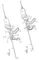
- Figure 1 is a perspective view of an ultrasonic device incorporating the catheter and probe of the present invention with the probe retracted into the catheter;
- Figure 2 is a perspective view of an ultrasonic device incorporating the catheter and probe of the present invention showing the probe extended from the catheter;
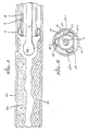
- Figure 3 is a sectional side view of an occluded blood vessel illustrating the breakup of plaque in conjunction with use of the present invention;
- Figure 4 is a sectional view looking into a catheter of the present invention having multiple lumens for the passage of the probe, the radiographic contrast fluid, and suction of plaque debris; and
- Figure 5 is a sectional side view of the catheter and probe tip of the present invention illustrating the flexible probe extension.
- The following description is of the best presently contemplated mode of carrying out the invention. This description is made for the purpose of illustrating the general principles of the invention and is not to be taken in a limiting sense. The scope of the invention is best determined by reference to the appended claims. "Artery" and "blood vessel" are used interchangeably to refer to blood vessels generally. Although the discussion refers primarily to the treatment of atherosclerosis, it is to be understood that the techniques and devices discussed also apply to the treatment of blood clots as well.
- Figure 1 shows a perspective view of a
catheter 8 andprobe 6 attached to anultrasonic power source 10 generating ultrasonic vibrations that are transmitted through the probe. The particularultrasonic power source 10 illustrated in Figure 1 may be of the type commonly used in conjunction with a probe inserted into the urethra for the treatment of calcified stones in the urinary tract. The exact configuration and method of generating ultrasonic vibrations is not critical to the present invention. Either continuous ultrasonic energy or pulsed ultrasonic energy may be used. - The ultrasonic power source includes a
support stock 12 which has asupport rack 14, anintegral grip 16, and atrigger 18. Attached at one end of the power source is anultrasonic vibration generator 20, to which is connected one end of themetal probe 6. Thevibration generator 20 uses electrical energy to produce ultrasonic vibrations by, for example, vibrating a crystal at ultrasonic frequencies. Connecting themetal probe 6 to thevibration generator 20 allows the ultrasonic vibrations of the crystal to be transmitted down the length of the probe. Thegenerator 20 is attached to a mountingbracket 30 having tworods 32 and 34 that are inserted into thestock 12. The probe is coupled to theultrasonic vibration generator 20 through avibration fitting 22 that is part of the mountingbracket 30. - The ultrasonic power source preferably makes the probe vibrate transversely as well as backward and forward. The dual transverse and longitudinal motion increases the efficiency of the ultrasonic energy in destroying the intravascular blockage. In accordance with techniques known in the art, the length of the probe may be selected for maximum energy efficiency and effectiveness of transverse and longitudinal probe movement. Specifically, the length of the probe is selected so as to be an acoustical length that is a whole number multiple of one-half the wavelength of the ultrasonic frequency in the material of which the probe is made, with the bulbous tip located at an antinode of the probe length. The antinodal point is the point at which longitudinal and transverse motions of the probe are at a peak, and therefore the probe tip will undergo both longitudinal and transverse motion. The movement of the probe has a peak-to-peak magnitude of approximately 40 microns.
- The ultrasonic movement of the probe serves to break up and dissolve the plaque in a chipping or beating action. In addition, movement of the probe creates bubbles and turbulence. The turbulence creates a cavitation action or increase in fluid pressure at the treatment site on the order of 2 to 3 atmospheres. This type of cavitation action works in concert with the chipping action to further break up the particles of plaque.
- The
probe 6 is preferably constructed of flexible metal wire, such as a cobalt nickel alloy, and is carried in thecatheter 8 such that the distal end of the probe is slightly recessed within the catheter. The probe passes through an irrigation fitting 24 that is attached to thestock 12. Attached to the fitting 24 is the catheter orsheath 8 that may be constructed, for example, of plastic. The irrigation fitting 24 includes afluid conduit 26. The conduit communicates with the catheter via an internal passageway (not illustrated) and in this way a radiographic contrast fluid may be introduced through theconduit 26 into the catheter. The contrast fluid presents a distinct image of the probe and blockage in an x-ray image, depending on concentration, and allows the treating physician to observe the location of the catheter and probe in the blood vessel while also monitoring the progress of the ultrasonic treatment in destroying the occlusion and improving the flow of blood in the blood vessel. The fluid conduit also may be used for aspiration (suction) of debris from the treatment site. Alternatively, more than one fluid conduit may be provided. For example, one conduit may be used for aspiration while another conduit may be used for contrast fluid. - Figure 2 shows a perspective view of the
ultrasonic device 10 illustrating theprobe 6 extended from thecatheter 8. Theultrasonic vibration generator 20 is attached to abracket 30 having tworods 32 and 34, which fit into cylindrical openings in thesupport stock 12. The forward end of thebracket 30 is coupled to thetrigger 18 such that pulling back on the trigger pulls thebracket 30 forward, carrying thevibration generator 20 with it. Since theprobe 6 is attached to thevibration generator 20 via thevibration fitting 22, pulling on the trigger causes the probe to slide forward with thegenerator 20. Because thecatheter 8 is attached to the fitting 24, which is attached to thestock 12 and does not move, thecatheter 8 remains stationary when theprobe 6 moves forward. The probe, which is normally co-extensive with or slightly recessed from the end of thecatheter 8, slides within the catheter and is thereby extended from the end of the catheter. - Figure 3 shows a sectional side view of the present invention in place in an occluded blood vessel. The interior surface of the
vessel wall 40 is shown with a mass ofplaque 42 deposited thereon. Thecatheter 8 andprobe 6 have been inserted upstream into the blood vessel and are located adjacent to theoccluded mass 42. Themetal probe 6 has been extended from thecatheter 8 so as to make contact with the plaque. Figure 3 shows that thetip 44 of the probe has a bulbous shape. This shape has been found to result in the rapid destruction of atherosclerotic plaque by efficiently transferring the ultrasonic energy while being free of any tendency to poking, tearing or perforating the healthy blood vessel wall. Thebulbous tip 44 of the probe is preferably slightly less in diameter than the inside diameter of the catheter, and therefore can be easily carried in the catheter to the treatment site. Because the probe is carried within a catheter to the sight of the stenosis, the probe needn't be rigid or stiff enough to be advanced independently in the blood vessel. Thus, the probe can be made flexible enough to prevent perforation of the blood vessel during treatment. - The probe vibrates generally at a fixed frequency, that frequency being in the range of 20,000 to 27,000 Hz. The vibration may be steady and continuous or it may be pulsed. Preferably, the pulsing has a 20 msec. cycle time, being on for 20 msec. and then off for 20 msec. The energy applied, in terms of watts, may also be varied. Generally, the sonic power from the probe will be in the range of 2 to 5 watts/cm², or between 5 and 50 total watts. As the
probe tip 44 vibrates ultrasonically, thetip 44 tends to become heated. As the probe vibrates it breaks up and pulverizes the plaque or clot but, if uncontrolled, the temperature of the tip could damage the adjacentblood vessel wall 40. Pulsing the vibration action, rather than using continuous energy, may help to reduce and control the tip temperature. From the relative size of thetip 44 andcatheter 8 illustrated in Figure 3, it is apparent that there is a space between thecatheter wall 8 and theprobe tip 44, as well as between the catheter wall and themetal probe 6. Physiologic solution introduced through theconduit 26 of the ultrasonic energy source can flow in this space through the catheter and directly to thetip 44 of the probe, thereby cooling the probe tip and providing a temperature regulating function. The arrows 46 show that the space between the probe and catheter can be used for the flow of fluid down the catheter and also for the aspiration of particles up the catheter. - The
catheter 8 may be provided with a cuff orannular balloon 9 around its outer circumference near its distal end. Aconduit 11 may be provided along the outside of the catheter or, alternatively, within the catheter or within the wall of the catheter, so as to provide air or fluid into the cuff and thereby inflate it. The cuff would remain deflated during the insertion procedure, and would be inflated once the catheter was located at the treatment site. Figure 3 shows thecuff 9 inflated out to thevessel wall 40, thereby centering thecatheter 8 in the blood vessel and blocking off the treatment site. By centering the catheter, theprobe 6 is also centered in the blood vessel. This helps to ensure that the probe will not veer off from the center axis of the blood vessel toward the vessel wall once the probe is extended from the catheter, and prevents the probe from perforating the vessel wall. Blocking off the treatment site also helps to prevent large debris particles from travelling backward in the blood vessel and helps to contain the radiographic contrast fluid at the treatment site. - Figure 4 shows a sectional view looking up a
catheter 60 having multiple passageways orlumens central passageway 62 is preferably provided for passage of theprobe 6, so that the probe is more likely to stay centered in the blood vessel and reduce the chance of perforation. An inner wall 62a forms thecentral passageway 62. Placed around the central passageway between it and the catheterinterior wall surface 60 are thepassageways wall passageway 63 may be used for carrying the radiographic contrast fluid, anotherpassageway 64 may be used for suction of plaque debris, and athird passageway 65 may be used for infusing physiologic solution. Other passageways may also be provided, as desired. Thus, the treatment site may be simultaneously flushed and aspirated by the passageways. The cross-sectional shape of the lumens may be of any shape desired and are not limited to semicircular shapes. - The multiple lumens may be provided as shown in Figure 4, with a central lumen within the
catheter 8 and other lumens provided between the central lumen and interior wall of the catheter, or the multiple lumens may be provided by multiple concentric walls within thecatheter 8. In either case, it is preferable that the central lumen or passageway in which the catheter is carried is also used for suction. This is desirable for two reasons. First, the central lumen is larger than the others, so that plaque debris will more easily be carried up the catheter without clogging if aspiration is performed. Second, the ultrasonic vibration travelling down the probe to the tip helps to further break up the debris being aspirated, further decreasing the likelihood of catheter clogging due to aspirated debris. - The multiple lumens will preferably be provided with an ultrasonic power source that includes multiple fluid conduits similar to the
conduit 26. Preferably, each lumen will communicate with a different fluid conduit, although this is not essential. The exact manner of communication between the catheter passageways and the source of fluid or suction is not critical to the present invention. - The apparatus of the present invention may be inserted in a blood vessel in a manner similar to that used in taking an angiogram. In the angiographic procedure, a local anesthetic is applied at a convenient location of the patient, such as at an arm or leg, after which an incision is made through the skin and down to a blood vessel. A self-sealing sheath is inserted into the blood vessel at the incision. A catheter may then be inserted through the sheath and upstream into the blood vessel, and may be advanced in the vessel to the treatment site, such as a peripheral or coronary artery. This procedure allows the use of a simple local anesthetic rather than a surgical procedure with general anesthesia. The self-sealing sheath prevents blood from leaking back out from the blood vessel during the treatment. Thus, the patient's circulation is not interrupted.
- Once introduced in the blood vessel, the catheter and probe may be passed to a particular site of interest by introducing radiographic contrast fluid into the blood vessel and viewing the real-time x-ray image of the catheter and probe within the artery on an x-ray monitor screen such as a fluoroscope. Preferably, the contrast fluid is released in the vessel at the time of catheter insertion to aid the physician in confirming that the catheter and probe are in the vessel and have not perforated the vessel wall.
- The contrast fluid presents a distinct image of the probe and intravascular blockage on the fluoroscope. This allows the physician to determine the location of the catheter and probe at any instant in time and to confirm that the probe is still contained within the blood vessel and that no perforation has occurred. The progress of the treatment also may be viewed by observing the flow of contrast fluid from the catheter into the artery. The treatment site should be aspirated to clean it of debris and the cuff should be deflated. Then, if the contrast fluid does not move downstream from the catheter, the stenosis is still present. The faster the progress of contrast fluid, the greater the extent of plaque destruction.
- In addition, a physiologic saline, anticoagulant or other physiologic solution may be introduced into the catheter, for example, to maintain the
probe tip 44 at the desired temperature. The probe tip is heated during the application of ultrasonic energy and, depending on the procedure used, the healthy blood vessel tissue near the probe tip could become damaged if the tip temperature was not controlled. The physiologic solution may be inserted into the blood vessel by replacing the contrast fluid in the hollow catheter, or the solution may be inserted by using one of the passageways in a catheter with multiple lumens rather than a single hollow bore. Ordinarily, pulsing of the ultrasonic power and modulation of the power level will be sufficient to control the temperature of the probe tip and prevent damage to healthy tissue without physiologic solution. - Figure 5 shows that the
bulbous tip 44 or "ball point" end of the probe may be provided with a thin, veryflexible extension 45 of 1 to 2 cm in length. The flexible extension is preferably not carried within the catheter. The floppy extension is flexible enough that it folds back on itself if it meets with an obstruction or vessel wall. In this way, the extension acts like a spring to divert the probe away from the wall or obstruction. The extension thereby helps to reduce the chance of blood vessel perforation while the probe and catheter are advanced in the blood vessel. Figure 5 shows that thefloppy extension 45 is smaller in diameter than that of the probe and the bulbous probe tip, and that the diameter of theprobe tip 44 is slightly less in diameter than the inside diameter of the catheter. In the blood vessel, theextension 45 would be folded back on itself during the application of ultrasonic energy. The magnitude and velocity of movement of theextension 45 would thereby be less than that of theprobe tip 44. - Thus, the procedure used with the apparatus of the present invention would be to first insert the self-sealing sheath and then the catheter carrying the probe into the blood vessel. Next, radiographic contrast fluid would be released through the catheter into the blood vessel, while observing the location of the catheter/probe combination on the x-ray or fluoroscope image. Once the end of the catheter is located at the site of occlusion, the
trigger 18 may be pulled back so as to extend theprobe 6 into the mass of plaque, whereupon ultrasonic energy may be applied through theprobe 6 to break up and disintegrate the plaque. If the catheter is provided with a cuff, the cuff would be inflated prior to applying ultrasonic energy. It may be unnecessary to draw off the particles by aspiration, or suction. If suction is desired, a catheter with multiple lumens may be provided, one of the lumens being used for the suction removal of debris. Because of the reduced chance of perforation, and due to the fact that contrast fluid is delivered to the site of treatment, ordinarily it is not necessary to have direct visual observation of the treatment site. - The bulbous, solid probe allows efficient transfer of ultrasonic energy, flexible probe construction, and reduced chance of blood vessel perforation. The flexible probe and bulbous tip efficiently transfer ultrasonic energy to the mass of accumulated deposits, thereby breaking up and pulverizing the mass. The flexibility of the probe reduces the chance of perforating the blood vessel wall as the probe tip is advanced into the accumulated mass.
Claims (20)
an ultrasonic energy source;
an elongated, solid, flexible probe having first and second ends and coupled at the first end to the ultrasonic energy source and having a tip at the second end, the probe length selected so as to provide both longitudinal and transverse motion of the probe tip, the probe tip having a bulbous shape such that the tip of the probe is rounded and has a diameter greater than that of the remainder of the probe; and
a hollow catheter for internally carrying a portion of the probe, the catheter having first and second ends; and
the probe is adapted to slide within the catheter and to be extendable from the second end of the catheter into a mass of atherosclerotic plaque or blood clots.
an ultrasonic energy source;
an elongated, solid, flexible probe; and
a hollow catheter having first and second ends, internally carrying a portion of the probe, the second end of the probe adapted to be inserted into the blood vessel to be treated; the catheter having an inflatable annular balloon around the outer circumference of the second end of the catheter.
a flexible, elongated metal wire probe having one end adapted to be coupled to the ultrasonic energy source and having a bulbous, rounded tip at the other end, and the length of the probe being selected so that the probe length is an acoustical length of a whole number multiple of a one-half wavelength of the frequency of the ultrasonic energy source in the material of which the probe is constructed, with the bulbous tip of the probe located at an antinode of the probe length;
a hollow catheter comprised of a flexible material having an inside diameter sufficient to internally carry the bulbous rounded tip of the probe, adapted to be inserted into the blood vessel at one end, and having an inflatable cuff at the inserted end that may be inflated to axially center the catheter and probe in the blood vessel; and
means, coupled to the catheter, for introducing fluid into the blood vessel through the catheter.
viewing the flow of contrast fluid released from the catheter into the blood vessel after the transmission of ultrasonic energy to determine the extent of destruction of the arterial blockage.
supplying a physiologic fluid through the catheter to the site of arterial blockage to control the temperature of the probe tip while the ultrasonic energy is being applied.
removing plaque debris from the area of the treatment site by creating a suction through the catheter.
removing plaque debris from the area of the treatment site by creating a suction through one of the internal passageways.
the step (d) of the method further includes inflating the annular cuff, thereby blocking off the treatment site and centering the catheter in the blood vessel.
removing plaque debris from the area of the treatment site by creating a suction through one of the internal passageways of the catheter.
the step (c) includes inflating the annular balloon so as to block off the treatment site and center the catheter in the blood vessel.
Applications Claiming Priority (2)
| Application Number | Priority Date | Filing Date | Title |
|---|---|---|---|
| US120390 | 1987-11-13 | ||
| US07/120,390 US4870953A (en) | 1987-11-13 | 1987-11-13 | Intravascular ultrasonic catheter/probe and method for treating intravascular blockage |
Publications (3)
| Publication Number | Publication Date |
|---|---|
| EP0316796A2 true EP0316796A2 (en) | 1989-05-24 |
| EP0316796A3 EP0316796A3 (en) | 1989-09-27 |
| EP0316796B1 EP0316796B1 (en) | 1994-11-30 |
Family
ID=22389963
Family Applications (1)
| Application Number | Title | Priority Date | Filing Date |
|---|---|---|---|
| EP88118819A Expired - Lifetime EP0316796B1 (en) | 1987-11-13 | 1988-11-11 | Intravascular ultrasonic catheter probe for treating intravascular blockage |
Country Status (5)
| Country | Link |
|---|---|
| US (1) | US4870953A (en) |
| EP (1) | EP0316796B1 (en) |
| JP (1) | JP2709358B2 (en) |
| CA (1) | CA1321241C (en) |
| DE (1) | DE3852275T2 (en) |
Cited By (48)
| Publication number | Priority date | Publication date | Assignee | Title |
|---|---|---|---|---|
| EP0401158A1 (en) * | 1989-06-01 | 1990-12-05 | Schneider (Europe) Ag | Catheter apparatus with a guide wire and method for the production of such a guide wire |
| DE3930600A1 (en) * | 1989-09-07 | 1991-04-04 | Schubert Werner | Expansible probe for blood vessel, etc. treatment - is used for pressure shock and coupling of wave energy imparting medium |
| DE4028518A1 (en) * | 1989-11-01 | 1991-05-02 | Olympus Optical Co | ULTRASONIC DIAGNOSTIC DEVICE |
| EP0443256A1 (en) * | 1990-01-23 | 1991-08-28 | Urcan Medical Limited | Ultrasonic recanalization system |
| DE4036570A1 (en) * | 1990-11-16 | 1992-05-21 | Osypka Peter | CATHETER FOR REDUCING OR REMOVING CONSTRUCTIONS IN VESSELS |
| WO1992011815A2 (en) * | 1991-01-11 | 1992-07-23 | Baxter International Inc. | Ultrasonic angioplasty device incorporating transmission member and ablation probe |
| EP0554616A2 (en) * | 1992-01-24 | 1993-08-11 | Scimed Life Systems, Inc. | Apparatus for intravascular cavitation or delivery of low frequency mechanical energy |
| US5267954A (en) * | 1991-01-11 | 1993-12-07 | Baxter International Inc. | Ultra-sound catheter for removing obstructions from tubular anatomical structures such as blood vessels |
| US5269291A (en) * | 1990-12-10 | 1993-12-14 | Coraje, Inc. | Miniature ultrasonic transducer for plaque ablation |
| WO1994001047A1 (en) * | 1992-07-10 | 1994-01-20 | Baxter International Inc. | Ultrasonic angioplasty and ablative devices for treating vasospasm |
| EP0582766A1 (en) * | 1992-08-13 | 1994-02-16 | Ministero Dell' Universita' E Della Ricerca Scientifica E Tecnologica | Ultrasonic recanalization system and transducer therefor |
| FR2696099A1 (en) * | 1992-05-19 | 1994-04-01 | Arizona Board Regents Behalf U | Apparatus for eliminating cardiac arrhythmias by intracardiac ablation and intracardiac catheter. |
| US5312328A (en) * | 1991-01-11 | 1994-05-17 | Baxter International Inc. | Ultra-sound catheter for removing obstructions from tubular anatomical structures such as blood vessels |
| US5342292A (en) * | 1991-11-04 | 1994-08-30 | Baxter International Inc. | Ultrasonic ablation device adapted for guidewire passage |
| US5368558A (en) * | 1991-01-11 | 1994-11-29 | Baxter International Inc. | Ultrasonic ablation catheter device having endoscopic component and method of using same |
| US5380274A (en) * | 1991-01-11 | 1995-01-10 | Baxter International Inc. | Ultrasound transmission member having improved longitudinal transmission properties |
| US5382228A (en) * | 1992-07-09 | 1995-01-17 | Baxter International Inc. | Method and device for connecting ultrasound transmission member (S) to an ultrasound generating device |
| US5390678A (en) * | 1993-10-12 | 1995-02-21 | Baxter International Inc. | Method and device for measuring ultrasonic activity in an ultrasound delivery system |
| US5405318A (en) * | 1992-05-05 | 1995-04-11 | Baxter International Inc. | Ultra-sound catheter for removing obstructions from tubular anatomical structures such as blood vessels |
| US5417672A (en) * | 1993-10-04 | 1995-05-23 | Baxter International Inc. | Connector for coupling an ultrasound transducer to an ultrasound catheter |
| US5427118A (en) * | 1993-10-04 | 1995-06-27 | Baxter International Inc. | Ultrasonic guidewire |
| EP0664686A1 (en) * | 1992-09-14 | 1995-08-02 | Coraje, Inc. | Apparatus and method for enhanced intravascular phonophoresis including dissolution of intravascular blockage and concomitant inhibition of restenosis |
| US5997497A (en) * | 1991-01-11 | 1999-12-07 | Advanced Cardiovascular Systems | Ultrasound catheter having integrated drug delivery system and methods of using same |
| WO2002002173A1 (en) * | 2000-06-30 | 2002-01-10 | Cedars Sinai Medical Center | Image guidance method coronary stent deployment |
| EP1182976A1 (en) * | 1999-10-05 | 2002-03-06 | Omnisonics Medical Technologies, Inc. | Ultrasonic medical device operating in a transverse mode |
| WO2002019927A1 (en) * | 2000-09-05 | 2002-03-14 | Calluna Ide Ab | Method and device for chemical dispersion of a gel in an organic structure |
| EP1365689A2 (en) * | 2001-02-02 | 2003-12-03 | Omnisonics Medical Technologies, Inc. | Method of removing occlusions using ultrasonic medical device operating in a transverse mode |
| US6689086B1 (en) | 1994-10-27 | 2004-02-10 | Advanced Cardiovascular Systems, Inc. | Method of using a catheter for delivery of ultrasonic energy and medicament |
| EP1500373A3 (en) * | 1999-10-05 | 2005-02-02 | Omnisonics Medical Technologies, Inc. | Ultrasonic medical device operating in a transverse mode |
| US6929632B2 (en) | 1991-01-11 | 2005-08-16 | Advanced Cardiovascular Systems, Inc. | Ultrasonic devices and methods for ablating and removing obstructive matter from anatomical passageways and blood vessels |
| WO2007136599A3 (en) * | 2006-05-16 | 2008-06-05 | Wilson Cook Medical Inc | Balloon cuff |
| WO2011157362A1 (en) * | 2010-06-16 | 2011-12-22 | Hpf Gmbh | Arrangement and method for removing thrombi |
| EP2449987A1 (en) * | 2003-01-14 | 2012-05-09 | Flowcardia Inc. | Ultrasound catheter and methods for making and using same |
| US9629643B2 (en) | 2006-11-07 | 2017-04-25 | Flowcardia, Inc. | Ultrasound catheter having improved distal end |
| US10004520B2 (en) | 2004-08-26 | 2018-06-26 | Flowcardia, Inc. | Ultrasound catheter devices and methods |
| US10111680B2 (en) | 2002-08-02 | 2018-10-30 | Flowcardia, Inc. | Therapeutic ultrasound system |
| US10130380B2 (en) | 2003-02-26 | 2018-11-20 | Flowcardia, Inc. | Ultrasound catheter apparatus |
| US10285719B2 (en) | 2005-01-20 | 2019-05-14 | Flowcardia, Inc. | Vibrational catheter devices and methods for making same |
| US10285727B2 (en) | 2002-08-26 | 2019-05-14 | Flowcardia, Inc. | Steerable ultrasound catheter |
| US10349964B2 (en) | 2003-09-19 | 2019-07-16 | Flowcardia, Inc. | Connector for securing ultrasound catheter to transducer |
| US10357263B2 (en) | 2012-01-18 | 2019-07-23 | C. R. Bard, Inc. | Vascular re-entry device |
| US10376272B2 (en) | 2002-08-26 | 2019-08-13 | Flowcardia, Inc. | Ultrasound catheter for disrupting blood vessel obstructions |
| US10582983B2 (en) | 2017-02-06 | 2020-03-10 | C. R. Bard, Inc. | Ultrasonic endovascular catheter with a controllable sheath |
| US10758256B2 (en) | 2016-12-22 | 2020-09-01 | C. R. Bard, Inc. | Ultrasonic endovascular catheter |
| US10835267B2 (en) | 2002-08-02 | 2020-11-17 | Flowcardia, Inc. | Ultrasound catheter having protective feature against breakage |
| US11344750B2 (en) | 2012-08-02 | 2022-05-31 | Flowcardia, Inc. | Ultrasound catheter system |
| US11596726B2 (en) | 2016-12-17 | 2023-03-07 | C.R. Bard, Inc. | Ultrasound devices for removing clots from catheters and related methods |
| US11633206B2 (en) | 2016-11-23 | 2023-04-25 | C.R. Bard, Inc. | Catheter with retractable sheath and methods thereof |
Families Citing this family (293)
| Publication number | Priority date | Publication date | Assignee | Title |
|---|---|---|---|---|
| RU2050152C1 (en) * | 1986-11-27 | 1995-12-20 | Сумимото Бейклайт Компани Лимитед | Ultrasonic surgical apparatus |
| GB8829182D0 (en) | 1988-12-14 | 1989-01-25 | Univ Birmingham | Surgical instrument |
| US5425735A (en) * | 1989-02-22 | 1995-06-20 | Psi Medical Products, Inc. | Shielded tip catheter for lithotripsy |
| WO1990009762A1 (en) * | 1989-02-22 | 1990-09-07 | Physical Sciences Inc. | Acoustic impact delivery catheter with end cap |
| US5246447A (en) * | 1989-02-22 | 1993-09-21 | Physical Sciences, Inc. | Impact lithotripsy |
| US4936281A (en) * | 1989-04-13 | 1990-06-26 | Everest Medical Corporation | Ultrasonically enhanced RF ablation catheter |
| US5092872A (en) * | 1989-07-28 | 1992-03-03 | Jacob Segalowitz | Valvulotome catheter |
| US5399158A (en) * | 1990-05-31 | 1995-03-21 | The United States Of America As Represented By The Secretary Of The Army | Method of lysing thrombi |
| US5279546A (en) * | 1990-06-27 | 1994-01-18 | Lake Region Manufacturing Company, Inc. | Thrombolysis catheter system |
| US5354324A (en) * | 1990-10-18 | 1994-10-11 | The General Hospital Corporation | Laser induced platelet inhibition |
| US5053008A (en) * | 1990-11-21 | 1991-10-01 | Sandeep Bajaj | Intracardiac catheter |
| US5368557A (en) * | 1991-01-11 | 1994-11-29 | Baxter International Inc. | Ultrasonic ablation catheter device having multiple ultrasound transmission members |
| US5447509A (en) * | 1991-01-11 | 1995-09-05 | Baxter International Inc. | Ultrasound catheter system having modulated output with feedback control |
| US5542917A (en) * | 1991-01-11 | 1996-08-06 | Baxter International, Inc. | Ultrasound delivery catheters incorporating improved distal tip construction |
| GB9107296D0 (en) * | 1991-04-08 | 1991-05-22 | Clinical Product Dev Ltd | Surgical device |
| US5480379A (en) * | 1991-05-22 | 1996-01-02 | La Rosa; Antonio | Ultrasonic dissector and detacher for atherosclerotic plaque and method of using same |
| US6497709B1 (en) | 1992-03-31 | 2002-12-24 | Boston Scientific Corporation | Metal medical device |
| US7101392B2 (en) | 1992-03-31 | 2006-09-05 | Boston Scientific Corporation | Tubular medical endoprostheses |
| JPH07505316A (en) | 1992-03-31 | 1995-06-15 | ボストン サイエンティフィック コーポレーション | medical wire |
| EP0820728B1 (en) | 1992-05-05 | 2000-09-13 | Advanced Cardiovascular Systems, Inc. | Ultrasonic angioplasty catheter device |
| US5713848A (en) | 1993-05-19 | 1998-02-03 | Dubrul; Will R. | Vibrating catheter |
| US5380273A (en) * | 1992-05-19 | 1995-01-10 | Dubrul; Will R. | Vibrating catheter |
| US6936025B1 (en) | 1992-05-19 | 2005-08-30 | Bacchus Vascular, Inc. | Thrombolysis device |
| WO1994006510A1 (en) * | 1992-09-11 | 1994-03-31 | Advanced Surgical, Inc. | Self-introducing infusion catheter |
| US5397293A (en) * | 1992-11-25 | 1995-03-14 | Misonix, Inc. | Ultrasonic device with sheath and transverse motion damping |
| CA2150707A1 (en) * | 1992-12-01 | 1994-06-09 | Mir A. Imram | Vibratory element for crossing stenoses |
| US5630840A (en) | 1993-01-19 | 1997-05-20 | Schneider (Usa) Inc | Clad composite stent |
| US5366454A (en) * | 1993-03-17 | 1994-11-22 | La Corporation De L'ecole Polytechnique | Implantable medication dispensing device |
| US5449370A (en) * | 1993-05-12 | 1995-09-12 | Ethicon, Inc. | Blunt tipped ultrasonic trocar |
| US5547469A (en) * | 1994-05-13 | 1996-08-20 | Boston Scientific Corporation | Apparatus for performing diagnostic and therapeutic modalities in the biliary tree |
| US5527273A (en) * | 1994-10-06 | 1996-06-18 | Misonix, Inc. | Ultrasonic lipectomy probe and method for manufacture |
| US5836940A (en) * | 1994-10-25 | 1998-11-17 | Latis, Inc. | Photoacoustic drug delivery |
| US5817144A (en) * | 1994-10-25 | 1998-10-06 | Latis, Inc. | Method for contemporaneous application OF laser energy and localized pharmacologic therapy |
| US5509417A (en) | 1994-12-19 | 1996-04-23 | Hewlett Packard Company | Method and apparatus for phased array coupling ultrasonic energy into an acoustic waveguide wire |
| DE19504260A1 (en) * | 1995-02-09 | 1996-09-12 | Krieg Gunther | Catheter for enlarging narrowed arteries |
| DE19504261A1 (en) * | 1995-02-09 | 1996-09-12 | Krieg Gunther | Angioplasty catheter for dilating and / or opening blood vessels |
| US6176842B1 (en) * | 1995-03-08 | 2001-01-23 | Ekos Corporation | Ultrasound assembly for use with light activated drugs |
| US6210356B1 (en) | 1998-08-05 | 2001-04-03 | Ekos Corporation | Ultrasound assembly for use with a catheter |
| US5725494A (en) * | 1995-11-30 | 1998-03-10 | Pharmasonics, Inc. | Apparatus and methods for ultrasonically enhanced intraluminal therapy |
| US5735811A (en) * | 1995-11-30 | 1998-04-07 | Pharmasonics, Inc. | Apparatus and methods for ultrasonically enhanced fluid delivery |
| US5728062A (en) * | 1995-11-30 | 1998-03-17 | Pharmasonics, Inc. | Apparatus and methods for vibratory intraluminal therapy employing magnetostrictive transducers |
| US5813998A (en) * | 1996-02-28 | 1998-09-29 | Hewlett-Packard Company | Method and system for coupling acoustic energy using an end-fire array |
| US5713916A (en) * | 1996-02-28 | 1998-02-03 | Hewlett Packard Company | Method and system for coupling acoustic energy using shear waves |
| FR2747909B1 (en) * | 1996-04-26 | 1998-12-11 | Tran Khanh Vien | FILMED ULTRASONIC PROBE WITH DIAMOND PROBE HEAD FOR ULTRASONIC ANGIOPLASTY |
| US5746756A (en) * | 1996-06-03 | 1998-05-05 | Ethicon Endo-Surgery, Inc. | Internal ultrasonic tip amplifier |
| US5830127A (en) * | 1996-08-05 | 1998-11-03 | Cybersonics, Inc. | Method and apparatus for cleaning endoscopes and the like |
| US5971949A (en) | 1996-08-19 | 1999-10-26 | Angiosonics Inc. | Ultrasound transmission apparatus and method of using same |
| US6241703B1 (en) | 1996-08-19 | 2001-06-05 | Angiosonics Inc. | Ultrasound transmission apparatus having a tip |
| US6464660B2 (en) | 1996-09-05 | 2002-10-15 | Pharmasonics, Inc. | Balloon catheters having ultrasonically driven interface surfaces and methods for their use |
| US5846218A (en) | 1996-09-05 | 1998-12-08 | Pharmasonics, Inc. | Balloon catheters having ultrasonically driven interface surfaces and methods for their use |
| US6083232A (en) * | 1996-09-27 | 2000-07-04 | Advanced Cardivascular Systems, Inc. | Vibrating stent for opening calcified lesions |
| US5989274A (en) | 1996-10-17 | 1999-11-23 | Ethicon Endo-Surgery, Inc. | Methods and devices for improving blood flow to a heart of a patient |
| US6221038B1 (en) | 1996-11-27 | 2001-04-24 | Pharmasonics, Inc. | Apparatus and methods for vibratory intraluminal therapy employing magnetostrictive transducers |
| US6051010A (en) * | 1996-12-23 | 2000-04-18 | Ethicon Endo-Surgery, Inc. | Methods and devices for joining transmission components |
| US5776155A (en) * | 1996-12-23 | 1998-07-07 | Ethicon Endo-Surgery, Inc. | Methods and devices for attaching and detaching transmission components |
| US5873844A (en) * | 1997-01-22 | 1999-02-23 | Campero; Manuel | Method and apparatus for numbing tissue before inserting a needle |
| US5810859A (en) * | 1997-02-28 | 1998-09-22 | Ethicon Endo-Surgery, Inc. | Apparatus for applying torque to an ultrasonic transmission component |
| US5968060A (en) * | 1997-02-28 | 1999-10-19 | Ethicon Endo-Surgery, Inc. | Ultrasonic interlock and method of using the same |
| US5989275A (en) * | 1997-02-28 | 1999-11-23 | Ethicon Endo-Surgery, Inc. | Damping ultrasonic transmission components |
| US5957943A (en) * | 1997-03-05 | 1999-09-28 | Ethicon Endo-Surgery, Inc. | Method and devices for increasing ultrasonic effects |
| US6582392B1 (en) | 1998-05-01 | 2003-06-24 | Ekos Corporation | Ultrasound assembly for use with a catheter |
| US6723063B1 (en) * | 1998-06-29 | 2004-04-20 | Ekos Corporation | Sheath for use with an ultrasound element |
| WO1998048711A1 (en) * | 1997-05-01 | 1998-11-05 | Ekos Corporation | Ultrasound catheter |
| US6676626B1 (en) | 1998-05-01 | 2004-01-13 | Ekos Corporation | Ultrasound assembly with increased efficacy |
| ZA984222B (en) | 1997-05-19 | 1999-05-19 | Angiosonics Inc | Feedback control system for ultrasound probe |
| JP2002515812A (en) | 1997-05-19 | 2002-05-28 | アンジオソニックス インコーポレイテッド | Cooling system for ultrasonic equipment |
| US5931805A (en) * | 1997-06-02 | 1999-08-03 | Pharmasonics, Inc. | Catheters comprising bending transducers and methods for their use |
| US6228046B1 (en) | 1997-06-02 | 2001-05-08 | Pharmasonics, Inc. | Catheters comprising a plurality of oscillators and methods for their use |
| US5938633A (en) * | 1997-07-09 | 1999-08-17 | Ethicon Endo-Surgery, Inc. | Ultrasonic surgical devices |
| US6007514A (en) * | 1997-09-30 | 1999-12-28 | Nita; Henry | Ultrasound system with pathfinding guidewire |
| US5865748A (en) * | 1998-01-16 | 1999-02-02 | Guidant Corporation | Guided directional coronary atherectomy distal linear encoder |
| JP2002502804A (en) | 1998-02-10 | 2002-01-29 | アンジオソニックス インコーポレイテッド | Apparatus and method for suppressing restenosis by applying ultrasonic energy with a drug |
| US6482217B1 (en) | 1998-04-10 | 2002-11-19 | Endicor Medical, Inc. | Neuro thrombectomy catheter |
| US6666874B2 (en) | 1998-04-10 | 2003-12-23 | Endicor Medical, Inc. | Rotational atherectomy system with serrated cutting tip |
| US6001112A (en) * | 1998-04-10 | 1999-12-14 | Endicor Medical, Inc. | Rotational atherectomy device |
| FR2779933B1 (en) | 1998-06-23 | 2000-10-13 | Khanh Vien Tran | INTEGRATED TRANSLUMINAL ANGIOPLASTY CATHETER COMBINING A VASCULAR STENT DELIVERY SYSTEM AND AN ATHERECTOMY SYSTEM |
| US6312402B1 (en) | 1998-09-24 | 2001-11-06 | Ekos Corporation | Ultrasound catheter for improving blood flow to the heart |
| US6135976A (en) * | 1998-09-25 | 2000-10-24 | Ekos Corporation | Method, device and kit for performing gene therapy |
| US6149596A (en) * | 1998-11-05 | 2000-11-21 | Bancroft; Michael R. | Ultrasonic catheter apparatus and method |
| AU1128600A (en) | 1998-11-20 | 2000-06-13 | Joie P. Jones | Methods for selectively dissolving and removing materials using ultra-high frequency ultrasound |
| US6264630B1 (en) | 1998-12-23 | 2001-07-24 | Scimed Life Systems, Inc. | Balloon catheter having an oscillating tip configuration |
| US6767353B1 (en) | 2002-03-01 | 2004-07-27 | Samuel Shiber | Thrombectomy catheter |
| US8506519B2 (en) * | 1999-02-16 | 2013-08-13 | Flowcardia, Inc. | Pre-shaped therapeutic catheter |
| US20040024393A1 (en) * | 2002-08-02 | 2004-02-05 | Henry Nita | Therapeutic ultrasound system |
| US6617760B1 (en) | 1999-03-05 | 2003-09-09 | Cybersonics, Inc. | Ultrasonic resonator |
| EP1400204A1 (en) | 1999-08-05 | 2004-03-24 | Broncus Technologies, Inc. | Methods and devices for creating collateral channels in the lungs |
| US6749606B2 (en) | 1999-08-05 | 2004-06-15 | Thomas Keast | Devices for creating collateral channels |
| US7462162B2 (en) | 2001-09-04 | 2008-12-09 | Broncus Technologies, Inc. | Antiproliferative devices for maintaining patency of surgically created channels in a body organ |
| US7815590B2 (en) | 1999-08-05 | 2010-10-19 | Broncus Technologies, Inc. | Devices for maintaining patency of surgically created channels in tissue |
| US7022088B2 (en) | 1999-08-05 | 2006-04-04 | Broncus Technologies, Inc. | Devices for applying energy to tissue |
| US7175644B2 (en) | 2001-02-14 | 2007-02-13 | Broncus Technologies, Inc. | Devices and methods for maintaining collateral channels in tissue |
| US7422563B2 (en) | 1999-08-05 | 2008-09-09 | Broncus Technologies, Inc. | Multifunctional tip catheter for applying energy to tissue and detecting the presence of blood flow |
| US6712812B2 (en) | 1999-08-05 | 2004-03-30 | Broncus Technologies, Inc. | Devices for creating collateral channels |
| US7713279B2 (en) | 2000-12-20 | 2010-05-11 | Fox Hollow Technologies, Inc. | Method and devices for cutting tissue |
| US7708749B2 (en) | 2000-12-20 | 2010-05-04 | Fox Hollow Technologies, Inc. | Debulking catheters and methods |
| US6299622B1 (en) | 1999-08-19 | 2001-10-09 | Fox Hollow Technologies, Inc. | Atherectomy catheter with aligned imager |
| US8328829B2 (en) | 1999-08-19 | 2012-12-11 | Covidien Lp | High capacity debulking catheter with razor edge cutting window |
| US20050096669A1 (en) * | 1999-10-05 | 2005-05-05 | Omnisonics Medical Technologies, Inc. | Apparatus and method for an ultrasonic medical device to treat coronary thrombus bearing lesions |
| US6695782B2 (en) | 1999-10-05 | 2004-02-24 | Omnisonics Medical Technologies, Inc. | Ultrasonic probe device with rapid attachment and detachment means |
| US20040097996A1 (en) * | 1999-10-05 | 2004-05-20 | Omnisonics Medical Technologies, Inc. | Apparatus and method of removing occlusions using an ultrasonic medical device operating in a transverse mode |
| US20050043629A1 (en) * | 1999-10-05 | 2005-02-24 | Omnisonics Medical Technologies, Inc. | Apparatus and method for an ultrasonic medical device having a probe with a small proximal end |
| US20030065263A1 (en) * | 1999-10-05 | 2003-04-03 | Omnisonics Medical Technologies, Inc. | Ultrasonic probe device with rapid attachment and detachment means having a line contact collet |
| US6660013B2 (en) | 1999-10-05 | 2003-12-09 | Omnisonics Medical Technologies, Inc. | Apparatus for removing plaque from blood vessels using ultrasonic energy |
| US6733451B2 (en) * | 1999-10-05 | 2004-05-11 | Omnisonics Medical Technologies, Inc. | Apparatus and method for an ultrasonic probe used with a pharmacological agent |
| US20050043753A1 (en) * | 1999-10-05 | 2005-02-24 | Omnisonics Medical Technologies, Inc. | Apparatus and method for an ultrasonic medical device to treat peripheral artery disease |
| US20030236539A1 (en) * | 1999-10-05 | 2003-12-25 | Omnisonics Medical Technologies, Inc. | Apparatus and method for using an ultrasonic probe to clear a vascular access device |
| US6524251B2 (en) * | 1999-10-05 | 2003-02-25 | Omnisonics Medical Technologies, Inc. | Ultrasonic device for tissue ablation and sheath for use therewith |
| US20050119679A1 (en) * | 1999-10-05 | 2005-06-02 | Omnisonics Medical Technologies, Inc. | Apparatus and method for an ultrasonic medical device to treat chronic total occlusions |
| US6589253B1 (en) | 1999-12-30 | 2003-07-08 | Advanced Cardiovascular Systems, Inc. | Ultrasonic angioplasty transmission wire |
| US6450975B1 (en) | 1999-12-30 | 2002-09-17 | Advanced Cardiovascular Systems, Inc. | Ultrasonic transmission guide wire |
| US6508781B1 (en) | 1999-12-30 | 2003-01-21 | Advanced Cardiovascular Systems, Inc. | Ultrasonic ablation catheter transmission wire connector assembly |
| US6494891B1 (en) | 1999-12-30 | 2002-12-17 | Advanced Cardiovascular Systems, Inc. | Ultrasonic angioplasty transmission member |
| ES2282246T3 (en) | 2000-03-10 | 2007-10-16 | Anthony T. Don Michael | VASCULAR EMBOLIA PREVENTION DEVICE USING FILTERS. |
| US6638239B1 (en) | 2000-04-14 | 2003-10-28 | Glaukos Corporation | Apparatus and method for treating glaucoma |
| US7867186B2 (en) | 2002-04-08 | 2011-01-11 | Glaukos Corporation | Devices and methods for treatment of ocular disorders |
| ES2436668T3 (en) | 2000-12-20 | 2014-01-03 | Covidien Lp | Catheter to remove atheromatous or thrombotic occlusive material |
| US6647755B2 (en) | 2001-03-07 | 2003-11-18 | Omnisonics Medical Technologies, Inc. | Method for manufacturing small diameter medical devices |
| US20040243175A1 (en) * | 2001-03-12 | 2004-12-02 | Don Michael T. Anthony | Vascular obstruction removal system and method |
| DE60224421D1 (en) | 2001-03-28 | 2008-02-14 | Cybersonics Inc | PROBE FOR ULTRASOUND TRANSFORMER |
| US7387612B2 (en) * | 2001-03-28 | 2008-06-17 | Cybersonics, Inc. | Floating probe for ultrasonic transducers |
| ES2304438T3 (en) | 2001-04-07 | 2008-10-16 | Glaukos Corporation | GLAUCOMA STENT FOR THE TREATMENT OF GLAUCOMA. |
| US7678065B2 (en) | 2001-05-02 | 2010-03-16 | Glaukos Corporation | Implant with intraocular pressure sensor for glaucoma treatment |
| AU2002305400A1 (en) * | 2001-05-03 | 2002-11-18 | Glaukos Corporation | Medical device and methods of use for glaucoma treatment |
| US7331984B2 (en) | 2001-08-28 | 2008-02-19 | Glaukos Corporation | Glaucoma stent for treating glaucoma and methods of use |
| US7708712B2 (en) | 2001-09-04 | 2010-05-04 | Broncus Technologies, Inc. | Methods and devices for maintaining patency of surgically created channels in a body organ |
| US20030050662A1 (en) * | 2001-09-07 | 2003-03-13 | Don Michael T. Anthony | Devices for observing and treating body passages |
| DE10146011A1 (en) * | 2001-09-19 | 2003-04-03 | Klaus Zimmermann | Method for destruction of a thrombus in a blood vessel by use of ultrasonic vibrations transmitted to a vibration head via an ultrasonic wave-guide from a generator |
| US20040019318A1 (en) * | 2001-11-07 | 2004-01-29 | Wilson Richard R. | Ultrasound assembly for use with a catheter |
| US6989891B2 (en) | 2001-11-08 | 2006-01-24 | Optiscan Biomedical Corporation | Device and method for in vitro determination of analyte concentrations within body fluids |
| DE60209799T2 (en) | 2001-12-03 | 2007-01-25 | Ekos Corp., Bothell | CATHETER WITH SEVERAL ULTRASOUND EMITTING PARTS |
| DE60213457T2 (en) | 2001-12-03 | 2007-10-18 | Ekos Corp., Bothell | ULTRASONIC CATHETER FOR SMALL VESSELS |
| US20030163147A1 (en) * | 2002-02-22 | 2003-08-28 | Rabiner Robert A. | Apparatus and method for using a vascular introducer with an ultrasonic probe |
| US20040068189A1 (en) | 2002-02-28 | 2004-04-08 | Wilson Richard R. | Ultrasound catheter with embedded conductors |
| US8226629B1 (en) * | 2002-04-01 | 2012-07-24 | Ekos Corporation | Ultrasonic catheter power control |
| US8133236B2 (en) | 2006-11-07 | 2012-03-13 | Flowcardia, Inc. | Ultrasound catheter having protective feature against breakage |
| US7220233B2 (en) * | 2003-04-08 | 2007-05-22 | Flowcardia, Inc. | Ultrasound catheter devices and methods |
| US6921371B2 (en) | 2002-10-14 | 2005-07-26 | Ekos Corporation | Ultrasound radiating members for catheter |
| US6730048B1 (en) * | 2002-12-23 | 2004-05-04 | Omnisonics Medical Technologies, Inc. | Apparatus and method for ultrasonic medical device with improved visibility in imaging procedures |
| US20040176686A1 (en) * | 2002-12-23 | 2004-09-09 | Omnisonics Medical Technologies, Inc. | Apparatus and method for ultrasonic medical device with improved visibility in imaging procedures |
| EP1583569A4 (en) | 2003-01-03 | 2009-05-06 | Ekos Corp | Ultrasonic catheter with axial energy field |
| US8142457B2 (en) * | 2003-03-26 | 2012-03-27 | Boston Scientific Scimed, Inc. | Percutaneous transluminal endarterectomy |
| US8083707B2 (en) * | 2003-04-17 | 2011-12-27 | Tosaya Carol A | Non-contact damage-free ultrasonic cleaning of implanted or natural structures having moving parts and located in a living body |
| US8246640B2 (en) | 2003-04-22 | 2012-08-21 | Tyco Healthcare Group Lp | Methods and devices for cutting tissue at a vascular location |
| EP1619995A2 (en) | 2003-04-22 | 2006-02-01 | Ekos Corporation | Ultrasound enhanced central venous catheter |
| US8002740B2 (en) | 2003-07-18 | 2011-08-23 | Broncus Technologies, Inc. | Devices for maintaining patency of surgically created channels in tissue |
| US8308682B2 (en) | 2003-07-18 | 2012-11-13 | Broncus Medical Inc. | Devices for maintaining patency of surgically created channels in tissue |
| LT5248B (en) | 2003-09-16 | 2005-08-25 | Kauno technologijos universitetas | Ultrasonic catheter |
| US20080051660A1 (en) * | 2004-01-16 | 2008-02-28 | The University Of Houston System | Methods and apparatuses for medical imaging |
| CA2553165A1 (en) | 2004-01-29 | 2005-08-11 | Ekos Corporation | Method and apparatus for detecting vascular conditions with a catheter |
| EP1713393A1 (en) | 2004-02-09 | 2006-10-25 | Omnisonics Medical Technologies, Inc. | Apparatus and method for an ultrasonic medical device operating in a torsional mode |
| WO2005084552A1 (en) | 2004-02-09 | 2005-09-15 | Omnisonics Medical Technologies, Inc. | Apparatus and method for an ultrasonic medical device operating in torsional and transverse modes |
| US7794414B2 (en) | 2004-02-09 | 2010-09-14 | Emigrant Bank, N.A. | Apparatus and method for an ultrasonic medical device operating in torsional and transverse modes |
| US7686825B2 (en) | 2004-03-25 | 2010-03-30 | Hauser David L | Vascular filter device |
| US8409167B2 (en) | 2004-07-19 | 2013-04-02 | Broncus Medical Inc | Devices for delivering substances through an extra-anatomic opening created in an airway |
| US20060058837A1 (en) * | 2004-09-10 | 2006-03-16 | Arani Bose | System and method for treating ischemic stroke |
| US7931659B2 (en) * | 2004-09-10 | 2011-04-26 | Penumbra, Inc. | System and method for treating ischemic stroke |
| US9655633B2 (en) | 2004-09-10 | 2017-05-23 | Penumbra, Inc. | System and method for treating ischemic stroke |
| US20060100547A1 (en) * | 2004-10-27 | 2006-05-11 | Omnisonics Medical Technologies, Inc. | Apparatus and method for using an ultrasonic medical device to reinforce bone |
| WO2006060492A2 (en) * | 2004-12-01 | 2006-06-08 | Ethicon Endo-Surgery, Inc. | Ultrasonic device and method for treating stones within the body |
| WO2006063199A2 (en) | 2004-12-09 | 2006-06-15 | The Foundry, Inc. | Aortic valve repair |
| US7364562B2 (en) * | 2005-10-06 | 2008-04-29 | Optiscan Biomedical Corp. | Anti-clotting apparatus and methods for fluid handling system |
| WO2007030422A2 (en) * | 2005-09-06 | 2007-03-15 | Omnisonics Medical Technologies, Inc. | Ultrasound medical devices, systems and methods |
| US20080039728A1 (en) * | 2006-03-09 | 2008-02-14 | Dharmendra Pal | Catheters and Related Systems and Methods |
| US9282984B2 (en) | 2006-04-05 | 2016-03-15 | Flowcardia, Inc. | Therapeutic ultrasound system |
| EP2016402A2 (en) | 2006-04-11 | 2009-01-21 | Optiscan Biomedical Corporation | Anti-clotting apparatus and methods for fluid handling system |
| WO2007127176A2 (en) | 2006-04-24 | 2007-11-08 | Ekos Corporation | Ultrasound therapy system |
| WO2007127255A2 (en) | 2006-04-26 | 2007-11-08 | Illuminoss Medical, Inc. | Apparatus and methods for reinforcing bone |
| US7806900B2 (en) | 2006-04-26 | 2010-10-05 | Illuminoss Medical, Inc. | Apparatus and methods for delivery of reinforcing materials to bone |
| US20080154181A1 (en) * | 2006-05-05 | 2008-06-26 | Khanna Rohit K | Central nervous system ultrasonic drain |
| US20070276419A1 (en) | 2006-05-26 | 2007-11-29 | Fox Hollow Technologies, Inc. | Methods and devices for rotating an active element and an energy emitter on a catheter |
| US20080097251A1 (en) * | 2006-06-15 | 2008-04-24 | Eilaz Babaev | Method and apparatus for treating vascular obstructions |
| US20080200835A1 (en) * | 2006-06-30 | 2008-08-21 | Monson Gavin M | Energy Biopsy Device for Tissue Penetration and Hemostasis |
| GB0613979D0 (en) | 2006-07-13 | 2006-08-23 | Shturman Leonid | Rotational atherectomy device with solid support elements supported by fluid bearings |
| GB0623366D0 (en) * | 2006-11-23 | 2007-01-03 | Shturman Leonid | Rotational atherectomy device with fluid inflatable support elements and distal protection capability |
| GB0613981D0 (en) * | 2006-07-13 | 2006-08-23 | Shturman Leonid | |
| GB0613980D0 (en) | 2006-07-13 | 2006-08-23 | Shturman Leonid | Rotational Atherectomy Device with Fluid Inflatable Elements supported by Fluid Bearings |
| GB0613982D0 (en) | 2006-07-13 | 2006-08-23 | Shturman Leonid | Rotational atherectomy device with fluid inflatable support elements and two torque transmitting coils |
| KR100772902B1 (en) * | 2006-09-28 | 2007-11-05 | 삼성전자주식회사 | Semiconductor device and method of fabricating the same |
| US8192363B2 (en) | 2006-10-27 | 2012-06-05 | Ekos Corporation | Catheter with multiple ultrasound radiating members |
| US7879041B2 (en) | 2006-11-10 | 2011-02-01 | Illuminoss Medical, Inc. | Systems and methods for internal bone fixation |
| CA2668954C (en) | 2006-11-10 | 2020-09-08 | Glaukos Corporation | Uveoscleral shunt and methods for implanting same |
| EP2091445B1 (en) | 2006-11-10 | 2015-03-11 | Illuminoss Medical, Inc. | Systems for internal bone fixation |
| US7775994B2 (en) * | 2006-12-11 | 2010-08-17 | Emigrant Bank, N.A. | Ultrasound medical systems and related methods |
| US10182833B2 (en) | 2007-01-08 | 2019-01-22 | Ekos Corporation | Power parameters for ultrasonic catheter |
| ES2538110T3 (en) | 2007-01-08 | 2015-06-17 | Ekos Corporation | Power parameters for ultrasonic catheter |
| WO2008144575A2 (en) | 2007-05-18 | 2008-11-27 | Optiscan Biomedical Corporation | Fluid injection and safety system |
| US9044568B2 (en) | 2007-06-22 | 2015-06-02 | Ekos Corporation | Method and apparatus for treatment of intracranial hemorrhages |
| US9427289B2 (en) | 2007-10-31 | 2016-08-30 | Illuminoss Medical, Inc. | Light source |
| GB0722990D0 (en) | 2007-11-23 | 2008-01-02 | Shturman Leonid | Rotational atherectomy system with enhanced distal protection capability and method of use |
| JP2011505919A (en) | 2007-12-07 | 2011-03-03 | ゼヴェクス・インコーポレーテッド | Method for inducing lateral motion in Langevin type vibrators using split electrodes of ceramic elements |
| US8403968B2 (en) | 2007-12-26 | 2013-03-26 | Illuminoss Medical, Inc. | Apparatus and methods for repairing craniomaxillofacial bones using customized bone plates |
| CA2722370A1 (en) * | 2008-02-20 | 2009-08-27 | Mayo Foundation For Medical Education And Research | Systems, devices and methods for accessing body tissue |
| CA2715895A1 (en) * | 2008-02-20 | 2009-08-27 | Mayo Foundation For Medical Education And Research | Ultrasound guided systems and methods |
| US8784440B2 (en) | 2008-02-25 | 2014-07-22 | Covidien Lp | Methods and devices for cutting tissue |
| US20100010393A1 (en) * | 2008-07-08 | 2010-01-14 | Medtronic Vascular, Inc. | Treatment of Occlusions by External High Intensity Focused Ultrasound |
| KR101645754B1 (en) | 2008-10-13 | 2016-08-04 | 코비디엔 엘피 | Devices and methods for manipulating a catheter shaft |
| GB0905751D0 (en) | 2009-04-03 | 2009-05-20 | Shturman Leonid | Rotational atherectomy device with distal embolic protection and method of use |
| US8210729B2 (en) | 2009-04-06 | 2012-07-03 | Illuminoss Medical, Inc. | Attachment system for light-conducting fibers |
| US8512338B2 (en) | 2009-04-07 | 2013-08-20 | Illuminoss Medical, Inc. | Photodynamic bone stabilization systems and methods for reinforcing bone |
| WO2010126882A1 (en) | 2009-04-29 | 2010-11-04 | Fox Hollow Technologies, Inc. | Methods and devices for cutting and abrading tissue |
| RU2509538C2 (en) | 2009-05-14 | 2014-03-20 | ТАЙКО ХЕЛСКЕА ГРУП эЛПи | Cleanable atherectomy catheters and methods for using them |
| US8226566B2 (en) | 2009-06-12 | 2012-07-24 | Flowcardia, Inc. | Device and method for vascular re-entry |
| EP2448636B1 (en) | 2009-07-03 | 2014-06-18 | Ekos Corporation | Power parameters for ultrasonic catheter |
| AU2010328680B2 (en) | 2009-08-19 | 2014-10-23 | Illuminoss Medical, Inc. | Devices and methods for bone alignment, stabilization and distraction |
| WO2011068932A1 (en) | 2009-12-02 | 2011-06-09 | Fox Hollow Technologies, Inc. | Methods and devices for cutting tissue |
| JP5511107B2 (en) * | 2009-12-11 | 2014-06-04 | コヴィディエン リミテッド パートナーシップ | Substance removal device and method with improved substance capture efficiency |
| US9795404B2 (en) | 2009-12-31 | 2017-10-24 | Tenex Health, Inc. | System and method for minimally invasive ultrasonic musculoskeletal tissue treatment |
| US8740835B2 (en) | 2010-02-17 | 2014-06-03 | Ekos Corporation | Treatment of vascular occlusions using ultrasonic energy and microbubbles |
| KR101493138B1 (en) | 2010-06-14 | 2015-02-12 | 코비디엔 엘피 | Material removal device |
| US8684965B2 (en) | 2010-06-21 | 2014-04-01 | Illuminoss Medical, Inc. | Photodynamic bone stabilization and drug delivery systems |
| CN103228224B (en) | 2010-08-27 | 2015-11-25 | Ekos公司 | Be used for the treatment of the method and apparatus of intracranial hemorrhage |
| EP2621556B1 (en) | 2010-10-01 | 2020-06-10 | Zevex, Inc. | Method for improving accuracy in a peristaltic pump system based on tubing material properties |
| EP2632352B1 (en) | 2010-10-28 | 2017-04-12 | Covidien LP | Material removal device |
| CA2817213C (en) | 2010-11-11 | 2016-06-14 | Covidien Lp | Flexible debulking catheters with imaging and methods of use and manufacture |
| EP2654584A1 (en) | 2010-12-22 | 2013-10-30 | Illuminoss Medical, Inc. | Systems and methods for treating conditions and diseases of the spine |
| WO2012087842A1 (en) | 2010-12-23 | 2012-06-28 | The Foundry, Llc | System for mitral valve repair and replacement |
| US11458290B2 (en) | 2011-05-11 | 2022-10-04 | Ekos Corporation | Ultrasound system |
| US9345532B2 (en) | 2011-05-13 | 2016-05-24 | Broncus Medical Inc. | Methods and devices for ablation of tissue |
| US8709034B2 (en) | 2011-05-13 | 2014-04-29 | Broncus Medical Inc. | Methods and devices for diagnosing, monitoring, or treating medical conditions through an opening through an airway wall |
| JP5872692B2 (en) | 2011-06-21 | 2016-03-01 | トゥエルヴ, インコーポレイテッド | Artificial therapy device |
| US8936644B2 (en) | 2011-07-19 | 2015-01-20 | Illuminoss Medical, Inc. | Systems and methods for joint stabilization |
| JP2014533965A (en) | 2011-07-19 | 2014-12-18 | イルミンオス・メディカル・インコーポレイテッドIlluminOss Medical, Inc. | Apparatus and method for bone reconstruction and stabilization |
| WO2013033426A2 (en) | 2011-09-01 | 2013-03-07 | Covidien Lp | Catheter with helical drive shaft and methods of manufacture |
| EP4193907A1 (en) | 2011-09-13 | 2023-06-14 | Glaukos Corporation | Intraocular physiological sensor |
| US11202704B2 (en) | 2011-10-19 | 2021-12-21 | Twelve, Inc. | Prosthetic heart valve devices, prosthetic mitral valves and associated systems and methods |
| US9655722B2 (en) | 2011-10-19 | 2017-05-23 | Twelve, Inc. | Prosthetic heart valve devices, prosthetic mitral valves and associated systems and methods |
| CA3090422C (en) | 2011-10-19 | 2023-08-01 | Twelve, Inc. | Prosthetic heart valve devices, prosthetic mitral valves and associated systems and methods |
| US9763780B2 (en) | 2011-10-19 | 2017-09-19 | Twelve, Inc. | Devices, systems and methods for heart valve replacement |
| AU2012325809B2 (en) | 2011-10-19 | 2016-01-21 | Twelve, Inc. | Devices, systems and methods for heart valve replacement |
| US9039757B2 (en) | 2011-10-19 | 2015-05-26 | Twelve, Inc. | Prosthetic heart valve devices, prosthetic mitral valves and associated systems and methods |
| WO2013078235A1 (en) | 2011-11-23 | 2013-05-30 | Broncus Medical Inc | Methods and devices for diagnosing, monitoring, or treating medical conditions through an opening through an airway wall |
| US9579198B2 (en) | 2012-03-01 | 2017-02-28 | Twelve, Inc. | Hydraulic delivery systems for prosthetic heart valve devices and associated methods |
| JP6465490B2 (en) | 2012-03-26 | 2019-02-06 | グローコス コーポレーション | Implant delivery device |
| US9149291B2 (en) | 2012-06-11 | 2015-10-06 | Tenex Health, Inc. | Systems and methods for tissue treatment |
| US11406415B2 (en) | 2012-06-11 | 2022-08-09 | Tenex Health, Inc. | Systems and methods for tissue treatment |
| US8939977B2 (en) | 2012-07-10 | 2015-01-27 | Illuminoss Medical, Inc. | Systems and methods for separating bone fixation devices from introducer |
| US9532844B2 (en) | 2012-09-13 | 2017-01-03 | Covidien Lp | Cleaning device for medical instrument and method of use |
| WO2014055832A1 (en) | 2012-10-04 | 2014-04-10 | The University Of North Carolina At Chapel Hill | Methods and systems for using encapsulated microbubbles to process biological samples |
| KR101717387B1 (en) | 2012-11-08 | 2017-03-16 | 코비디엔 엘피 | Tissue-removing catheter including operational control mechanism |
| US9943329B2 (en) | 2012-11-08 | 2018-04-17 | Covidien Lp | Tissue-removing catheter with rotatable cutter |
| US8784434B2 (en) | 2012-11-20 | 2014-07-22 | Inceptus Medical, Inc. | Methods and apparatus for treating embolism |
| US9687281B2 (en) | 2012-12-20 | 2017-06-27 | Illuminoss Medical, Inc. | Distal tip for bone fixation devices |
| US9730638B2 (en) | 2013-03-13 | 2017-08-15 | Glaukos Corporation | Intraocular physiological sensor |
| US9878128B2 (en) | 2013-03-14 | 2018-01-30 | Boston Scientific Scimed, Inc. | Systems, apparatus and methods for treating blood vessels |
| CA2902713C (en) | 2013-03-14 | 2021-06-01 | Ekos Corporation | Method and apparatus for drug delivery to a target site |
| US9592151B2 (en) | 2013-03-15 | 2017-03-14 | Glaukos Corporation | Systems and methods for delivering an ocular implant to the suprachoroidal space within an eye |
| US10111747B2 (en) | 2013-05-20 | 2018-10-30 | Twelve, Inc. | Implantable heart valve devices, mitral valve repair devices and associated systems and methods |
| US10238406B2 (en) | 2013-10-21 | 2019-03-26 | Inari Medical, Inc. | Methods and apparatus for treating embolism |
| WO2015074038A1 (en) * | 2013-11-18 | 2015-05-21 | Jeremy Stigall | Methods and devices for thrombus dispersal with cooling element |
| US9782195B2 (en) | 2013-11-20 | 2017-10-10 | Board Of Regents Of The University Of Nebraska | Fluid jet arterial surgical device |
| US9788853B2 (en) | 2014-01-15 | 2017-10-17 | Cardio Flow, Inc. | Atherectomy devices and methods |
| US9456843B2 (en) | 2014-02-03 | 2016-10-04 | Covidien Lp | Tissue-removing catheter including angular displacement sensor |
| US9526519B2 (en) | 2014-02-03 | 2016-12-27 | Covidien Lp | Tissue-removing catheter with improved angular tissue-removing positioning within body lumen |
| WO2015200702A1 (en) | 2014-06-27 | 2015-12-30 | Covidien Lp | Cleaning device for catheter and catheter including the same |
| US9962181B2 (en) | 2014-09-02 | 2018-05-08 | Tenex Health, Inc. | Subcutaneous wound debridement |
| US10092742B2 (en) | 2014-09-22 | 2018-10-09 | Ekos Corporation | Catheter system |
| US10314667B2 (en) | 2015-03-25 | 2019-06-11 | Covidien Lp | Cleaning device for cleaning medical instrument |
| US9763689B2 (en) | 2015-05-12 | 2017-09-19 | Tenex Health, Inc. | Elongated needles for ultrasonic applications |
| WO2016201136A1 (en) | 2015-06-10 | 2016-12-15 | Ekos Corporation | Ultrasound catheter |
| US10292721B2 (en) | 2015-07-20 | 2019-05-21 | Covidien Lp | Tissue-removing catheter including movable distal tip |
| US10238490B2 (en) | 2015-08-21 | 2019-03-26 | Twelve, Inc. | Implant heart valve devices, mitral valve repair devices and associated systems and methods |
| US10314664B2 (en) | 2015-10-07 | 2019-06-11 | Covidien Lp | Tissue-removing catheter and tissue-removing element with depth stop |
| DK3364891T3 (en) | 2015-10-23 | 2023-10-02 | Inari Medical Inc | Device for intravascular treatment of vascular occlusion |
| CN116172753A (en) | 2016-04-29 | 2023-05-30 | 美敦力瓦斯科尔勒公司 | Prosthetic heart valve devices having tethered anchors and associated systems and methods |
| CN114588328A (en) | 2016-06-09 | 2022-06-07 | C·R·巴德股份有限公司 | System and method for correcting and preventing catheter occlusion |
| WO2018014021A2 (en) * | 2016-07-15 | 2018-01-18 | North Carolina State University | Ultrasound transducer and array for intravascular thrombolysis |
| CN106214216B (en) * | 2016-08-31 | 2019-01-25 | 赵萍萍 | A kind of thrombus removing instrument |
| EP3528717A4 (en) | 2016-10-24 | 2020-09-02 | Inari Medical, Inc. | Devices and methods for treating vascular occlusion |
| US10441312B2 (en) | 2017-02-23 | 2019-10-15 | Cardio Flow, Inc. | Atherectomy devices and methods |
| US11832877B2 (en) | 2017-04-03 | 2023-12-05 | Broncus Medical Inc. | Electrosurgical access sheath |
| US10433961B2 (en) | 2017-04-18 | 2019-10-08 | Twelve, Inc. | Delivery systems with tethers for prosthetic heart valve devices and associated methods |
| US10575950B2 (en) | 2017-04-18 | 2020-03-03 | Twelve, Inc. | Hydraulic systems for delivering prosthetic heart valve devices and associated methods |
| US10702378B2 (en) | 2017-04-18 | 2020-07-07 | Twelve, Inc. | Prosthetic heart valve device and associated systems and methods |
| US10792151B2 (en) | 2017-05-11 | 2020-10-06 | Twelve, Inc. | Delivery systems for delivering prosthetic heart valve devices and associated methods |
| US10646338B2 (en) | 2017-06-02 | 2020-05-12 | Twelve, Inc. | Delivery systems with telescoping capsules for deploying prosthetic heart valve devices and associated methods |
| US10709591B2 (en) | 2017-06-06 | 2020-07-14 | Twelve, Inc. | Crimping device and method for loading stents and prosthetic heart valves |
| US10786352B2 (en) | 2017-07-06 | 2020-09-29 | Twelve, Inc. | Prosthetic heart valve devices and associated systems and methods |
| US10729541B2 (en) | 2017-07-06 | 2020-08-04 | Twelve, Inc. | Prosthetic heart valve devices and associated systems and methods |
| AU2018328011B2 (en) | 2017-09-06 | 2022-09-15 | Inari Medical, Inc. | Hemostasis valves and methods of use |
| US11116625B2 (en) | 2017-09-28 | 2021-09-14 | Glaukos Corporation | Apparatus and method for controlling placement of intraocular implants |
| EP3691586A2 (en) | 2017-10-06 | 2020-08-12 | Glaukos Corporation | Systems and methods for delivering multiple ocular implants |
| USD846738S1 (en) | 2017-10-27 | 2019-04-23 | Glaukos Corporation | Implant delivery apparatus |
| US11154314B2 (en) | 2018-01-26 | 2021-10-26 | Inari Medical, Inc. | Single insertion delivery system for treating embolism and associated systems and methods |
| US11213314B1 (en) | 2018-05-24 | 2022-01-04 | Cardio Flow, Inc. | Atherectomy devices and methods |
| US11147582B2 (en) | 2018-06-14 | 2021-10-19 | Cardio Flow, Inc. | Atherectomy devices and methods |
| WO2019245746A1 (en) | 2018-06-21 | 2019-12-26 | Shockwave Medical, Inc. | System for treating occlusions in body lumens |
| EP3813696A4 (en) | 2018-06-27 | 2022-04-13 | IlluminOss Medical, Inc. | Systems and methods for bone stabilization and fixation |
| WO2020033260A1 (en) | 2018-08-07 | 2020-02-13 | Cardio Flow, Inc. | Atherectomy devices and methods |
| CA3114285A1 (en) | 2018-08-13 | 2020-02-20 | Inari Medical, Inc. | System for treating embolism and associated devices and methods |
| AU2020354380A1 (en) | 2019-09-24 | 2022-04-07 | Shockwave Medical, Inc. | System for treating thrombus in body lumens |
| CA3157521A1 (en) | 2019-10-16 | 2021-04-22 | Inari Medical, Inc. | Systems, devices, and methods for treating vascular occlusions |
| WO2022150631A1 (en) * | 2021-01-08 | 2022-07-14 | Hdl Therapeutics, Inc | Systems and methods for reducing low attenuation plaque and/or plaque burden in patients |
| WO2023055339A1 (en) * | 2021-09-28 | 2023-04-06 | Bard Peripheral Vascular, Inc. | Ultrasonic hypotube devices for treatment of ctos and stenotic lesions |
Citations (5)
| Publication number | Priority date | Publication date | Assignee | Title |
|---|---|---|---|---|
| US3433226A (en) * | 1965-07-21 | 1969-03-18 | Aeroprojects Inc | Vibratory catheterization apparatus and method of using |
| US3565062A (en) * | 1968-06-13 | 1971-02-23 | Ultrasonic Systems | Ultrasonic method and apparatus for removing cholesterol and other deposits from blood vessels and the like |
| US3809093A (en) * | 1972-04-14 | 1974-05-07 | S Abraham | Surgical tool |
| EP0189329A2 (en) * | 1985-01-25 | 1986-07-30 | Robert E. Fischell | A tunneling catheter system for transluminal arterial angioplasty |
| EP0234951A1 (en) * | 1986-02-28 | 1987-09-02 | Cardiovascular Imaging Systems, Inc. | Catheter apparatus |
Family Cites Families (18)
| Publication number | Priority date | Publication date | Assignee | Title |
|---|---|---|---|---|
| US3228400A (en) * | 1962-12-03 | 1966-01-11 | Thomas A Armao | Cryogenic capsule probes |
| US3369549A (en) * | 1965-10-05 | 1968-02-20 | Thomas A. Armao | Capsule probe having thermoelectric heat exchange means therein |
| US3517665A (en) * | 1967-06-28 | 1970-06-30 | Sheldon Edward E | Negative pressure treatment device |
| US3526219A (en) * | 1967-07-21 | 1970-09-01 | Ultrasonic Systems | Method and apparatus for ultrasonically removing tissue from a biological organism |
| NL145136C (en) * | 1967-07-25 | 1900-01-01 | ||
| US3496942A (en) * | 1968-03-01 | 1970-02-24 | Darrell R Shipley | Heater for internal use |
| US3861391A (en) * | 1972-07-02 | 1975-01-21 | Blackstone Corp | Apparatus for disintegration of urinary calculi |
| US3830240A (en) * | 1972-07-02 | 1974-08-20 | Blackstone Corp | Method and apparatus for disintegration of urinary calculi |
| US4375220A (en) * | 1980-05-09 | 1983-03-01 | Matvias Fredrick M | Microwave applicator with cooling mechanism for intracavitary treatment of cancer |
| US4431006A (en) * | 1982-01-07 | 1984-02-14 | Technicare Corporation | Passive ultrasound needle probe locator |
| CA1244889A (en) * | 1983-01-24 | 1988-11-15 | Kureha Chemical Ind Co Ltd | Device for hyperthermia |
| US4602633A (en) * | 1984-11-16 | 1986-07-29 | Blackstone Corporation | Methods and apparatus for disintegration of urinary calculi under direct vision |
| US4750902A (en) * | 1985-08-28 | 1988-06-14 | Sonomed Technology, Inc. | Endoscopic ultrasonic aspirators |
| US4698058A (en) * | 1985-10-15 | 1987-10-06 | Albert R. Greenfeld | Ultrasonic self-cleaning catheter system for indwelling drains and medication supply |
| US4643186A (en) * | 1985-10-30 | 1987-02-17 | Rca Corporation | Percutaneous transluminal microwave catheter angioplasty |
| JPS6323676A (en) * | 1986-07-17 | 1988-01-30 | オリンパス光学工業株式会社 | High frequency heating method and apparatus |
| US4754752A (en) * | 1986-07-28 | 1988-07-05 | Robert Ginsburg | Vascular catheter |
| US4748971A (en) * | 1987-01-30 | 1988-06-07 | German Borodulin | Vibrational apparatus for accelerating passage of stones from ureter |
-
1987
- 1987-11-13 US US07/120,390 patent/US4870953A/en not_active Expired - Lifetime
-
1988
- 1988-11-10 CA CA000582862A patent/CA1321241C/en not_active Expired - Fee Related
- 1988-11-11 EP EP88118819A patent/EP0316796B1/en not_active Expired - Lifetime
- 1988-11-11 DE DE3852275T patent/DE3852275T2/en not_active Expired - Fee Related
- 1988-11-14 JP JP63287506A patent/JP2709358B2/en not_active Expired - Lifetime
Patent Citations (5)
| Publication number | Priority date | Publication date | Assignee | Title |
|---|---|---|---|---|
| US3433226A (en) * | 1965-07-21 | 1969-03-18 | Aeroprojects Inc | Vibratory catheterization apparatus and method of using |
| US3565062A (en) * | 1968-06-13 | 1971-02-23 | Ultrasonic Systems | Ultrasonic method and apparatus for removing cholesterol and other deposits from blood vessels and the like |
| US3809093A (en) * | 1972-04-14 | 1974-05-07 | S Abraham | Surgical tool |
| EP0189329A2 (en) * | 1985-01-25 | 1986-07-30 | Robert E. Fischell | A tunneling catheter system for transluminal arterial angioplasty |
| EP0234951A1 (en) * | 1986-02-28 | 1987-09-02 | Cardiovascular Imaging Systems, Inc. | Catheter apparatus |
Cited By (71)
| Publication number | Priority date | Publication date | Assignee | Title |
|---|---|---|---|---|
| US5127917A (en) * | 1989-06-01 | 1992-07-07 | Schneider (Europe) A.G. | Probe, especially for the recanalization of occlusions, and catheter arrangement with such a probe |
| EP0401158A1 (en) * | 1989-06-01 | 1990-12-05 | Schneider (Europe) Ag | Catheter apparatus with a guide wire and method for the production of such a guide wire |
| DE3930600A1 (en) * | 1989-09-07 | 1991-04-04 | Schubert Werner | Expansible probe for blood vessel, etc. treatment - is used for pressure shock and coupling of wave energy imparting medium |
| DE4028518A1 (en) * | 1989-11-01 | 1991-05-02 | Olympus Optical Co | ULTRASONIC DIAGNOSTIC DEVICE |
| US5076276A (en) * | 1989-11-01 | 1991-12-31 | Olympus Optical Co., Ltd. | Ultrasound type treatment apparatus |
| EP0443256A1 (en) * | 1990-01-23 | 1991-08-28 | Urcan Medical Limited | Ultrasonic recanalization system |
| US5209719A (en) * | 1990-01-23 | 1993-05-11 | Urcan Medical Ltd. | Ultrasonic recanalization system |
| US5234451A (en) * | 1990-11-16 | 1993-08-10 | Peter Osypka | Apparatus for eliminating occlusions and stenoses in body cavities |
| DE4036570A1 (en) * | 1990-11-16 | 1992-05-21 | Osypka Peter | CATHETER FOR REDUCING OR REMOVING CONSTRUCTIONS IN VESSELS |
| US5269291A (en) * | 1990-12-10 | 1993-12-14 | Coraje, Inc. | Miniature ultrasonic transducer for plaque ablation |
| US5304115A (en) * | 1991-01-11 | 1994-04-19 | Baxter International Inc. | Ultrasonic angioplasty device incorporating improved transmission member and ablation probe |
| US5312328A (en) * | 1991-01-11 | 1994-05-17 | Baxter International Inc. | Ultra-sound catheter for removing obstructions from tubular anatomical structures such as blood vessels |
| US5267954A (en) * | 1991-01-11 | 1993-12-07 | Baxter International Inc. | Ultra-sound catheter for removing obstructions from tubular anatomical structures such as blood vessels |
| WO1992011815A3 (en) * | 1991-01-11 | 1993-03-04 | Baxter Int | Ultrasonic angioplasty device incorporating transmission member and ablation probe |
| WO1992011815A2 (en) * | 1991-01-11 | 1992-07-23 | Baxter International Inc. | Ultrasonic angioplasty device incorporating transmission member and ablation probe |
| US6929632B2 (en) | 1991-01-11 | 2005-08-16 | Advanced Cardiovascular Systems, Inc. | Ultrasonic devices and methods for ablating and removing obstructive matter from anatomical passageways and blood vessels |
| US5397301A (en) * | 1991-01-11 | 1995-03-14 | Baxter International Inc. | Ultrasonic angioplasty device incorporating an ultrasound transmission member made at least partially from a superelastic metal alloy |
| EP0835644A3 (en) * | 1991-01-11 | 1998-07-08 | Baxter International Inc. | Ultrasonic angioplasty device incorporating transmission member and ablation probe |
| US5997497A (en) * | 1991-01-11 | 1999-12-07 | Advanced Cardiovascular Systems | Ultrasound catheter having integrated drug delivery system and methods of using same |
| EP0835644A2 (en) * | 1991-01-11 | 1998-04-15 | Baxter International Inc. | Ultrasonic angioplasty device incorporating transmission member and ablation probe |
| US5380274A (en) * | 1991-01-11 | 1995-01-10 | Baxter International Inc. | Ultrasound transmission member having improved longitudinal transmission properties |
| US5368558A (en) * | 1991-01-11 | 1994-11-29 | Baxter International Inc. | Ultrasonic ablation catheter device having endoscopic component and method of using same |
| US5342292A (en) * | 1991-11-04 | 1994-08-30 | Baxter International Inc. | Ultrasonic ablation device adapted for guidewire passage |
| EP0554616A2 (en) * | 1992-01-24 | 1993-08-11 | Scimed Life Systems, Inc. | Apparatus for intravascular cavitation or delivery of low frequency mechanical energy |
| EP0554616A3 (en) * | 1992-01-24 | 1994-03-23 | Scimed Life Systems Inc | |
| US5405318A (en) * | 1992-05-05 | 1995-04-11 | Baxter International Inc. | Ultra-sound catheter for removing obstructions from tubular anatomical structures such as blood vessels |
| FR2696099A1 (en) * | 1992-05-19 | 1994-04-01 | Arizona Board Regents Behalf U | Apparatus for eliminating cardiac arrhythmias by intracardiac ablation and intracardiac catheter. |
| US5382228A (en) * | 1992-07-09 | 1995-01-17 | Baxter International Inc. | Method and device for connecting ultrasound transmission member (S) to an ultrasound generating device |
| WO1994001047A1 (en) * | 1992-07-10 | 1994-01-20 | Baxter International Inc. | Ultrasonic angioplasty and ablative devices for treating vasospasm |
| EP0582766A1 (en) * | 1992-08-13 | 1994-02-16 | Ministero Dell' Universita' E Della Ricerca Scientifica E Tecnologica | Ultrasonic recanalization system and transducer therefor |
| EP0664686A1 (en) * | 1992-09-14 | 1995-08-02 | Coraje, Inc. | Apparatus and method for enhanced intravascular phonophoresis including dissolution of intravascular blockage and concomitant inhibition of restenosis |
| EP0664686A4 (en) * | 1992-09-14 | 1995-10-18 | Coraje Inc | Apparatus and method for enhanced intravascular phonophoresis including dissolution of intravascular blockage and concomitant inhibition of restenosis. |
| US5427118A (en) * | 1993-10-04 | 1995-06-27 | Baxter International Inc. | Ultrasonic guidewire |
| US5417672A (en) * | 1993-10-04 | 1995-05-23 | Baxter International Inc. | Connector for coupling an ultrasound transducer to an ultrasound catheter |
| US5390678A (en) * | 1993-10-12 | 1995-02-21 | Baxter International Inc. | Method and device for measuring ultrasonic activity in an ultrasound delivery system |
| US6689086B1 (en) | 1994-10-27 | 2004-02-10 | Advanced Cardiovascular Systems, Inc. | Method of using a catheter for delivery of ultrasonic energy and medicament |
| EP1182976A1 (en) * | 1999-10-05 | 2002-03-06 | Omnisonics Medical Technologies, Inc. | Ultrasonic medical device operating in a transverse mode |
| EP1500373A3 (en) * | 1999-10-05 | 2005-02-02 | Omnisonics Medical Technologies, Inc. | Ultrasonic medical device operating in a transverse mode |
| EP1182976A4 (en) * | 1999-10-05 | 2003-05-21 | Omnisonics Medical Tech | Ultrasonic medical device operating in a transverse mode |
| WO2002002173A1 (en) * | 2000-06-30 | 2002-01-10 | Cedars Sinai Medical Center | Image guidance method coronary stent deployment |
| WO2002019927A1 (en) * | 2000-09-05 | 2002-03-14 | Calluna Ide Ab | Method and device for chemical dispersion of a gel in an organic structure |
| EP1365689A2 (en) * | 2001-02-02 | 2003-12-03 | Omnisonics Medical Technologies, Inc. | Method of removing occlusions using ultrasonic medical device operating in a transverse mode |
| EP1365689A4 (en) * | 2001-02-02 | 2008-12-03 | Omnisonics Medical Tech | Method of removing occlusions using ultrasonic medical device operating in a transverse mode |
| US10835267B2 (en) | 2002-08-02 | 2020-11-17 | Flowcardia, Inc. | Ultrasound catheter having protective feature against breakage |
| US10722262B2 (en) | 2002-08-02 | 2020-07-28 | Flowcardia, Inc. | Therapeutic ultrasound system |
| US10111680B2 (en) | 2002-08-02 | 2018-10-30 | Flowcardia, Inc. | Therapeutic ultrasound system |
| US10285727B2 (en) | 2002-08-26 | 2019-05-14 | Flowcardia, Inc. | Steerable ultrasound catheter |
| US10376272B2 (en) | 2002-08-26 | 2019-08-13 | Flowcardia, Inc. | Ultrasound catheter for disrupting blood vessel obstructions |
| EP2449987A1 (en) * | 2003-01-14 | 2012-05-09 | Flowcardia Inc. | Ultrasound catheter and methods for making and using same |
| US11103261B2 (en) | 2003-02-26 | 2021-08-31 | C.R. Bard, Inc. | Ultrasound catheter apparatus |
| US10130380B2 (en) | 2003-02-26 | 2018-11-20 | Flowcardia, Inc. | Ultrasound catheter apparatus |
| US10349964B2 (en) | 2003-09-19 | 2019-07-16 | Flowcardia, Inc. | Connector for securing ultrasound catheter to transducer |
| US11426189B2 (en) | 2003-09-19 | 2022-08-30 | Flowcardia, Inc. | Connector for securing ultrasound catheter to transducer |
| US11109884B2 (en) | 2003-11-24 | 2021-09-07 | Flowcardia, Inc. | Steerable ultrasound catheter |
| US10004520B2 (en) | 2004-08-26 | 2018-06-26 | Flowcardia, Inc. | Ultrasound catheter devices and methods |
| US10682151B2 (en) | 2004-08-26 | 2020-06-16 | Flowcardia, Inc. | Ultrasound catheter devices and methods |
| US11510690B2 (en) | 2005-01-20 | 2022-11-29 | Flowcardia, Inc. | Vibrational catheter devices and methods for making same |
| US10285719B2 (en) | 2005-01-20 | 2019-05-14 | Flowcardia, Inc. | Vibrational catheter devices and methods for making same |
| WO2007136599A3 (en) * | 2006-05-16 | 2008-06-05 | Wilson Cook Medical Inc | Balloon cuff |
| US10537712B2 (en) | 2006-11-07 | 2020-01-21 | Flowcardia, Inc. | Ultrasound catheter having improved distal end |
| US9629643B2 (en) | 2006-11-07 | 2017-04-25 | Flowcardia, Inc. | Ultrasound catheter having improved distal end |
| US11229772B2 (en) | 2006-11-07 | 2022-01-25 | Flowcardia, Inc. | Ultrasound catheter having improved distal end |
| WO2011157362A1 (en) * | 2010-06-16 | 2011-12-22 | Hpf Gmbh | Arrangement and method for removing thrombi |
| US11191554B2 (en) | 2012-01-18 | 2021-12-07 | C.R. Bard, Inc. | Vascular re-entry device |
| US10357263B2 (en) | 2012-01-18 | 2019-07-23 | C. R. Bard, Inc. | Vascular re-entry device |
| US11344750B2 (en) | 2012-08-02 | 2022-05-31 | Flowcardia, Inc. | Ultrasound catheter system |
| US11633206B2 (en) | 2016-11-23 | 2023-04-25 | C.R. Bard, Inc. | Catheter with retractable sheath and methods thereof |
| US11596726B2 (en) | 2016-12-17 | 2023-03-07 | C.R. Bard, Inc. | Ultrasound devices for removing clots from catheters and related methods |
| US10758256B2 (en) | 2016-12-22 | 2020-09-01 | C. R. Bard, Inc. | Ultrasonic endovascular catheter |
| US10582983B2 (en) | 2017-02-06 | 2020-03-10 | C. R. Bard, Inc. | Ultrasonic endovascular catheter with a controllable sheath |
| US11638624B2 (en) | 2017-02-06 | 2023-05-02 | C.R. Bard, Inc. | Ultrasonic endovascular catheter with a controllable sheath |
Also Published As
| Publication number | Publication date |
|---|---|
| EP0316796A3 (en) | 1989-09-27 |
| US4870953A (en) | 1989-10-03 |
| CA1321241C (en) | 1993-08-10 |
| DE3852275T2 (en) | 1995-04-06 |
| JPH01288249A (en) | 1989-11-20 |
| JP2709358B2 (en) | 1998-02-04 |
| DE3852275D1 (en) | 1995-01-12 |
| EP0316796B1 (en) | 1994-11-30 |
Similar Documents
| Publication | Publication Date | Title |
|---|---|---|
| US4870953A (en) | Intravascular ultrasonic catheter/probe and method for treating intravascular blockage | |
| US11191554B2 (en) | Vascular re-entry device | |
| US11564729B2 (en) | Torus balloon with energy emitters for intravascular lithotripsy | |
| US6454741B1 (en) | Aspiration method | |
| US5634897A (en) | Rheolytic occlusion removal catheter system and method | |
| US6113614A (en) | Medical device for dissolution of tissue within the human body | |
| AU2002235463B2 (en) | Method of removing occlusions using ultrasonic medical device operating in a transverse mode | |
| US20170231649A1 (en) | Medical systems and related methods | |
| US6524323B1 (en) | System and method of use for revascularizing stenotic bypass grafts and other occluded blood vessels | |
| US6652546B1 (en) | System and method of use for revascularizing stenotic bypass grafts and other occluded blood vessels | |
| US6929632B2 (en) | Ultrasonic devices and methods for ablating and removing obstructive matter from anatomical passageways and blood vessels | |
| US6660013B2 (en) | Apparatus for removing plaque from blood vessels using ultrasonic energy | |
| EP0954248B1 (en) | Apparatus for bypassing arterial obstructions and/or performing other transvascular procedures | |
| US20020138036A1 (en) | Ultrasonic catheter drug delivery method and device | |
| JP2003510159A (en) | Ultrasound therapy method and ultrasound therapy device for reducing prostate in particular | |
| JPH06510470A (en) | Angioplasty devices and endovascular ablation devices incorporating ultrasound components, and devices and methods that utilize ultrasound to treat or prevent vasospasm. | |
| JP2002519095A (en) | Sheath used for ultrasonic element | |
| AU2002235463A1 (en) | Method of removing occlusions using ultrasonic medical device operating in a transverse mode | |
| WO1995005209A1 (en) | Treatment chamber catheter | |
| US11596769B2 (en) | Bypass catheter | |
| WO1999060934A1 (en) | Medical device for the transportation and dissolution of fluid and matter from within the human body | |
| WO2021225743A1 (en) | Torus balloon with energy emitters for intravascular lithotripsy | |
| JPH0382457A (en) | Remedy unit |
Legal Events
| Date | Code | Title | Description |
|---|---|---|---|
| PUAI | Public reference made under article 153(3) epc to a published international application that has entered the european phase |
Free format text: ORIGINAL CODE: 0009012 |
|
| AK | Designated contracting states |
Kind code of ref document: A2 Designated state(s): DE FR GB |
|
| PUAL | Search report despatched |
Free format text: ORIGINAL CODE: 0009013 |
|
| AK | Designated contracting states |
Kind code of ref document: A3 Designated state(s): DE FR GB |
|
| 17P | Request for examination filed |
Effective date: 19891207 |
|
| 17Q | First examination report despatched |
Effective date: 19920131 |
|
| GRAA | (expected) grant |
Free format text: ORIGINAL CODE: 0009210 |
|
| AK | Designated contracting states |
Kind code of ref document: B1 Designated state(s): DE FR GB |
|
| REF | Corresponds to: |
Ref document number: 3852275 Country of ref document: DE Date of ref document: 19950112 |
|
| ET | Fr: translation filed | ||
| PLBE | No opposition filed within time limit |
Free format text: ORIGINAL CODE: 0009261 |
|
| STAA | Information on the status of an ep patent application or granted ep patent |
Free format text: STATUS: NO OPPOSITION FILED WITHIN TIME LIMIT |
|
| 26N | No opposition filed | ||
| REG | Reference to a national code |
Ref country code: GB Ref legal event code: IF02 |
|
| PGFP | Annual fee paid to national office [announced via postgrant information from national office to epo] |
Ref country code: DE Payment date: 20041230 Year of fee payment: 17 |
|
| PG25 | Lapsed in a contracting state [announced via postgrant information from national office to epo] |
Ref country code: DE Free format text: LAPSE BECAUSE OF NON-PAYMENT OF DUE FEES Effective date: 20060601 |
|
| PGFP | Annual fee paid to national office [announced via postgrant information from national office to epo] |
Ref country code: FR Payment date: 20071105 Year of fee payment: 20 Ref country code: GB Payment date: 20071005 Year of fee payment: 20 |
|
| REG | Reference to a national code |
Ref country code: GB Ref legal event code: PE20 Expiry date: 20081110 |
|
| PG25 | Lapsed in a contracting state [announced via postgrant information from national office to epo] |
Ref country code: GB Free format text: LAPSE BECAUSE OF EXPIRATION OF PROTECTION Effective date: 20081110 |