EP0321325A1 - Control system of a robot - Google Patents
Control system of a robot Download PDFInfo
- Publication number
- EP0321325A1 EP0321325A1 EP88403138A EP88403138A EP0321325A1 EP 0321325 A1 EP0321325 A1 EP 0321325A1 EP 88403138 A EP88403138 A EP 88403138A EP 88403138 A EP88403138 A EP 88403138A EP 0321325 A1 EP0321325 A1 EP 0321325A1
- Authority
- EP
- European Patent Office
- Prior art keywords
- robot
- cards
- instructions
- program
- receiving
- Prior art date
- Legal status (The legal status is an assumption and is not a legal conclusion. Google has not performed a legal analysis and makes no representation as to the accuracy of the status listed.)
- Granted
Links
Images
Classifications
-
- G—PHYSICS
- G05—CONTROLLING; REGULATING
- G05B—CONTROL OR REGULATING SYSTEMS IN GENERAL; FUNCTIONAL ELEMENTS OF SUCH SYSTEMS; MONITORING OR TESTING ARRANGEMENTS FOR SUCH SYSTEMS OR ELEMENTS
- G05B19/00—Programme-control systems
- G05B19/02—Programme-control systems electric
- G05B19/04—Programme control other than numerical control, i.e. in sequence controllers or logic controllers
- G05B19/12—Programme control other than numerical control, i.e. in sequence controllers or logic controllers using record carriers
-
- G—PHYSICS
- G05—CONTROLLING; REGULATING
- G05B—CONTROL OR REGULATING SYSTEMS IN GENERAL; FUNCTIONAL ELEMENTS OF SUCH SYSTEMS; MONITORING OR TESTING ARRANGEMENTS FOR SUCH SYSTEMS OR ELEMENTS
- G05B19/00—Programme-control systems
- G05B19/02—Programme-control systems electric
- G05B19/18—Numerical control [NC], i.e. automatically operating machines, in particular machine tools, e.g. in a manufacturing environment, so as to execute positioning, movement or co-ordinated operations by means of programme data in numerical form
- G05B19/408—Numerical control [NC], i.e. automatically operating machines, in particular machine tools, e.g. in a manufacturing environment, so as to execute positioning, movement or co-ordinated operations by means of programme data in numerical form characterised by data handling or data format, e.g. reading, buffering or conversion of data
-
- Y—GENERAL TAGGING OF NEW TECHNOLOGICAL DEVELOPMENTS; GENERAL TAGGING OF CROSS-SECTIONAL TECHNOLOGIES SPANNING OVER SEVERAL SECTIONS OF THE IPC; TECHNICAL SUBJECTS COVERED BY FORMER USPC CROSS-REFERENCE ART COLLECTIONS [XRACs] AND DIGESTS
- Y02—TECHNOLOGIES OR APPLICATIONS FOR MITIGATION OR ADAPTATION AGAINST CLIMATE CHANGE
- Y02P—CLIMATE CHANGE MITIGATION TECHNOLOGIES IN THE PRODUCTION OR PROCESSING OF GOODS
- Y02P90/00—Enabling technologies with a potential contribution to greenhouse gas [GHG] emissions mitigation
- Y02P90/02—Total factory control, e.g. smart factories, flexible manufacturing systems [FMS] or integrated manufacturing systems [IMS]
-
- Y—GENERAL TAGGING OF NEW TECHNOLOGICAL DEVELOPMENTS; GENERAL TAGGING OF CROSS-SECTIONAL TECHNOLOGIES SPANNING OVER SEVERAL SECTIONS OF THE IPC; TECHNICAL SUBJECTS COVERED BY FORMER USPC CROSS-REFERENCE ART COLLECTIONS [XRACs] AND DIGESTS
- Y10—TECHNICAL SUBJECTS COVERED BY FORMER USPC
- Y10S—TECHNICAL SUBJECTS COVERED BY FORMER USPC CROSS-REFERENCE ART COLLECTIONS [XRACs] AND DIGESTS
- Y10S414/00—Material or article handling
- Y10S414/122—Remote control handlers
Definitions
- the present invention relates to a robot control system. It relates more particularly to robots whose control is of electronic type. The use of such robots is becoming widespread, especially in the field of handling objects stored in warehouses. The invention essentially aims to facilitate the tasks of management and use of such robots by a priori unqualified personnel.
- the robots are remote-controlled by electromagnetic waves.
- This last type of installation while being less expensive, has many drawbacks: essentially the propagation of electromagnetic waves cannot be ensured under good conditions in all industrial environments. Transmission of execution instructions to robots is not secure.
- the problem concerns the qualification of the personnel responsible for managing the robots. This qualification is, for some of them, insufficient. In practice, these personnel are not capable of dictating, even in a very advanced computer language, the instructions to be executed by the robots. As a result, the personnel assigned to such tasks must be more qualified. This results in higher salary costs.
- the object of the invention is to remedy these drawbacks by proposing a universal robot control system in which the robots come use at a vending machine. They pick up electronic cards, called smart cards, containing in memory an instruction program to be executed by this robot. The task of the handlers then consists simply, according to the work orders to be executed, to stack in the distributor the electronic memory cards corresponding to the chronology of these orders. To facilitate their task, these memory cards, which are substantially planar, carry on one of their faces a space intended to receive comprehensible indications. These indications represent, possibly in a symbolic way, the program to be executed. Saving programs in smart cards simplifies the work of material handlers. Reading the instruction programs contained in these cards, by a card reader carried by the robot, then ensures in a simple manner the transmission of the instructions to be executed. For its movement the robot can then use the presence of tracking tags located on its path.
- the invention therefore relates to a robot control system comprising means for recording instruction programs and means for transmitting these instruction programs to the robot, and, in the robot, means for receiving these instructions and to execute them, characterized in that it comprises, in the means of recording these instructions, so-called smart cards, these cards being provided with a microprocessor.
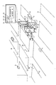
- FIG. 1 shows, by way of example, a schematic representation of an automated handling installation in which handling work is carried out by a robot.
- a robot 2 In an installation comprising circulation aisles such as 1, a robot 2 is required to move to collect objects 3, at locations chosen according to a program, and to come and place them at locations 4 from where they will be later resumed. To this end, the robot includes manipulation arms such as 5 and 6.
- the programs of the instructions to be carried out by the robot are stored in electronic cards called smart cards such as card 7. These cards are stacked, by a handling management operator, in an automatic card dispenser 8.
- the operation of the installation is as follows: when the robot 2 has performed all the tasks that had been programmed for it, in particular by locating on tags such as 9 located at the characteristic locations of the storage area, it approaching the dispenser 8. Approaching the dispenser 8, he actuates a pedal 10 located near this dispenser 8. This pedal 10 causes a motor 11 to be started to insert a new smart card 12 into a smart card reader 13 secured to the robot 2. At the time of this insertion, the robot can reject by a hatch 14 into a recovery tank 15 a previous smart card for which it has just carried out the instructions.
- the dispenser includes to allow insertion, for example, a trigger 16 which drives an insertion rod 17. The rod 17 presses, to insert it, on the end of the smart card which is located at the base of the battery contained in the dispenser 8.
- a robot may encounter difficulties. For example, access by one of the tracks to a place in the storage area can be obstructed, for example, by the presence of another robot which is already handling it. In this case, we can decide to pass the execution of the instruction to be executed after the execution of another instruction which would be possible. For example, this other instruction is possible because it requires the use of a traffic lane which is not obstructed by another robot. This unexecuted instruction can then be kept in memory to be executed at the end of all the instructions that make up the program.
- this approach can have two drawbacks. First, the pre-recorded program may have been designed to optimize the movements of the robot, and therefore the execution of automatic tasks.
- smart cards generally comprise a memory (to contain the instructions of the program) and also a microprocessor.
- This microprocessor can then take account of the execution constraints of the program or programs which are recorded there, these constraints being essentially linked to the actual running of the program, and allow the optimization of the execution of these tasks which had to be omitted because their execution has temporarily been made impossible.
- the microprocessor can allow, by a recorded program, to optimize the sequence of these executions again as a function of the real situation.
- the storage area has connected regions and that the robot program consisted in transporting objects located in an area 17, in a connected area 18 in area 17, objects located in a area 18, in a related area 19 of area 18, and so on. If by example, the transfer in the regions 19 of the objects contained in the regions 18 cannot be temporarily carried out, it may be useful to wait for the robot to replace itself in a region 20 close to the region 18 to perform these tasks which do not have not been performed. This is preferable to the solution which consists in waiting for the robot to finish its round and for it to be at the other end of the warehouse, for example near a region 21. In this case, in fact, the loss of time corresponds to the transit time of this robot from region 21 to region 18.
- the smart cards 7 therefore comprise storage areas 22 for exchanging, by connections such as 23 and contact metallizations 24 appearing on the surface of these cards, the instructions to be executed with the robot 2. They also include a microprocessor 25 responsible for managing the optimization of the execution of the tasks.
- the use of these memory cards can also be improved by increasing the interactive nature of these cards with the robot: the robot can, with recording functions of its reader 13 (which is then a reader-recorder) introduce into the memory zone 22 of the card 7, information relating to the conditions of execution of its task: temperature of the storage area, duration of elementary transport, etc. After the cards have been taken from the recovery bin 15, it is possible to proceed to the examination of the information they contain.
- the cards may contain, on one of their faces (preferably on the one which is intended to be turned upwards in the stack), indications in plain language. These indications, such as, for example "PROGRAM 3 - RANGE N", provide information on the nature of the program stored in the card. These indications can also be replaced by logotypes.
Abstract
Description
La présente invention a pour objet un système de commande d'un robot. Elle concerne plus particulièrement des robots dont la commande est de type électronique. L'emploi de tels robots se généralise, notamment dans le domaine de la manutention d'objets stockés dans des entrepôts. L'invention vise essentiellement à faciliter les tâches de gestion et d'utilisation de tels robots par des personnels à priori non qualifiés.The present invention relates to a robot control system. It relates more particularly to robots whose control is of electronic type. The use of such robots is becoming widespread, especially in the field of handling objects stored in warehouses. The invention essentially aims to facilitate the tasks of management and use of such robots by a priori unqualified personnel.
On connaît, par exemple, des robots de manutention dont la mission consiste à prélever des objets sur un stock, à les transporter, et à les placer en un autre endroit, d'où ils sont destinés à être repris en vue de leur distribution à un destinataire, à un client. Des installations automatisées de commande de ces robots sont de deux type. Dans un premier type, l'entrepôt est aménagé de manière à ce que, sur les lieux de passage du robot, des fils électriques soient enterrés. Ils sont destinés à l'alimentation en puissance de ce robot ainsi qu'à sa commande. L'inconvénient des installations de ce type est qu'elles ne sont pas souples : elles ne peuvent pas être modifiées ou complétées facilement et en plus elles sont chères. En effet elles nécessitent une infrastructure importante dans les entrepôts. Celle-ci est bien plus exigeante que la simple réalisation de surfaces lisses sur le sol de l'entrepôt pour permettre de laisser circuler les robots. Dans un autre type d'installation, plus souple, les robots sont télécommandés par des ondes électromagnétiques. Ce dernier type d'installation, tout en étant moins cher, présente de nombreux inconvénients : essentiellement la propagation des ondes électromagnétiques ne peut pas être assurée dans de bonnes conditions dans tous les milieux industriels. La transmission des instructions d'exécution aux robots n'est pas sûre.We know, for example, handling robots whose mission is to pick up objects from a stock, transport them, and place them in another place, from where they are intended to be picked up for distribution to a recipient, to a client. There are two types of automated control systems for these robots. In a first type, the warehouse is arranged so that, on the places where the robot passes, electrical wires are buried. They are intended for the power supply of this robot as well as for its control. The disadvantage of installations of this type is that they are not flexible: they cannot be modified or supplemented easily and in addition they are expensive. Indeed, they require significant infrastructure in warehouses. This is much more demanding than simply creating smooth surfaces on the warehouse floor to allow the robots to circulate. In another, more flexible type of installation, the robots are remote-controlled by electromagnetic waves. This last type of installation, while being less expensive, has many drawbacks: essentially the propagation of electromagnetic waves cannot be ensured under good conditions in all industrial environments. Transmission of execution instructions to robots is not secure.
Quel que soit le système de transmission des instructions au robot, il apparaît un autre problème. Le problème concerne la qualification des personnels chargés de gérer les robots. Cette qualification est, chez certains d'entre eux, insuffisante. En pratique, ces personnels ne sont pas aptes à dicter, même en un langage informatique très évolué, les instructions à faire exécuter par les robots. Il en résulte que les personnels affectés à de telles tâches doivent être plus qualifiés. Ceci entraîne des coûts salariaux plus importants.Whatever the system for transmitting instructions to the robot, another problem appears. The problem concerns the qualification of the personnel responsible for managing the robots. This qualification is, for some of them, insufficient. In practice, these personnel are not capable of dictating, even in a very advanced computer language, the instructions to be executed by the robots. As a result, the personnel assigned to such tasks must be more qualified. This results in higher salary costs.
Si, en outre, dans une installation automatique, il est prévu de gérer plusieurs robots, la définition d'un système compliqué de gestion de l'ensemble de ces robots doit être mise au point. Cette définition prend beaucoup de temps. Elle impose ipso facto une centralisation de la commande des robots et justifie encore plus la nomination de personnels qualifiés pour gérer des opérations qui, en elles-mêmes, sont peu complexes et qui pourraient normalement être effectuées par des manutentionnaires. Ultérieurement, la modification de ce système complexe est elle-même complexe. En retenant un tel mode centralisé de gestion, on adhère, en définitive, à un système dont l'évolution sera toujours entravée par sa spécificité.If, in addition, in an automatic installation, it is planned to manage several robots, the definition of a complicated system for managing all of these robots must be developed. This definition takes a long time. It ipso facto imposes a centralization of robot control and even more justifies the appointment of qualified personnel to manage operations which, in themselves, are not very complex and which could normally be carried out by handlers. Subsequently, the modification of this complex system is itself complex. By adopting such a centralized mode of management, we ultimately adhere to a system whose evolution will always be hampered by its specificity.
L'invention a pour objet de remédier à ces inconvénients en proposant un système de commande des robots à caractère universel dans lequel les robots viennent se servir auprès d'un distributeur automatique. Ils y prélèvent des cartes électroniques, dites cartes à puce, comportant en mémoire un programme d'instructions à exécuter par ce robot. La tâche des manutentionnaires consiste alors simplement, en fonction des commandes de travaux à exécuter, à empiler dans le distributeur les cartes électroniques à mémoire correspondant à la chronologie de ces commandes. Pour faciliter leur tâche, ces cartes à mémoire, qui sont sensiblement planes, portent sur une de leurs faces un emplacement destiné à recevoir des indications compréhensibles. Ces indications représentent, éventuellement d'une manière symbolique, le programme à exécuter. L'enregistrement des programmes dans les cartes à puce simplifie le travail des ouvriers manutentionnaires. La lecture des programmes d'instructions contenus dans ces cartes, par un lecteur de carte porté par le robot, assure alors d'une manière simple la transmission des instructions à exécuter. Pour son déplacement le robot peut ensuite utiliser la présence de balises de repérage situées sur son parcours.The object of the invention is to remedy these drawbacks by proposing a universal robot control system in which the robots come use at a vending machine. They pick up electronic cards, called smart cards, containing in memory an instruction program to be executed by this robot. The task of the handlers then consists simply, according to the work orders to be executed, to stack in the distributor the electronic memory cards corresponding to the chronology of these orders. To facilitate their task, these memory cards, which are substantially planar, carry on one of their faces a space intended to receive comprehensible indications. These indications represent, possibly in a symbolic way, the program to be executed. Saving programs in smart cards simplifies the work of material handlers. Reading the instruction programs contained in these cards, by a card reader carried by the robot, then ensures in a simple manner the transmission of the instructions to be executed. For its movement the robot can then use the presence of tracking tags located on its path.
L'invention a donc pour objet un système de commande d'un robot comportant des moyens d'enregistrer des programmes d'instructions et des moyens de transmettre ces programmes d'instructions au robot, et, dans le robot, des moyens de recevoir ces instructions et de les exécuter, caractérisé en ce qu'il comporte dans les moyens d'enregistrer ces instructions des cartes dites à puce, ces cartes étant munies d'un microprocesseur.The invention therefore relates to a robot control system comprising means for recording instruction programs and means for transmitting these instruction programs to the robot, and, in the robot, means for receiving these instructions and to execute them, characterized in that it comprises, in the means of recording these instructions, so-called smart cards, these cards being provided with a microprocessor.
L'invention sera mieux comprise à la lecture de la description qui suit et à l'examen de la figure qui l'accompagne. Celles-ci ne sont données qu'à titre indicatif et nullement limitatif de l'invention.The invention will be better understood on reading the description which follows and on examining the accompanying figure. These are given for information only and in no way limit the invention.
La figure 1 unique montre, à titre d'exemple, une représentation schématique d'une installation de manutention automatisée dans laquelle des travaux de manutention sont effectués par un robot.The single FIG. 1 shows, by way of example, a schematic representation of an automated handling installation in which handling work is carried out by a robot.
Dans une installation comportant des allées de circulation telles que 1 un robot 2 est amené à se déplacer pour prélever des objets 3, en des endroits choisis en fonction d'un programme, et pour venir les placer en des lieux 4 d'où ils seront ultérieurement repris. A cette fin, le robot comporte des bras de manipulation tels que 5 et 6. Ce qui caractérise l'invention est que les programmes des instructions à accomplir par le robot sont mémorisés dans des cartes électroniques dites cartes à puce telles que la carte 7. Ces cartes sont empilées, par un opérateur de gestion de la manutention, dans un distributeur 8 automatique de cartes.In an installation comprising circulation aisles such as 1, a robot 2 is required to move to collect
Le fonctionnement de l'installation est le suivant : lorsque le robot 2 a exécuté toutes les tâches qu'on lui avait programmées, notamment en se repérant sur des balises telles que 9 situées aux endroits caractéristiques de l'aire de stockage, il s'approche du distributeur 8. En s'approchant du distributeur 8 il actionne une pédale 10 située à proximité de ce distributeur 8. Cette pédale 10 provoque la mise en marche d'un moteur 11 d'insertion d'une nouvelle carte à puce 12 dans un lecteur 13 de cartes à puce solidaire du robot 2. Au moment de cette insertion, le robot peut rejeter par une trappe 14 dans un bac de récupération 15 une précédente carte à puce dont il vient d'effectuer les instructions. Le distributeur comporte pour permettre l'insertion, par exemple, une gachette 16 qui entraîne une tige d'insertion 17. La tige 17 appuie, pour l'insérer, sur l'extrémité de la carte à puce qui se trouve à la base de la pile contenue dans le distributeur 8.The operation of the installation is as follows: when the robot 2 has performed all the tasks that had been programmed for it, in particular by locating on tags such as 9 located at the characteristic locations of the storage area, it approaching the
L'intérêt de la solution de l'invention se présente en particulier lorsque l'installation est complexe : lorsqu'elle est destinée à travailler avec plusieurs robots. En effet, le prochain robot qui s'approche du distributeur 8 prélève la nouvelle carte qui se trouve à la base de cette pile de sorte que la répartition des tâches entre les différents robots s'effectue sans que le manutentionnaire ait à évaluer la durée d'exécution de chacune et sans qu'il ait à affecter, au risque de se tromper et de perdre du temps, une certaine somme de travail à un robot plutôt qu'à un autre.The advantage of the solution of the invention arises in particular when the installation is complex: when it is intended to work with several robots. Indeed, the next robot which approaches the
En outre, au cours de l'exécution des instructions du programme contenu dans sa carte à puce, un robot peut rencontrer des difficultés. Par exemple l'accès par une des voies à un endroit de l'aire de stockage peut être obstrué, par exemple, par la présence d'un autre robot qui est déjà en train d'y manipuler. On peut dans ce cas décider de faire passer l'exécution de l'instruction à exécuter après l'exécution d'une autre instruction qui, elle, serait possible. Par exemple, cette autre instruction est possible parce qu'elle nécessite l'emprunt d'une voie de circulation qui n'est pas obstruée par un autre robot. Cette instruction non exécutée peut alors être gardée en mémoire pour être exécutée à la fin de toutes les instructions qui composent le programme. Cependant, cette manière de faire peut avoir deux inconvénients. Premièrement le programme pré-enregistré peut avoir été conçu de manière à optimiser les déplacements du robot, et donc l'exécution des tâches automatiques. Le fait de faire sauter certaines tâches et de les replacer, au moment où elles sont omises, à la fin de la liste des instructions à effectuer par le programme, peut amener une perte considérable d'efficacité dans l'exécution de ce programme. En outre, certaines opérations ne doivent pas être effectuées après certaines autres : par exemple il n'est pas conseillé de charger des objets lourds au dessus d'objets fragiles.In addition, during the execution of the instructions of the program contained in its smart card, a robot may encounter difficulties. For example, access by one of the tracks to a place in the storage area can be obstructed, for example, by the presence of another robot which is already handling it. In this case, we can decide to pass the execution of the instruction to be executed after the execution of another instruction which would be possible. For example, this other instruction is possible because it requires the use of a traffic lane which is not obstructed by another robot. This unexecuted instruction can then be kept in memory to be executed at the end of all the instructions that make up the program. However, this approach can have two drawbacks. First, the pre-recorded program may have been designed to optimize the movements of the robot, and therefore the execution of automatic tasks. Skipping certain tasks and replacing them when where they are omitted, at the end of the list of instructions to be carried out by the program, can lead to a considerable loss of efficiency in the execution of this program. In addition, certain operations should not be carried out after certain others: for example it is not advisable to load heavy objects on top of fragile objects.
La solution la plus simple pour remédier à ces inconvénients peut être d'attendre que la voie de circulation obstruée par le robot soit libérée. Dans l'invention, on a découvert qu'il peut être tiré parti du fait que les cartes à puces comportent généralement une mémoire (pour contenir les instructions du programme) et aussi un microprocesseur. Ce microprocesseur peut alors tenir compte des contraintes d'exécution du ou des programmes qui y sont enregistrés, ces contraintes étant essentiellement liées au déroulement effectif du programme, et permettre l'optimisation de l'exécution de ces tâches qui ont dû être omises parce que leur exécution a momentanément été rendue impossible. En résumé, plutôt que de remplacer petit à petit le déroulement organisé des instructions du programme par un déroulement anarchique résultant des contraintes effectives d'exécution, le microprocesseur peut permettre par un programme enregistré, d'optimiser à nouveau le déroulement de ces exécutions en fonction de la situation réelle.The simplest solution to remedy these drawbacks may be to wait until the taxiway obstructed by the robot is released. In the invention, it has been discovered that it can be taken advantage of the fact that smart cards generally comprise a memory (to contain the instructions of the program) and also a microprocessor. This microprocessor can then take account of the execution constraints of the program or programs which are recorded there, these constraints being essentially linked to the actual running of the program, and allow the optimization of the execution of these tasks which had to be omitted because their execution has temporarily been made impossible. In summary, rather than gradually replacing the organized sequence of program instructions with an uncontrolled sequence resulting from the actual execution constraints, the microprocessor can allow, by a recorded program, to optimize the sequence of these executions again as a function of the real situation.
Supposons, par exemple, que l'aire de stockage comporte des régions connexes et que le programme du robot ait consisté à transporter des objets, situés dans une aire 17, dans une aire 18 connexe de l'aire 17, des objets situés dans une aire 18, dans une aire 19 connexe de l'aire 18, et ainsi de suite. Si, par exemple, le transfert dans les régions 19 des objets contenus dans les régions 18 ne peut pas être momentanément effectué, il peut être utile d'attendre que le robot se replace dans une région 20 proche de la région 18 pour effectuer ces tâches qui n'ont pas été effectuées. Ceci est préférable à la solution qui consiste à attendre que le robot ait terminé sa ronde et qu'il se trouve à l,autre bout de l'entrepôt, par exemple à proximité d'une région 21. Dans ce cas, en effet, la perte de temps correspond au temps de transit de ce robot de la région 21 jusqu'à la région 18. On peut, par exemple, concevoir un programme d'optimisation qui impose que les numéros d'ordre des régions à fréquenter ne soient pas trop différents les uns des autres, d'une instruction à l'autre.Suppose, for example, that the storage area has connected regions and that the robot program consisted in transporting objects located in an
Dans ce but, les cartes à puce 7 comportent donc des zones de mémorisation 22 pour échanger, par des connexions telles que 23 et des métallisations de contact 24 apparaissant en surface de ces cartes, les instructions à exécuter avec le robot 2. Elles comportent aussi un microprocesseur 25 chargé de gérer l'optimisation de l'exécution des tâches. L'utilisation de ces cartes à mémoire peut en outre être amélioré en augmentant le caractère interactif de ces cartes avec le robot : le robot peut avec des fonctions d'enregistrement de son lecteur 13 (qui est alors un lecteur-enregistreur) introduire dans la zone mémoire 22 de la carte 7, des informations relatives aux conditions d'exécution de sa tâche : température de l'aire de stockage, durée des transports élémentaires etc... Après le prélèvement des cartes dans le bac de récupération 15, on peut procéder au dépouillement des informations qu'elles contiennent.For this purpose, the
Pour faciliter la tâche des opérateurs, les cartes peuvent contenir, sur une de leur face (de préférence sur celle qui est destinée à être tournée vers le dessus dans la pile), des indications en langage clair. Ces indications, telles que, par exemple "PROGRAMME 3 - RANGEE N", renseignent sur la nature du programme enregistré dans la carte. Ces indications peuvent aussi être remplacées par des logotypes.To make it easier for operators, the cards may contain, on one of their faces (preferably on the one which is intended to be turned upwards in the stack), indications in plain language. These indications, such as, for example "PROGRAM 3 - RANGE N", provide information on the nature of the program stored in the card. These indications can also be replaced by logotypes.
Claims (8)
Applications Claiming Priority (2)
| Application Number | Priority Date | Filing Date | Title |
|---|---|---|---|
| FR8717388A FR2624633B1 (en) | 1987-12-14 | 1987-12-14 | ROBOT PROGRAMMING SYSTEM |
| FR8717388 | 1987-12-14 |
Publications (2)
| Publication Number | Publication Date |
|---|---|
| EP0321325A1 true EP0321325A1 (en) | 1989-06-21 |
| EP0321325B1 EP0321325B1 (en) | 1992-09-16 |
Family
ID=9357825
Family Applications (1)
| Application Number | Title | Priority Date | Filing Date |
|---|---|---|---|
| EP88403138A Expired - Lifetime EP0321325B1 (en) | 1987-12-14 | 1988-12-09 | Control system of a robot |
Country Status (7)
| Country | Link |
|---|---|
| US (1) | US5031109A (en) |
| EP (1) | EP0321325B1 (en) |
| JP (1) | JPH01303510A (en) |
| KR (1) | KR890009551A (en) |
| DE (1) | DE3874704T2 (en) |
| ES (1) | ES2034341T3 (en) |
| FR (1) | FR2624633B1 (en) |
Cited By (5)
| Publication number | Priority date | Publication date | Assignee | Title |
|---|---|---|---|---|
| EP0504866A2 (en) * | 1991-03-22 | 1992-09-23 | Allen-Bradley Company, Inc. | Programmable controller processor with a removable function card |
| FR2698976A1 (en) * | 1992-12-09 | 1994-06-10 | Delta Dore | Programmable controller for heating installation - uses smart card that is programmed by specialist and forwarded to user, who has reader to allow use of stored program |
| EP0857684A1 (en) * | 1997-02-10 | 1998-08-12 | Inventio Ag | Method and device for installation and maintenance of controllers for elevator systems |
| US5969305A (en) * | 1997-02-10 | 1999-10-19 | Inventio Ag | Method and apparatus for installing and maintaining elevator system controls |
| US9176750B2 (en) | 2008-10-30 | 2015-11-03 | Oberthur Technologies | Telephone network subscriber identification card and method of controlling an electronic device adapted to interact with such a card |
Families Citing this family (23)
| Publication number | Priority date | Publication date | Assignee | Title |
|---|---|---|---|---|
| EP0466004B2 (en) * | 1990-07-10 | 1997-11-19 | Daifuku Co., Ltd. | Control system for automatic warehousing facility |
| JPH05181527A (en) * | 1991-12-27 | 1993-07-23 | Mitsubishi Electric Corp | Automatic conveyer |
| US5550953A (en) * | 1994-04-20 | 1996-08-27 | The United States Of America As Represented By The Administrator Of The National Aeronautics And Space Administration | On-line method and apparatus for coordinated mobility and manipulation of mobile robots |
| DE4408982C1 (en) * | 1994-03-16 | 1995-05-18 | Deutsche Forsch Luft Raumfahrt | Autonomous navigation system for mobile robot or manipulator |
| FR2724477B1 (en) * | 1994-09-13 | 1997-01-10 | Gemplus Card Int | NON-CONTACT CARD MANUFACTURING PROCESS |
| US5453931A (en) * | 1994-10-25 | 1995-09-26 | Watts, Jr.; James R. | Navigating robot with reference line plotter |
| US5724074A (en) * | 1995-02-06 | 1998-03-03 | Microsoft Corporation | Method and system for graphically programming mobile toys |
| US8512219B2 (en) | 2004-04-19 | 2013-08-20 | The Invention Science Fund I, Llc | Bioelectromagnetic interface system |
| US8337482B2 (en) | 2004-04-19 | 2012-12-25 | The Invention Science Fund I, Llc | System for perfusion management |
| US8092549B2 (en) | 2004-09-24 | 2012-01-10 | The Invention Science Fund I, Llc | Ciliated stent-like-system |
| US8353896B2 (en) | 2004-04-19 | 2013-01-15 | The Invention Science Fund I, Llc | Controllable release nasal system |
| US8361013B2 (en) | 2004-04-19 | 2013-01-29 | The Invention Science Fund I, Llc | Telescoping perfusion management system |
| US9011329B2 (en) | 2004-04-19 | 2015-04-21 | Searete Llc | Lumenally-active device |
| US8024036B2 (en) | 2007-03-19 | 2011-09-20 | The Invention Science Fund I, Llc | Lumen-traveling biological interface device and method of use |
| US8936629B2 (en) * | 2006-04-12 | 2015-01-20 | Invention Science Fund I Llc | Autofluorescent imaging and target ablation |
| US20120035438A1 (en) | 2006-04-12 | 2012-02-09 | Searete Llc, A Limited Liability Corporation Of The State Of Delaware | Path selection by a lumen traveling device in a body tub tree based on previous path |
| US8163003B2 (en) * | 2006-06-16 | 2012-04-24 | The Invention Science Fund I, Llc | Active blood vessel sleeve methods and systems |
| US20110199194A1 (en) * | 2008-08-11 | 2011-08-18 | Nxp B.V. | Programmable device and programming method |
| FR2938097B1 (en) * | 2008-10-30 | 2010-12-31 | Oberthur Technologies | MICROCIRCUIT CARD, ELECTRONIC DEVICE ASSOCIATED WITH SUCH CARD, AND METHOD FOR CONTROLLING SUCH AN ELECTRONIC DEVICE |
| FR2942060B1 (en) * | 2009-02-11 | 2016-02-12 | Oberthur Technologies | ELECTRONIC ENTITY CAPABLE OF COMMUNICATING WITH A READER AND METHOD IMPLEMENTED WITHIN SUCH AN ELECTRONIC ENTITY |
| CN103935771B (en) * | 2014-05-08 | 2016-04-13 | 安徽埃夫特智能装备有限公司 | A kind of electric-control system of piling industrial robot |
| US9776324B1 (en) | 2016-03-25 | 2017-10-03 | Locus Robotics Corporation | Robot queueing in order-fulfillment operations |
| US10913604B2 (en) | 2017-06-21 | 2021-02-09 | Locus Robotics Corp. | System and method for queuing robots destined for one or more processing stations |
Citations (6)
| Publication number | Priority date | Publication date | Assignee | Title |
|---|---|---|---|---|
| FR2385178A1 (en) * | 1977-03-21 | 1978-10-20 | Courtois Andre | Interchangeable programming cassette for automatic sewing machine - has PROM or RE-PROM MOSFET memories in flat plug-in housing |
| FR2477303A1 (en) * | 1980-02-28 | 1981-09-04 | Dassault Electronique | Printed circuit electronic identification card reader - uses external activation to open shutter to allow card to be drawn in to stop before shutter is closed during processing |
| EP0147337A2 (en) * | 1983-12-30 | 1985-07-03 | Bull S.A. | Method and system for confidentially processing information registered on a portable carrier recording track with optical reading |
| EP0167211A1 (en) * | 1984-07-03 | 1986-01-08 | Laboratoires D'electronique Et De Physique Appliquee L.E.P. | Washing-machine provided with a numerical interface adapter circuit assuring the communication with a card reader with an electronic memory, and washing-machine with an electronic card |
| WO1986006303A1 (en) * | 1985-05-02 | 1986-11-06 | Robert Bosch Gmbh | Control system for mobile transport units on transport tracks |
| EP0227113A2 (en) * | 1985-12-23 | 1987-07-01 | Kitamura Machinery Co.,Ltd. | CNC machine tool |
Family Cites Families (3)
| Publication number | Priority date | Publication date | Assignee | Title |
|---|---|---|---|---|
| US4467436A (en) * | 1981-10-26 | 1984-08-21 | United States Robots, Inc. | Robot arm controller with common bus memory |
| US4674048A (en) * | 1983-10-26 | 1987-06-16 | Automax Kabushiki-Kaisha | Multiple robot control system using grid coordinate system for tracking and completing travel over a mapped region containing obstructions |
| JPS63289607A (en) * | 1987-05-21 | 1988-11-28 | Toshiba Corp | Inter-module communication control system for intelligent robot |
-
1987
- 1987-12-14 FR FR8717388A patent/FR2624633B1/en not_active Expired - Lifetime
-
1988
- 1988-12-09 EP EP88403138A patent/EP0321325B1/en not_active Expired - Lifetime
- 1988-12-09 DE DE8888403138T patent/DE3874704T2/en not_active Expired - Fee Related
- 1988-12-09 ES ES198888403138T patent/ES2034341T3/en not_active Expired - Lifetime
- 1988-12-10 KR KR1019880016487A patent/KR890009551A/en not_active Application Discontinuation
- 1988-12-14 JP JP63316072A patent/JPH01303510A/en active Pending
-
1990
- 1990-08-20 US US07/569,960 patent/US5031109A/en not_active Expired - Fee Related
Patent Citations (6)
| Publication number | Priority date | Publication date | Assignee | Title |
|---|---|---|---|---|
| FR2385178A1 (en) * | 1977-03-21 | 1978-10-20 | Courtois Andre | Interchangeable programming cassette for automatic sewing machine - has PROM or RE-PROM MOSFET memories in flat plug-in housing |
| FR2477303A1 (en) * | 1980-02-28 | 1981-09-04 | Dassault Electronique | Printed circuit electronic identification card reader - uses external activation to open shutter to allow card to be drawn in to stop before shutter is closed during processing |
| EP0147337A2 (en) * | 1983-12-30 | 1985-07-03 | Bull S.A. | Method and system for confidentially processing information registered on a portable carrier recording track with optical reading |
| EP0167211A1 (en) * | 1984-07-03 | 1986-01-08 | Laboratoires D'electronique Et De Physique Appliquee L.E.P. | Washing-machine provided with a numerical interface adapter circuit assuring the communication with a card reader with an electronic memory, and washing-machine with an electronic card |
| WO1986006303A1 (en) * | 1985-05-02 | 1986-11-06 | Robert Bosch Gmbh | Control system for mobile transport units on transport tracks |
| EP0227113A2 (en) * | 1985-12-23 | 1987-07-01 | Kitamura Machinery Co.,Ltd. | CNC machine tool |
Non-Patent Citations (2)
| Title |
|---|
| LE NOUVEL AUTOMATISME vol. 29, no. 45, avril 1984, Paris France page 65 - 73; M. FERRETTI: "Automoteurs et Transtockeurs, la manutention automatisee" * |
| PATENT ABSTRACTS OF JAPAN vol. 11, no. 256 (P-607) 2703 20 août 1987, & JP-A-62 63305 (MITSUBISHI ELECTRIC CORP.) * |
Cited By (7)
| Publication number | Priority date | Publication date | Assignee | Title |
|---|---|---|---|---|
| EP0504866A2 (en) * | 1991-03-22 | 1992-09-23 | Allen-Bradley Company, Inc. | Programmable controller processor with a removable function card |
| EP0504866A3 (en) * | 1991-03-22 | 1993-10-20 | Allen Bradley Co | Programmable controller processor with a removable function card |
| US5410717A (en) * | 1991-03-22 | 1995-04-25 | Allen-Bradley Company, Inc. | Removable function card for a programmable controller processor |
| FR2698976A1 (en) * | 1992-12-09 | 1994-06-10 | Delta Dore | Programmable controller for heating installation - uses smart card that is programmed by specialist and forwarded to user, who has reader to allow use of stored program |
| EP0857684A1 (en) * | 1997-02-10 | 1998-08-12 | Inventio Ag | Method and device for installation and maintenance of controllers for elevator systems |
| US5969305A (en) * | 1997-02-10 | 1999-10-19 | Inventio Ag | Method and apparatus for installing and maintaining elevator system controls |
| US9176750B2 (en) | 2008-10-30 | 2015-11-03 | Oberthur Technologies | Telephone network subscriber identification card and method of controlling an electronic device adapted to interact with such a card |
Also Published As
| Publication number | Publication date |
|---|---|
| US5031109A (en) | 1991-07-09 |
| KR890009551A (en) | 1989-08-02 |
| FR2624633A1 (en) | 1989-06-16 |
| DE3874704T2 (en) | 1993-02-11 |
| JPH01303510A (en) | 1989-12-07 |
| ES2034341T3 (en) | 1993-04-01 |
| EP0321325B1 (en) | 1992-09-16 |
| DE3874704D1 (en) | 1992-10-22 |
| FR2624633B1 (en) | 1992-09-11 |
Similar Documents
| Publication | Publication Date | Title |
|---|---|---|
| EP0321325B1 (en) | Control system of a robot | |
| US9409711B1 (en) | Semi-automated inventory transfer station output merge logic | |
| US9555978B1 (en) | Semi-automated inventory transfer station | |
| US4312623A (en) | High through-put materials handling system and method | |
| KR100346666B1 (en) | Retrieval of serpentine pattern data using a memory device of a tape cartridge | |
| CN1229505A (en) | Storage medium having electronic circuit and computer system having the storage medium | |
| EP0897160B1 (en) | Installation and method for processing batches of orders by distributing products in a storage area and device for applying the method | |
| EP3943419B1 (en) | Dynamic storage apparatus and dynamic storage and taking management method | |
| CN102132344A (en) | Automated data storage library with multi-cartridge deep slot cells | |
| WO2019128180A1 (en) | Inventory replenishment method and device for unmanned smart retail terminal | |
| JP2019137496A (en) | Storage system | |
| JPH06260545A (en) | Production control system of semiconductor wafer | |
| CN104350496A (en) | Method and apparatus for mass updates of digital media | |
| TW202006381A (en) | Apparatus for relocating electronic components | |
| CN112486110B (en) | Silicon wafer production system | |
| EP2507749B1 (en) | Machine for the electrical and graphic customisation of portable electronic objects | |
| CN114358672A (en) | Roadway arrangement method and device, electronic equipment and computer readable medium | |
| FR2634571A1 (en) | METHOD OF ORGANIZING AND READING A MAGNETIC MEDIUM AND SUPPORT BY APPLYING | |
| JPH05147723A (en) | Physical distribution management system | |
| FR3016718A1 (en) | SYSTEM FOR MANAGING AN ENTREPROT FOR THE PREPARATION OF CONTROLS AND METHOD FOR IMPLEMENTING IT | |
| JP2003108213A (en) | Self-control management system | |
| CN213814750U (en) | Manufacturing system of smart card | |
| EP0549696B1 (en) | Method and device for controlling and monitoring processes using information furnished by electronically-labelled articles | |
| JP7091409B2 (en) | Luggage transport system | |
| JPH08285855A (en) | Specimen sorting system |
Legal Events
| Date | Code | Title | Description |
|---|---|---|---|
| PUAI | Public reference made under article 153(3) epc to a published international application that has entered the european phase |
Free format text: ORIGINAL CODE: 0009012 |
|
| AK | Designated contracting states |
Kind code of ref document: A1 Designated state(s): DE ES GB IT NL |
|
| 17P | Request for examination filed |
Effective date: 19890717 |
|
| 17Q | First examination report despatched |
Effective date: 19910322 |
|
| GRAA | (expected) grant |
Free format text: ORIGINAL CODE: 0009210 |
|
| ITF | It: translation for a ep patent filed |
Owner name: ING. C. SPANDONARI |
|
| AK | Designated contracting states |
Kind code of ref document: B1 Designated state(s): DE ES GB IT NL |
|
| REF | Corresponds to: |
Ref document number: 3874704 Country of ref document: DE Date of ref document: 19921022 |
|
| GBT | Gb: translation of ep patent filed (gb section 77(6)(a)/1977) | ||
| REG | Reference to a national code |
Ref country code: ES Ref legal event code: FG2A Ref document number: 2034341 Country of ref document: ES Kind code of ref document: T3 |
|
| PLBE | No opposition filed within time limit |
Free format text: ORIGINAL CODE: 0009261 |
|
| STAA | Information on the status of an ep patent application or granted ep patent |
Free format text: STATUS: NO OPPOSITION FILED WITHIN TIME LIMIT |
|
| 26N | No opposition filed | ||
| PGFP | Annual fee paid to national office [announced via postgrant information from national office to epo] |
Ref country code: DE Payment date: 19931202 Year of fee payment: 6 |
|
| PGFP | Annual fee paid to national office [announced via postgrant information from national office to epo] |
Ref country code: GB Payment date: 19931203 Year of fee payment: 6 |
|
| PGFP | Annual fee paid to national office [announced via postgrant information from national office to epo] |
Ref country code: ES Payment date: 19931217 Year of fee payment: 6 |
|
| PGFP | Annual fee paid to national office [announced via postgrant information from national office to epo] |
Ref country code: NL Payment date: 19931231 Year of fee payment: 6 |
|
| PG25 | Lapsed in a contracting state [announced via postgrant information from national office to epo] |
Ref country code: GB Effective date: 19941209 |
|
| PG25 | Lapsed in a contracting state [announced via postgrant information from national office to epo] |
Ref country code: ES Free format text: LAPSE BECAUSE OF THE APPLICANT RENOUNCES Effective date: 19941210 |
|
| PG25 | Lapsed in a contracting state [announced via postgrant information from national office to epo] |
Ref country code: NL Effective date: 19950701 |
|
| GBPC | Gb: european patent ceased through non-payment of renewal fee |
Effective date: 19941209 |
|
| NLV4 | Nl: lapsed or anulled due to non-payment of the annual fee |
Effective date: 19950701 |
|
| PG25 | Lapsed in a contracting state [announced via postgrant information from national office to epo] |
Ref country code: DE Effective date: 19950901 |
|
| REG | Reference to a national code |
Ref country code: ES Ref legal event code: FD2A Effective date: 20010402 |
|
| PG25 | Lapsed in a contracting state [announced via postgrant information from national office to epo] |
Ref country code: IT Free format text: LAPSE BECAUSE OF NON-PAYMENT OF DUE FEES;WARNING: LAPSES OF ITALIAN PATENTS WITH EFFECTIVE DATE BEFORE 2007 MAY HAVE OCCURRED AT ANY TIME BEFORE 2007. THE CORRECT EFFECTIVE DATE MAY BE DIFFERENT FROM THE ONE RECORDED. Effective date: 20051209 |