EP0321822A2 - Deckenstativ zur Aufnahme von medizinischen Geräten - Google Patents
Deckenstativ zur Aufnahme von medizinischen Geräten Download PDFInfo
- Publication number
- EP0321822A2 EP0321822A2 EP88120738A EP88120738A EP0321822A2 EP 0321822 A2 EP0321822 A2 EP 0321822A2 EP 88120738 A EP88120738 A EP 88120738A EP 88120738 A EP88120738 A EP 88120738A EP 0321822 A2 EP0321822 A2 EP 0321822A2
- Authority
- EP
- European Patent Office
- Prior art keywords
- stand according
- rails
- ceiling
- receiving device
- column
- Prior art date
- Legal status (The legal status is an assumption and is not a legal conclusion. Google has not performed a legal analysis and makes no representation as to the accuracy of the status listed.)
- Granted
Links
- 230000003444 anaesthetic effect Effects 0.000 description 16
- 206010002091 Anaesthesia Diseases 0.000 description 2
- 230000037005 anaesthesia Effects 0.000 description 2
- 238000012806 monitoring device Methods 0.000 description 1
- 239000007787 solid Substances 0.000 description 1
Images
Classifications
-
- F—MECHANICAL ENGINEERING; LIGHTING; HEATING; WEAPONS; BLASTING
- F16—ENGINEERING ELEMENTS AND UNITS; GENERAL MEASURES FOR PRODUCING AND MAINTAINING EFFECTIVE FUNCTIONING OF MACHINES OR INSTALLATIONS; THERMAL INSULATION IN GENERAL
- F16M—FRAMES, CASINGS OR BEDS OF ENGINES, MACHINES OR APPARATUS, NOT SPECIFIC TO ENGINES, MACHINES OR APPARATUS PROVIDED FOR ELSEWHERE; STANDS; SUPPORTS
- F16M11/00—Stands or trestles as supports for apparatus or articles placed thereon Stands for scientific apparatus such as gravitational force meters
- F16M11/02—Heads
- F16M11/04—Means for attachment of apparatus; Means allowing adjustment of the apparatus relatively to the stand
- F16M11/043—Allowing translations
- F16M11/046—Allowing translations adapted to upward-downward translation movement
-
- A—HUMAN NECESSITIES
- A61—MEDICAL OR VETERINARY SCIENCE; HYGIENE
- A61G—TRANSPORT, PERSONAL CONVEYANCES, OR ACCOMMODATION SPECIALLY ADAPTED FOR PATIENTS OR DISABLED PERSONS; OPERATING TABLES OR CHAIRS; CHAIRS FOR DENTISTRY; FUNERAL DEVICES
- A61G12/00—Accommodation for nursing, e.g. in hospitals, not covered by groups A61G1/00 - A61G11/00, e.g. trolleys for transport of medicaments or food; Prescription lists
- A61G12/002—Supply appliances, e.g. columns for gas, fluid, electricity supply
- A61G12/004—Supply appliances, e.g. columns for gas, fluid, electricity supply mounted on the ceiling
-
- A—HUMAN NECESSITIES
- A61—MEDICAL OR VETERINARY SCIENCE; HYGIENE
- A61G—TRANSPORT, PERSONAL CONVEYANCES, OR ACCOMMODATION SPECIALLY ADAPTED FOR PATIENTS OR DISABLED PERSONS; OPERATING TABLES OR CHAIRS; CHAIRS FOR DENTISTRY; FUNERAL DEVICES
- A61G12/00—Accommodation for nursing, e.g. in hospitals, not covered by groups A61G1/00 - A61G11/00, e.g. trolleys for transport of medicaments or food; Prescription lists
- A61G12/002—Supply appliances, e.g. columns for gas, fluid, electricity supply
- A61G12/008—Supply appliances, e.g. columns for gas, fluid, electricity supply mounted on a mobile base, e.g. on a trolley
-
- F—MECHANICAL ENGINEERING; LIGHTING; HEATING; WEAPONS; BLASTING
- F16—ENGINEERING ELEMENTS AND UNITS; GENERAL MEASURES FOR PRODUCING AND MAINTAINING EFFECTIVE FUNCTIONING OF MACHINES OR INSTALLATIONS; THERMAL INSULATION IN GENERAL
- F16M—FRAMES, CASINGS OR BEDS OF ENGINES, MACHINES OR APPARATUS, NOT SPECIFIC TO ENGINES, MACHINES OR APPARATUS PROVIDED FOR ELSEWHERE; STANDS; SUPPORTS
- F16M11/00—Stands or trestles as supports for apparatus or articles placed thereon Stands for scientific apparatus such as gravitational force meters
- F16M11/02—Heads
- F16M11/04—Means for attachment of apparatus; Means allowing adjustment of the apparatus relatively to the stand
- F16M11/06—Means for attachment of apparatus; Means allowing adjustment of the apparatus relatively to the stand allowing pivoting
- F16M11/10—Means for attachment of apparatus; Means allowing adjustment of the apparatus relatively to the stand allowing pivoting around a horizontal axis
-
- F—MECHANICAL ENGINEERING; LIGHTING; HEATING; WEAPONS; BLASTING
- F16—ENGINEERING ELEMENTS AND UNITS; GENERAL MEASURES FOR PRODUCING AND MAINTAINING EFFECTIVE FUNCTIONING OF MACHINES OR INSTALLATIONS; THERMAL INSULATION IN GENERAL
- F16M—FRAMES, CASINGS OR BEDS OF ENGINES, MACHINES OR APPARATUS, NOT SPECIFIC TO ENGINES, MACHINES OR APPARATUS PROVIDED FOR ELSEWHERE; STANDS; SUPPORTS
- F16M11/00—Stands or trestles as supports for apparatus or articles placed thereon Stands for scientific apparatus such as gravitational force meters
- F16M11/02—Heads
- F16M11/18—Heads with mechanism for moving the apparatus relatively to the stand
-
- F—MECHANICAL ENGINEERING; LIGHTING; HEATING; WEAPONS; BLASTING
- F16—ENGINEERING ELEMENTS AND UNITS; GENERAL MEASURES FOR PRODUCING AND MAINTAINING EFFECTIVE FUNCTIONING OF MACHINES OR INSTALLATIONS; THERMAL INSULATION IN GENERAL
- F16M—FRAMES, CASINGS OR BEDS OF ENGINES, MACHINES OR APPARATUS, NOT SPECIFIC TO ENGINES, MACHINES OR APPARATUS PROVIDED FOR ELSEWHERE; STANDS; SUPPORTS
- F16M11/00—Stands or trestles as supports for apparatus or articles placed thereon Stands for scientific apparatus such as gravitational force meters
- F16M11/20—Undercarriages with or without wheels
- F16M11/2007—Undercarriages with or without wheels comprising means allowing pivoting adjustment
- F16M11/2021—Undercarriages with or without wheels comprising means allowing pivoting adjustment around a horizontal axis
-
- F—MECHANICAL ENGINEERING; LIGHTING; HEATING; WEAPONS; BLASTING
- F16—ENGINEERING ELEMENTS AND UNITS; GENERAL MEASURES FOR PRODUCING AND MAINTAINING EFFECTIVE FUNCTIONING OF MACHINES OR INSTALLATIONS; THERMAL INSULATION IN GENERAL
- F16M—FRAMES, CASINGS OR BEDS OF ENGINES, MACHINES OR APPARATUS, NOT SPECIFIC TO ENGINES, MACHINES OR APPARATUS PROVIDED FOR ELSEWHERE; STANDS; SUPPORTS
- F16M11/00—Stands or trestles as supports for apparatus or articles placed thereon Stands for scientific apparatus such as gravitational force meters
- F16M11/20—Undercarriages with or without wheels
- F16M11/24—Undercarriages with or without wheels changeable in height or length of legs, also for transport only, e.g. by means of tubes screwed into each other
-
- F—MECHANICAL ENGINEERING; LIGHTING; HEATING; WEAPONS; BLASTING
- F16—ENGINEERING ELEMENTS AND UNITS; GENERAL MEASURES FOR PRODUCING AND MAINTAINING EFFECTIVE FUNCTIONING OF MACHINES OR INSTALLATIONS; THERMAL INSULATION IN GENERAL
- F16M—FRAMES, CASINGS OR BEDS OF ENGINES, MACHINES OR APPARATUS, NOT SPECIFIC TO ENGINES, MACHINES OR APPARATUS PROVIDED FOR ELSEWHERE; STANDS; SUPPORTS
- F16M11/00—Stands or trestles as supports for apparatus or articles placed thereon Stands for scientific apparatus such as gravitational force meters
- F16M11/42—Stands or trestles as supports for apparatus or articles placed thereon Stands for scientific apparatus such as gravitational force meters with arrangement for propelling the support stands on wheels
-
- F—MECHANICAL ENGINEERING; LIGHTING; HEATING; WEAPONS; BLASTING
- F16—ENGINEERING ELEMENTS AND UNITS; GENERAL MEASURES FOR PRODUCING AND MAINTAINING EFFECTIVE FUNCTIONING OF MACHINES OR INSTALLATIONS; THERMAL INSULATION IN GENERAL
- F16M—FRAMES, CASINGS OR BEDS OF ENGINES, MACHINES OR APPARATUS, NOT SPECIFIC TO ENGINES, MACHINES OR APPARATUS PROVIDED FOR ELSEWHERE; STANDS; SUPPORTS
- F16M13/00—Other supports for positioning apparatus or articles; Means for steadying hand-held apparatus or articles
- F16M13/02—Other supports for positioning apparatus or articles; Means for steadying hand-held apparatus or articles for supporting on, or attaching to, an object, e.g. tree, gate, window-frame, cycle
- F16M13/027—Ceiling supports
-
- A—HUMAN NECESSITIES
- A61—MEDICAL OR VETERINARY SCIENCE; HYGIENE
- A61G—TRANSPORT, PERSONAL CONVEYANCES, OR ACCOMMODATION SPECIALLY ADAPTED FOR PATIENTS OR DISABLED PERSONS; OPERATING TABLES OR CHAIRS; CHAIRS FOR DENTISTRY; FUNERAL DEVICES
- A61G13/00—Operating tables; Auxiliary appliances therefor
- A61G13/10—Parts, details or accessories
- A61G13/107—Supply appliances
-
- A—HUMAN NECESSITIES
- A61—MEDICAL OR VETERINARY SCIENCE; HYGIENE
- A61G—TRANSPORT, PERSONAL CONVEYANCES, OR ACCOMMODATION SPECIALLY ADAPTED FOR PATIENTS OR DISABLED PERSONS; OPERATING TABLES OR CHAIRS; CHAIRS FOR DENTISTRY; FUNERAL DEVICES
- A61G2203/00—General characteristics of devices
- A61G2203/70—General characteristics of devices with special adaptations, e.g. for safety or comfort
- A61G2203/80—General characteristics of devices with special adaptations, e.g. for safety or comfort for connecting a trolley to a device, e.g. bed or column table
-
- A—HUMAN NECESSITIES
- A61—MEDICAL OR VETERINARY SCIENCE; HYGIENE
- A61G—TRANSPORT, PERSONAL CONVEYANCES, OR ACCOMMODATION SPECIALLY ADAPTED FOR PATIENTS OR DISABLED PERSONS; OPERATING TABLES OR CHAIRS; CHAIRS FOR DENTISTRY; FUNERAL DEVICES
- A61G2210/00—Devices for specific treatment or diagnosis
- A61G2210/30—Devices for specific treatment or diagnosis for intensive care
Definitions
- the invention relates to a ceiling stand for receiving medical devices with an extension arm and a column and through these supply lines and with a first device receiving device.
- Tripods of this type are used in particular in operating rooms of hospitals.
- a central column carries devices such as a monitor or keyboards that are set to a specific working height and, in the case of monitors, to a specific angle of inclination for the operator. If necessary, further swivel arms can be provided which are firmly connected to the central column. If necessary, these monitors can also be used, which are adjusted according to the working position in their rotational position and in their inclination relative to the horizontal. It is desirable that an anesthesia machine can also be carried on the column, which, however, should also be removable from the column and movable to other places of use. Since such anesthetic devices are too heavy to carry, a known ceiling stand has a kind of fork at the lower end of the boom column.
- anesthetic machine In the bottom of the anesthetic machine to be accommodated there are recesses corresponding to the fork.
- the anesthetic machine is placed on the fork and held by the tripod.
- the anesthesia machine is placed or removed by means of a lifting truck which is adjustable in height so that it receives the anesthetic machine and lifts it off the fork, so that the anesthetic machine can then be removed from the fork by the lifting truck.
- a disadvantage is that only specially adapted anesthetic devices can be accommodated, especially without a fixed chassis.
- the object of the invention is to provide a ceiling mount of the type described in the introduction with which a wide variety of medical devices and in particular anesthetic devices and patient monitoring devices and in particular also those with a chassis can be accommodated.
- the device to be transported under certain circumstances should be raised during its inclusion on the ceiling stand so that there is legroom on the floor.
- the ceiling stand is characterized in that the device receiving device is designed such that it is adjustable in height in such a way that the device receiving device receives a medical device carried by an undercarriage by gripping the undercarriage of the undercarriage.
- the ceiling stand 1 has a bracket 3 to be attached to a ceiling 2 via a joint and a column 4 which is connected to it in an articulated manner.
- the column 4 has a first section 5 and a second section 6 connected to the boom 3.
- a device receiving device 7 is provided, which has a yoke extending transversely to the second section extending in the vertical direction at the bottom end.
- a pair of rails 9, 10 extending horizontally in the working position is arranged on the yoke.
- the connection between the yoke and the rails takes place via a respective swivel joint 11 such that the rails can be folded upwards in the rest position in the manner shown in FIG. 3.
- the second section 6 has a toothed rack 12 and a spindle 13 carrying the yoke.
- the device receiving device can be moved up and down by actuating the spindle in the direction of arrow 14 between the working position shown in solid lines in FIG. 2 and the lowered position shown in broken lines.
- the height is preferably adjusted using a hand crank, which has the advantage that no contact strips or similar safety devices are required.
- the height adjustment can alternatively also be carried out via a motor drive.
- the rails 9, 10 can be extended or retracted in opposite directions to one another in the horizontal direction via a guide shown only schematically in FIG. 1 on the yoke 8 in such a way that the distance between the two rails is narrower than that shown in solid lines in FIG. 1 Position up to a dashed indicated further apart position can be moved back and forth, as indicated by the arrows in Fig. 1. It is thereby achieved that a wide adjustment of the rail to various wheelbases of transport vehicles is possible.
- the rails Both on the side facing the yoke and on the side of the free end, the rails have a plurality of bores 15, 16 which are spaced apart from one another in the direction of the rail and which serve to receive pins which extend across the respective rail and which block the movement of a car 17 placed on the rails with the device 18 carried by it.
- a first monitor support 10 is provided, which is used to hold a first monitor 20.
- the monitor support can be adjusted in height in the direction of arrow 22 via a corresponding spindle 21 on the rack 12, regardless of the height of the device receiving device 7.
- Both the device receiving device 7 and the first monitor carrier can also be pivoted about the column axis in the manner indicated by the arrows shown in FIG. 2.
- the stand carries a second monitor support 23, which is fixedly connected to the first section 5 of the column with respect to the axial direction of the column.
- the first monitor support 19 can alternatively also be connected to the first section 5 of the column.
- the two monitors 20 and 24 are adjusted with respect to their inclination of the screen to the work place in their inclination.
- the anesthetic machine 18 with its carriage 17 is on the rails 9, 10 with the help of the locking pins held stationary and moved so far up above the spindle 13 that there is ground clearance so that the anesthetic machine can also be pivoted about the axis of the second section.
- the anesthetic machine is connected to the supply lines which are led through the stationary first section of the column and are not shown here.
- the device receiving device is lowered to the floor in the position shown in dashed lines in FIG. 2. Then the device is moved away with the car. If desired, the same or a different device can be moved back onto the rails at any time. If the carriage of another device has a different wheelbase, the rails are moved laterally to adapt to it. After picking up the car, it is raised again to the solid position shown. If no carriage is picked up, the rails are folded up into the position shown in FIG. 3. It is not necessary to change the height of the other devices either to hand in a device or to take up a new device. This is essential because it avoids having to re-adjust the inclination of the monitors that have been set for the workplace.
Abstract
Description
- Die Erfindung betrifft ein Deckenstativ zur Aufnahme von medizinischen Geräten mit einem Ausleger und einer Säule und durch diese geführten Versorgungsleitungen und mit einer ersten Geräteaufnahmeeinrichtung.
- Derartige Stative werden insbesondere in Operationsräumen von Krankenhäusern eingesetzt. Eine zentrale Säule trägt Geräte wie einen Monitor oder Tastaturen, die auf eine ganz bestimmte Arbeitshöhe und bei Monitoren auf einen bestimmten Neigungswinkel für die Bedienungsperson eingestellt werden. Gegebenenfalls können weitere Schwenkarme vorgesehen sein, die mit der zentralen Säule fest verbunden sind. Gegebenenfalls können auch diese Monitore tragen, die der Arbeitsposition entsprechend in ihrer Drehstellung und in ihrer Neigung relativ zur Horizontalen eingestellt werden. Es ist erwünscht, daß an der Säule auch ein Narkosegerät getragen werden kann, welches allerdings auch von der Säule abnehmbar und zu anderen Einsatzorten bewegbar sein soll. Da solche Narkosegeräte zum Tragen zu schwer sind, weist ein bekanntes Deckenstativ am unteren Ende der Ausleger-Säule eine Art Gabel auf. Im Boden des aufzunehmenden Narkosegerätes sind der Gabel entsprechende Ausnehmungen vorhanden. Das Narkosegerät wird auf die Gabel aufgesetzt und so von dem Stativ gehalten. Das Aufsetzen bzw. Abnehmen des Narkosegerätes erfolgt mittels eines Hubwagens, der so höhenverstellbar ist, daß er das Narkosegerät aufnimmt und es von der Gabel abhebt, so daß das Narkosegerät dann mit dem Hubwagen von der Gabel abgezogen werden kann. Ein Nachteil besteht darin, daß nur speziell angepaßte Narkosegeräte, insbesondere ohne festes Fahrgestell aufgenommen werden können. Da die überwiegende Anzahl der im praktischen Einsatz befindlichen Narkosegeräte ein fest mit dem Gerät verbundenes Fahrgestell aufweisen, ist das bekannte Deckenstativ für deren Aufnahme Aufgabe der Erfindung ist es, ein Deckenstativ der eingangs beschriebenen Art zu schaffen, mit dem verschiedenste medizinische Geräte und insbesondere Narkosegeräte und Patientenüberwachungsgeräte und insbesondere auch solche mit Fahrgestell aufnehmbar sind.
- Aufgabe ist es ferner, das Deckenstativ so auszubilden, daß es möglich ist, einerseits Geräte wie Monitoren und ähnliches in einer voreingestellten Höhe festzuhalten und andererseits den Abtransport eines zu einem anderen Einsatzort zu bringenden Gerätes, wie eines auf einem Transportwagen aufgebauten Narkosegerätes, zu ermöglichen. Dabei soll das unter bestimmten Umständen abzutransportierende Gerät während seiner Aufnahme am Deckenstativ so angehoben sein, daß am Boden Beinfreiheit besteht.
- Zur Lösung der Aufgabe ist das Deckenstativ dadurch gekennzeichnet, daß die Geräteaufnahmeeinrichtung derart höhenverstellbar ausgebildet ist, daß die Geräteaufnahmeeinrichtung ein von einem Fahrgestell getragenes medizinisches Gerät durch Untergeifen des Fahrgestelles aufnimmt.
- Weitere Merkmale und Zweckmäßigkeiten der Erfindung ergeben sich aus der Beschreibung eines Ausführungsbeispieles anhand der Figuren. Von den Figuren zeigen:
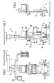
- Fig. 1 eine Vorderansicht des Deckenstatives mit aufgenommenem Narkosegerät;
- Fig. 2 eine Seitenansicht des Deckenstatives mit aufgenommenem Narkosegerät, wobei die abgesenkte Stellung gestrichelt und die angehobene Stellung in durchgezogenen Linien gezeichnet ist und;
- Fig. 3 einen Teil des in Fig. 2 in Seitenansicht gezeigten Deckenstativs mit hochgeklappten Schienen.
- Das Deckenstativ 1 weist einen an einer Decke 2 über ein Gelenk zu befestigenden Ausleger 3 und eine mit diesem gelenkig verbundene Säule 4 auf. Die Säule 4 weist einen mit dem Ausleger 3 verbundenen ersten Abschnitt 5 und einen zweiten Abschnitt 6 auf. Am bodenseitigen Ende des zweiten Abschnittes 6 ist eine Geräteaufnahmeeinrichtung 7 vorgesehen, diese weist am bodenseitigen Ende ein sich quer zu dem sich in vertikaler Richtung erstreckenden zweiten Abschnitt erstreckendes Joch auf. Wie insbesondere aus den Figuren 2 und 3 ersichtlich ist, ist an dem Joch ein sich in Arbeitsstellung in horizontaler Richtung erstreckendes Schienenpaar 9, 10 angeordnet. Die Verbindung zwischen Joch und den Schienen erfolgt über ein jeweiliges Drehgelenk 11 derart, daß die Schienen in Ruhestellung in der in Fig. 3 ersichtlichen Weise nach oben einklappbar sind.
- In dem gezeigten Ausführungsbeispiel weist der zweite Abschnitt 6 eine Zahnstange 12 und eine das Joch tragende Spindel 13 auf. Dadurch ist die Geräteaufnahmeeinrichtung durch Betätigen der Spindel in Richtung des Pfeiles 14 zwischen der in Fig. 2 in durchgezogenen Linien gezeigten Arbeitsstellung und der in gestrichelten Linien gezeigten abgesenkten Stellung auf- und abbewegbar. Dabei erfolgt die Höhenverstellung bevorzugt über eine Handkurbel, was den Vorteil hat, daß keine Kontaktleisten oder ähnliche Sicherheitseinrichtungen erforderlich sind. Anstelle des handbetätigten Höhenverstellmechanismus kann die Höhenverstellung alternativ auch über einen motorischen Antrieb erfolgen.
- Die Schienen 9, 10 sind über eine in Fig. 1 nur schematisch dargestellte Führung an dem Joch 8 in horizontaler Richtung entgegengesetzt zueinander ausfahrbar bzw. zueinander einfahrbar derart, daß der Abstand zwischen den beiden Schienen von einer in Fig. 1 in durchgezogenen Linien gezeigten engeren Stellung bis zu einer gestrichelt angedeuteten weiter auseinanderliegenden Stellung hin- und herfahrbar sind, wie dies durch die Pfeile in Fig. 1 angedeutet ist. Dadurch wird erreicht, daß eine breitenmäßige Anpassung der Schiene an verschiedenste Radabstände von Transportwagen aufweisenden Einrichtungen möglich ist.
- Die Schienen weisen sowohl auf der dem Joch zugewandten Seite als auch auf der Seite des freien Endes eine Mehrzahl von in Richtung der Schiene einen Abstand voneinander aufweisenden Bohrungen 15, 16 auf, die dazu dienen, sich quer über die jeweilige Schiene erstreckende Stifte aufzunehmen, die die Bewegung eines auf den Schienen aufgestellten Wagens 17 mit von diesem getragenen Gerät 18 zu blockieren.
- In einer Höhe, die sich oberhalb eines sich in Arbeitsstellung befindenden Narkosegerätes 18 erstreckt, ist ein erster Monitorträger 10 vorgesehen, der zur Aufnahme eines ersten Monitors 20 dient. Der Monitorträger ist über eine entsprechende Spindel 21 auf der Zahnstange 12 in Richtung des Pfeiles 22 unabhängig von der Höhe der Geräteaufnahmeeinrichtung 7 höhenverstellbar. Sowohl die Geräteaufnahmeeinrichtung 7 als auch der erste Monitorträger sind ferner in der durch die in Fig. 2 gezeigten Pfeile angedeuteten Weise um die Säulenachse schwenkbar. Das Stativ trägt einen zweiten Monitorträger 23, der mit dem ersten Abschnitt 5 der Säule bezüglich der axialen Richtung der Säule fest verbunden ist. Der erste Monitorträger 19 kann alternativ auch mit dem ersten Abschnitt 5 der Säule verbunden sein.
- Im Betrieb sind die beiden Monitore 20 und 24 bezüglich ihrer Neigung des Bildschirmes zu dem Arbeitsplatz passend in ihrer Neigung eingestellt. Das Narkosegerät 18 mit seinem Wagen 17 ist auf den Schienen 9, 10 mit Hilfe der Verriegelungsstifte ortsfest gehalten und über die Spindel 13 soweit nach oben gefahren, daß Bodenfreiheit besteht, so daß auch das Narkosegerät um die Achse des zweiten Abschnittes schwenkbar ist. Das Narkosegerät wird mit den durch den ortsfesten ersten Abschnitt der Säule geführten und hier nicht gezeigten Versorgungsleitungen verbunden.
- Soll das Narkosegerät zu einem anderen Einsatzort bewegt werden, wird die Geräteaufnahmeeinrichtung die in Fig. 2 gestrichelt dargestellte Stellung zum Boden abgesenkt. Dann wird das Gerät mit dem Wagen weggefahren. Gewünschtenfalls kann dasselbe oder ein anderes Gerät jederzeit wieder auf die Schienen gefahren werden. Hat der Wagen eines anderen Gerätes einen anderen Radabstand, werden die Schienen zur Anpassung an denselben seitlich verschoben. Nach der Aufnahme des Wagens wird dieser wiederum in die durchgezogen gezeigte Stellung angehoben. Wird kein Wagen aufgenommen, werden die Schienen in die in Fig. 3 gezeigte Stellung nach oben geklappt. Weder zur Abgabe eines Gerätes noch zur Aufnahme eines neuen Gerätes ist es erforderlich, die übrigen Geräte in ihrer Höhenstellung zu verändern. Das ist wesentlich, weil es dadurch vermieden wird, daß die einmal für den Arbeitsplatz günstig eingestellten Monitore jeweils wieder neu in ihrer Neigung einzujustieren sind.
Claims (10)
und mit einer ersten Geräteaufnahmeeinrichtung (7),
dadurch gekennzeichnet, daß die Geräteaufnahmeeinrichtung (7) derart höhenverstellbar ausgebildet ist, daß die Geräteaufnahmeeinrichtung (7) ein von einem Fahrgestell getragenes medizinisches Gerät (18) durch Untergreifen des Fahrgestelles aufnimmt.
dadurch gekennzeichnet, daß die Säule einen mit dem Ausleger (3) verbundenen ersten Abschnitt (5) und einen die Geräteaufnahmeeinrichtung (7) am bodenseitigen Ende aufweisenden zweiten Abschnitt (6) aufweist und der Abstand der Geräteaufnahmeeinrichtung zum ersten Abschnitt einstellbar ist.
dadurch gekennzeichnet, daß an der Säule ein Monitorträger (19) vorgesehen ist.
dadurch gekennzeichnet, daß der Abstand zwischen Geräteaufnahmeeinrichtung (7) und Monitorträger (19) einstellbar ist.
dadurch gekennzeichnet, daß die Geräteaufnahmeeinrichtung zwei in ihrem Abstand zueinander einstellbare Schienen (9, 10) aufweist.
dadurch gekennzeichnet, daß die Schienen (9, 10) zur Aufnahme von Laufrollen des Fahrgestelles ausgebildet sind.
dadurch gekennzeichnet, daß an den Schienen (9, 10) eine einstellbare Tiefenbegrenzung vorgesehen ist.
dadurch gekennzeichnet, daß eine das Fahrgestell in einer vorgegebenen Stellung haltende Verriegelungseinrichtung vorgesehen ist.
dadurch gekennzeichnet, daß die Schienen (9, 10) um einen am säulenseitigen Ende liegenden Drehpunkt (11) hochklappbar sind.
dadurch gekennzeichnet, daß die Schienen (9, 10) an einem sich quer zu dem zweiten Abschnitt aufweisenden Joch (8) befestigt sind.
Priority Applications (1)
| Application Number | Priority Date | Filing Date | Title |
|---|---|---|---|
| AT88120738T ATE95902T1 (de) | 1987-12-23 | 1988-12-12 | Deckenstativ zur aufnahme von medizinischen geraeten. |
Applications Claiming Priority (2)
| Application Number | Priority Date | Filing Date | Title |
|---|---|---|---|
| DE8716928U DE8716928U1 (de) | 1987-12-23 | 1987-12-23 | |
| DE8716928U | 1987-12-23 |
Publications (3)
| Publication Number | Publication Date |
|---|---|
| EP0321822A2 true EP0321822A2 (de) | 1989-06-28 |
| EP0321822A3 EP0321822A3 (en) | 1990-12-05 |
| EP0321822B1 EP0321822B1 (de) | 1993-10-13 |
Family
ID=6815443
Family Applications (1)
| Application Number | Title | Priority Date | Filing Date |
|---|---|---|---|
| EP88120738A Expired - Lifetime EP0321822B1 (de) | 1987-12-23 | 1988-12-12 | Deckenstativ zur Aufnahme von medizinischen Geräten |
Country Status (6)
| Country | Link |
|---|---|
| US (1) | US4993683A (de) |
| EP (1) | EP0321822B1 (de) |
| JP (1) | JPH01204665A (de) |
| AT (1) | ATE95902T1 (de) |
| DE (2) | DE8716928U1 (de) |
| NO (1) | NO885724L (de) |
Cited By (3)
| Publication number | Priority date | Publication date | Assignee | Title |
|---|---|---|---|---|
| WO1999025302A1 (de) * | 1997-11-18 | 1999-05-27 | Kreuzer Gmbh & Co. Ohg | Operationseinrichtung |
| DE10063208C1 (de) * | 2000-12-19 | 2002-05-29 | Draeger Medical Ag | Gerätewagen zum Andocken an eine Versorgungseinheit |
| CN113180968A (zh) * | 2021-04-27 | 2021-07-30 | 山东铭泰医疗设备集团有限公司 | 可移动方舱野战应急多功能吊塔工作站装置 |
Families Citing this family (50)
| Publication number | Priority date | Publication date | Assignee | Title |
|---|---|---|---|---|
| US5299338A (en) * | 1988-01-15 | 1994-04-05 | Hill-Rom Company, Inc. | Hospital bed with pivoting headboard |
| US5072906A (en) * | 1988-01-15 | 1991-12-17 | Hill-Rom Company, Inc. | Hospital bed with pivoting headboard |
| DE3916976A1 (de) * | 1989-05-24 | 1990-11-29 | Kreuzer F M K Gmbh | System mit einem ausleger zum aufnehmen von auf laufrollen gelagerten gegenstaenden |
| DE3937518A1 (de) * | 1989-11-10 | 1991-05-16 | Kreuzer F M K Gmbh | Geraetetraeger |
| DE4039550A1 (de) * | 1990-12-11 | 1992-06-17 | Kreuzer Gmbh & Co Ohg | Geraetewagen |
| ATE170084T1 (de) * | 1992-04-15 | 1998-09-15 | Hill Rom Co Inc | Halter für ein intravenöses infusionssystem |
| US5400995A (en) * | 1992-04-15 | 1995-03-28 | Hill-Rom Company, Inc. | IV pole with interior drag brake |
| US5400991A (en) * | 1992-11-19 | 1995-03-28 | Minnesota Mining And Manufacturing Company | Modular mounting assembly |
| US5319816A (en) * | 1992-12-07 | 1994-06-14 | Hill-Rom Company, Inc. | IV rack transferrable from an IV stand to a hospital bed |
| AU3943695A (en) * | 1994-11-15 | 1996-06-06 | Agne Nilsson | Mounting device for hospital equipment, medical support service unit therefor and service mobil |
| US5898961A (en) * | 1995-06-07 | 1999-05-04 | Hill-Rom, Inc. | Mobile support unit and attachment mechanism for patient transport device |
| US6725483B2 (en) * | 1997-01-31 | 2004-04-27 | Hill-Rom Services, Inc. | Apparatus and method for upgrading a hospital room |
| US6196649B1 (en) * | 1998-01-15 | 2001-03-06 | Steris Corporation | Convertible surgical equipment and appliance support system |
| DE19807243C2 (de) * | 1998-02-20 | 2002-07-11 | Siemens Ag | Medizinischer Arbeitsplatz |
| DE29805019U1 (de) * | 1998-03-19 | 1998-05-07 | Kreuzer Gmbh & Co Ohg | Überwachungs- und Versorgungseinrichtung für Patienten |
| US6095468A (en) * | 1998-03-27 | 2000-08-01 | Hill-Rom, Inc. | Support arm for a service column |
| USD418603S (en) * | 1998-06-26 | 2000-01-04 | Hill-Rom, Inc. | Power column |
| FR2780766B1 (fr) | 1998-07-01 | 2000-08-04 | Alm | Ensemble constitue d'une structure-porteuse et d'un chariot de transport de materiel |
| CA2272040A1 (fr) | 1999-05-13 | 2000-11-13 | Ecole Polytechnique | Systeme de camera d'observation robotisee pour utilisation en salle d'operation |
| DE19928835C1 (de) * | 1999-06-24 | 2001-01-11 | Draeger Medizintech Gmbh | Bewegliche medizinische Versorgungsvorrichtung |
| AU2002309987A1 (en) * | 2001-05-25 | 2002-12-09 | Hill-Rom Services, Inc. | Modular patient room |
| CA2454243A1 (en) | 2001-08-03 | 2003-02-20 | Hill-Rom Services, Inc. | Patient point-of-care computer system |
| US20030076015A1 (en) * | 2001-10-19 | 2003-04-24 | Ehrenreich Kevin J. | Medical servicing system |
| EP1442246B1 (de) * | 2001-11-05 | 2005-05-11 | Steris Inc. | Medizinische aufhängevorrichtung mit zwei achsen |
| DE10211365B4 (de) * | 2002-03-14 | 2005-03-17 | Siemens Ag | Vorrichtung zur medizinischen Notversorgung eines Patienten |
| FR2838803B1 (fr) * | 2002-04-22 | 2004-08-06 | Alm | Structure suspendue de manutention d'un equipement medical |
| US7073765B2 (en) * | 2002-11-13 | 2006-07-11 | Hill-Rom Services, Inc. | Apparatus for carrying medical equipment |
| US7083150B2 (en) * | 2003-03-18 | 2006-08-01 | Hill-Rom Services, Inc. | Patient line management system |
| WO2004082553A2 (en) * | 2003-03-18 | 2004-09-30 | Hill-Rom Services, Inc. | Radial arm system for patient care equipment |
| FR2860132A1 (fr) * | 2003-09-25 | 2005-04-01 | Caudal Medical | Dispositif destine a etre fixe au plafond pour porter des equipements pour les mettre a disposition |
| WO2005037166A2 (en) * | 2003-10-13 | 2005-04-28 | Hill-Rom Services, Inc. | Brake system for patient care equipment support arm |
| US8051610B2 (en) * | 2004-09-22 | 2011-11-08 | Hill-Rom Services, Inc. | Patient flatwall system |
| US7770247B2 (en) * | 2005-05-02 | 2010-08-10 | Hill-Rom Services, Inc. | Brake system for wall arm |
| WO2008074157A1 (en) * | 2006-12-21 | 2008-06-26 | Cote Jocelyn | Medical support system |
| US8640391B2 (en) * | 2008-10-16 | 2014-02-04 | Hill-Rom Services, Inc. | Modular architectural room system |
| MX2012004462A (es) | 2009-10-16 | 2012-06-27 | Spacelabs Healthcare Llc | Tubo de flujo de luz mejorado. |
| EP2374439A3 (de) | 2010-04-09 | 2015-11-25 | Hill-Rom Services, Inc. | Patientenliege, Kommunikation und Kommunikationsvorrichtung |
| US9629566B2 (en) | 2011-03-11 | 2017-04-25 | Spacelabs Healthcare Llc | Methods and systems to determine multi-parameter managed alarm hierarchy during patient monitoring |
| GB2554303A (en) * | 2011-10-13 | 2018-03-28 | Spacelabs Healthcare Llc | Integrated, extendable anesthesia system |
| DE102012009639B4 (de) | 2012-05-15 | 2024-04-18 | Drägerwerk AG & Co. KGaA | Deckenversorgungseinheit |
| DE102012108263A1 (de) * | 2012-09-05 | 2014-03-06 | Karl Storz Gmbh & Co. Kg | Medizinischer Arbeitsplatz |
| US8522488B1 (en) | 2012-10-15 | 2013-09-03 | Hill-Rom Services, Inc. | Headwall with integral wall panel interface |
| US9539155B2 (en) | 2012-10-26 | 2017-01-10 | Hill-Rom Services, Inc. | Control system for patient support apparatus |
| US10474808B2 (en) | 2013-03-29 | 2019-11-12 | Hill-Rom Services, Inc. | Hospital bed compatibility with third party application software |
| DE102013006700B4 (de) * | 2013-04-18 | 2017-02-09 | Drägerwerk AG & Co. KGaA | Medizinisches Gerätesystem, medizinisches Gerät, bodengebundenes Gestell für ein medizinisches Gerät und Verfahren für die Umwandlung eines deckengebundenen medizinischen Geräts in ein medizinisches Gerätesystem |
| US10987026B2 (en) | 2013-05-30 | 2021-04-27 | Spacelabs Healthcare Llc | Capnography module with automatic switching between mainstream and sidestream monitoring |
| WO2015062368A1 (zh) * | 2013-10-29 | 2015-05-07 | 湖南太阳龙医疗科技有限公司 | 一种icu护理单元组合吊塔 |
| DE102014206412A1 (de) | 2014-04-03 | 2015-10-08 | Siemens Aktiengesellschaft | Vorrichtung zur Aufnahme eines Prüflings, Anordnung und Verfahren zur Prüfung eines Prüflings |
| TWM494780U (zh) * | 2014-09-23 | 2015-02-01 | Kelly Internat Corp | 具支撐之昇降活動裝置 |
| CN111110494B (zh) * | 2020-01-22 | 2021-04-20 | 郝洪立 | 一种多用途变换的医用吊塔 |
Citations (3)
| Publication number | Priority date | Publication date | Assignee | Title |
|---|---|---|---|---|
| DE3312137A1 (de) * | 1983-04-02 | 1984-10-11 | Wella Ag, 6100 Darmstadt | Deckenstativ, insbesondere als traeger fuer medizinisch-technische geraete und dergl. |
| US4645156A (en) * | 1981-11-09 | 1987-02-24 | Karapita Alexander D | Suspension system |
| EP0257299A2 (de) * | 1986-08-13 | 1988-03-02 | Kreuzer GmbH + Co. OHG | Deckenstativ |
Family Cites Families (13)
| Publication number | Priority date | Publication date | Assignee | Title |
|---|---|---|---|---|
| US488608A (en) * | 1892-12-27 | Half to harrt c | ||
| GB630472A (en) * | 1947-11-18 | 1949-10-13 | Curran John Ltd | Improvements in or relating to engine test benches |
| US2663929A (en) * | 1952-03-27 | 1953-12-29 | Lester M Carpenter | Radiator bench |
| US2991966A (en) * | 1959-04-06 | 1961-07-11 | Daniel W Varel | Telescoping mast and elevator mechanism for stabilizing drill unit |
| US3269681A (en) * | 1965-01-27 | 1966-08-30 | Wakeem R Azim | Adjustable support apparatus |
| US3556455A (en) * | 1968-06-24 | 1971-01-19 | Fred Storm Ind Designs Inc | Overhead equipment control apparatus for operating rooms |
| DE1797040B2 (de) * | 1968-08-07 | 1972-02-10 | Original Hanau Quarzlampen Gmbh, 6450 Hanau | Aufhaengung fuer eine operationsleuchte |
| US3464655A (en) * | 1968-10-11 | 1969-09-02 | Albert Schuman | Concrete core drill |
| CA892291A (en) * | 1970-04-10 | 1972-02-01 | Atomic Energy Of Canada Limited, Commercial Products | Overhead isocentric couch for therapy equipment |
| US4234155A (en) * | 1978-10-19 | 1980-11-18 | Destree Allen L | Tool stand |
| US4673154A (en) * | 1983-07-05 | 1987-06-16 | Karapita Alexander D | Suspension device |
| US4599034A (en) * | 1984-12-31 | 1986-07-08 | Kennedy Donald L | Vehicle lift |
| US4759684A (en) * | 1987-01-16 | 1988-07-26 | Amerigo Lanzillotta | Wheelchair lift |
-
1987
- 1987-12-23 DE DE8716928U patent/DE8716928U1/de not_active Expired
-
1988
- 1988-12-12 EP EP88120738A patent/EP0321822B1/de not_active Expired - Lifetime
- 1988-12-12 AT AT88120738T patent/ATE95902T1/de not_active IP Right Cessation
- 1988-12-12 DE DE88120738T patent/DE3884926D1/de not_active Expired - Fee Related
- 1988-12-15 JP JP63317582A patent/JPH01204665A/ja active Pending
- 1988-12-20 US US07/287,858 patent/US4993683A/en not_active Expired - Fee Related
- 1988-12-22 NO NO88885724A patent/NO885724L/no unknown
Patent Citations (3)
| Publication number | Priority date | Publication date | Assignee | Title |
|---|---|---|---|---|
| US4645156A (en) * | 1981-11-09 | 1987-02-24 | Karapita Alexander D | Suspension system |
| DE3312137A1 (de) * | 1983-04-02 | 1984-10-11 | Wella Ag, 6100 Darmstadt | Deckenstativ, insbesondere als traeger fuer medizinisch-technische geraete und dergl. |
| EP0257299A2 (de) * | 1986-08-13 | 1988-03-02 | Kreuzer GmbH + Co. OHG | Deckenstativ |
Cited By (3)
| Publication number | Priority date | Publication date | Assignee | Title |
|---|---|---|---|---|
| WO1999025302A1 (de) * | 1997-11-18 | 1999-05-27 | Kreuzer Gmbh & Co. Ohg | Operationseinrichtung |
| DE10063208C1 (de) * | 2000-12-19 | 2002-05-29 | Draeger Medical Ag | Gerätewagen zum Andocken an eine Versorgungseinheit |
| CN113180968A (zh) * | 2021-04-27 | 2021-07-30 | 山东铭泰医疗设备集团有限公司 | 可移动方舱野战应急多功能吊塔工作站装置 |
Also Published As
| Publication number | Publication date |
|---|---|
| JPH01204665A (ja) | 1989-08-17 |
| ATE95902T1 (de) | 1993-10-15 |
| NO885724D0 (no) | 1988-12-22 |
| NO885724L (no) | 1989-06-26 |
| DE3884926D1 (de) | 1993-11-18 |
| EP0321822B1 (de) | 1993-10-13 |
| DE8716928U1 (de) | 1989-04-27 |
| EP0321822A3 (en) | 1990-12-05 |
| US4993683A (en) | 1991-02-19 |
Similar Documents
| Publication | Publication Date | Title |
|---|---|---|
| EP0321822B1 (de) | Deckenstativ zur Aufnahme von medizinischen Geräten | |
| EP0405234B1 (de) | Mobiles Röntgengerät | |
| EP3431421B1 (de) | Bediengerät für eine kommissioniervorrichtung | |
| EP0943306B1 (de) | Überwachungs- und Versorgungseinrichtung für Patienten | |
| DE3916976C2 (de) | ||
| EP0100492B1 (de) | Zahnärztlicher Patientenstuhl | |
| DE1474238B2 (de) | Vorrichtung zum bodenfreien abstuetzen einer schweren rolle | |
| EP3645433B1 (de) | Transportvorrichtung und verfahren zum tauchlackieren | |
| EP3609834B1 (de) | Hebebühne | |
| DE3049687T1 (de) | Vertically movable platform | |
| DE19536664C2 (de) | Computertisch | |
| DE2509805B2 (de) | Stichlochbohr- oder stopfmaschine fuer schacht-, insbesondere hochoefen | |
| DE4444003A1 (de) | Flaschenwagen zum Transport von Stahlflaschen | |
| DE10223897A1 (de) | Werkzeugwechselvorrichtung für Pressen | |
| DE3742813C2 (de) | ||
| DE1456538A1 (de) | Vorrichtung zur auswechselbaren Halterung von Arbeitsgeraeten an Lademaschinen | |
| EP0955409A1 (de) | Schienenverladewagen | |
| EP0878251A1 (de) | Transferpresse mit seitlicher Haltemittelablage an einem bewegbaren Pressentisch | |
| DE4034284A1 (de) | Vorrichtung zum schneiden von hecken mittels heckenschere | |
| DE3844317C2 (de) | ||
| CH687784A5 (de) | Geraetetragkonsole fuer Arbeits- und Kommandopulte oder fuer Schreibtische. | |
| AT390022B (de) | Maschine zum gleichzeitigen schweissen an beiden seiten einer rippe | |
| DE3636898C1 (en) | Stand with at least one adjustable standing area for a visual display unit | |
| DE10162047C1 (de) | Platinenhandlinggerät, insbesondere zum Einlegen von Blechplatinen in eine Presse | |
| EP0413904A1 (de) | Arbeitstisch |
Legal Events
| Date | Code | Title | Description |
|---|---|---|---|
| PUAI | Public reference made under article 153(3) epc to a published international application that has entered the european phase |
Free format text: ORIGINAL CODE: 0009012 |
|
| AK | Designated contracting states |
Kind code of ref document: A2 Designated state(s): AT BE DE FR IT NL SE |
|
| PUAL | Search report despatched |
Free format text: ORIGINAL CODE: 0009013 |
|
| AK | Designated contracting states |
Kind code of ref document: A3 Designated state(s): AT BE DE FR IT NL SE |
|
| RHK1 | Main classification (correction) |
Ipc: F16M 11/24 |
|
| 17P | Request for examination filed |
Effective date: 19910524 |
|
| 17Q | First examination report despatched |
Effective date: 19920728 |
|
| RAP1 | Party data changed (applicant data changed or rights of an application transferred) |
Owner name: KREUZER GMBH + CO. OHG |
|
| GRAA | (expected) grant |
Free format text: ORIGINAL CODE: 0009210 |
|
| AK | Designated contracting states |
Kind code of ref document: B1 Designated state(s): AT BE DE FR IT NL SE |
|
| PG25 | Lapsed in a contracting state [announced via postgrant information from national office to epo] |
Ref country code: NL Effective date: 19931013 Ref country code: IT Free format text: LAPSE BECAUSE OF FAILURE TO SUBMIT A TRANSLATION OF THE DESCRIPTION OR TO PAY THE FEE WITHIN THE PRE;WARNING: LAPSES OF ITALIAN PATENTS WITH EFFECTIVE DATE BEFORE 2007 MAY HAVE OCCURRED AT ANY TIME BEFORE 2007. THE CORRECT EFFECTIVE DATE MAY BE DIFFERENT FROM THE ONE RECORDED.SCRIBED TIME-LIMIT Effective date: 19931013 Ref country code: SE Effective date: 19931013 Ref country code: BE Effective date: 19931013 |
|
| REF | Corresponds to: |
Ref document number: 95902 Country of ref document: AT Date of ref document: 19931015 Kind code of ref document: T |
|
| REF | Corresponds to: |
Ref document number: 3884926 Country of ref document: DE Date of ref document: 19931118 |
|
| ET | Fr: translation filed | ||
| PG25 | Lapsed in a contracting state [announced via postgrant information from national office to epo] |
Ref country code: AT Effective date: 19931212 |
|
| NLV1 | Nl: lapsed or annulled due to failure to fulfill the requirements of art. 29p and 29m of the patents act | ||
| PLBI | Opposition filed |
Free format text: ORIGINAL CODE: 0009260 |
|
| 26 | Opposition filed |
Opponent name: DRAEGERWERK AKTIENGESELLSCHAFT Effective date: 19940705 |
|
| PGFP | Annual fee paid to national office [announced via postgrant information from national office to epo] |
Ref country code: FR Payment date: 19941215 Year of fee payment: 7 |
|
| PGFP | Annual fee paid to national office [announced via postgrant information from national office to epo] |
Ref country code: DE Payment date: 19941219 Year of fee payment: 7 |
|
| PLBN | Opposition rejected |
Free format text: ORIGINAL CODE: 0009273 |
|
| STAA | Information on the status of an ep patent application or granted ep patent |
Free format text: STATUS: OPPOSITION REJECTED |
|
| 27O | Opposition rejected |
Effective date: 19950605 |
|
| PG25 | Lapsed in a contracting state [announced via postgrant information from national office to epo] |
Ref country code: FR Effective date: 19960830 |
|
| PG25 | Lapsed in a contracting state [announced via postgrant information from national office to epo] |
Ref country code: DE Effective date: 19960903 |
|
| REG | Reference to a national code |
Ref country code: FR Ref legal event code: ST |