EP0322070A1 - Light valve projection system with non imaging optics for illumination - Google Patents
Light valve projection system with non imaging optics for illumination Download PDFInfo
- Publication number
- EP0322070A1 EP0322070A1 EP88202958A EP88202958A EP0322070A1 EP 0322070 A1 EP0322070 A1 EP 0322070A1 EP 88202958 A EP88202958 A EP 88202958A EP 88202958 A EP88202958 A EP 88202958A EP 0322070 A1 EP0322070 A1 EP 0322070A1
- Authority
- EP
- European Patent Office
- Prior art keywords
- reflector
- display system
- light source
- light
- images
- Prior art date
- Legal status (The legal status is an assumption and is not a legal conclusion. Google has not performed a legal analysis and makes no representation as to the accuracy of the status listed.)
- Granted
Links
Images


Classifications
-
- G—PHYSICS
- G09—EDUCATION; CRYPTOGRAPHY; DISPLAY; ADVERTISING; SEALS
- G09F—DISPLAYING; ADVERTISING; SIGNS; LABELS OR NAME-PLATES; SEALS
- G09F9/00—Indicating arrangements for variable information in which the information is built-up on a support by selection or combination of individual elements
-
- H—ELECTRICITY
- H04—ELECTRIC COMMUNICATION TECHNIQUE
- H04N—PICTORIAL COMMUNICATION, e.g. TELEVISION
- H04N9/00—Details of colour television systems
- H04N9/12—Picture reproducers
- H04N9/31—Projection devices for colour picture display, e.g. using electronic spatial light modulators [ESLM]
- H04N9/3102—Projection devices for colour picture display, e.g. using electronic spatial light modulators [ESLM] using two-dimensional electronic spatial light modulators
- H04N9/3105—Projection devices for colour picture display, e.g. using electronic spatial light modulators [ESLM] using two-dimensional electronic spatial light modulators for displaying all colours simultaneously, e.g. by using two or more electronic spatial light modulators
-
- G—PHYSICS
- G02—OPTICS
- G02B—OPTICAL ELEMENTS, SYSTEMS OR APPARATUS
- G02B19/00—Condensers, e.g. light collectors or similar non-imaging optics
- G02B19/0004—Condensers, e.g. light collectors or similar non-imaging optics characterised by the optical means employed
- G02B19/0028—Condensers, e.g. light collectors or similar non-imaging optics characterised by the optical means employed refractive and reflective surfaces, e.g. non-imaging catadioptric systems
-
- G—PHYSICS
- G02—OPTICS
- G02B—OPTICAL ELEMENTS, SYSTEMS OR APPARATUS
- G02B19/00—Condensers, e.g. light collectors or similar non-imaging optics
- G02B19/0033—Condensers, e.g. light collectors or similar non-imaging optics characterised by the use
- G02B19/0038—Condensers, e.g. light collectors or similar non-imaging optics characterised by the use for use with ambient light
- G02B19/0042—Condensers, e.g. light collectors or similar non-imaging optics characterised by the use for use with ambient light for use with direct solar radiation
-
- G—PHYSICS
- G02—OPTICS
- G02B—OPTICAL ELEMENTS, SYSTEMS OR APPARATUS
- G02B19/00—Condensers, e.g. light collectors or similar non-imaging optics
- G02B19/0033—Condensers, e.g. light collectors or similar non-imaging optics characterised by the use
- G02B19/0047—Condensers, e.g. light collectors or similar non-imaging optics characterised by the use for use with a light source
-
- H—ELECTRICITY
- H04—ELECTRIC COMMUNICATION TECHNIQUE
- H04N—PICTORIAL COMMUNICATION, e.g. TELEVISION
- H04N9/00—Details of colour television systems
- H04N9/12—Picture reproducers
- H04N9/31—Projection devices for colour picture display, e.g. using electronic spatial light modulators [ESLM]
- H04N9/3141—Constructional details thereof
- H04N9/315—Modulator illumination systems
- H04N9/3152—Modulator illumination systems for shaping the light beam
-
- H—ELECTRICITY
- H04—ELECTRIC COMMUNICATION TECHNIQUE
- H04N—PICTORIAL COMMUNICATION, e.g. TELEVISION
- H04N9/00—Details of colour television systems
- H04N9/12—Picture reproducers
- H04N9/31—Projection devices for colour picture display, e.g. using electronic spatial light modulators [ESLM]
- H04N9/3141—Constructional details thereof
- H04N9/315—Modulator illumination systems
- H04N9/3164—Modulator illumination systems using multiple light sources
Definitions
- the present invention relates to a display system having at least one light channel, each channel comprising an illumination system, a rectangular modulating device in the path of light emitted by said illumination system, and a projection lens for projecting the image of said modulating device.
- a projection system including an illumination subsystem, a modulating device in the path of light emitted from the illumination subsystem, and a projection lens for projecting the image of the modulating device. More specifically, an illumination subsystem in the form of a halogen lamp and a spherical reflector projects light through a condenser lens to a pair of dichroic mirrors which split the light into its red, blue, and green components.
- Each beam component impinges a respective modulating device in the form of a liquid crystal display (LCD); a dichroic prism combines the three monochromatic images into a single color image which the projection lens projects onto a screen.
- LCD liquid crystal display
- a dichroic prism combines the three monochromatic images into a single color image which the projection lens projects onto a screen.
- the article states that the system offers the advantages of compactness, low cost, and brightness. Despite the latter claim, though, the overall light collection efficiency of the system is still less than 1%. That is, for a tungsten halide lamp producing 8800 lumens, less than 60 lumens reach the projection screen. This low efficiency is largely due to the fact that only a small percentage of the light rays is collected and directed toward the modulating device and the entrance pupil of the projection lens.
- fill factor further diminishes efficiency. For example, for an LCD having a 4 to 3 aspect ratio, only 61% of a circumscribing circle representing the light beam is filled by the LCD. For a 5.33 to 3 aspect ratio as proposed for high definition television, the fill factor is only 54%.
- the present invention provides such illumination system which is characterized in that said illumination system comprises a non-imaging reflector having a rectangular output aperture and a central Z axis, a light source being positioned inside the reflector along the central axis for illuminating said modulating output aperture, said reflector cooperating with said light source to illuminate said modulating device at least substantially uniformly.
- a typical non-imaging concentrator is a trough-shaped reflector with an input aperture and a pair of opposed sidewalls which converge toward a closed end.
- the sidewalls are configured to concentrate incident energy onto an energy receiver such as a photo-voltaic cell or a fluid carrying pipe positioned inside the reflector.
- an energy receiver such as a photo-voltaic cell or a fluid carrying pipe positioned inside the reflector.
- Such a concentrator is discussed in U.S. Patent No. 4,002,499, which teaches a concentrator configured for optimal concentration of radiant energy on a cylindrical absorber such as a pipe.
- U.S. Patent No. 4,230,095 discloses the ideal profile for a trough-shaped concentrator with a gap between the absorber and the reflector. This is the situation for a pipe concentrically located within a transparent glazing, and utilizes symmetric sidewalls which meet at a cusp which contacts the glazing.
- the solar concentrators offer the advantage that all light within a predetermined angle of acceptance is focussed onto the energy absorber. The wider the angle of acceptance, the larger the absorber must be. Likewise, the angle of acceptance is more narrowly confined for a smaller absorber, resulting in greater light concentration. Concentrators with small acceptance angles require solar tracking the achieve absorption over more hours in a day.
- non-imaging reflectors heretofore used primarily in solar energy concentrators
- the deviation angle of the light at the output aperture of collector in the form of a non-imaging reflector thus has a well defined limit, just as the input in a concentrator has a well defined field of acceptance.
- the collector may thus be designed in conjunction with a given lamp to minimize deviation angle, making it possible to maximize efficiency when used in a projection system.
- the light source is substantially cylindrical and is centered in an XY plane of a three axes (XYZ) coordinate system, said light source having an arc with a length along the Y-axis and a radius along the X-axis, and further includes a cylindrical envelope concentric to the arc, the cross-section of the reflector in the XY plane is at least substantially rectangular.
- the cross-section in YZ plane comprises a compound parabola.
- the cross-section in the XZ plane is preferably trough-shaped, with two symmetric sidewalls which meet at a cusp in contact with the envelope, and has an ideal contour determined with respect to a virtual arc shape defined by the actual arc and two lines tangent thereto which intersect at the cusp.
- the display system is especially useful in a projection color television system having three illumination subsystems according to the preferred embodiment, where the respective lamps are spectrally turned to the red, green, and blue wavelengths and the modulating devices are liquid crystal displays (LCDs).
- LCDs liquid crystal displays
- Such a system must further comprise means for combining the images of the LCDs for projection by the lens.
- Such means could comprise a dichroic prism or a pair of dichroic filters.
- the display system could also find use in a television projection system with only a single illumination subsystem according to the preferred embodiment, and a pair of dichroic filters for separating the light into three channels.
- Three LCDs would be located in the paths of light in respective channels, and combining means such as additional filters or a prism would be used to combine the images for projection.
- the present invention relates to an illumination system used as the illumination subsystem in the display systems so far described. That is, an illumination system having a light source used with a non-imaging reflector having a rectangular output aperture and a central Z axis. The non-imaging reflector cooperates with the light source to illuminate the output aperture, and thus the modulating device, at least substantially uniformly.
- the light source is cylindrical.
- Non-imaging reflectors Other shapes of light sources and other forms of non-imaging reflectors than those described may be used to achieve substantially uniform illumination of the modulating device.
- Each form of non-imaging reflector has its own characteristics.
- the compound parabolic shape is especially suitable when uniform illumination of the output aperture is desired. This is the case when the modulating device is at the output aperture.
- some non-imaging reflectors can provide substantially homogeneous illumination in more remote planes.
- a compound elliptical reflector for example, can illuminate a plane remote from the output aperture substantially homogeneously. Thus, it may be suitable where the modulating device is remote from the output aperture.
- Figure 1a depicts a cylindrical light source 2 in a collector in the form of a non-imaging reflector 10 having a rectangular output aperture 20.
- a cylindrical light source 2 in a collector in the form of a non-imaging reflector 10 having a rectangular output aperture 20.
- the reflector it is superposed on a rectangular coordinate system with the Z-axis extending centrally through the reflector and the light source centered in the XY plane.
- the arc 5 is concentrally located in a cylindrical glass envelope 6 having a radius r2 in the vicinity of the arc 5.
- the length of the arc extends along the Y-axis and a radius extends along the X-axis.
- Figure 1b shows the profile of the top and bottom sidewalls 12 of the reflector, which profile is preferably a compound parabola to minimize the deviation angle ⁇ y , where ⁇ y is the maximum angle between the Z-axis and light rays exiting from output aperture 20.
- a compound parabola is achieved by rotating a parabolic shape 180° with its axis along line 25 about the reflector axis 26 (herein the Z-axis).
- This is the ideal reflector profile in the YZ plane and planes parallel thereto when the arc 5 extends from one sidewall 12 to the other.
- the ideal reflector profile parallel to the axis of a cylindrical light source is thus the same as the profile for a planar source as described in the companion case, wherein a light source outside the reflector is considered as a planar source at the input aperture of the collector.
- each sidewall 17 has three segments which define the ideal contour with respect to a virtual arc shape defined by lines tangent to the arc which intersect at the cusp.
- the first segment 15 of each sidewall is the involute of the virtual arc extending from the cusp to the line formed by a ray along line 28 as shown.
- the second or intermediate segment 16 follows the rule that rays emitted tangent to the virtual arc will have a maximum angle of ⁇ x with the Z-axis.
- This segment extends to the intersection of line 29 and the reflector.
- the segments 15 and 16 correspond to the shape of a reflector for a glazed cylindrical absorber as described in U.S. Patent No. 4,230,095, incorporated herein by reference.
- the third segment 17 is rectilinear in cross-section (planar in the reflector) and parallels the opposed 17 of the other sidewall 14.
- the segments 17 merely reflect light without increasing ⁇ x , and are necessary to extend the ideal reflector profile in the XZ plane to the output aperture. Where a longer reflector is desired without increasing the size of output aperture 20 the sidewalls 12 may likewise be extended in parallel, essentially forming a light pipe.
- Figure 3 shows the section through the XZ plane in greater detail, with the reflector profile defined in terms of ⁇ and ⁇ , where ⁇ is the length of a line tangent to the light source measured from the source to the collector, and ⁇ is the angle between the normal to the tangent line and the -Z-axis.
- Angles ⁇ B and ⁇ s measured with respect to the -Z-axis, define the start and end of segment 15 and ⁇ L defines to the end of the segment 16.
- ⁇ B and ⁇ s are the length of the tangent lines which define the begining and end of involute segment 15.
- ⁇ x is the length of the line which defines the end of segment 16.
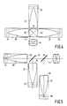
- Figure 4 shows three lamps 24, 30, and 36 which are spectrally used to the red, green, and blue portions of the visible spectrum. These are used in conjunction with respective non-imaging reflectors 26, 32, 38 to illuminate the LCDs 28, 34, 40. The red, green, and blue images on the LCDs are then combined by dichroic prism 42 for projection by lens 44.
- Figure 5 is another three lamp system wherein the images of LCDs 28 and 34 are combined by dichroic filter 46 then further combined with the image of LCD 40 by dichroic filter 48 for projection by lens 44.
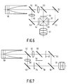
- Figure 6 shows a source of white light 50 which is divided into red, green, and blue channels by dichroic filters 52, 55 and reflected via mirrors 53 toward respective LCDs 54, 56, 57 then combined by prism 60 for projection by lens 61.
- Lenses 62 and 63 are used to image the output aperture of the non-imaging reflector to the LCDs.
- Figure 7 again shows a white light source 50 and dichroic filters 52, 55 to image the three channels onto respective LCDs but dichroic filters 58, 59 are used to combine the images for projection by lens 61.
Abstract
Description
- The present invention relates to a display system having at least one light channel, each channel comprising an illumination system, a rectangular modulating device in the path of light emitted by said illumination system, and a projection lens for projecting the image of said modulating device.
- The possibility of using liquid crystal displays in projection television is well accepted, and several systems have been proposed. In an article on pages 375-377 of the 1986 of Society of Information Display Digest, Seiko Corporation discloses a projection system including an illumination subsystem, a modulating device in the path of light emitted from the illumination subsystem, and a projection lens for projecting the image of the modulating device. More specifically, an illumination subsystem in the form of a halogen lamp and a spherical reflector projects light through a condenser lens to a pair of dichroic mirrors which split the light into its red, blue, and green components. Each beam component impinges a respective modulating device in the form of a liquid crystal display (LCD); a dichroic prism combines the three monochromatic images into a single color image which the projection lens projects onto a screen. The article states that the system offers the advantages of compactness, low cost, and brightness. Despite the latter claim, though, the overall light collection efficiency of the system is still less than 1%. That is, for a tungsten halide lamp producing 8800 lumens, less than 60 lumens reach the projection screen. This low efficiency is largely due to the fact that only a small percentage of the light rays is collected and directed toward the modulating device and the entrance pupil of the projection lens.
- A further discussion of conventional illumination systems will be helpful. It is well known that a parabolic reflector with a point light source at that focal point of the parabola can provide collimated light beams, and thus offers a potentially high collection efficiency. However, lamps have finite source sizes which result in large deviation angles at the output aperture of a parabolic reflector. Even if a very small lamp is used, slight displacements from the focal point can result in additional deviation. Further, when the light valve and thus the reflector are small, it may be impossible to center the lamp at the focal point due to the finite envelope size. The most efficient refractive lens condensing systems are not as efficient (typically less than 43% efficiency) and require expensive multi-element lenses to limit deviation angles. In these refractive lens condensing systems, the envelope size of the lamp is not as important.
- Further, when either a parabolic reflector or a refractive lens condensing system is used with a rectangular light valve such as an LCD for TV pictures, "fill factor" further diminishes efficiency. For example, for an LCD having a 4 to 3 aspect ratio, only 61% of a circumscribing circle representing the light beam is filled by the LCD. For a 5.33 to 3 aspect ratio as proposed for high definition television, the fill factor is only 54%.
- From the foregoing it is apparent that it would be desirable to have a more highly efficient illumination system, that is, a system with far greater lumen output at the output of the reflector as a percentage of lumen output of the lamp. In order to improve the efficiency of the system as a whole, which is in the luminous flux at the projection screen as a percentage of lumen output of the lamp, it will also be necessary to keep the maximum deviation angle of light emitted by the illumination system to a minimum. For a large aperture F/2.0 projection lens, this maximum deviation angle would be 15°. Finally, since rectangular light valves in the form of LCDs will be used and it would be desirable to have a 100% fill factor, the illumination system should have a rectangular output aperture corresponding to the shape of the LCD.
- The present invention provides such illumination system which is characterized in that said illumination system comprises a non-imaging reflector having a rectangular output aperture and a central Z axis, a light source being positioned inside the reflector along the central axis for illuminating said modulating output aperture, said reflector cooperating with said light source to illuminate said modulating device at least substantially uniformly.
- The use of non-imaging optics to efficiently collect sunlight in solar energy applications is well known. See, for example, "The Optics of Non Imaging Concentrators", Welford and Winston, Academic Press, 1978. A typical non-imaging concentrator is a trough-shaped reflector with an input aperture and a pair of opposed sidewalls which converge toward a closed end. The sidewalls are configured to concentrate incident energy onto an energy receiver such as a photo-voltaic cell or a fluid carrying pipe positioned inside the reflector. Such a concentrator is discussed in U.S. Patent No. 4,002,499, which teaches a concentrator configured for optimal concentration of radiant energy on a cylindrical absorber such as a pipe. The sidewalls are symmetric and meet at a cusp which contacts the pipe. U.S. Patent No. 4,230,095, discloses the ideal profile for a trough-shaped concentrator with a gap between the absorber and the reflector. This is the situation for a pipe concentrically located within a transparent glazing, and utilizes symmetric sidewalls which meet at a cusp which contacts the glazing.
- The solar concentrators offer the advantage that all light within a predetermined angle of acceptance is focussed onto the energy absorber. The wider the angle of acceptance, the larger the absorber must be. Likewise, the angle of acceptance is more narrowly confined for a smaller absorber, resulting in greater light concentration. Concentrators with small acceptance angles require solar tracking the achieve absorption over more hours in a day.
- The invention recognizes that non-imaging reflectors, heretofore used primarily in solar energy concentrators, are ideal for a light projection system having a collector with an output aperture which corresponds to the input aperture of a concentrator and vice versa. The deviation angle of the light at the output aperture of collector in the form of a non-imaging reflector thus has a well defined limit, just as the input in a concentrator has a well defined field of acceptance. The collector may thus be designed in conjunction with a given lamp to minimize deviation angle, making it possible to maximize efficiency when used in a projection system. When the modulating device is a predetermined size, and if the modulating device is immediately adjacent the output aperture of the collector, the dimensions of the modulating device and the maximum deviation angle will determine the shape of the collector.
- According to a preferred embodiment the light source is substantially cylindrical and is centered in an XY plane of a three axes (XYZ) coordinate system, said light source having an arc with a length along the Y-axis and a radius along the X-axis, and further includes a cylindrical envelope concentric to the arc, the cross-section of the reflector in the XY plane is at least substantially rectangular. Preferably the cross-section in YZ plane comprises a compound parabola. The cross-section in the XZ plane is preferably trough-shaped, with two symmetric sidewalls which meet at a cusp in contact with the envelope, and has an ideal contour determined with respect to a virtual arc shape defined by the actual arc and two lines tangent thereto which intersect at the cusp.
- The display system is especially useful in a projection color television system having three illumination subsystems according to the preferred embodiment, where the respective lamps are spectrally turned to the red, green, and blue wavelengths and the modulating devices are liquid crystal displays (LCDs). Such a system must further comprise means for combining the images of the LCDs for projection by the lens. Such means could comprise a dichroic prism or a pair of dichroic filters.
- The display system could also find use in a television projection system with only a single illumination subsystem according to the preferred embodiment, and a pair of dichroic filters for separating the light into three channels. Three LCDs would be located in the paths of light in respective channels, and combining means such as additional filters or a prism would be used to combine the images for projection.
- In its broadest aspect the present invention relates to an illumination system used as the illumination subsystem in the display systems so far described. That is, an illumination system having a light source used with a non-imaging reflector having a rectangular output aperture and a central Z axis. The non-imaging reflector cooperates with the light source to illuminate the output aperture, and thus the modulating device, at least substantially uniformly. According to a preferred embodiment the light source is cylindrical.
- Other shapes of light sources and other forms of non-imaging reflectors than those described may be used to achieve substantially uniform illumination of the modulating device. Each form of non-imaging reflector has its own characteristics. For example, the compound parabolic shape is especially suitable when uniform illumination of the output aperture is desired. This is the case when the modulating device is at the output aperture. However, some non-imaging reflectors can provide substantially homogeneous illumination in more remote planes. A compound elliptical reflector, for example, can illuminate a plane remote from the output aperture substantially homogeneously. Thus, it may be suitable where the modulating device is remote from the output aperture.
- The invention will now be described with reference to the drawings, wherein:
- Figure 1a is a perspective of a non-imaging collector with a cylindrical light source;
- Figure 1b is a cross-section in the YZ plane of Figure 1a;
- Figure 1c is a cross-section in the XZ plane of Figure 1a;
- Figure 2 is an elevation view of a cylindrical light source;
- Figure 3 illustrates the mathematics of the collector profile of Figure 1c;
- Figure 4 is a plan view of a three lamp system with a dichroic prism;
- Figure 5 is a plan view of a three lamp system with two dichroic filters;
- Figure 6 is a plan view of a single lamp system with dichroic filters for color separation and a dichroic prism combining the images; and
- Figure 7 is a plan view of a single lamp system with dichroic filters for color separation and dichroic filters for combining the images.
- Figure 1a depicts a cylindrical
light source 2 in a collector in the form of anon-imaging reflector 10 having arectangular output aperture 20. For convenience in describing the reflector it is superposed on a rectangular coordinate system with the Z-axis extending centrally through the reflector and the light source centered in the XY plane. - Referring to Figure 2, the
light source 2 in an arc lamp such as a xenon arc lamp or a metal halide arc lamp having a pair ofelectrodes 4 for forming anarc 5 of length L and radius r₁ therebetween. Thearc 5 is concentrally located in acylindrical glass envelope 6 having a radius r₂ in the vicinity of thearc 5. Referring to Figures 1a, 1b, and 1c, the length of the arc extends along the Y-axis and a radius extends along the X-axis. - Figure 1b shows the profile of the top and
bottom sidewalls 12 of the reflector, which profile is preferably a compound parabola to minimize the deviation angle ϑy, where ϑy is the maximum angle between the Z-axis and light rays exiting fromoutput aperture 20. - A compound parabola is achieved by rotating a parabolic shape 180° with its axis along
line 25 about the reflector axis 26 (herein the Z-axis). This is the ideal reflector profile in the YZ plane and planes parallel thereto when thearc 5 extends from onesidewall 12 to the other. The ideal reflector profile parallel to the axis of a cylindrical light source is thus the same as the profile for a planar source as described in the companion case, wherein a light source outside the reflector is considered as a planar source at the input aperture of the collector. - It can be shown that:

- Referring to Figure 1c, the cross-section of the collector in the XZ plane and planes parallel thereto is bounded by
vertical sidewalls 17. Thesidewalls 17 are symmetric and meet at a cusp in contact with thelamp envelope 6. From a mathematic standpoint, eachsidewall 17 has three segments which define the ideal contour with respect to a virtual arc shape defined by lines tangent to the arc which intersect at the cusp. Thefirst segment 15 of each sidewall is the involute of the virtual arc extending from the cusp to the line formed by a ray alongline 28 as shown. The second orintermediate segment 16 follows the rule that rays emitted tangent to the virtual arc will have a maximum angle of ϑx with the Z-axis. This segment extends to the intersection ofline 29 and the reflector. Thesegments third segment 17 is rectilinear in cross-section (planar in the reflector) and parallels the opposed 17 of theother sidewall 14. Thesegments 17 merely reflect light without increasing ϑx, and are necessary to extend the ideal reflector profile in the XZ plane to the output aperture. Where a longer reflector is desired without increasing the size ofoutput aperture 20 thesidewalls 12 may likewise be extended in parallel, essentially forming a light pipe. - Figure 3 shows the section through the XZ plane in greater detail, with the reflector profile defined in terms of ρ and ϑ, where ρ is the length of a line tangent to the light source measured from the source to the collector, and ϑ is the angle between the normal to the tangent line and the -Z-axis. Note that:

segment 15 and ϑL defines to the end of thesegment 16. Similarly, ρB and ρs are the length of the tangent lines which define the begining and end ofinvolute segment 15. ρx is the length of the line which defines the end ofsegment 16. Here the light ray represented by ρx would exit the reflector were it not for the planar sections 17 (Figure 1c). Thus the first orinvolute section 15 may be defined by
ρ = (ϑ + ϑD)r₁ for ϑB < ϑ < ϑs
where ϑD is the overlap angle, i.e., the increment over ϑB which when added thereto would subtend an arc of length ρB. ϑD is given
X = r₁ sinϑ - ρ cosϑ
Z = r₁ cosϑ + ρ sinϑ - Based on the foregoing, it can be shown that for an output aperture 50mm by 67mm and a source with an arc length L of 6mm, an arc radius of r₁ of 0.5mm and an envelope radius of 5mm, ϑx = 9.9° and ϑY = 6.9°.
- Note that the above mathematics are found in the prior art, e.g. Winston and Welford, supra, and are given here solely for convenience. Note also that other non-imaging reflectors such as compound elliptical and compound hyperbolic concentrators can be used to achieve substantially uniform illumination of an output aperture while limiting the deviation angle of light emitted. Further, some reflectors such as the compound elliptical reflector are known to provide substantially uniform illumination of a plane remote from the output aperture. See, inter alia, Welford and Winston, Supra; Eichhorn, "Designing generalized conic concentrators for conventional optical systems". Applied Optics, Vol. 24 No. 8; U.S. Patent No. 3,957,031. Note also that other shaped sources could likewise be used to illuminate a rectangular output aperture. With a point or spherical source, for example, a cusp would be formed in both the XZ and the YZ planes.
- Thus it is not the geometry of non-imaging reflectors but the recognition of their usefulness in conjunction with internal light sources and projection systems which constitutes the invention. The beam of light emitted by an illumination system comprising a source with a non-imaging reflector yields sufficiently low deviation angles with respect to collimated light that a projection television system utilizing LCDs is feasible to manufacture. Several examples of such projection systems follow.
- Figure 4 shows three
lamps non-imaging reflectors LCDs dichroic prism 42 for projection bylens 44. Figure 5 is another three lamp system wherein the images ofLCDs dichroic filter 46 then further combined with the image ofLCD 40 bydichroic filter 48 for projection bylens 44. - Figure 6 shows a source of
white light 50 which is divided into red, green, and blue channels bydichroic filters mirrors 53 towardrespective LCDs prism 60 for projection bylens 61.Lenses white light source 50 anddichroic filters dichroic filters lens 61. - The foregoing is exemplary and not intended to limit the scope of the claims which follow.
Claims (11)
Applications Claiming Priority (2)
| Application Number | Priority Date | Filing Date | Title |
|---|---|---|---|
| US07/137,048 US4912614A (en) | 1987-12-23 | 1987-12-23 | Light valve projection system with non imaging optics for illumination |
| US137048 | 1987-12-23 |
Publications (2)
| Publication Number | Publication Date |
|---|---|
| EP0322070A1 true EP0322070A1 (en) | 1989-06-28 |
| EP0322070B1 EP0322070B1 (en) | 1994-03-16 |
Family
ID=22475605
Family Applications (1)
| Application Number | Title | Priority Date | Filing Date |
|---|---|---|---|
| EP88202958A Expired - Lifetime EP0322070B1 (en) | 1987-12-23 | 1988-12-19 | Light valve projection system with non imaging optics for illumination |
Country Status (5)
| Country | Link |
|---|---|
| US (1) | US4912614A (en) |
| EP (1) | EP0322070B1 (en) |
| JP (1) | JPH021888A (en) |
| KR (1) | KR970004239B1 (en) |
| DE (1) | DE3888493T2 (en) |
Cited By (11)
| Publication number | Priority date | Publication date | Assignee | Title |
|---|---|---|---|---|
| EP0456427A2 (en) * | 1990-05-08 | 1991-11-13 | Canon Kabushiki Kaisha | Polarization converting apparatus and optical instrument having the same |
| EP0500220A2 (en) * | 1991-02-18 | 1992-08-26 | Scitex Corporation Ltd. | Apparatus and method for separating transparencies |
| EP0509630A2 (en) * | 1991-02-21 | 1992-10-21 | DOLGOFF, Eugene | A high efficiency light valve projection system |
| FR2694103A1 (en) * | 1992-07-24 | 1994-01-28 | Thomson Csf | Color image projector. |
| US5749642A (en) * | 1992-03-18 | 1998-05-12 | Canon Kabushiki Kaisha | Illuminating optical system and projector utilizing the same |
| EP1148736A2 (en) * | 1992-05-06 | 2001-10-24 | Canon Kabushiki Kaisha | Image forming apparatus and projector using the same |
| EP1418765A1 (en) * | 2002-11-07 | 2004-05-12 | Sony International (Europe) GmbH | Illumination arrangement for a projection system |
| WO2004043076A2 (en) * | 2002-11-07 | 2004-05-21 | Sony International (Europe) Gmbh | Illumination arrangement for a projection system |
| EP1579251A1 (en) * | 2002-12-20 | 2005-09-28 | Koninklijke Philips Electronics N.V. | Apparatus and method for illuminating a rod |
| US7445340B2 (en) | 2005-05-19 | 2008-11-04 | 3M Innovative Properties Company | Polarized, LED-based illumination source |
| US7540616B2 (en) | 2005-12-23 | 2009-06-02 | 3M Innovative Properties Company | Polarized, multicolor LED-based illumination source |
Families Citing this family (26)
| Publication number | Priority date | Publication date | Assignee | Title |
|---|---|---|---|---|
| US5243459A (en) * | 1989-05-05 | 1993-09-07 | The Argonne National Laboratory | Nonimaging radiant energy device |
| JP2961807B2 (en) * | 1990-04-20 | 1999-10-12 | 三菱電機株式会社 | Projection display device |
| US5192962A (en) * | 1990-05-29 | 1993-03-09 | Pioneer Electronic Corporation | Converging reflector and liquid crystal display device |
| US5335152A (en) * | 1991-10-11 | 1994-08-02 | Nioptics Corporation | Nonimaging optical illumination system |
| US5289356A (en) * | 1991-07-19 | 1994-02-22 | Nioptics Corporation | Nonimaging optical illumination system |
| US5586013A (en) * | 1991-07-19 | 1996-12-17 | Minnesota Mining And Manufacturing Company | Nonimaging optical illumination system |
| US5253151A (en) * | 1991-09-30 | 1993-10-12 | Rockwell International Corporation | Luminaire for use in backlighting a liquid crystal display matrix |
| US5384659A (en) * | 1992-04-20 | 1995-01-24 | Mitsubishi Denki Kabushiki Kaisha | Condenser lens, polarizing element, light source apparatus, and projection display apparatus |
| US5278596A (en) * | 1992-05-19 | 1994-01-11 | Machtig Jeffrey S | LCD projection apparatus |
| JP3076678B2 (en) * | 1992-08-21 | 2000-08-14 | 松下電器産業株式会社 | Projection image display device |
| US5604607A (en) * | 1992-10-19 | 1997-02-18 | Eastman Kodak Company | Light concentrator system |
| WO1994012690A1 (en) * | 1992-11-25 | 1994-06-09 | John Beavis Lasich | The production of hydrogen from solar radiation at high efficiency |
| US5420655A (en) * | 1992-12-16 | 1995-05-30 | North American Philips Corporation | Color projection system employing reflective display devices and prism illuminators |
| US5467207A (en) * | 1994-07-06 | 1995-11-14 | Prolux Corporation | LCD projection system which aligns the larger beam spread angle of the light source with the larger acceptance angle of the light valve and a nonimaging reflector for an illumination system |
| US6269565B1 (en) | 1994-11-28 | 2001-08-07 | Smartlight Ltd. | Display device |
| IL119407A0 (en) * | 1995-11-24 | 1997-01-10 | Smartlight Limited | Local chromaticity correction |
| JPH11142780A (en) * | 1997-11-12 | 1999-05-28 | Mitsubishi Electric Corp | Light source device and projection type display device |
| US6364487B1 (en) * | 1999-01-29 | 2002-04-02 | Agilent Technologies, Inc. | Solid state based illumination source for a projection display |
| US20030218726A1 (en) * | 2002-05-23 | 2003-11-27 | Huibers Andrew G. | Light recapture projection system |
| WO2004097516A2 (en) * | 2003-04-24 | 2004-11-11 | Chromnomotion Imaging Applications, Inc. | Solid state light engine optical system |
| US7152977B2 (en) * | 2003-04-24 | 2006-12-26 | Qubic Light Corporation | Solid state light engine optical system |
| US20050219845A1 (en) * | 2004-02-09 | 2005-10-06 | Gregory Cutler | Illumination system with improved optical efficiency |
| US20050231958A1 (en) * | 2004-02-09 | 2005-10-20 | Gregory Cutler | Illumination system with improved optical efficiency |
| US20060139580A1 (en) * | 2004-12-29 | 2006-06-29 | Conner Arlie R | Illumination system using multiple light sources with integrating tunnel and projection systems using same |
| US9022298B2 (en) * | 2009-08-27 | 2015-05-05 | Reznor Llc | Radiant heat reflector and heat converter |
| CN111568369A (en) * | 2020-05-20 | 2020-08-25 | 上海理工大学 | Light source device of ophthalmology slit lamp microscope |
Citations (2)
| Publication number | Priority date | Publication date | Assignee | Title |
|---|---|---|---|---|
| EP0196959A1 (en) * | 1985-03-19 | 1986-10-08 | MALIFAUD, Pierre | Radiation projector device with a highly efficient and uniform flux in given aperture angles, in particular from a point or quasi point source |
| GB2191057A (en) * | 1986-05-19 | 1987-12-02 | Philips Electronic Associated | Colour video display arrangement |
Family Cites Families (12)
| Publication number | Priority date | Publication date | Assignee | Title |
|---|---|---|---|---|
| US2604005A (en) * | 1949-01-21 | 1952-07-22 | Charles A Hahn | Projection light source and light beam modifier combination |
| FR1602203A (en) * | 1968-07-19 | 1970-10-26 | ||
| US3798441A (en) * | 1972-10-16 | 1974-03-19 | Illumination Ind Inc | Illuminator for exposing color television tubes during the manufacturing process thereof and the like |
| US3827782A (en) * | 1972-12-11 | 1974-08-06 | Eprod Inc | Reflector apparatus |
| US4230095A (en) * | 1978-05-26 | 1980-10-28 | The United States Of America As Represented By The United States Department Of Energy | Ideal light concentrators with reflector gaps |
| US4368963A (en) * | 1978-06-29 | 1983-01-18 | Michael Stolov | Multicolor image or picture projecting system using electronically controlled slides |
| FR2465241A1 (en) * | 1979-09-10 | 1981-03-20 | Thomson Csf | ILLUMINATOR DEVICE FOR PROVIDING AN ADJUSTABLE INTENSITY DISTRIBUTION ILLUMINATION BEAM AND PATTERN TRANSFER SYSTEM COMPRISING SUCH A DEVICE |
| US4355350A (en) * | 1980-09-02 | 1982-10-19 | Polaroid Corporation | Reflector for use in an artificial lighting device |
| JPH068934B2 (en) * | 1982-01-11 | 1994-02-02 | オリンパス光学工業株式会社 | Luminous flux combiner |
| US4757431A (en) * | 1986-07-01 | 1988-07-12 | Laser Media | Off-axis application of concave spherical reflectors as condensing and collecting optics |
| US4735495A (en) * | 1986-12-12 | 1988-04-05 | General Electric Co. | Light source for liquid crystal display panels utilizing internally reflecting light pipes and integrating sphere |
| US4765718A (en) * | 1987-11-03 | 1988-08-23 | General Electric Company | Collimated light source for liquid crystal display utilizing internally reflecting light pipe collimator with offset angle correction |
-
1987
- 1987-12-23 US US07/137,048 patent/US4912614A/en not_active Expired - Fee Related
-
1988
- 1988-12-19 EP EP88202958A patent/EP0322070B1/en not_active Expired - Lifetime
- 1988-12-19 DE DE3888493T patent/DE3888493T2/en not_active Expired - Fee Related
- 1988-12-21 JP JP63320729A patent/JPH021888A/en active Pending
- 1988-12-22 KR KR1019880017209A patent/KR970004239B1/en active IP Right Grant
Patent Citations (2)
| Publication number | Priority date | Publication date | Assignee | Title |
|---|---|---|---|---|
| EP0196959A1 (en) * | 1985-03-19 | 1986-10-08 | MALIFAUD, Pierre | Radiation projector device with a highly efficient and uniform flux in given aperture angles, in particular from a point or quasi point source |
| GB2191057A (en) * | 1986-05-19 | 1987-12-02 | Philips Electronic Associated | Colour video display arrangement |
Non-Patent Citations (1)
| Title |
|---|
| APPLIED OPTICS, vol. 23, no. 12, June 1984, pages 2007-2016, Optical Society of America, New York, US; A.G. MOLLEDO et al.: "Analysis of static and quasi-static cross compound parabolic concentrators" * |
Cited By (24)
| Publication number | Priority date | Publication date | Assignee | Title |
|---|---|---|---|---|
| EP0456427A3 (en) * | 1990-05-08 | 1992-10-14 | Canon Kabushiki Kaisha | Polarization converting apparatus and optical instrument having the same |
| EP0456427A2 (en) * | 1990-05-08 | 1991-11-13 | Canon Kabushiki Kaisha | Polarization converting apparatus and optical instrument having the same |
| US5461500A (en) * | 1990-05-08 | 1995-10-24 | Canon Kabushiki Kaisha | Polarization converting apparatus and optical instrument having the same |
| EP0500220A2 (en) * | 1991-02-18 | 1992-08-26 | Scitex Corporation Ltd. | Apparatus and method for separating transparencies |
| EP0500220A3 (en) * | 1991-02-18 | 1993-02-10 | Scitex Corporation Ltd. | Apparatus and method for separating transparencies |
| EP0509630A2 (en) * | 1991-02-21 | 1992-10-21 | DOLGOFF, Eugene | A high efficiency light valve projection system |
| EP0509630A3 (en) * | 1991-02-21 | 1993-07-14 | Eugene Dolgoff | A high efficiency light valve projection system |
| US5749642A (en) * | 1992-03-18 | 1998-05-12 | Canon Kabushiki Kaisha | Illuminating optical system and projector utilizing the same |
| US5833341A (en) * | 1992-03-18 | 1998-11-10 | Canon Kabushiki Kaisha | Illuminating optical system and projector utilizing the same |
| EP1148736A2 (en) * | 1992-05-06 | 2001-10-24 | Canon Kabushiki Kaisha | Image forming apparatus and projector using the same |
| FR2694103A1 (en) * | 1992-07-24 | 1994-01-28 | Thomson Csf | Color image projector. |
| US5526063A (en) * | 1992-07-24 | 1996-06-11 | Thomson-Csf | Video image projector with improve luminous efficiency |
| WO1994003016A1 (en) * | 1992-07-24 | 1994-02-03 | Thomson-Csf | Colour image projector |
| US7929214B2 (en) | 2002-11-07 | 2011-04-19 | Sony Deutschland Gmbh | Illumination arrangement for a projection system |
| WO2004043076A2 (en) * | 2002-11-07 | 2004-05-21 | Sony International (Europe) Gmbh | Illumination arrangement for a projection system |
| WO2004043076A3 (en) * | 2002-11-07 | 2004-09-30 | Sony Int Europe Gmbh | Illumination arrangement for a projection system |
| EP1418765A1 (en) * | 2002-11-07 | 2004-05-12 | Sony International (Europe) GmbH | Illumination arrangement for a projection system |
| US8351122B2 (en) | 2002-11-07 | 2013-01-08 | Sony Deutschland Gmbh | Illumination arrangement for a projection system |
| EP1579251A1 (en) * | 2002-12-20 | 2005-09-28 | Koninklijke Philips Electronics N.V. | Apparatus and method for illuminating a rod |
| US7445340B2 (en) | 2005-05-19 | 2008-11-04 | 3M Innovative Properties Company | Polarized, LED-based illumination source |
| US7854514B2 (en) | 2005-05-19 | 2010-12-21 | 3M Innovative Properties Company | Polarized, led-based illumination source |
| US8029142B2 (en) | 2005-05-19 | 2011-10-04 | 3M Innovative Properties Company | Polarized, LED-based illumination source |
| US8267528B2 (en) | 2005-05-19 | 2012-09-18 | 3M Innovative Properties Company | Illumination source with liquid cooled plate |
| US7540616B2 (en) | 2005-12-23 | 2009-06-02 | 3M Innovative Properties Company | Polarized, multicolor LED-based illumination source |
Also Published As
| Publication number | Publication date |
|---|---|
| JPH021888A (en) | 1990-01-08 |
| KR890010593A (en) | 1989-08-09 |
| DE3888493D1 (en) | 1994-04-21 |
| KR970004239B1 (en) | 1997-03-26 |
| EP0322070B1 (en) | 1994-03-16 |
| DE3888493T2 (en) | 1994-09-22 |
| US4912614A (en) | 1990-03-27 |
Similar Documents
| Publication | Publication Date | Title |
|---|---|---|
| EP0322070B1 (en) | Light valve projection system with non imaging optics for illumination | |
| US5146248A (en) | Light valve projection system with improved illumination | |
| US5504544A (en) | Projector with multiple lamp light source | |
| CN1064459C (en) | Overhead projector with catadioptric fresnel lens | |
| EP0005245B1 (en) | Liquid crystal image projector system | |
| US7327520B2 (en) | Optical unit and image display apparatus | |
| JPS63163305A (en) | Liquid crystal display lighting system | |
| US6997565B2 (en) | Lamp, polarization converting optical system, condensing optical system and image display device | |
| EP0322069B1 (en) | Light valve projection system with improved illumination | |
| CN100451818C (en) | Projector | |
| CN100365468C (en) | Illumination optical device and projector | |
| US20040165155A1 (en) | Light source of a projector | |
| JP3923560B2 (en) | Lighting device | |
| JPH11119149A (en) | Liquid crystal projection device | |
| JP2608945B2 (en) | Projection display device | |
| JPS63216025A (en) | Projection type color display device | |
| JPS63298217A (en) | Transmission type liquid crystal display device | |
| JP2718940B2 (en) | Projection display device | |
| CA2203266A1 (en) | Projector with multiple lamp light source | |
| JPH0816828B2 (en) | Projection display device |
Legal Events
| Date | Code | Title | Description |
|---|---|---|---|
| PUAI | Public reference made under article 153(3) epc to a published international application that has entered the european phase |
Free format text: ORIGINAL CODE: 0009012 |
|
| AK | Designated contracting states |
Kind code of ref document: A1 Designated state(s): DE FR GB IT SE |
|
| 17P | Request for examination filed |
Effective date: 19891218 |
|
| 17Q | First examination report despatched |
Effective date: 19920210 |
|
| GRAA | (expected) grant |
Free format text: ORIGINAL CODE: 0009210 |
|
| AK | Designated contracting states |
Kind code of ref document: B1 Designated state(s): DE FR GB IT SE |
|
| PG25 | Lapsed in a contracting state [announced via postgrant information from national office to epo] |
Ref country code: SE Free format text: THE PATENT HAS BEEN ANNULLED BY A DECISION OF A NATIONAL AUTHORITY Effective date: 19940316 |
|
| REF | Corresponds to: |
Ref document number: 3888493 Country of ref document: DE Date of ref document: 19940421 |
|
| ITF | It: translation for a ep patent filed |
Owner name: ING. C. GREGORJ S.P.A. |
|
| ET | Fr: translation filed | ||
| PLBE | No opposition filed within time limit |
Free format text: ORIGINAL CODE: 0009261 |
|
| STAA | Information on the status of an ep patent application or granted ep patent |
Free format text: STATUS: NO OPPOSITION FILED WITHIN TIME LIMIT |
|
| 26N | No opposition filed | ||
| ITPR | It: changes in ownership of a european patent |
Owner name: CAMBIO RAGIONE SOCIALE;PHILIPS ELECTRONICS N.V. |
|
| REG | Reference to a national code |
Ref country code: FR Ref legal event code: CD |
|
| PGFP | Annual fee paid to national office [announced via postgrant information from national office to epo] |
Ref country code: GB Payment date: 19961202 Year of fee payment: 9 |
|
| PGFP | Annual fee paid to national office [announced via postgrant information from national office to epo] |
Ref country code: FR Payment date: 19961217 Year of fee payment: 9 |
|
| PGFP | Annual fee paid to national office [announced via postgrant information from national office to epo] |
Ref country code: DE Payment date: 19970221 Year of fee payment: 9 |
|
| PG25 | Lapsed in a contracting state [announced via postgrant information from national office to epo] |
Ref country code: GB Free format text: LAPSE BECAUSE OF NON-PAYMENT OF DUE FEES Effective date: 19971219 |
|
| PG25 | Lapsed in a contracting state [announced via postgrant information from national office to epo] |
Ref country code: FR Free format text: THE PATENT HAS BEEN ANNULLED BY A DECISION OF A NATIONAL AUTHORITY Effective date: 19971231 |
|
| GBPC | Gb: european patent ceased through non-payment of renewal fee |
Effective date: 19971219 |
|
| PG25 | Lapsed in a contracting state [announced via postgrant information from national office to epo] |
Ref country code: DE Free format text: LAPSE BECAUSE OF NON-PAYMENT OF DUE FEES Effective date: 19980901 |
|
| REG | Reference to a national code |
Ref country code: FR Ref legal event code: ST |
|
| PG25 | Lapsed in a contracting state [announced via postgrant information from national office to epo] |
Ref country code: IT Free format text: LAPSE BECAUSE OF NON-PAYMENT OF DUE FEES;WARNING: LAPSES OF ITALIAN PATENTS WITH EFFECTIVE DATE BEFORE 2007 MAY HAVE OCCURRED AT ANY TIME BEFORE 2007. THE CORRECT EFFECTIVE DATE MAY BE DIFFERENT FROM THE ONE RECORDED. Effective date: 20051219 |