EP0329183B1 - Analyzing apparatus in which liquid can be stirred and analyzing method thereof - Google Patents
Analyzing apparatus in which liquid can be stirred and analyzing method thereof Download PDFInfo
- Publication number
- EP0329183B1 EP0329183B1 EP89102808A EP89102808A EP0329183B1 EP 0329183 B1 EP0329183 B1 EP 0329183B1 EP 89102808 A EP89102808 A EP 89102808A EP 89102808 A EP89102808 A EP 89102808A EP 0329183 B1 EP0329183 B1 EP 0329183B1
- Authority
- EP
- European Patent Office
- Prior art keywords
- containers
- reaction
- container
- train
- analyzing apparatus
- Prior art date
- Legal status (The legal status is an assumption and is not a legal conclusion. Google has not performed a legal analysis and makes no representation as to the accuracy of the status listed.)
- Expired - Lifetime
Links
Images


Classifications
-
- G—PHYSICS
- G01—MEASURING; TESTING
- G01N—INVESTIGATING OR ANALYSING MATERIALS BY DETERMINING THEIR CHEMICAL OR PHYSICAL PROPERTIES
- G01N35/00—Automatic analysis not limited to methods or materials provided for in any single one of groups G01N1/00 - G01N33/00; Handling materials therefor
- G01N35/02—Automatic analysis not limited to methods or materials provided for in any single one of groups G01N1/00 - G01N33/00; Handling materials therefor using a plurality of sample containers moved by a conveyor system past one or more treatment or analysis stations
-
- B—PERFORMING OPERATIONS; TRANSPORTING
- B01—PHYSICAL OR CHEMICAL PROCESSES OR APPARATUS IN GENERAL
- B01F—MIXING, e.g. DISSOLVING, EMULSIFYING OR DISPERSING
- B01F29/00—Mixers with rotating receptacles
- B01F29/10—Mixers with rotating receptacles with receptacles rotated about two different axes, e.g. receptacles having planetary motion
-
- B—PERFORMING OPERATIONS; TRANSPORTING
- B01—PHYSICAL OR CHEMICAL PROCESSES OR APPARATUS IN GENERAL
- B01F—MIXING, e.g. DISSOLVING, EMULSIFYING OR DISPERSING
- B01F29/00—Mixers with rotating receptacles
- B01F29/40—Parts or components, e.g. receptacles, feeding or discharging means
- B01F29/403—Disposition of the rotor axis
- B01F29/4036—Disposition of the rotor axis with a plurality of rotating receptacles
- B01F29/40362—Disposition of the rotor axis with a plurality of rotating receptacles having parallel axes
-
- B—PERFORMING OPERATIONS; TRANSPORTING
- B01—PHYSICAL OR CHEMICAL PROCESSES OR APPARATUS IN GENERAL
- B01F—MIXING, e.g. DISSOLVING, EMULSIFYING OR DISPERSING
- B01F29/00—Mixers with rotating receptacles
- B01F29/40—Parts or components, e.g. receptacles, feeding or discharging means
- B01F29/403—Disposition of the rotor axis
- B01F29/4036—Disposition of the rotor axis with a plurality of rotating receptacles
- B01F29/40365—Disposition of the rotor axis with a plurality of rotating receptacles arranged for planetary motion
-
- G—PHYSICS
- G01—MEASURING; TESTING
- G01N—INVESTIGATING OR ANALYSING MATERIALS BY DETERMINING THEIR CHEMICAL OR PHYSICAL PROPERTIES
- G01N35/00—Automatic analysis not limited to methods or materials provided for in any single one of groups G01N1/00 - G01N33/00; Handling materials therefor
- G01N2035/00465—Separating and mixing arrangements
- G01N2035/00524—Mixing by agitating sample carrier
-
- G—PHYSICS
- G01—MEASURING; TESTING
- G01N—INVESTIGATING OR ANALYSING MATERIALS BY DETERMINING THEIR CHEMICAL OR PHYSICAL PROPERTIES
- G01N35/00—Automatic analysis not limited to methods or materials provided for in any single one of groups G01N1/00 - G01N33/00; Handling materials therefor
- G01N35/02—Automatic analysis not limited to methods or materials provided for in any single one of groups G01N1/00 - G01N33/00; Handling materials therefor using a plurality of sample containers moved by a conveyor system past one or more treatment or analysis stations
- G01N35/025—Automatic analysis not limited to methods or materials provided for in any single one of groups G01N1/00 - G01N33/00; Handling materials therefor using a plurality of sample containers moved by a conveyor system past one or more treatment or analysis stations having a carousel or turntable for reaction cells or cuvettes
-
- G—PHYSICS
- G01—MEASURING; TESTING
- G01N—INVESTIGATING OR ANALYSING MATERIALS BY DETERMINING THEIR CHEMICAL OR PHYSICAL PROPERTIES
- G01N35/00—Automatic analysis not limited to methods or materials provided for in any single one of groups G01N1/00 - G01N33/00; Handling materials therefor
- G01N35/02—Automatic analysis not limited to methods or materials provided for in any single one of groups G01N1/00 - G01N33/00; Handling materials therefor using a plurality of sample containers moved by a conveyor system past one or more treatment or analysis stations
- G01N35/026—Automatic analysis not limited to methods or materials provided for in any single one of groups G01N1/00 - G01N33/00; Handling materials therefor using a plurality of sample containers moved by a conveyor system past one or more treatment or analysis stations having blocks or racks of reaction cells or cuvettes
-
- Y—GENERAL TAGGING OF NEW TECHNOLOGICAL DEVELOPMENTS; GENERAL TAGGING OF CROSS-SECTIONAL TECHNOLOGIES SPANNING OVER SEVERAL SECTIONS OF THE IPC; TECHNICAL SUBJECTS COVERED BY FORMER USPC CROSS-REFERENCE ART COLLECTIONS [XRACs] AND DIGESTS
- Y10—TECHNICAL SUBJECTS COVERED BY FORMER USPC
- Y10T—TECHNICAL SUBJECTS COVERED BY FORMER US CLASSIFICATION
- Y10T436/00—Chemistry: analytical and immunological testing
- Y10T436/11—Automated chemical analysis
- Y10T436/113332—Automated chemical analysis with conveyance of sample along a test line in a container or rack
Definitions
- the present invention relates to an analyzing apparatus for measuring liquid samples and an analyzing method thereof.
- the present invention pertains to an analyzing apparatus which enables liquid samples accommodated in containers to be stirred by moving the containers, and an analyzing method thereof.
- Japanese Patent Laid-Open No. 57-42325 (which corresponds to British Patent No. 2081118) discloses a stirring method in which a total of a large number of reaction containers arranged on a turntable are simultaneously rotated by rotating an annular rotary disk provided inside of the train of reaction containers in opposed two directions with separate driving sources.
- An object of the present invention is to provide an analyzing apparatus which is capable of efficiently analyzing test solutions without the need for spending time to be required only for stirring operation, and an analyzing method thereof.
- Another object of the present invention is to provide an analyzing apparatus in which light measurement can be performed on a test solution contained in one of containers while a test solution contained in another container is being stirred, and an analyzing method thereof.
- Another object of the present invention is to provide an analyzing apparatus which enables the test solutions to be stirred in some of containers during the conveyance of a train of containers, and an analyzing method thereof.
- Another object of the present invention is to provide an analyzing apparatus in which the conveyance of a train of containers and stirring of the test solutions in the containers can be performed by using one driving device, and an analyzing method thereof.
- a train of containers is provided on a movable holder, and the train is conveyed such that it passes through a container rotating area and a container non-rotating area.
- the motion of the movable holder driven by a driving source is transmitted to the containers located in the container rotating area as a rotational force on the containers on their own axes.
- an light beam of a photometer is formed so that the light measurement can be performed to measure the test solutions in the containers which arrived at the non-rotating area.
- the movable holder continuously moves the distance which is a plurality of times the distance between the adjacent containers, and both of the stirring of the test solutions and the light measurement of the test solutions are performed during this movement.
- each of the test solutions is measured by means of the photometer in a range from 2 to 10 seconds after it has stopped rotating on its own axis.
- an analyzing apparatus includes a motion transmitting means that can be made into contact with the outer wall surfaces of reaction containers arranged on a reaction turntable.
- the motion transmitting means has a fixed contact member, and transmits the motion of the train of containers which are conveyed by the turntable as the rotational force of the reaction containers on the turntable on their own axes. As the reaction container rotates on its own axis, the liquid contained in that reaction container is stirred.
- the outer wall surface of the reaction container includes a surface of the wall that forms the reaction container, a surface of a strip provided on the outside of the reaction container to prevent slide of the reaction container, and a surface of a container covering member which is formed integrally with the reaction container.
- a turntable has holes thereon. Each of the holes is formed in the circumferential directions at fixed intervals.
- a cylindrical reaction container is held by the inner periphery of each of the holes.
- a bearing is provided in each of the holes so that the reaction container placed in the bearing can be smoothly rotated on its own axis.
- a friction member is provided concentrically with respect to the turntable at a position where it makes contact with the side of the reaction container. Coefficient of friction between the friction member and the containers is set to an appropriate value.
- the reaction containers are rotated on their own axes by means of friction caused when the turntable is rotated without the need for a special reaction container rotating device.
- the friction member which is called "friction flange", or the surface thereof may be made of a relatively soft material having a high coefficient skin friction.
- silicone rubber is suitable for the material.
- the friction member itself is generally made of a synthetic resin. In that case, if a sufficient amount of frictional force is not produced between the reaction containers and the friction member, (gear like shaped-) irregularities are formed on the surface of the friction member so that they are engaged with the irregularities formed on the reaction containers so as to allow a rotational force to be efficiently transmitted.
- the friction produced between the through-hole and each of the reaction containers held by the corresponding through-hole in the turntable is low. This prevents the reaction container from being moved while the turntable is being stopped. This also prevents the container from being shafted.
- the through-holes in the turntable are adequately made of a synthetic resin having less coefficient of skin friction than that of silicon rubber, such as a polyethylene resin, a vinyl chloride resin or an ABS resin.
- a rotating state in which the turntable conveys the train of reaction containers and a stationary state in which the turntable does not convey the train of reaction containers are alternately repeated.
- the rotation of the reaction containers on their own axes stops due to the friction between the through-holes in the turntable and the reaction containers.
- the inertia causes the liquid in the reaction containers to keep rotating for a while. If a friction member made of silicon rubber is employed and if the turntable is stopped after it has made one revolution, the liquid in the reaction containers continues rotating for about 4 seconds after the rotation of the cylindrical reaction containers made of glass has been stopped. This time the liquid in the reaction containers keeps rotating varies, depending on the shape of the reaction containers or the properties of the liquid. While the liquid is rotating alone, the sample and the reagent in the liquid can be stirred and mixed more uniformly.
- the reaction containers located on the turntable make contact with the friction member and are thereby rotated on their own axes.
- the two different objects i.e., the positioning of the turntable and the rotation of the reaction containers
- the friction member which is disposed in the circumferential direction in such a manner that it makes contact with the reaction containers, does not make contact with the reaction containers at a point where the rotation of the reaction containers is not required, such as at a point where light measurement is performed or at a point where the reaction containers are supplied to or removed from the turntable.
- the friction member may be brought into contact with the inner side or the outer side of the train of reaction containers arranged in a circular conveying path, or both of the inner and outer sides of the reaction containers.
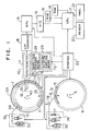
- Fig. 1 schematically shows an analyzing apparatus as an embodiment of this invention.
- Reaction turntable 1 can be rotated on a rotary shaft 40 in clockwise direction.
- a plurality of, e.g., forty, of cuvettes 2 are held on the periphery of reaction turntable 1.
- Sample turntable 4 can be rotated on a rotary shaft 6 in either the forward or backward direction.
- a plurality of sample cups 5, each containing a liquid sample such as, for example, blood serum, are held on the periphery of sample turntable 4.
- the sampling operation is performed by a distributor 74, which has a sampling probe 8 and a probe shifter 78.
- the probe shifter 78 can horizontally shift the sampling probe 8 tipped with a nozzle, from intake position 31 to ejection position 25 and also vertically shift the probe 8 in both intake and ejection positions 31 and 25.
- Distributor 74 also has a microsyringe 7 for taking in the sample, a syringe 9 for supplying the sample and a first vessel 32 for liquid reagent.
- a reagent supplier 76 has a length of pipe 34 extended to the train of cuvettes held by the reaction turntable 1, a syringe 10 for supplying reagent and a second vessel 33 for liquid reagent.
- the supply of reagent for the cuvettes in the reaction turntable 1 is performed by reagent supplier 76.
- the number of reagent supplies 76 to be used is equal to the number of the analysis items each of which requires two kinds of reagent for analysis.
- a drive means for driving the reaction turntable 1 is connected through an interface 22 shown in Fig. 1, with a central processing unit (CPU) 17.
- CPU 17 causes motor 44 to stop when the number of detection signals delivered exceeds a predetermined number which is greater than the number of perforations on disc 45, for example, when forty-one detection signals are delivered. In this case, turntable 1 also makes more than one revolution.
- the light measuring apparatus, photometer 70 in Fig. 1 has a lamp 12 as a light source and a spectrometer 11. Photometer 70 is shown in greater detail in Fig. 2.
- a light beam 13 travelling from light source 12 to spectrometer 11 traverses the path along which the train of cuvettes is conveyed.
- the beam guided into the spectrometer 11 is broken down into different wavelength components by means of a concave grating 58 and the respective components are detected by semiconductor photodetectors array 59 arranged in accordance with the wavelengths to be detected.
- Each of cuvette 2 supported on the turntable 1 and conveyed along a circular path is made to traverse the beam 13 in the photometer during its circular movement.
- the beam path is so positioned that when turntable 1 is stationary, the beam 13 passes through the center of the cuvette 2 which, for example, may be the thirtieth cuvette counted clockwise from ejection position 25.
- the respective photodetectors 59 are connected with corresponding logarithmic amplifiers 15, each of which is connected with two multiplexers 14. Each of the two multiplexers 14 extracts a photo-signal corresponding to a single wavelength. Two of the signals corresponding to the two wavelengths extracted by the two multiplexers are respectively digitalized by an A/D converter 16 and the digital signals are received by the CPU 17.
- a waste liquid drainage pipe 26 and a cleaning solution supply pipe 27 are provided between the sample ejection position and the position of intersection between the light beam 13 and the path of the train cuvettes.
- a cleaning apparatus 72 has a waste liquid drainage means 28 to which drainage pipe 26 is connected and a cleaning solution supplying means 29 to which supply pipe 27 is linked. The waste liquid drainage pipe 26 and cleaning solution supply pipe 27 are shifted down into the cuvettes located at a predetermined positions when turntable 1 is stopped.
- CPU 17 in Fig. 1 is connected through a bus line with the interface 22, A/D converter 16, a read-only memory (or ROM) 18, a random-access memory (or RAM) 19, a manipulation panel 21 and a printer 20.
- the tip of the sampling probe 8 is immersed in the liquid in the sample cup 5 so that a quantity of serum is sucked up and held in the probe 8.
- the probe 8 is then shifted to ejection position 25 and the serum held in the probe 8 is ejected into the cuvette 2 resting at the ejection position 25 while the syringe 9 ejects the specified quantity of the first reaction reagent into the same cuvette.
- a first reagent which is liquid containing enzyme-labeled antiCEA antibody, is accommodated in first reagent vessel 32. Immune reaction is started when the sample containing CEA and the first reagent are ejected into the reaction container located at ejection position 25, by which immune complex starts to be formed on the inner wall surface of reaction container.
- the reaction table 1 After the completion of the above sampling operation, the reaction table 1 starts rotating clockwise and rotates through 369 degrees which corresponds to the angle through which 41 cuvettes, that is, the cuvettes whose number is greater by one than that of all the cuvettes held on the turntable 1, pass through the ejection position 25.
- the cuvette 2 containing the apportioned sample and the first reaction reagent is located at the position in advance by one pitch, i.e., 9 degrees, clockwise of the ejection position 25.
- the spectrometer 11 performs absorbance measurement.
- the output of spectrometer 11 is sent through the logarithmic amplifier 15 to the multiplexer 14, which selects the signal having a desired wavelength.
- the output of multiplexer 14 is sent through the A/D converter 16 to the CPU 17 for storage in the RAM 19.
- the above series of operation is repeated every thirty seconds, provided that a cycle consisting of the time for which turntable 1 is moving and the time for which it is stationary, is set equal to 30 sec. As the cycles advance, a particular sample advances, pitch by pitch, clockwise.
- a tube 34 for adding the second reagent to the sample is located at the fifteenth cuvette counted clockwise from ejection position 25. Accordingly, any particular sample initially resting at the ejection position 25 and undergoing the first reaction there, will receive the second reagent to initiate the second reaction in the fifteenth cycle.
- the preceding operations are effected through the control of the respective mechanisms by the CPU 17 via the interface 22 in accordance with the program stored in ROM 18.
- the operation panel 21 is used to supply measurement conditions and to start and stop measurement.
- the results of the measurement of analysis items are calculated using data obtained after the second reaction has been started, the obtained results being printed out by a printer 20.
- the path in which the train of reaction containers 2 is conveyed consists of a container rotating area in which the reaction containers are rotated on their own axes and a container non-rotating area in which the rotational force is not transmitted to the reaction containers.
- the container rotating area 101 extends over more than half of the total number of the reaction containers on the reaction turntable 1.
- An area other than the container rotating area represents the non-rotating area.
- a curved friction flange 120 is fixedly provided in the container rotating area 101, as shown in Fig. 2.
- Fig. 2 is a plan view, with part broken away, of the vicinity of the reaction turntable 1 of the apparatus of Fig. 1. Note that the reaction containers 2 are shown in Fig. 2 in a number less than that shown in Fig. 1 in order to simplify the explanation.
- Annular bearings 171 are provided in the 40 holes formed in the reaction turntable 1.
- the friction produced between each of the bearings 171 and the reaction container is low.
- the reaction turntable 1 has an upper plate 1a and a lower plate 1b.
- the inner diameter of each of the bearings 171 provided in the upper plate 1a is made substantially equal to the outer diameter of the reaction container 2.
- the upper plate 1b has a plurality of concave portions 52 formed at positions corresponding to the holes formed in the upper plate 1a.
- the spherical bottom portions of the containers 2 are received by the concave portion 52. In this way, a shift of the containers 2 is prevented and the containers can be rotated on their own axes in the concave portion 52 when a relatively strong force is exerted on the outer walls of the containers 2.
- the train of reaction containers is alternately moved in a conveyance state and stopped in a stationary state by the pulse motor 44 mounted on a base 50.
- the friction flange 120 made of silicone rubber is disposed around the train of reaction containers. The inner peripheral surface of the friction flange 120 makes contact with the outer walls of all the reaction containers located within the container rotating area 101.
- a strip of plastic 115 is fixed on part of the outer surface of each of the reaction containers 2 made of glass, as shown in Fig. 4.
- This strip of plastic 115 is formed with a gear like shaped portion over a surface thereof so as to allow the container conveying force to be surely transmitted to the reaction container as the rotational force thereof through the friction flange 120.
- the reaction container 2 is made of a plastic, the strip 115 is formed integrally with the reaction container 2.
- the reaction container 2 also has a plurality of vane-like shaped fins 116 formed on the inner surface of the bottom portion thereof. These fins 116 allow the liquid contained in the reaction container to be efficiently stirred as the reaction container is rotated on its own axis.
- the beam of light 13 passes through the reaction container set in the analyzing apparatus at a position below the strip of plastic 115.
- the inner peripheral surface of the friction flange 120 is preferably formed with a gear like portion over a surface thereof so that the portion can be engaged with the gear like shaped portion formed on the strip 115 of the container 2.
- the friction flange may be made from a material having a high coefficient of friction and the flange may be made of a generally employed plastic.
- the rotation of the reaction turntable 1 causes the reaction containers located within the rotating area 101 to be rotated on their own axes in the direction indicated by an arrow 60.
- a disk 45 mounted on the lower portion of the rotary shaft 40 of the reaction turntable 1 is a spur gear.
- the driving force of the stepping motor 44 is transmitted to the disk 45 through a transmitting gear 56.
- the friction flange 120 is fixed to a vertical portion 51 of the base 50 by a fixture 109.
- the reaction containers 2 on the reaction turntable 1 are not rotated in the bearings 171.
- the reaction containers 2 on the reaction turntable 1 are kept in contact with the friction flange 120 between a rotation starting position 117 and a rotation ending position 118 while the reaction turntable 1 is moved clockwise, they keep rotating on their own axes in this area. After they have passed the rotation ending position 118, they no longer contact with the friction flange 120 and, therefore, the rotation of the containers is stopped.
- the liquid contained in the reaction containers keeps rotating for a while by means of inertia.
- the rotation of the liquid contained in the reaction container 2 must be substantially stopped during the measurement of the liquid by the light beam 13.
- a stable measured value can be obtained only when the motion of the liquid in the container 1 completely stops while the container 2 is being conveyed from the rotation ending position 118 to the light measured position 119 in Fig. 1.
- the light measuring operation is started only when the rotation of the liquid in the reaction container is substantially stopped.
- the time between the ending of the rotation of the reaction container and the starting of light measurement is set at 4 to 5 seconds, if the employed serum sample is a normal reaction liquid. In the case when the viscosity of the reaction liquid is high, this time can be shortened, because the inertia readily stops the motion of the reaction liquid. However, at least 2 seconds are required before the light measurement is started.
- the reaction liquid which continues rotating due to inertia after the rotation of the container has been stopped, stops within 7 seconds.
- the distance or the angle between the rotation ending position 118 and the light measured position 119 in Fig. 2 is so set that it ensures 7 seconds between the starting of the light measurement and the ending of the rotation of the container on its own axis. This time interval is set at within 10 seconds at a maximum.
- Fig. 5 shows the results of the experiments which were conducted to show the effect of stirring in the analysis performed by using the analyzing apparatus shown in Fig. 1.
- the CEA is microprotein contained in blood, and was measured by enzyme immunoassay method (hereinafter referred to as EIA method).
- CEA complex antiCEA antibody - CEA - enzyme-labeled antibody
- the rate of antigen-antibody reaction itself is very high.
- the concentration of CEA is blood is extremely low, for example, it is contained in an amount which is several nanomol to several tens nanomol per milliliter, if the reaction container containing the specimen and the reagent is left stationary so that the CEA complex is formed only by thermodynamic diffusion, reaction occurs at a very low rate.
- the CEA in the solution is caused to collide forcibly against the wall surface of the reaction container by stirring the solution so as to raise the probability of reaction, the rate of reaction rises.
- the antigen-antibody reactions were performed under two different conditions, i.e., in one case, the reaction container was left stationary while the antigen-antibody reaction was occurring, and in the other case, the solution in the container was stirred in accordance with the present invention. In both cases, the reaction efficiency was obtained at various reaction times. After the antigen-antibody reaction, the contents of the container were treated in the same way in both cases. More specifically, free enzyme-labeled antibody which was not bonded to the antigen was first removed by cleansing.
- stroma and a coloring agent were ejected into the reaction container which was cleansed and on which the immune complex remained so as to color the stroma and the coloring agent by the enzyme contained in the enzyme-labeled antibody bonded to the antigen, and the degree of coloring was measured using the spectrophotometer.
- Fig. 5 in the stationary state B, it took about 4 hours to complete the reaction, whereas in the stirring state A which conforms to the present invention, the reaction was completed in about 2 hours, and the rate of reaction doubled.
- a plurality of reaction containers held on a rack are conveyed in a straight line along a conveying path.
- the transparent reaction containers are respectively held in a plurality of holes formed in the rack 80. Since the friction between each of the reaction containers and the rack is small, when the container makes contact with a contact member, the motion of the rack which conveys the reaction containers is transmitted to the container and the container therefore rotates on its own axis.
- the rack 80 is supplied from a rack supplying portion 61 to a sample adding position 62 located on a conveying path 69, where blood serum sample is ejected into each of reaction containers 82 held on the rack 80 while the rack 80 is at stop.
- the rack 80 is then conveyed to a reagent adding position 63, where reagent solution corresponding to the analysis item is ejected into each of the reaction containers 82 while the rack 80 is at stop.
- the rack 80 is continuously conveyed on the conveying path 69 through a container rotating area 64 and a non-rotation area 65.
- the reaction liquid contained in each of the reaction containers 82 traverses the light beam 13, and light measurement of the reaction liquid is performed.
- the rack 80 is then retrieved into a rack retrieving portion 67.
- reaction containers held on the rack 80 pass through the container rotating area 64, they are rotated on the rack 80 on their own axes so as to allow the liquids contained in the reaction containers to be stirred.
- a pair of contact plates 84 and 85 are fixedly provided along the conveying path 69 in the container rotating area 64.
- the contact plates 84 and 85 respectively consist of a plurality of contact ends 86, 87, 88, 91, 92, 93 which protrude so that they make contact with the outer walls of the containers.
- the reaction containers on the rack 80 are successively brought into contact with the large number of contact ends.
- the motion of the rack is transmitted to the reaction containers on the rack 80 by means of friction, and the reaction containers are thereby rotated on their own axes. Since the contact ends 86 to 88 of the contact plate 84 and the contact ends 91 to 93 of the contact plate 85 are alternately located on the different sides of the conveying path, the reaction containers are alternately rotated in opposite directions, i.e., clockwise and counterclockwise. In the state shown in Fig.
- reaction containers 82a and 82b which are in contact with the contact end 86 are rotating counterclockwise
- reaction containers 82c and 82d which are in contact with the contact end 92 are rotating clockwise
- a reaction container 82e which is in contact with the contact end 87 is rotating counterclockwise. In this way, the liquid contained in each of the reaction containers can be stirred efficiently.
Description
- The present invention relates to an analyzing apparatus for measuring liquid samples and an analyzing method thereof. In particular, the present invention pertains to an analyzing apparatus which enables liquid samples accommodated in containers to be stirred by moving the containers, and an analyzing method thereof.
- When the trace components of a body fluid sample is measured utilizing the immune reaction, the possibility of the mutual contamination (carry over) of specimens must be reduced as much as possible. Also, in order to sequentially and stably cause the immunoreaction place in a reaction container which contains a liquid sample and a reagent, it is necessary for the mixture solution of the liquid sample and the reagent to be stirred. Generally, the liquid contained in the reaction container is stirred by a stirring rod inserted into the reaction container. However, in this method, the possibility of the mutual contamination of the specimens is high.
- Accordingly, some attempts have been made to stir the liquid contained in the reaction container without use of a stirring rod. For example, Japanese Patent Laid-Open No. 57-42325 (which corresponds to British Patent No. 2081118) discloses a stirring method in which a total of a large number of reaction containers arranged on a turntable are simultaneously rotated by rotating an annular rotary disk provided inside of the train of reaction containers in opposed two directions with separate driving sources.
- An object of the present invention is to provide an analyzing apparatus which is capable of efficiently analyzing test solutions without the need for spending time to be required only for stirring operation, and an analyzing method thereof.
- Another object of the present invention is to provide an analyzing apparatus in which light measurement can be performed on a test solution contained in one of containers while a test solution contained in another container is being stirred, and an analyzing method thereof.
- Another object of the present invention is to provide an analyzing apparatus which enables the test solutions to be stirred in some of containers during the conveyance of a train of containers, and an analyzing method thereof.
- Another object of the present invention is to provide an analyzing apparatus in which the conveyance of a train of containers and stirring of the test solutions in the containers can be performed by using one driving device, and an analyzing method thereof.
- In the present invention, a train of containers is provided on a movable holder, and the train is conveyed such that it passes through a container rotating area and a container non-rotating area. The motion of the movable holder driven by a driving source is transmitted to the containers located in the container rotating area as a rotational force on the containers on their own axes. In the container non-rotating area, an light beam of a photometer is formed so that the light measurement can be performed to measure the test solutions in the containers which arrived at the non-rotating area. The movable holder continuously moves the distance which is a plurality of times the distance between the adjacent containers, and both of the stirring of the test solutions and the light measurement of the test solutions are performed during this movement. Precisely, each of the test solutions is measured by means of the photometer in a range from 2 to 10 seconds after it has stopped rotating on its own axis.
-
- Fig. 1 is a schematic view of a blood sample analyzing apparatus, showing a first embodiment of the present invention;
- Fig. 2 schematically shows the vicinity of a reaction table of the structure of Fig. 1;
- Fig. 3 is a section view taken along the line III - III of Fig. 2;
- Fig. 4 shows a reaction container employed in the embodiment shown in Fig. 1;
- Fig. 5 is a graph showing the experiment results obtained on the efficiency of stirring operation;
- Fig. 6 is a schematic view of an analyzing apparatus, showing a second embodiment of the present invention; and
- Fig. 7 shows how the containers located in a container-rotating area rotate on their own axes in the embodiment shown in Fig. 6.
- In a preferred form of the present invention, an analyzing apparatus includes a motion transmitting means that can be made into contact with the outer wall surfaces of reaction containers arranged on a reaction turntable. The motion transmitting means has a fixed contact member, and transmits the motion of the train of containers which are conveyed by the turntable as the rotational force of the reaction containers on the turntable on their own axes. As the reaction container rotates on its own axis, the liquid contained in that reaction container is stirred.
- Note that the outer wall surface of the reaction container includes a surface of the wall that forms the reaction container, a surface of a strip provided on the outside of the reaction container to prevent slide of the reaction container, and a surface of a container covering member which is formed integrally with the reaction container.
- In one of the embodiments of the present invention, a turntable has holes thereon. Each of the holes is formed in the circumferential directions at fixed intervals. A cylindrical reaction container is held by the inner periphery of each of the holes. A bearing is provided in each of the holes so that the reaction container placed in the bearing can be smoothly rotated on its own axis. A friction member is provided concentrically with respect to the turntable at a position where it makes contact with the side of the reaction container. Coefficient of friction between the friction member and the containers is set to an appropriate value. The reaction containers are rotated on their own axes by means of friction caused when the turntable is rotated without the need for a special reaction container rotating device.
- Further, rotation of the reaction containers on their own axes can be stopped at a particular location while the turntable is rotating by providing notches in the fixed friction member disposed in the circumferential direction. The friction member, which is called "friction flange", or the surface thereof may be made of a relatively soft material having a high coefficient skin friction. For example, silicone rubber is suitable for the material. The friction member itself is generally made of a synthetic resin. In that case, if a sufficient amount of frictional force is not produced between the reaction containers and the friction member, (gear like shaped-) irregularities are formed on the surface of the friction member so that they are engaged with the irregularities formed on the reaction containers so as to allow a rotational force to be efficiently transmitted. The friction produced between the through-hole and each of the reaction containers held by the corresponding through-hole in the turntable is low. This prevents the reaction container from being moved while the turntable is being stopped. This also prevents the container from being shafted. The through-holes in the turntable are adequately made of a synthetic resin having less coefficient of skin friction than that of silicon rubber, such as a polyethylene resin, a vinyl chloride resin or an ABS resin.
- In the embodiment shown in Fig. 1, which is described later, a rotating state in which the turntable conveys the train of reaction containers and a stationary state in which the turntable does not convey the train of reaction containers are alternately repeated. As the conveying operation is stopped, the rotation of the reaction containers on their own axes stops due to the friction between the through-holes in the turntable and the reaction containers. However, after the rotation of the reaction containers has been stopped, the inertia causes the liquid in the reaction containers to keep rotating for a while. If a friction member made of silicon rubber is employed and if the turntable is stopped after it has made one revolution, the liquid in the reaction containers continues rotating for about 4 seconds after the rotation of the cylindrical reaction containers made of glass has been stopped. This time the liquid in the reaction containers keeps rotating varies, depending on the shape of the reaction containers or the properties of the liquid. While the liquid is rotating alone, the sample and the reagent in the liquid can be stirred and mixed more uniformly.
- During the rotation of the turntable, the reaction containers located on the turntable make contact with the friction member and are thereby rotated on their own axes. In other words, the two different objects, i.e., the positioning of the turntable and the rotation of the reaction containers, can be achieved by the provision of a driving device for the turntable. Further, the friction member, which is disposed in the circumferential direction in such a manner that it makes contact with the reaction containers, does not make contact with the reaction containers at a point where the rotation of the reaction containers is not required, such as at a point where light measurement is performed or at a point where the reaction containers are supplied to or removed from the turntable. The friction member may be brought into contact with the inner side or the outer side of the train of reaction containers arranged in a circular conveying path, or both of the inner and outer sides of the reaction containers.
- Fig. 1 schematically shows an analyzing apparatus as an embodiment of this invention.
Reaction turntable 1 can be rotated on arotary shaft 40 in clockwise direction. A plurality of, e.g., forty, ofcuvettes 2 are held on the periphery ofreaction turntable 1.Sample turntable 4 can be rotated on a rotary shaft 6 in either the forward or backward direction. A plurality of sample cups 5, each containing a liquid sample such as, for example, blood serum, are held on the periphery ofsample turntable 4. - The sampling operation is performed by a
distributor 74, which has a sampling probe 8 and aprobe shifter 78. Theprobe shifter 78 can horizontally shift the sampling probe 8 tipped with a nozzle, fromintake position 31 toejection position 25 and also vertically shift the probe 8 in both intake and ejection positions 31 and 25.Distributor 74 also has a microsyringe 7 for taking in the sample, asyringe 9 for supplying the sample and afirst vessel 32 for liquid reagent. - A
reagent supplier 76 has a length ofpipe 34 extended to the train of cuvettes held by thereaction turntable 1, asyringe 10 for supplying reagent and asecond vessel 33 for liquid reagent. The supply of reagent for the cuvettes in thereaction turntable 1 is performed byreagent supplier 76. The number of reagent supplies 76 to be used is equal to the number of the analysis items each of which requires two kinds of reagent for analysis. - A drive means for driving the
reaction turntable 1 is connected through aninterface 22 shown in Fig. 1, with a central processing unit (CPU) 17.CPU 17 causes motor 44 to stop when the number of detection signals delivered exceeds a predetermined number which is greater than the number of perforations ondisc 45, for example, when forty-one detection signals are delivered. In this case,turntable 1 also makes more than one revolution. - The light measuring apparatus,
photometer 70 in Fig. 1, has alamp 12 as a light source and a spectrometer 11.Photometer 70 is shown in greater detail in Fig. 2. Alight beam 13 travelling fromlight source 12 to spectrometer 11 traverses the path along which the train of cuvettes is conveyed. The beam guided into the spectrometer 11 is broken down into different wavelength components by means of aconcave grating 58 and the respective components are detected bysemiconductor photodetectors array 59 arranged in accordance with the wavelengths to be detected. Each ofcuvette 2 supported on theturntable 1 and conveyed along a circular path is made to traverse thebeam 13 in the photometer during its circular movement. Sincebeam 13 is made to pass through thecuvette 2 and the liquid contained therein, the total absorption of light, that is, the absorption by thecuvette 2 plus the absorption by the liquid therein, can be detected. The beam path is so positioned that whenturntable 1 is stationary, thebeam 13 passes through the center of thecuvette 2 which, for example, may be the thirtieth cuvette counted clockwise fromejection position 25. Therespective photodetectors 59 are connected with correspondinglogarithmic amplifiers 15, each of which is connected with twomultiplexers 14. Each of the twomultiplexers 14 extracts a photo-signal corresponding to a single wavelength. Two of the signals corresponding to the two wavelengths extracted by the two multiplexers are respectively digitalized by an A/D converter 16 and the digital signals are received by theCPU 17. - A waste
liquid drainage pipe 26 and a cleaningsolution supply pipe 27 are provided between the sample ejection position and the position of intersection between thelight beam 13 and the path of the train cuvettes. Acleaning apparatus 72 has a waste liquid drainage means 28 to whichdrainage pipe 26 is connected and a cleaning solution supplying means 29 to whichsupply pipe 27 is linked. The wasteliquid drainage pipe 26 and cleaningsolution supply pipe 27 are shifted down into the cuvettes located at a predetermined positions whenturntable 1 is stopped.CPU 17 in Fig. 1 is connected through a bus line with theinterface 22, A/D converter 16, a read-only memory (or ROM) 18, a random-access memory (or RAM) 19, amanipulation panel 21 and aprinter 20. - When the sampling cup 5 containing a serum sample is sent to
sampling position 31 on thesample turntable 4, the tip of the sampling probe 8 is immersed in the liquid in the sample cup 5 so that a quantity of serum is sucked up and held in the probe 8. The probe 8 is then shifted toejection position 25 and the serum held in the probe 8 is ejected into thecuvette 2 resting at theejection position 25 while thesyringe 9 ejects the specified quantity of the first reaction reagent into the same cuvette. - The inner wall surfaces of cuvettes or
reaction containers 2 are coated with a special antibody required for antigen-antibody reaction, for example, antiCEA antibody. A first reagent, which is liquid containing enzyme-labeled antiCEA antibody, is accommodated infirst reagent vessel 32. Immune reaction is started when the sample containing CEA and the first reagent are ejected into the reaction container located atejection position 25, by which immune complex starts to be formed on the inner wall surface of reaction container. - After the completion of the above sampling operation, the reaction table 1 starts rotating clockwise and rotates through 369 degrees which corresponds to the angle through which 41 cuvettes, that is, the cuvettes whose number is greater by one than that of all the cuvettes held on the
turntable 1, pass through theejection position 25. - After the above rotational operation, the
cuvette 2 containing the apportioned sample and the first reaction reagent is located at the position in advance by one pitch, i.e., 9 degrees, clockwise of theejection position 25. During one revolution ofturntable 1, all thecuvettes 2 onturntable 1traverse light beam 13. Accordingly, when eachcuvette 2 crosses thebeam 13, the spectrometer 11 performs absorbance measurement. The output of spectrometer 11 is sent through thelogarithmic amplifier 15 to themultiplexer 14, which selects the signal having a desired wavelength. The output ofmultiplexer 14 is sent through the A/D converter 16 to theCPU 17 for storage in theRAM 19. The above series of operation is repeated every thirty seconds, provided that a cycle consisting of the time for whichturntable 1 is moving and the time for which it is stationary, is set equal to 30 sec. As the cycles advance, a particular sample advances, pitch by pitch, clockwise. - A
tube 34 for adding the second reagent to the sample is located at the fifteenth cuvette counted clockwise fromejection position 25. Accordingly, any particular sample initially resting at theejection position 25 and undergoing the first reaction there, will receive the second reagent to initiate the second reaction in the fifteenth cycle. - The preceding operations are effected through the control of the respective mechanisms by the
CPU 17 via theinterface 22 in accordance with the program stored inROM 18. Theoperation panel 21 is used to supply measurement conditions and to start and stop measurement. The results of the measurement of analysis items are calculated using data obtained after the second reaction has been started, the obtained results being printed out by aprinter 20. - In the embodiment shown in Fig. 1, the path in which the train of
reaction containers 2 is conveyed consists of a container rotating area in which the reaction containers are rotated on their own axes and a container non-rotating area in which the rotational force is not transmitted to the reaction containers. Thecontainer rotating area 101 extends over more than half of the total number of the reaction containers on thereaction turntable 1. An area other than the container rotating area represents the non-rotating area. Acurved friction flange 120 is fixedly provided in thecontainer rotating area 101, as shown in Fig. 2. - Fig. 2 is a plan view, with part broken away, of the vicinity of the
reaction turntable 1 of the apparatus of Fig. 1. Note that thereaction containers 2 are shown in Fig. 2 in a number less than that shown in Fig. 1 in order to simplify the explanation. -
Annular bearings 171 are provided in the 40 holes formed in thereaction turntable 1. The friction produced between each of thebearings 171 and the reaction container is low. Thereaction turntable 1 has an upper plate 1a and a lower plate 1b. The inner diameter of each of thebearings 171 provided in the upper plate 1a is made substantially equal to the outer diameter of thereaction container 2. The upper plate 1b has a plurality ofconcave portions 52 formed at positions corresponding to the holes formed in the upper plate 1a. The spherical bottom portions of thecontainers 2 are received by theconcave portion 52. In this way, a shift of thecontainers 2 is prevented and the containers can be rotated on their own axes in theconcave portion 52 when a relatively strong force is exerted on the outer walls of thecontainers 2. - The train of reaction containers is alternately moved in a conveyance state and stopped in a stationary state by the
pulse motor 44 mounted on abase 50. Thefriction flange 120 made of silicone rubber is disposed around the train of reaction containers. The inner peripheral surface of thefriction flange 120 makes contact with the outer walls of all the reaction containers located within thecontainer rotating area 101. - A strip of plastic 115 is fixed on part of the outer surface of each of the
reaction containers 2 made of glass, as shown in Fig. 4. This strip of plastic 115 is formed with a gear like shaped portion over a surface thereof so as to allow the container conveying force to be surely transmitted to the reaction container as the rotational force thereof through thefriction flange 120. If thereaction container 2 is made of a plastic, the strip 115 is formed integrally with thereaction container 2. Thereaction container 2 also has a plurality of vane-like shapedfins 116 formed on the inner surface of the bottom portion thereof. Thesefins 116 allow the liquid contained in the reaction container to be efficiently stirred as the reaction container is rotated on its own axis. The beam of light 13 passes through the reaction container set in the analyzing apparatus at a position below the strip of plastic 115. - It is preferably for the inner peripheral surface of the
friction flange 120 to be formed with a gear like portion over a surface thereof so that the portion can be engaged with the gear like shaped portion formed on the strip 115 of thecontainer 2. In that case, it is not required that the friction flange may be made from a material having a high coefficient of friction and the flange may be made of a generally employed plastic. - Since the friction produced between the
friction flange 120 and thereaction container 2 is higher than the friction caused between the reaction container and thebearing 171, the rotation of thereaction turntable 1 causes the reaction containers located within the rotatingarea 101 to be rotated on their own axes in the direction indicated by anarrow 60. - A
disk 45 mounted on the lower portion of therotary shaft 40 of thereaction turntable 1 is a spur gear. The driving force of the steppingmotor 44 is transmitted to thedisk 45 through a transmittinggear 56. Thefriction flange 120 is fixed to avertical portion 51 of the base 50 by a fixture 109. - In the non-rotating area where no
friction flange 120 is disposed, thereaction containers 2 on thereaction turntable 1 are not rotated in thebearings 171. On the other hand, since thereaction containers 2 on thereaction turntable 1 are kept in contact with thefriction flange 120 between arotation starting position 117 and arotation ending position 118 while thereaction turntable 1 is moved clockwise, they keep rotating on their own axes in this area. After they have passed therotation ending position 118, they no longer contact with thefriction flange 120 and, therefore, the rotation of the containers is stopped. However, the liquid contained in the reaction containers keeps rotating for a while by means of inertia. - The rotation of the liquid contained in the
reaction container 2 must be substantially stopped during the measurement of the liquid by thelight beam 13. A stable measured value can be obtained only when the motion of the liquid in thecontainer 1 completely stops while thecontainer 2 is being conveyed from therotation ending position 118 to the light measuredposition 119 in Fig. 1. - After the rotation of the reaction container has stopped, the light measuring operation is started only when the rotation of the liquid in the reaction container is substantially stopped. On the other hand, it is essential to process as many specimens as possible within a predetermined time. The time between the ending of the rotation of the reaction container and the starting of light measurement is set at 4 to 5 seconds, if the employed serum sample is a normal reaction liquid. In the case when the viscosity of the reaction liquid is high, this time can be shortened, because the inertia readily stops the motion of the reaction liquid. However, at least 2 seconds are required before the light measurement is started. Even if the rotational speed of the reaction container is high, for example, even if it is 1000 rpm, the reaction liquid, which continues rotating due to inertia after the rotation of the container has been stopped, stops within 7 seconds. In consequence, the distance or the angle between the
rotation ending position 118 and the light measuredposition 119 in Fig. 2 is so set that it ensures 7 seconds between the starting of the light measurement and the ending of the rotation of the container on its own axis. This time interval is set at within 10 seconds at a maximum. - Fig. 5 shows the results of the experiments which were conducted to show the effect of stirring in the analysis performed by using the analyzing apparatus shown in Fig. 1. In the experiments, the effect of stirring to the rate of antigen-antibody reaction in the measurement of cartinoembryonic antigen (hereinafter referred to as CEA), was examined. The CEA is microprotein contained in blood, and was measured by enzyme immunoassay method (hereinafter referred to as EIA method). When a specimen containing CEA and enzyme labeled-antiCEA antibody (hereinafter referred to as enzyme labeled-antibody) are ejected into a reaction container the inner wall of which is coated with antiCEA antibody, CEA complex (antiCEA antibody - CEA - enzyme-labeled antibody) is formed on the inner wall of the reaction container.
- The rate of antigen-antibody reaction itself is very high. However, since the concentration of CEA is blood is extremely low, for example, it is contained in an amount which is several nanomol to several tens nanomol per milliliter, if the reaction container containing the specimen and the reagent is left stationary so that the CEA complex is formed only by thermodynamic diffusion, reaction occurs at a very low rate. However, if the CEA in the solution is caused to collide forcibly against the wall surface of the reaction container by stirring the solution so as to raise the probability of reaction, the rate of reaction rises.
- In the experiments, the antigen-antibody reactions were performed under two different conditions, i.e., in one case, the reaction container was left stationary while the antigen-antibody reaction was occurring, and in the other case, the solution in the container was stirred in accordance with the present invention. In both cases, the reaction efficiency was obtained at various reaction times. After the antigen-antibody reaction, the contents of the container were treated in the same way in both cases. More specifically, free enzyme-labeled antibody which was not bonded to the antigen was first removed by cleansing. Thereafter, stroma and a coloring agent were ejected into the reaction container which was cleansed and on which the immune complex remained so as to color the stroma and the coloring agent by the enzyme contained in the enzyme-labeled antibody bonded to the antigen, and the degree of coloring was measured using the spectrophotometer. As is clear from Fig. 5, in the stationary state B, it took about 4 hours to complete the reaction, whereas in the stirring state A which conforms to the present invention, the reaction was completed in about 2 hours, and the rate of reaction doubled.
- Another embodiment of the present invention will be described below with reference to Figs. 6 and 7. In this automatic blood analyzing apparatus, a plurality of reaction containers held on a rack are conveyed in a straight line along a conveying path. The transparent reaction containers are respectively held in a plurality of holes formed in the
rack 80. Since the friction between each of the reaction containers and the rack is small, when the container makes contact with a contact member, the motion of the rack which conveys the reaction containers is transmitted to the container and the container therefore rotates on its own axis. - The
rack 80 is supplied from arack supplying portion 61 to a sample adding position 62 located on a conveying path 69, where blood serum sample is ejected into each ofreaction containers 82 held on therack 80 while therack 80 is at stop. Therack 80 is then conveyed to a reagent adding position 63, where reagent solution corresponding to the analysis item is ejected into each of thereaction containers 82 while therack 80 is at stop. Subsequently, therack 80 is continuously conveyed on the conveying path 69 through acontainer rotating area 64 and anon-rotation area 65. During the conveyance of thisrack 80, the reaction liquid contained in each of thereaction containers 82 traverses thelight beam 13, and light measurement of the reaction liquid is performed. Therack 80 is then retrieved into arack retrieving portion 67. - While the reaction containers held on the
rack 80 pass through thecontainer rotating area 64, they are rotated on therack 80 on their own axes so as to allow the liquids contained in the reaction containers to be stirred. A pair ofcontact plates container rotating area 64. Thecontact plates - In the
container rotating area 64, when therack 80 is conveyed by a driving device (not shown) in the direction indicated by an arrow 99, as shown in Fig. 7, the reaction containers on therack 80 are successively brought into contact with the large number of contact ends. At this time, the motion of the rack is transmitted to the reaction containers on therack 80 by means of friction, and the reaction containers are thereby rotated on their own axes. Since the contact ends 86 to 88 of thecontact plate 84 and the contact ends 91 to 93 of thecontact plate 85 are alternately located on the different sides of the conveying path, the reaction containers are alternately rotated in opposite directions, i.e., clockwise and counterclockwise. In the state shown in Fig. 7,reaction containers contact end 86 are rotating counterclockwise,reaction containers contact end 87 is rotating counterclockwise. In this way, the liquid contained in each of the reaction containers can be stirred efficiently. - Once the train of reaction containers enters the
non-rotating area 65, the rotation of the reaction containers on their own axis stops. The rotational motion of the reaction liquid contained in the reaction containers caused by the inertia also stops before the reaction container reaches thelight beam 13.
Claims (14)
- An analyzing apparatus, comprising:
a movable holder (1, 80) on which a plurality of containers (2) for accommodating a liquid to be stirred are arranged each of said containers (2) having an axis of rotation characterized by;
drive means (44) for driving said movable holder (1, 80) so that a train of said containers (2, 82) passes through a container rotating area (101, 64) where said containers are rotated on their own yes and a non-rotating area where said containers (2, 82) are not rotated;
transmitting means (120, 84, 85) for transmitting the motion of said movable holder (1, 80) as a rotational force on said containers (2) in said train of containers (2) on their own axes in said container rotating area (101, 64); and
a photometer (70) for irradiating said containers (2, 82) in said train of containers with light beam in said non-rotating area. - An analyzing apparatus according to claim 1, wherein said containers (2, 82) are made of a transparent material, and the outer periphery of each of said containers (2, 82) has irregularities (115) which are brought into contact with said transmitting means (120, 84, 85).
- An analyzing apparatus according to claim 1 or 2, wherein said drive means (44) drives said moveable holder (1, 80) so that said train of containers (2) are moved intermittently.
- An analyzing apparatus according to claim 1, 2 or 3, wherein said transmitting means (120, 84, 85) includes a contact member disposed in such a manner that it can make contact with the outer wall of said container (2, 82).
- An analyzing apparatus according to claim 4, wherein said contact member is fixedly provided.
- An analyzing apparatus according to claim 4, wherein said contact member is brought into contact with a plurality of containers in said train of containers (2, 82) simultaneously.
- An analyzing apparatus according to claim 4, wherein said contact member has a plurality of ends that make contact with the containers in said train of containers (2, 82) , and wherein said contact ends are alternately disposed on two sides of said train of containers (2, 82).
- An analyzing apparatus according to any of the preceding claims, further comprising means for controlling said photometer for beginning an irradiating of said containers in a range of 2 to 10 seconds after it has stopped rotating on its own axis.
- An analyzing apparatus according to any of the preceding claims, wherein said containers have vein shaped fins on an interior portion thereof for stirring.
- An analyzing apparatus according to any of the preceding claims, wherein said drive means drives said plurality of containers in only one direction.
- An analyzing apparatus according to claim 10, wherein said drive means is a pulse motor that intermittently drives said holding means.
- An analyzing apparatus according to any of the preceding claims, wherein said holding means comprises upper and lower discs, said upper disc having through holes with bearings for receiving said containers therein, and said bottom disc having concave portions aligned with said through holes for supporting a bottom portion of said containers.
- An analyzing method, containing the steps of:
holding on a movable holder (1, 80) a plurality of containers (2) each having an axis of rotation;
alternately exerting a train of containers (2, 82) on a conveyed state and a stopped state characterized by;
making said containers in said train of containers rotate on their own axes by transmitting the motion of said movable holder as a rotational force on said containers while said containers pass through a container rotating area during the conveyance of said containers (2, 82),; and
measuring the optical characteristics of the liquid contained in said container in said train of containers by irradiating said container with light beam when said containers pass a light measuring position (119) during the conveyance of said containers, in a container non-rotating area. - An analyzing method according to claim 13, characterized in that a sample and/or a reagent is ejected into a container located at a predetermined position (25) while the conveyance of said train of containers (2, 82) is being stopped.
Applications Claiming Priority (2)
| Application Number | Priority Date | Filing Date | Title |
|---|---|---|---|
| JP35289/88 | 1988-02-19 | ||
| JP3528988 | 1988-02-19 |
Publications (3)
| Publication Number | Publication Date |
|---|---|
| EP0329183A2 EP0329183A2 (en) | 1989-08-23 |
| EP0329183A3 EP0329183A3 (en) | 1990-07-25 |
| EP0329183B1 true EP0329183B1 (en) | 1994-10-26 |
Family
ID=12437615
Family Applications (1)
| Application Number | Title | Priority Date | Filing Date |
|---|---|---|---|
| EP89102808A Expired - Lifetime EP0329183B1 (en) | 1988-02-19 | 1989-02-17 | Analyzing apparatus in which liquid can be stirred and analyzing method thereof |
Country Status (3)
| Country | Link |
|---|---|
| US (1) | US5104807A (en) |
| EP (1) | EP0329183B1 (en) |
| DE (1) | DE68918962T2 (en) |
Cited By (1)
| Publication number | Priority date | Publication date | Assignee | Title |
|---|---|---|---|---|
| US6562298B1 (en) | 1996-09-19 | 2003-05-13 | Abbott Laboratories | Structure for determination of item of interest in a sample |
Families Citing this family (31)
| Publication number | Priority date | Publication date | Assignee | Title |
|---|---|---|---|---|
| US5104807A (en) * | 1988-02-19 | 1992-04-14 | Hitachi, Ltd. | Analyzing apparatus in which liquid can be stirred and analyzing method thereof |
| JP2539512B2 (en) * | 1989-07-17 | 1996-10-02 | 株式会社日立製作所 | Multi-item analyzer and method for operating the analyzer |
| US5183638A (en) * | 1989-12-04 | 1993-02-02 | Kabushiki Kaisha Nittec | Automatic immunity analysis apparatus with magnetic particle separation |
| ATE157459T1 (en) * | 1989-12-22 | 1997-09-15 | Alfa Biotech Spa | DEVICE FOR SELECTIVE STIRRING REACTION COMPONENTS |
| US20060013729A1 (en) * | 1991-02-14 | 2006-01-19 | Glen Carey | Fluid handling apparatus for an automated analyzer |
| US6436349B1 (en) * | 1991-03-04 | 2002-08-20 | Bayer Corporation | Fluid handling apparatus for an automated analyzer |
| US6498037B1 (en) * | 1991-03-04 | 2002-12-24 | Bayer Corporation | Method of handling reagents in a random access protocol |
| US5360597A (en) * | 1993-03-22 | 1994-11-01 | Eastman Kodak Company | Ribbed mechanism for mixing sample by vibration |
| EP0571034A1 (en) * | 1992-05-22 | 1993-11-24 | Johnson & Johnson Clinical Diagnostics, Inc. | Mixing mechanism for analyzers |
| US5466416A (en) * | 1993-05-14 | 1995-11-14 | Ghaed; Ali | Apparatus and methods for carrying out electrochemiluminescence test measurements |
| EP0787990A4 (en) * | 1994-10-19 | 1998-12-23 | Japan Tectron Instr Corp | Automatic analyzer |
| US5744099A (en) * | 1995-09-15 | 1998-04-28 | Cytek Development Inc. | Apparatus for transfer of biological fluids |
| DE19540877C2 (en) * | 1995-11-02 | 1998-02-26 | Byk Sangtec Diagnostica | Modular reagent cartridge |
| US5813759A (en) * | 1996-07-03 | 1998-09-29 | Dade International Inc. | Method and apparatus for vortex mixing using centrifugal force |
| US5795784A (en) | 1996-09-19 | 1998-08-18 | Abbott Laboratories | Method of performing a process for determining an item of interest in a sample |
| US6135940A (en) * | 1996-09-25 | 2000-10-24 | Becton, Dickinson And Company | Centrifugally activated tube rotator mechanism and method for using the same |
| US6152868A (en) * | 1998-03-02 | 2000-11-28 | Becton, Dickinson And Company | Inertial tube indexer |
| US6120429A (en) * | 1998-03-02 | 2000-09-19 | Becton, Dickinson And Company | Method of using inertial tube indexer |
| DE19819447A1 (en) | 1998-04-30 | 1999-11-04 | Roche Diagnostics Gmbh | Device and method for mixing and washing liquids and / or solids |
| US8337753B2 (en) * | 1998-05-01 | 2012-12-25 | Gen-Probe Incorporated | Temperature-controlled incubator having a receptacle mixing mechanism |
| ATE363339T1 (en) | 1998-05-01 | 2007-06-15 | Gen Probe Inc | STIRRING DEVICE FOR THE FLUID CONTENTS OF A CONTAINER |
| DE10053209A1 (en) * | 2000-10-26 | 2002-08-01 | Siemens Ag | Display adapter for comfort telephones |
| US7217391B2 (en) * | 2001-03-16 | 2007-05-15 | Beckman Coulter, Inc. | Rotary incubation station for immunoassay systems |
| EP1384988B1 (en) * | 2002-07-22 | 2007-03-07 | The Automation Partnership (Cambridge) Limited | IR analysis system |
| US8313713B2 (en) * | 2004-06-17 | 2012-11-20 | Ortho-Clinical Diagnostics, Inc. | Stabilizing a cuvette during measurement |
| US7776263B2 (en) * | 2004-10-29 | 2010-08-17 | Abbott Laboratories Inc. | Apparatus for providing homogeneous dispersions |
| US7932081B2 (en) * | 2005-03-10 | 2011-04-26 | Gen-Probe Incorporated | Signal measuring system for conducting real-time amplification assays |
| US9046507B2 (en) | 2010-07-29 | 2015-06-02 | Gen-Probe Incorporated | Method, system and apparatus for incorporating capacitive proximity sensing in an automated fluid transfer procedure |
| CN103403533B (en) | 2011-02-24 | 2017-02-15 | 简.探针公司 | Systems and methods for distinguishing optical signals of different modulation frequencies in an optical signal detector |
| US9366617B1 (en) * | 2015-07-10 | 2016-06-14 | David E. Doggett | Self-stirring container |
| US9677988B1 (en) | 2015-07-10 | 2017-06-13 | David E. Doggett | Integrating radiation collection and detection apparatus |
Citations (1)
| Publication number | Priority date | Publication date | Assignee | Title |
|---|---|---|---|---|
| US5104807A (en) * | 1988-02-19 | 1992-04-14 | Hitachi, Ltd. | Analyzing apparatus in which liquid can be stirred and analyzing method thereof |
Family Cites Families (15)
| Publication number | Priority date | Publication date | Assignee | Title |
|---|---|---|---|---|
| US3190731A (en) * | 1961-03-08 | 1965-06-22 | Technicon Instr | Sample-supply cups for analysis apparatus |
| US3199775A (en) * | 1963-11-26 | 1965-08-10 | Kenneth G Drucker | Sedimentation rate centrifuge and method determining sedimentation rate |
| US3826622A (en) * | 1969-07-30 | 1974-07-30 | Rohe Scientific Corp | Containers for use in an automated centrifuge |
| BE758319A (en) * | 1969-07-30 | 1971-04-01 | Rohe Scientific Corp | AUTOMATIC CLINICAL LABORATORY |
| US3882716A (en) * | 1972-07-17 | 1975-05-13 | Elliott Beiman | Centrifugal apparatus and cell |
| DE2713678A1 (en) * | 1977-03-28 | 1978-10-05 | Bodenuntersuchungs Inst Koldin | Agitation of sample ampoules - having internal agitator with rotational drive from friction against stationary beam as ampoules are conveyed |
| DE2900728A1 (en) * | 1979-01-10 | 1980-07-24 | Max Planck Gesellschaft | METHOD AND DEVICE FOR GENERATING ULTRA-SHORT LASER IMPULSES |
| JPS55116262A (en) * | 1979-03-02 | 1980-09-06 | Olympus Optical Co Ltd | Cuvette |
| JPS5630650A (en) * | 1979-08-22 | 1981-03-27 | Hitachi Ltd | Automatic chemical analyzer |
| GB2081118B (en) * | 1980-08-04 | 1983-09-07 | Technicon Instr | Non-invasive mixing |
| JPS57171266A (en) * | 1981-04-14 | 1982-10-21 | Sunstar Kinzoku Kk | Apparatus for examining mixed reagent |
| US4518264A (en) * | 1982-07-13 | 1985-05-21 | Mitsubishi Kasei Kogyo Kabushiki Kaisha | Stirring apparatus |
| US4776832A (en) * | 1985-03-21 | 1988-10-11 | Abbott Laboratories | Centrifuge having multiple induction motors for rotating objects about a second axis |
| US4665035A (en) * | 1986-05-27 | 1987-05-12 | Josephino Tunac | Fermentation apparatus and systems for the cultivation of microorganisms and other biological entities |
| US4865810A (en) * | 1986-09-25 | 1989-09-12 | Kis Photo Industrie | Centrifuge for performing medical analyses |
-
1989
- 1989-02-16 US US07/311,272 patent/US5104807A/en not_active Expired - Fee Related
- 1989-02-17 DE DE68918962T patent/DE68918962T2/en not_active Expired - Fee Related
- 1989-02-17 EP EP89102808A patent/EP0329183B1/en not_active Expired - Lifetime
Patent Citations (1)
| Publication number | Priority date | Publication date | Assignee | Title |
|---|---|---|---|---|
| US5104807A (en) * | 1988-02-19 | 1992-04-14 | Hitachi, Ltd. | Analyzing apparatus in which liquid can be stirred and analyzing method thereof |
Cited By (1)
| Publication number | Priority date | Publication date | Assignee | Title |
|---|---|---|---|---|
| US6562298B1 (en) | 1996-09-19 | 2003-05-13 | Abbott Laboratories | Structure for determination of item of interest in a sample |
Also Published As
| Publication number | Publication date |
|---|---|
| DE68918962T2 (en) | 1995-03-16 |
| EP0329183A2 (en) | 1989-08-23 |
| EP0329183A3 (en) | 1990-07-25 |
| DE68918962D1 (en) | 1994-12-01 |
| US5104807A (en) | 1992-04-14 |
Similar Documents
| Publication | Publication Date | Title |
|---|---|---|
| EP0329183B1 (en) | Analyzing apparatus in which liquid can be stirred and analyzing method thereof | |
| CA1167437A (en) | Apparatus and method for the controlled, non-invasive mixing of substances | |
| US4259289A (en) | Apparatus for retrieving liquid samples from test tubes | |
| US4960566A (en) | Chemical reaction apparatus | |
| US4683120A (en) | Biological fluid assay system | |
| US4808380A (en) | Automatic chemical analyzing apparatus | |
| US5232665A (en) | Multi-linear automatic apparatus for processing immunoassays | |
| CA2021054A1 (en) | Method and apparatus for automatically analyzing a plurality of test items | |
| JPH0145020B2 (en) | ||
| NZ201901A (en) | An apparatus suitable for performing automated heterogeneous immunoassays in a plurality of samples | |
| US4797258A (en) | Chemical reaction apparatus | |
| US3484206A (en) | Chemical sampling apparatus | |
| JPH01500368A (en) | liquid light tube and cap assembly | |
| JPS5848053B2 (en) | Kogakubun Sekiyoueki Oileruyouki | |
| EP0417607B1 (en) | Apparatus for promoting reaction between solid and liquid phases | |
| WO1985003571A1 (en) | Clinical analysis systems and methods | |
| EP0336309A2 (en) | A selective or sequential access analyzer for clinico-chemical analyses and for immunological tests | |
| US5292482A (en) | Automatic analyzing apparatus and automatic analyzing method | |
| US20020144747A1 (en) | Liquid sample dispensing methods for precisely delivering liquids without crossover | |
| JPH01287465A (en) | Apparatus and method of analysis in which liquid can be stirred | |
| JPS6369539A (en) | Chemical reactor | |
| JPH0656383B2 (en) | Enzyme immunological automatic analyzer | |
| JPH0843407A (en) | Automatic instrument for chemical analysis | |
| JP3152711B2 (en) | Automatic analyzer and automatic analysis method | |
| JPH09292398A (en) | Automatic chemical analyzer |
Legal Events
| Date | Code | Title | Description |
|---|---|---|---|
| PUAI | Public reference made under article 153(3) epc to a published international application that has entered the european phase |
Free format text: ORIGINAL CODE: 0009012 |
|
| 17P | Request for examination filed |
Effective date: 19890217 |
|
| AK | Designated contracting states |
Kind code of ref document: A2 Designated state(s): CH DE GB LI |
|
| PUAL | Search report despatched |
Free format text: ORIGINAL CODE: 0009013 |
|
| AK | Designated contracting states |
Kind code of ref document: A3 Designated state(s): CH DE GB LI |
|
| 17Q | First examination report despatched |
Effective date: 19920428 |
|
| GRAA | (expected) grant |
Free format text: ORIGINAL CODE: 0009210 |
|
| AK | Designated contracting states |
Kind code of ref document: B1 Designated state(s): CH DE LI |
|
| REF | Corresponds to: |
Ref document number: 68918962 Country of ref document: DE Date of ref document: 19941201 |
|
| PLBE | No opposition filed within time limit |
Free format text: ORIGINAL CODE: 0009261 |
|
| STAA | Information on the status of an ep patent application or granted ep patent |
Free format text: STATUS: NO OPPOSITION FILED WITHIN TIME LIMIT |
|
| 26N | No opposition filed | ||
| PGFP | Annual fee paid to national office [announced via postgrant information from national office to epo] |
Ref country code: CH Payment date: 19970502 Year of fee payment: 9 |
|
| PG25 | Lapsed in a contracting state [announced via postgrant information from national office to epo] |
Ref country code: LI Free format text: LAPSE BECAUSE OF NON-PAYMENT OF DUE FEES Effective date: 19980228 Ref country code: CH Free format text: LAPSE BECAUSE OF NON-PAYMENT OF DUE FEES Effective date: 19980228 |
|
| REG | Reference to a national code |
Ref country code: CH Ref legal event code: PL |
|
| PGFP | Annual fee paid to national office [announced via postgrant information from national office to epo] |
Ref country code: DE Payment date: 20000331 Year of fee payment: 12 |
|
| PG25 | Lapsed in a contracting state [announced via postgrant information from national office to epo] |
Ref country code: DE Free format text: LAPSE BECAUSE OF NON-PAYMENT OF DUE FEES Effective date: 20011201 |