EP0329445A2 - Thermal storage unit having an additional refrigerant flow path - Google Patents
Thermal storage unit having an additional refrigerant flow path Download PDFInfo
- Publication number
- EP0329445A2 EP0329445A2 EP89301509A EP89301509A EP0329445A2 EP 0329445 A2 EP0329445 A2 EP 0329445A2 EP 89301509 A EP89301509 A EP 89301509A EP 89301509 A EP89301509 A EP 89301509A EP 0329445 A2 EP0329445 A2 EP 0329445A2
- Authority
- EP
- European Patent Office
- Prior art keywords
- liquid
- storage
- during
- refrigerant
- cycle
- Prior art date
- Legal status (The legal status is an assumption and is not a legal conclusion. Google has not performed a legal analysis and makes no representation as to the accuracy of the status listed.)
- Withdrawn
Links
Images

Classifications
-
- F—MECHANICAL ENGINEERING; LIGHTING; HEATING; WEAPONS; BLASTING
- F28—HEAT EXCHANGE IN GENERAL
- F28D—HEAT-EXCHANGE APPARATUS, NOT PROVIDED FOR IN ANOTHER SUBCLASS, IN WHICH THE HEAT-EXCHANGE MEDIA DO NOT COME INTO DIRECT CONTACT
- F28D20/00—Heat storage plants or apparatus in general; Regenerative heat-exchange apparatus not covered by groups F28D17/00 or F28D19/00
-
- F—MECHANICAL ENGINEERING; LIGHTING; HEATING; WEAPONS; BLASTING
- F25—REFRIGERATION OR COOLING; COMBINED HEATING AND REFRIGERATION SYSTEMS; HEAT PUMP SYSTEMS; MANUFACTURE OR STORAGE OF ICE; LIQUEFACTION SOLIDIFICATION OF GASES
- F25D—REFRIGERATORS; COLD ROOMS; ICE-BOXES; COOLING OR FREEZING APPARATUS NOT OTHERWISE PROVIDED FOR
- F25D3/00—Devices using other cold materials; Devices using cold-storage bodies
- F25D3/005—Devices using other cold materials; Devices using cold-storage bodies combined with heat exchangers
-
- F—MECHANICAL ENGINEERING; LIGHTING; HEATING; WEAPONS; BLASTING
- F25—REFRIGERATION OR COOLING; COMBINED HEATING AND REFRIGERATION SYSTEMS; HEAT PUMP SYSTEMS; MANUFACTURE OR STORAGE OF ICE; LIQUEFACTION SOLIDIFICATION OF GASES
- F25D—REFRIGERATORS; COLD ROOMS; ICE-BOXES; COOLING OR FREEZING APPARATUS NOT OTHERWISE PROVIDED FOR
- F25D3/00—Devices using other cold materials; Devices using cold-storage bodies
-
- Y—GENERAL TAGGING OF NEW TECHNOLOGICAL DEVELOPMENTS; GENERAL TAGGING OF CROSS-SECTIONAL TECHNOLOGIES SPANNING OVER SEVERAL SECTIONS OF THE IPC; TECHNICAL SUBJECTS COVERED BY FORMER USPC CROSS-REFERENCE ART COLLECTIONS [XRACs] AND DIGESTS
- Y02—TECHNOLOGIES OR APPLICATIONS FOR MITIGATION OR ADAPTATION AGAINST CLIMATE CHANGE
- Y02E—REDUCTION OF GREENHOUSE GAS [GHG] EMISSIONS, RELATED TO ENERGY GENERATION, TRANSMISSION OR DISTRIBUTION
- Y02E60/00—Enabling technologies; Technologies with a potential or indirect contribution to GHG emissions mitigation
- Y02E60/14—Thermal energy storage
Definitions
- This invention relates to thermal storage and more particularly is an improved method and apparatus for utilizing ice which is formed and stored in a vessel.
- Thermal storage equipment of the type which forms ice during off peak energy periods and then makes the ice available as a supply of cold for space conditioning, and the like, is known.
- a refrigerant liquid such as brine or an ethylene glycol solution
- a pool of freezeable storage liquid such as water.
- the pool of water, or the like is confined within a vessel and the refrigerant channel usually is a form of tubing bent into a serpentine with plural tube runs immersed in the pool.
- Plural refrigerant channels are usually packed in parallel within the pool and connected between inlet and outlet headers which receive and discharge the refrigerant liquid from, and to, one or more heat exchangers in which the refrigerant liquid is cooled during the ice production cycle, and warmed during the cold supply cycle.
- the storage liquid is usually agitated during at least certain periods of operation to lessen temperature stratification.
- cold refrigerant liquid at a temperature below the solidification point of the storage liquid within the pool, is continuously produced by mechanical refrigeration, or the like, in one heat exchanger (usually referred to as a "chiller") and flowed to the inlet header through the channels and out of the outlet header and returned to the chiller.
- the storage liquid will freeze on the channels in the form of surrounding envelopes and gradually develop a substantial thickness of frozen liquid (usually ice).
- the optimum effective storage capacity will be reached.
- a quantity of unfrozen storage liquid will normally remain free along the walls of the vessel and between adjacent frozen envelopes, and such free liquid will equilibrate at a temperature close to the freezing point.
- the refrigerant liquid is circulated to a heat exchanger (such as a component of a space air conditioning system), where the refrigerant is warmed, and returned to the channels within the thermal storage unit where it is cooled by the frozen envelopes.
- a heat exchanger such as a component of a space air conditioning system
- the liquid sleeve will increase in temperature above the storage liquid freezing point and to an extent will partially insulate the channel surface from the remaining frozen envelope. This results in a temporary increase in the temperature of the refrigerant liquid exiting from the outlet header (to above the storage liquid freezing point) thereby lowering the efficiency of the thermal storage unit due to its inability to continuously deliver refrigerant liquid close to the freezing temperature of the storage liquid.
- the latter condition although temporary, will continue until the frozen envelope is opened by heat convection of the liquid sleeve whereupon the agitated free liquid, exterior of the envelope, also becomes available to chill the tube surface.
- the condition may also be partially relieved at such time that the buoyant effect of the free liquid in the vessel lifts the frozen envelope sufficiently to urge the ice against the lower portions of tube surface.
- the present invention provides a method for thermal storage and recovery whereby frozen liquid is formed and stored during a storage cycle by passing cold refrigerant liquid through one or more primary flow paths confined within a storage zone of storage liquid thereby creating envelopes of frozen storage liquid around the primary flow paths, comprising: during a supply cycle flowing relatively warmer refrigerant liquid through said primary flow paths within said envelopes and additionally flowing refrigerant liquid through additional flow paths or additions, said additions being immersed in storage liquid that is cooled by said envelopes.
- the cumulative effect of refrigerant liquid transiting an additional flow path immersed in free liquid and the primary flow path surrounded by a frozen envelope being functionally sufficient to reduce the refrigerant liquid temperature to about the temperature of the free liquid.
- a frozen envelope is formed by chilled refrigerant only on the primary flow path through a channel constantly immersed in the storage liquid.
- such supplementing of the cooling is accomplished by subsequently passing the refrigerant liquid serially through a conduit immersed in free storage liquid that is chilled by the frozen envelope so as to bring the refrigerant liquid to close to the free storage liquid temperature.
- a thermal storage apparatus wherein a liquid refrigerant is flowed through a channel immersed in a pool of freezeable storage liquid contained within a vessel for the purpose of forming frozen storage liquid along said channel during a storage cycle and for melting the frozen storage liquid during a cold supply cycle, comprising; a supplemental conduit immersible in free unfrozen storage liquid and a said supplemental conduit being connectable to said channel during said cold supply cycle; and means to cause said supplemental conduit to be functionally inoperative during said storage cycle;
- the flow path addition for refrigerant liquid is through an area of the liquid pool within the thermal storage vessel which area is kept free of a frozen envelope; that is each flow path addition may be within the vessel and spaced from an envelope or from a frozen envelope formation zone.
- each flow path addition either within or outside of the thermal storage vessel but remote from the normal storage liquid pool geometry and to move free liquid into contact with the flow path addition only during the supply cycle when refrigerant liquid is chilled by frozen storage liquid in the vessel.
- this undesirable temperature increase may be lessened and usually eliminated by maintaining a quantity of unfrozen storage liquid, herein referred to as free storage liquid, in contact with the frozen liquid, herein referred to as ice, within a thermal storage unit and during only the supply cycle providing flow path additions for the liquid refrigerant (preferably after it passes through primary flow paths comprising enveloped channels) through a supplemental zone immersed in free storage liquid.
- free storage liquid herein referred to as free storage liquid
- each flow path addition is suitably adjusted by length, or by other modification of the surface for heat transfer between the liquid refrigerant and the storage liquid, to lower the liquid refrigerant temperature to just above the temperature of the free liquid and the ice.
- the supplemental zone excludes the channels on which ice is frozen and is not subject to the formation of ice therein. It may be within or directly adjoin and receive a flow of liquid from the pool of storage liquid wherein the channels for freezing are located, but the supplemental zone will not contain channels functioning to form ice. It is also possible to separate the supplemental zone from the pool by flowing free storage liquid to the supplemental zone during only the cold supply cycle.
- liquid refrigerant flow path additions are series extensions of primary flow paths and may be provided in a number of ways, such as by periodically diverting the liquid refrigerant from a channel outlet and through a supplementary conduit which is continuously immersed in the storage liquid and/or by continuously flowing the liquid refrigerant through supplementary conduit that is immersed in free storage liquid only during the supply cycle.
- tube tubes and tubing
- ice are used throughout to refer to a physical channel for the primary flow path for liquid refrigerant, and to a frozen form or state of the storage liquid, respectively.
- the flow path channel may be selected from several known structures in addition to tubes, such as spaced plates, pressed and welded plates etc.
- the storage liquid may be water or other known freezable liquids and liquid solutions which have a latent heat of fusion when undergoing phase change between solid and liquid.
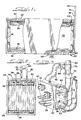
- FIG. 1-3 A preferred embodiment of apparatus for carrying out the foregoing method is illustrated in Figures 1-3. Similar to prior forms of thermal storage units, the present apparatus includes a vessel with generally 20 insulated walls 22, bottom 24 and top cover 26. The cover 26 may be removable to access the interior of the vessel 20.
- a pool of storage liquid 30 is maintained within the vessel; and a plurality of freezing tubes 36 are arrayed, usually in serpentine configuration, within the vessel and immersed in the pool 30.
- the tubes 36 communicate with an inlet pipe 38 and an outlet pipe 40 which in turn are connectable to a refrigerant system, including heat exchangers such as a chiller, and a space air conditioner, neither shown.
- the foregoing apparatus elements are operated during an ice production/storage cycle in a manner to receive cold liquid refrigerant from a chiller (not shown) through pipe 38 and to pass it through the tubes 36 to the outlet pipe 40 whence it is returned to the chiller.
- the cold refrigerant causes the storage liquid in pool 30 to freeze about the tubes 36 and gradually build up an encircling ice envelope surrounding each tube.
- a cold supply cycle may be undertaken by circulating the liquid refrigerant from outlet pipe 40 to an air conditioner (not shown) where it is warmed (absorbs heat) and returning it through inlet pipe 38 to the tubes 36 where the liquid refrigerant is chilled by means of the ice envelopes about the tubes.
- an air conditioner not shown
- the aforementioned chiller, thermal storage unit and air conditioner may be interconnected in a manner that allows for intermittent and alternate cycling and also for overlapped operation. In the latter case both the chiller and thermal storage unit function to concurrently and serially (or in parallel) chill the liquid refrigerant so as to handle the heat load of an air conditioner during peak demand.
- the thermal storage unit is improved by adding supplementary conduits 50 to functionally extend the path of the liquid refrigerant for chilling within the thermal storage unit by contact with free storage liquid during only the cold supply cycle. That is it is essential that the supplementary conduits 50 are not functionally operable to form ice envelopes as that condition would defeat the ability to overcome the aforementioned deficiency of the prior apparatus.
- the supplementary conduits 50 are arrayed in two horizontal runs above the bank of serpentine tubes 36 and the storage liquid pool 30 is maintained to a level above the conduits 50.
- the conduits 50 are preferably provided with fins 52, best seen in Figure 3, to maximize heat transfer surface area; however it is within the ambit of the invention to utilize smooth wall conduits and corrugated and fluted conduits, and the like.
- tubes 36 are connected to the inlet pipe 38 by means of an inlet header 60 which forms a lower compartment of a tri-part manifold generally 62.
- inlet header 60 which forms a lower compartment of a tri-part manifold generally 62.
- plural tubes 36 run in serpentine courses downwardly, within the vessel 20 to a lower manifold 64; and alternate serpentine courses of the tubes 36 extend upwardly from the manifold 64 to a first outlet header 66 which is a central compartment of the tri-part manifold 62.
- Alternate courses of tubes 36 provide counter-directional liquid flow in adjacent courses of tubes. This arrangement compensates for variation in ice thickness in that the rate of ice build up tends to decline along the flow length of a tube serpentine.
- At least one elbow pipe 68 extends from the first outlet header 66 through a first control valve 70 to a "T" union 72 joined to outlet pipe 40.
- first control valve 70 When the first control valve 70 is open, liquid refrigerant introduced through inlet pipe 38 and header 60 may flow through the downward and upward courses of tubes 36 and exit directly from the first outlet header 66 through elbow 68 and valve 70 to the outlet pipe 40.
- the supplementary conduits 50 are also connected to the first outlet header 66 in close proximity to the ends of tubes 36. It will be understood that the conduits 50 are spaced above the tubes 36 a distance of at least approximately one-half the vertical distance between horizontal tube runs so as to be above the ice envelope on the uppermost runs of tubes 36.
- Conduits 50 extend through the upper level of the storage liquid pool 30, above the tubes 36, and are connected to a second outlet header 80 which, in the illustrated embodiment, is in the form of an uppermost compartment of the tri-part manifold 62.
- a second elbow pipe 82 and second control valve 84 are connected between the second outlet header and the "T" union 72 and hence to outlet pipe 40. It may be followed in Figures 2 and 3 that when valve 84 is open liquid refrigerant may flow through the conduits 50 and exit to the outlet pipe 40.
- the apparatus embodiment of figures 1-3 is operated to close the second valve 84 and open the first valve 70 during a storage cycle which causes cold liquid refrigerant supplied through inlet pipe 38 (from a chiller unit not shown) to exit through the first outlet header 66 and elbow pipe 68 to the outlet pipe 40 and not flow through the supplementary conduits 50.
- cold liquid refrigerant supplied through inlet pipe 38 from a chiller unit not shown
- elbow pipe 68 to the outlet pipe 40 and not flow through the supplementary conduits 50.
- the first control valve 70 is closed and the second valve 84 opened. This condition prevents liquid refrigerant from exiting the first outlet manifold 66 through elbow 68 and forces the refrigerant flow to extend through conduits 50 to the second outlet header 80 and thence through elbow pipe 82 to the outlet pipe 40. Since ice is not formed around the conduits 50 during a storage cycle they remain immersed in free storage liquid that is chilled by the ice on the tubes 36 therebelow.
- the tri-part manifold 62 may be of symmetrical construction of corrosion resistant metal, or the like, comprising a single face plate 110 having openings to which all tubes and conduits are connected at one side with two perpendicular divider walls 112, 114 extending from the other side, and having outer angled walls 116, 118 defining the inlet header 60 and second outlet header 80, respectively, and box plate 120 which defines the first outlet header 66.
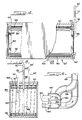
- FIG. 4-6 A modified embodiment of the invention is shown in Figures 4-6 wherein parts similar to those illustrated in Figures 1-3 are designated with the same reference characters bearing prime notations.
- additional supplementary conduits 150 are ranged across the bottom of the vessel 20′ beneath the lowermost runs of tubes 36′.
- the alternating courses of tubes 36′ are independently connected to the inlet pipe 38′ so as to provide counter-directional liquid refrigerant flow in adjacent courses of tubes 36′.
- the lower manifold 64′ is divided horizontally by a wall 160 into an upper entry chamber 162 and a lower outlet chamber 164.
- the ends of alternate course of tubes 36′ are connected, respectively, to chambers 162 and 164.
- a first extension pipe 166 is connected between the entry chamber 162 and the inlet pipe 38′.
- a second extension pipe 168 is connected between the outlet chamber 164 and the elbow pipe 68′ extending from the first outlet header 66′.
- Those courses of tubes 36′ that are connected to the inlet chamber 162 extend, in serpentine form, upwardly and are connected to the first outlet header 66′.
- the alternate courses of tube 36′ connected to the outlet chamber 164 similarly extend downwardly from the inlet header 60′.
- additional supplementary conduits 150 extend from the outlet chamber 164 beneath tubes 36′ horizontally across the bottom of the storage liquid pool 30 and are connected by vertical risers 156 to single upper conduit runs 158, which are spaced between conduits 50′, extending into the second outlet header 80′.
- valve 70′ is open and valve 84′ is closed to deliver cold liquid refrigerant to both the inlet header 60′ and the entry chamber 162.
- the refrigerant will flow in opposite directions through alternate courses of tubes 36′ to the respective outlet chamber 164 and first outlet header 66′ and thence directly through pipes 168 and 68′ to the outlet pipe 40′ (as closed valve 84′ will block any flow through the conduits 50′ and 150).
- valve 70′ closed and valve 84′ open, the liquid refrigerant cannot exit from either outlet chamber 164 through pipe 168 or the first outlet header 66′ through pipe 68′ and is thus forced to flow therefrom through extended paths provided by the conduits 150 (and 158) and 50′ respectively to exit through the second outlet header 80′ and pipe 82′ to the outlet pipe 40′.
- This configuration is believed to be slightly more efficient in that it utilizes free liquid at the bottom of pool 30′ which may not convect upwardly through the ice field on tubes 36′; and also allows for a greater length of supplemental conduit.
- FIG. 7 illustrates a modification of the embodiment of Figures 1-3.
- the bank of tubes 36 ⁇ is spaced from the bottom 24 ⁇ of the vessel 20 ⁇ so as to leave a body of free unfrozen storage liquid beneath the tubes during the ice storage cycle. It is intended that the upper level of the pool 30 ⁇ would cover the upper runs of tubes 36 ⁇ but would not reach the supplementary conduits 50 ⁇ .
- a flexible and inflatable bladder 180 is secured to the vessel bottom wall 24 ⁇ and a source of pressurized gas 184, such as air or carbon dioxide (usually an air pump), is connected through a three way valve 186 to the space between bottom wall 24 ⁇ and bladder 180.
- the valve 186 also has an exhaust port to permit release of gas from the bladder 180.
- the bladder 180 is inflated during the supply cycle whereby it will expand against the lower ice envelopes and lift the free storage liquid to a higher level in vessel 20 ⁇ so as to immerse the supplementary conduits 50.
- the three way valve is actuated to exhaust the bladder 180 which will collapse under the weight of the storage liquid and thereby lower the pool 30 ⁇ below the conduits 50 ⁇ .
- Otherwise operation is similar to the embodiment of Figures 1-3; however since the conduits 50 ⁇ will not be immersed in storage liquid during the storage cycle, and therefore be incapable of ice formation, it is also possible to provide direct connections between tubes 36 ⁇ and conduits 50 ⁇ allowing liquid refrigerant to flow through both during the storage cycle as well as during the supply cycle.
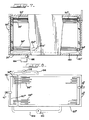
- a further embodiment illustrated in Figure 8 provide for direct extension of tubes 36′′′ into respective supplementary conduits 5′′′ which are located in a tank 190 physically separated from the vessel 20′′′.
- the conduits 50′′′ may comprise one or more rows which end at a discharge header 80′′′ to which an outlet pipe 40′′′ is attached.
- the lower levels of vessel 20′′′ and tank 190 are interconnected by pipes 192, 194 which permit storage liquid to be circulated therebetween.
- a pump 196 in pipe 192 is operable to withdraw liquid from the tank 190; and a two way shut off valve 198 in pipe 194 is operable to block flow of storage liquid from the vessel 20′′′.
- valve 198 in operation during a storage cycle when cold liquid refrigerant flows through tubes 36′′′ and conduits 50′′′ the valve 198 is closed and pump 196 operated to empty the tank 190 (whereby ice cannot be formed on the conduits 50′′′); and during a supply cycle the valve 198 is opened and pump 196 operated continuously to circulate free storage liquid from vessel 20′′′ through tank 190 and across the conduits 50′′′ which will thereby become immersed in the free storage liquid.
- the tank 190 of the embodiment shown in Figure 8 may be geometrically relocated with respect to the vessel 20′′′. For instance it may be located to either side or to either end of the vessel 20′′′. Also tank 190 may be conveniently located above the vessel 20′′′ in which case the pump 196 would be reversed to move liquid from vessel 20′′′ to tank 190 during only the supply cycle and valve 198 could be eliminated and the tank 190 will drain by gravity to be empty of storage liquid during the storage cycle.
- FIG. 9 Still another apparatus embodiment is illustrated in Figure 9. This embodiment is similar to the embodiments of Figures 1 and 7 except that the freezing tubes 36 are directly connected to the supplementary conduits 50, which continuously discharge through outlet header 80, and a separate reservoir 200 is connected by a valve 202 and drain pipe 204 to a point in the pool of storage liquid at vessel wall 22 between the uppermost row of tubes 36 and the lowermost row of conduits 50.
- the reservoir is also connected by a resupply pipe 206, pump 208 and valve 210 to the vessel 20, preferably through the bottom 24.
- some of the storage liquid is drained through open valve 202 into the reservoir 200 where it is retained by closing the valve 210.
- valve 202 is closed and valve 210 is opened for a period to operate pump 208 to transfer liquid from the reservoir 200 back into the vessel 20 so as to raise the level of the free storage liquid to a point above the uppermost conduit 50.
- This plan may be further modified by changing the elevation of reservoir 200 with respect to the vessel 20 and rearranging the valves and pump so as to provide for extracting storage liquid by pumping and returning same to vessel 20 by gravity flow.
Abstract
Description
- This invention relates to thermal storage and more particularly is an improved method and apparatus for utilizing ice which is formed and stored in a vessel.
- Thermal storage equipment of the type which forms ice during off peak energy periods and then makes the ice available as a supply of cold for space conditioning, and the like, is known. In one form of such thermal storage equipment a refrigerant liquid, such as brine or an ethylene glycol solution, is flowed through a channel which is immersed in a pool of freezeable storage liquid, such as water. The pool of water, or the like, is confined within a vessel and the refrigerant channel usually is a form of tubing bent into a serpentine with plural tube runs immersed in the pool. Plural refrigerant channels are usually packed in parallel within the pool and connected between inlet and outlet headers which receive and discharge the refrigerant liquid from, and to, one or more heat exchangers in which the refrigerant liquid is cooled during the ice production cycle, and warmed during the cold supply cycle. The storage liquid is usually agitated during at least certain periods of operation to lessen temperature stratification.
- During the ice production cycle cold refrigerant liquid, at a temperature below the solidification point of the storage liquid within the pool, is continuously produced by mechanical refrigeration, or the like, in one heat exchanger (usually referred to as a "chiller") and flowed to the inlet header through the channels and out of the outlet header and returned to the chiller. The storage liquid will freeze on the channels in the form of surrounding envelopes and gradually develop a substantial thickness of frozen liquid (usually ice). At a point just before the envelopes on parallel adjacent channels contact one another the optimum effective storage capacity will be reached. However, a quantity of unfrozen storage liquid will normally remain free along the walls of the vessel and between adjacent frozen envelopes, and such free liquid will equilibrate at a temperature close to the freezing point.
- During the supply cycle the refrigerant liquid is circulated to a heat exchanger (such as a component of a space air conditioning system), where the refrigerant is warmed, and returned to the channels within the thermal storage unit where it is cooled by the frozen envelopes. However, as each envelope melts internally to form a liquid sleeve around the refrigerant channel, the liquid sleeve will increase in temperature above the storage liquid freezing point and to an extent will partially insulate the channel surface from the remaining frozen envelope. This results in a temporary increase in the temperature of the refrigerant liquid exiting from the outlet header (to above the storage liquid freezing point) thereby lowering the efficiency of the thermal storage unit due to its inability to continuously deliver refrigerant liquid close to the freezing temperature of the storage liquid. The latter condition, although temporary, will continue until the frozen envelope is opened by heat convection of the liquid sleeve whereupon the agitated free liquid, exterior of the envelope, also becomes available to chill the tube surface. The condition may also be partially relieved at such time that the buoyant effect of the free liquid in the vessel lifts the frozen envelope sufficiently to urge the ice against the lower portions of tube surface.
- Thus it would be highly advantageous to overcome the effect of the liquid sleeve that forms between tube and frozen envelope during an early part of the supply cycle.
- Accordingly, it is a primary object of the present invention to provide an improved method and apparatus for continuously obtaining refrigerant liquid from thermal storage equipment at a more uniform temperature just above the freezing temperature of the storage liquid.
- It is another object of the present invention to provide an improved method and apparatus for evening the temperature at which liquid refrigerant exits a thermal storage unit throughout a cold supply cycle.
- It is a further object of the present invention to provide an improved method and apparatus for supplying a substantially constant temperature flow of cold liquid refrigerant from an ice storage unit.
- It is a still further object of the present invention to provide an ice thermal storage apparatus having supplemental conduits immersible in free storage liquid and connected to add to the flow path of liquid refrigerant that also is passed through ice enveloped channels.
- It is yet another object of the present invention to provide a method for selectively adding to the flow paths of liquid refrigerant through an ice storage unit within conduits chilled with free storage liquid.
- It is still another object of the present invention to provide an ice thermal storage apparatus having supplemental conduits immersible in free storage liquid and connected to receive partly chilled liquid refrigerant from ice enveloped tubes.
- According to one aspect, the present invention provides a method for thermal storage and recovery whereby frozen liquid is formed and stored during a storage cycle by passing cold refrigerant liquid through one or more primary flow paths confined within a storage zone of storage liquid thereby creating envelopes of frozen storage liquid around the primary flow paths, comprising:
during a supply cycle flowing relatively warmer refrigerant liquid through said primary flow paths within said envelopes and additionally flowing refrigerant liquid through additional flow paths or additions, said additions being immersed in storage liquid that is cooled by said envelopes. - The cumulative effect of refrigerant liquid transiting an additional flow path immersed in free liquid and the primary flow path surrounded by a frozen envelope being functionally sufficient to reduce the refrigerant liquid temperature to about the temperature of the free liquid. Furthermore, during the storage cycle a frozen envelope is formed by chilled refrigerant only on the primary flow path through a channel constantly immersed in the storage liquid. Preferably such supplementing of the cooling is accomplished by subsequently passing the refrigerant liquid serially through a conduit immersed in free storage liquid that is chilled by the frozen envelope so as to bring the refrigerant liquid to close to the free storage liquid temperature.
- According to a further aspect of the present invention, there is provided a thermal storage apparatus wherein a liquid refrigerant is flowed through a channel immersed in a pool of freezeable storage liquid contained within a vessel for the purpose of forming frozen storage liquid along said channel during a storage cycle and for melting the frozen storage liquid during a cold supply cycle, comprising;
a supplemental conduit immersible in free unfrozen storage liquid and a said supplemental conduit being connectable to said channel during said cold supply cycle;
and means to cause said supplemental conduit to be functionally inoperative during said storage cycle; - In preferred embodiments of the invention the flow path addition for refrigerant liquid is through an area of the liquid pool within the thermal storage vessel which area is kept free of a frozen envelope; that is each flow path addition may be within the vessel and spaced from an envelope or from a frozen envelope formation zone. However, it is also possible to locate each flow path addition either within or outside of the thermal storage vessel but remote from the normal storage liquid pool geometry and to move free liquid into contact with the flow path addition only during the supply cycle when refrigerant liquid is chilled by frozen storage liquid in the vessel.
- Further objects and advantages of the invention will become apparent from the following detailed description of preferred embodiments of the present invention taken in conjunction with the drawings wherein:
- Figure 1 is a side elevation view of a thermal storage apparatus with parts removed to show details of a preferred embodiment of the present invention;
- Figure 2 is an end view of the apparatus of Figure 1;
- Figure 3 is a detailed perspective view in partial section of a portion of the apparatus of Figure 1;
- Figure 4 is a side elevation of a thermal storage apparatus with parts removed to show details of a modified embodiment of the invention;
- Figure 5 is an end view of the apparatus of Figure 4;
- Figure 6 is a detailed view of a portion of the apparatus shown in Figure 4;
- Figure 7 is a side elevation view of another embodiment of the present invention;
- Figure 8 is a plan view of a further embodiment of the present invention; and
- Figure 9 is a side elevation of still another embodiment of the present invention.
- It has been observed that during a cold supply cycle the liquid refrigerant exiting a thermal storage unit, of the type which freezes storage liquid on the surface of refrigerant circulation channels during a storage cycle, will initially approach the freezing temperature at the beginning of the supply cycle and then increase as a sleeve or annulus of melted storage liquid forms between each channel and the frozen envelope. According to the present invention this undesirable temperature increase may be lessened and usually eliminated by maintaining a quantity of unfrozen storage liquid, herein referred to as free storage liquid, in contact with the frozen liquid, herein referred to as ice, within a thermal storage unit and during only the supply cycle providing flow path additions for the liquid refrigerant (preferably after it passes through primary flow paths comprising enveloped channels) through a supplemental zone immersed in free storage liquid.
- By thus providing flow path additions the liquid refrigerant is further cooled by the free storage liquid that is, in turn, chilled by the ice present in the storage unit; and each flow path addition is suitably adjusted by length, or by other modification of the surface for heat transfer between the liquid refrigerant and the storage liquid, to lower the liquid refrigerant temperature to just above the temperature of the free liquid and the ice.
- The supplemental zone excludes the channels on which ice is frozen and is not subject to the formation of ice therein. It may be within or directly adjoin and receive a flow of liquid from the pool of storage liquid wherein the channels for freezing are located, but the supplemental zone will not contain channels functioning to form ice. It is also possible to separate the supplemental zone from the pool by flowing free storage liquid to the supplemental zone during only the cold supply cycle.
- Preferably the liquid refrigerant flow path additions are series extensions of primary flow paths and may be provided in a number of ways, such as by periodically diverting the liquid refrigerant from a channel outlet and through a supplementary conduit which is continuously immersed in the storage liquid and/or by continuously flowing the liquid refrigerant through supplementary conduit that is immersed in free storage liquid only during the supply cycle.
- For convenience of expression the terms "tube" (tubes and tubing) and "ice" are used throughout to refer to a physical channel for the primary flow path for liquid refrigerant, and to a frozen form or state of the storage liquid, respectively. However, it will be understood that the flow path channel may be selected from several known structures in addition to tubes, such as spaced plates, pressed and welded plates etc., and the storage liquid may be water or other known freezable liquids and liquid solutions which have a latent heat of fusion when undergoing phase change between solid and liquid.
- A preferred embodiment of apparatus for carrying out the foregoing method is illustrated in Figures 1-3. Similar to prior forms of thermal storage units, the present apparatus includes a vessel with generally 20 insulated
walls 22,bottom 24 andtop cover 26. Thecover 26 may be removable to access the interior of thevessel 20. - A pool of storage liquid 30 is maintained within the vessel; and a plurality of
freezing tubes 36 are arrayed, usually in serpentine configuration, within the vessel and immersed in the pool 30. Thetubes 36 communicate with aninlet pipe 38 and anoutlet pipe 40 which in turn are connectable to a refrigerant system, including heat exchangers such as a chiller, and a space air conditioner, neither shown. - In normal operation the foregoing apparatus elements are operated during an ice production/storage cycle in a manner to receive cold liquid refrigerant from a chiller (not shown) through
pipe 38 and to pass it through thetubes 36 to theoutlet pipe 40 whence it is returned to the chiller. During this cycle the cold refrigerant causes the storage liquid in pool 30 to freeze about thetubes 36 and gradually build up an encircling ice envelope surrounding each tube. Normally, if the storage liquid is agitated, it is inefficient to continue to build ice beyond the point just before there is contact between the ice envelopes onadjacent tubes 36 on parallel vertical serpentine circuits and the storage cycle is completed upon reaching that condition which may leave a quantity of free, unfrozen storage liquid at the top and bottom of the vessel and between ice envelopes. - Thereafter a cold supply cycle may be undertaken by circulating the liquid refrigerant from
outlet pipe 40 to an air conditioner (not shown) where it is warmed (absorbs heat) and returning it throughinlet pipe 38 to thetubes 36 where the liquid refrigerant is chilled by means of the ice envelopes about the tubes. It will be understood that the aforementioned chiller, thermal storage unit and air conditioner may be interconnected in a manner that allows for intermittent and alternate cycling and also for overlapped operation. In the latter case both the chiller and thermal storage unit function to concurrently and serially (or in parallel) chill the liquid refrigerant so as to handle the heat load of an air conditioner during peak demand. - According to an embodiment of the present invention the thermal storage unit is improved by adding
supplementary conduits 50 to functionally extend the path of the liquid refrigerant for chilling within the thermal storage unit by contact with free storage liquid during only the cold supply cycle. That is it is essential that thesupplementary conduits 50 are not functionally operable to form ice envelopes as that condition would defeat the ability to overcome the aforementioned deficiency of the prior apparatus. - In the embodiment of Figure 1-3 the
supplementary conduits 50 are arrayed in two horizontal runs above the bank ofserpentine tubes 36 and the storage liquid pool 30 is maintained to a level above theconduits 50. Theconduits 50 are preferably provided withfins 52, best seen in Figure 3, to maximize heat transfer surface area; however it is within the ambit of the invention to utilize smooth wall conduits and corrugated and fluted conduits, and the like. - It may be best seen in Figure 3 that at an upper end of the
vessel 20 thetubes 36 are connected to theinlet pipe 38 by means of aninlet header 60 which forms a lower compartment of a tri-part manifold generally 62. In the apparatus illustratedplural tubes 36 run in serpentine courses downwardly, within thevessel 20 to alower manifold 64; and alternate serpentine courses of thetubes 36 extend upwardly from the manifold 64 to afirst outlet header 66 which is a central compartment of thetri-part manifold 62. Alternate courses oftubes 36 provide counter-directional liquid flow in adjacent courses of tubes. This arrangement compensates for variation in ice thickness in that the rate of ice build up tends to decline along the flow length of a tube serpentine. At least oneelbow pipe 68 extends from thefirst outlet header 66 through afirst control valve 70 to a "T"union 72 joined tooutlet pipe 40. When thefirst control valve 70 is open, liquid refrigerant introduced throughinlet pipe 38 andheader 60 may flow through the downward and upward courses oftubes 36 and exit directly from thefirst outlet header 66 throughelbow 68 andvalve 70 to theoutlet pipe 40. - The
supplementary conduits 50 are also connected to thefirst outlet header 66 in close proximity to the ends oftubes 36. It will be understood that theconduits 50 are spaced above the tubes 36 a distance of at least approximately one-half the vertical distance between horizontal tube runs so as to be above the ice envelope on the uppermost runs oftubes 36.Conduits 50 extend through the upper level of the storage liquid pool 30, above thetubes 36, and are connected to asecond outlet header 80 which, in the illustrated embodiment, is in the form of an uppermost compartment of thetri-part manifold 62. Asecond elbow pipe 82 andsecond control valve 84 are connected between the second outlet header and the "T"union 72 and hence tooutlet pipe 40. It may be followed in Figures 2 and 3 that whenvalve 84 is open liquid refrigerant may flow through theconduits 50 and exit to theoutlet pipe 40. - The apparatus embodiment of figures 1-3 is operated to close the
second valve 84 and open thefirst valve 70 during a storage cycle which causes cold liquid refrigerant supplied through inlet pipe 38 (from a chiller unit not shown) to exit through thefirst outlet header 66 andelbow pipe 68 to theoutlet pipe 40 and not flow through thesupplementary conduits 50. Thus ice will be formed in the pool 30 only on thetubes 36 and not onconduits 50 nor in the zone of pool 30 through which theconduits 50 extend. - During a supply cycle the
first control valve 70 is closed and thesecond valve 84 opened. This condition prevents liquid refrigerant from exiting thefirst outlet manifold 66 throughelbow 68 and forces the refrigerant flow to extend throughconduits 50 to thesecond outlet header 80 and thence throughelbow pipe 82 to theoutlet pipe 40. Since ice is not formed around theconduits 50 during a storage cycle they remain immersed in free storage liquid that is chilled by the ice on thetubes 36 therebelow. - It is to be further noted that provision is made to agitate the storage liquid pool during at least portions of the cycles so as to minimize temperature stratification and promote uniform ice buildup and ice melt. This is shown in Figure 1 in the form of an air supply, such as
pump 100 andconnector hose 102, at thevessel bottom 24. - Furthermore it is to be noted that while the
aforementioned headers tri-part manifold 62 may be of symmetrical construction of corrosion resistant metal, or the like, comprising asingle face plate 110 having openings to which all tubes and conduits are connected at one side with twoperpendicular divider walls walls inlet header 60 andsecond outlet header 80, respectively, andbox plate 120 which defines thefirst outlet header 66. - A modified embodiment of the invention is shown in Figures 4-6 wherein parts similar to those illustrated in Figures 1-3 are designated with the same reference characters bearing prime notations. In this embodiment additional
supplementary conduits 150 are ranged across the bottom of thevessel 20′ beneath the lowermost runs oftubes 36′. Additionally the alternating courses oftubes 36′ are independently connected to theinlet pipe 38′ so as to provide counter-directional liquid refrigerant flow in adjacent courses oftubes 36′. - In the embodiment of Figures 4-6 the
lower manifold 64′ is divided horizontally by awall 160 into anupper entry chamber 162 and alower outlet chamber 164. The ends of alternate course oftubes 36′ are connected, respectively, tochambers first extension pipe 166 is connected between theentry chamber 162 and theinlet pipe 38′. Asecond extension pipe 168 is connected between theoutlet chamber 164 and theelbow pipe 68′ extending from thefirst outlet header 66′. Those courses oftubes 36′ that are connected to theinlet chamber 162 extend, in serpentine form, upwardly and are connected to thefirst outlet header 66′. The alternate courses oftube 36′ connected to theoutlet chamber 164 similarly extend downwardly from theinlet header 60′. Finally the additionalsupplementary conduits 150 extend from theoutlet chamber 164 beneathtubes 36′ horizontally across the bottom of the storage liquid pool 30 and are connected byvertical risers 156 to single upper conduit runs 158, which are spaced betweenconduits 50′, extending into thesecond outlet header 80′. whencontrol valves 70′, 84′, which may be solenoid actuated, are operated the flow will be similar to that described for the first described embodiment. - That is during a
storage cycle valve 70′ is open andvalve 84′ is closed to deliver cold liquid refrigerant to both theinlet header 60′ and theentry chamber 162. The refrigerant will flow in opposite directions through alternate courses oftubes 36′ to therespective outlet chamber 164 andfirst outlet header 66′ and thence directly throughpipes outlet pipe 40′ (asclosed valve 84′ will block any flow through theconduits 50′ and 150). Similarly during a supply cycle, withvalve 70′ closed andvalve 84′ open, the liquid refrigerant cannot exit from eitheroutlet chamber 164 throughpipe 168 or thefirst outlet header 66′ throughpipe 68′ and is thus forced to flow therefrom through extended paths provided by the conduits 150 (and 158) and 50′ respectively to exit through thesecond outlet header 80′ andpipe 82′ to theoutlet pipe 40′. This configuration is believed to be slightly more efficient in that it utilizes free liquid at the bottom of pool 30′ which may not convect upwardly through the ice field ontubes 36′; and also allows for a greater length of supplemental conduit. - It is also possible to further modify the apparatus of Figures 4-6, particularly where smooth non-finned conduits are employed, to train one or more conduit runs between the alternate courses of
serpentine tubes 36 in the longitudinal spaces that remain unfrozen between adjacent ice envelopes. - Figure 7 illustrates a modification of the embodiment of Figures 1-3. In this apparatus the bank of
tubes 36˝ is spaced from the bottom 24˝ of thevessel 20˝ so as to leave a body of free unfrozen storage liquid beneath the tubes during the ice storage cycle. It is intended that the upper level of the pool 30˝ would cover the upper runs oftubes 36˝ but would not reach thesupplementary conduits 50˝. A flexible andinflatable bladder 180 is secured to thevessel bottom wall 24˝ and a source ofpressurized gas 184, such as air or carbon dioxide (usually an air pump), is connected through a threeway valve 186 to the space betweenbottom wall 24˝ andbladder 180. Thevalve 186 also has an exhaust port to permit release of gas from thebladder 180. In operation thebladder 180 is inflated during the supply cycle whereby it will expand against the lower ice envelopes and lift the free storage liquid to a higher level invessel 20˝ so as to immerse thesupplementary conduits 50. During the storage cycle the three way valve is actuated to exhaust thebladder 180 which will collapse under the weight of the storage liquid and thereby lower the pool 30˝ below theconduits 50˝. Otherwise operation is similar to the embodiment of Figures 1-3; however since theconduits 50˝ will not be immersed in storage liquid during the storage cycle, and therefore be incapable of ice formation, it is also possible to provide direct connections betweentubes 36˝ andconduits 50˝ allowing liquid refrigerant to flow through both during the storage cycle as well as during the supply cycle. - A further embodiment illustrated in Figure 8 provide for direct extension of
tubes 36‴ into respective supplementary conduits 5‴ which are located in atank 190 physically separated from thevessel 20‴. Theconduits 50‴ may comprise one or more rows which end at adischarge header 80‴ to which anoutlet pipe 40‴ is attached. The lower levels ofvessel 20‴ andtank 190 are interconnected bypipes pump 196 inpipe 192 is operable to withdraw liquid from thetank 190; and a two way shut offvalve 198 inpipe 194 is operable to block flow of storage liquid from thevessel 20‴. Thus in operation during a storage cycle when cold liquid refrigerant flows throughtubes 36‴ andconduits 50‴ thevalve 198 is closed and pump 196 operated to empty the tank 190 (whereby ice cannot be formed on theconduits 50‴); and during a supply cycle thevalve 198 is opened and pump 196 operated continuously to circulate free storage liquid fromvessel 20‴ throughtank 190 and across theconduits 50‴ which will thereby become immersed in the free storage liquid. - The
tank 190 of the embodiment shown in Figure 8 may be geometrically relocated with respect to thevessel 20‴. For instance it may be located to either side or to either end of thevessel 20‴. Alsotank 190 may be conveniently located above thevessel 20‴ in which case thepump 196 would be reversed to move liquid fromvessel 20‴ totank 190 during only the supply cycle andvalve 198 could be eliminated and thetank 190 will drain by gravity to be empty of storage liquid during the storage cycle. - Still another apparatus embodiment is illustrated in Figure 9. This embodiment is similar to the embodiments of Figures 1 and 7 except that the freezing
tubes 36 are directly connected to thesupplementary conduits 50, which continuously discharge throughoutlet header 80, and aseparate reservoir 200 is connected by avalve 202 anddrain pipe 204 to a point in the pool of storage liquid atvessel wall 22 between the uppermost row oftubes 36 and the lowermost row ofconduits 50. The reservoir is also connected by aresupply pipe 206, pump 208 andvalve 210 to thevessel 20, preferably through the bottom 24. During the storage cycle some of the storage liquid is drained throughopen valve 202 into thereservoir 200 where it is retained by closing thevalve 210. Thus the upper level of the storage liquid pool 30 will be maintained below theconduits 50 and no ice will be formed thereon. During the supply cycle thevalve 202 is closed andvalve 210 is opened for a period to operatepump 208 to transfer liquid from thereservoir 200 back into thevessel 20 so as to raise the level of the free storage liquid to a point above theuppermost conduit 50. This plan may be further modified by changing the elevation ofreservoir 200 with respect to thevessel 20 and rearranging the valves and pump so as to provide for extracting storage liquid by pumping and returning same tovessel 20 by gravity flow.
Claims (26)
during a supply cycle flowing relatively warmer refrigerant liquid through said primary flow paths within said envelopes and additionally flowing refrigerant liquid through additional flow paths or additions, said additions being immersed in storage liquid that is cooled by said envelopes.
maintaining a quantity of unfrozen free storage liquid within said storage zone during said storage cycle;
extending said primary flow paths through conduits located in a supplemental zone;
and flowing either said refrigerant liquid through the conduits or said free storage liquid from said storage zone into said supplemental zone during only a supply cycle when said frozen liquid and said free storage liquid is employed to cool said refrigerant liquid.
a supplemental conduit immersible in free unfrozen storage liquid and a said supplemental conduit being connectable to said channel during said cold supply cycle;
and means to cause said supplemental conduit to be functionally inoperative during said storage cycle.
a supplemental conduit serially connected to said channels to receive refrigerant liquid therefrom, said supplemental conduit being located in a zone in communication with said pool of storage liquid;
and means to flow either said refrigerant liquid or said free storage liquid in said zone during only a cold supply cycle when said frozen liquid is employed to cool said refrigerant liquid.
supplemental conduits immersed in said pool of liquid;
valve means operable to connect said supplemental conduit in series to said tube runs to receive refrigerant flow during said cold supply cycle and to disconnect said supplemental conduits from said tube runs during said storage cycle, whereby frozen liquid is formed only on said tube runs and during the cold supply cycle said free storage liquid in said vessel, which is cooled by the frozen storage liquid about said tubes, serves to chill said refrigerant flowing through said supplemental conduit from said tube runs during said cold supply cycle.
a face plate adapted to be connected at one side to said tubes and conduits;
at least one divider wall extending from said face plate opposite to said one side;
enclosing walls connected between said face plate and said divider wall to form at least two headers; one said header adapted to receive only the discharge ends of all of said conduits and the other of said headers adapted to receive both the inlet ends of said conduits and the outlet ends of said tubes.
Applications Claiming Priority (2)
| Application Number | Priority Date | Filing Date | Title |
|---|---|---|---|
| US07/155,869 US4831831A (en) | 1988-02-16 | 1988-02-16 | Thermal storage unit with coil extension during melt |
| US155869 | 1988-02-16 |
Publications (2)
| Publication Number | Publication Date |
|---|---|
| EP0329445A2 true EP0329445A2 (en) | 1989-08-23 |
| EP0329445A3 EP0329445A3 (en) | 1991-03-27 |
Family
ID=22557104
Family Applications (1)
| Application Number | Title | Priority Date | Filing Date |
|---|---|---|---|
| EP19890301509 Withdrawn EP0329445A3 (en) | 1988-02-16 | 1989-02-16 | Thermal storage unit having an additional refrigerant flow path |
Country Status (19)
| Country | Link |
|---|---|
| US (1) | US4831831A (en) |
| EP (1) | EP0329445A3 (en) |
| JP (1) | JPH01252837A (en) |
| KR (1) | KR930006413B1 (en) |
| CN (1) | CN1013301B (en) |
| AR (1) | AR243670A1 (en) |
| AU (1) | AU599558B2 (en) |
| BR (1) | BR8900673A (en) |
| CA (1) | CA1307932C (en) |
| DK (1) | DK166928B1 (en) |
| FI (1) | FI890744A (en) |
| IL (1) | IL88828A (en) |
| NO (1) | NO169677C (en) |
| NZ (1) | NZ227581A (en) |
| PH (1) | PH24941A (en) |
| PL (1) | PL277741A1 (en) |
| PT (1) | PT89723B (en) |
| RU (1) | RU1794234C (en) |
| ZA (1) | ZA89188B (en) |
Cited By (1)
| Publication number | Priority date | Publication date | Assignee | Title |
|---|---|---|---|---|
| EP0942239A2 (en) * | 1998-03-13 | 1999-09-15 | Hitachi, Ltd. | Ice thermal storage type air-conditioner and ice thermal storage tank |
Families Citing this family (19)
| Publication number | Priority date | Publication date | Assignee | Title |
|---|---|---|---|---|
| US5596877A (en) | 1995-08-16 | 1997-01-28 | Baltimore Aircoil Company, Inc. | Header and coil arrangement for cooling apparatus |
| US5823010A (en) * | 1997-05-30 | 1998-10-20 | Chao; Ching-I | Air condition installation adjustable in storing and dispensing coolness |
| CN1302366A (en) * | 1998-05-22 | 2001-07-04 | 伊沃普欧国际公司 | Ice thermal storage coil system and methods |
| US6178770B1 (en) | 1998-10-22 | 2001-01-30 | Evapco International, Inc. | Ice-on-coil thermal storage apparatus and method |
| US6247522B1 (en) | 1998-11-04 | 2001-06-19 | Baltimore Aircoil Company, Inc. | Heat exchange members for thermal storage apparatus |
| US6158499A (en) * | 1998-12-23 | 2000-12-12 | Fafco, Inc. | Method and apparatus for thermal energy storage |
| US6138746A (en) * | 1999-02-24 | 2000-10-31 | Baltimore Aircoil Company, Inc. | Cooling coil for a thermal storage tower |
| US6532749B2 (en) | 1999-09-22 | 2003-03-18 | The Coca-Cola Company | Stirling-based heating and cooling device |
| US6272867B1 (en) | 1999-09-22 | 2001-08-14 | The Coca-Cola Company | Apparatus using stirling cooler system and methods of use |
| US6266963B1 (en) | 1999-10-05 | 2001-07-31 | The Coca-Cola Company | Apparatus using stirling cooler system and methods of use |
| US6581389B2 (en) | 2001-03-21 | 2003-06-24 | The Coca-Cola Company | Merchandiser using slide-out stirling refrigeration deck |
| US6550255B2 (en) | 2001-03-21 | 2003-04-22 | The Coca-Cola Company | Stirling refrigeration system with a thermosiphon heat exchanger |
| TWI261513B (en) * | 2002-04-30 | 2006-09-11 | Carrier Comm Refrigeration Inc | Refrigerated merchandiser with foul-resistant condenser |
| JP4324187B2 (en) * | 2006-10-25 | 2009-09-02 | トヨタ自動車株式会社 | Heat storage device |
| JP4508204B2 (en) * | 2007-03-08 | 2010-07-21 | セイコーエプソン株式会社 | Tuning fork type piezoelectric vibrator |
| US20110079025A1 (en) * | 2009-10-02 | 2011-04-07 | Thermo King Corporation | Thermal storage device with ice thickness detection and control methods |
| US11668534B2 (en) | 2018-12-13 | 2023-06-06 | Baltimore Aircoil Company, Inc. | Fan array fault response control system |
| CN112554374B (en) * | 2021-02-19 | 2021-04-20 | 青竹湖建设集团有限公司 | Green building wall structure and green building |
| US11680754B2 (en) | 2021-04-09 | 2023-06-20 | Trane International Inc. | Systems and methods for thermal storage solid phase formation removal |
Citations (4)
| Publication number | Priority date | Publication date | Assignee | Title |
|---|---|---|---|---|
| US2246401A (en) * | 1933-10-03 | 1941-06-17 | Carrier Corp | Method and means for providing refrigeration |
| DE2934321A1 (en) * | 1979-08-24 | 1981-06-11 | Interatom Internationale Atomreaktorbau Gmbh, 5060 Bergisch Gladbach | Solar latent heat storage unit - has heat exchangers in top and bottom of vessel containing storage medium |
| US4294083A (en) * | 1980-04-07 | 1981-10-13 | Barton King | Air conditioning system |
| EP0181137A2 (en) * | 1984-11-05 | 1986-05-14 | Calmac Manufacturing Corporation | Method of cyclic air conditioning with cogeneration of ice |
Family Cites Families (3)
| Publication number | Priority date | Publication date | Assignee | Title |
|---|---|---|---|---|
| CH439854A (en) * | 1964-06-03 | 1967-07-15 | Karnath Guenther | Process for cooling milk in suction milking systems and means for carrying out the same |
| US3672183A (en) * | 1970-01-21 | 1972-06-27 | Arthur Bernstein | Ice bank heat exchanger |
| US4951739A (en) * | 1988-01-28 | 1990-08-28 | Baltimore Aircoil Company, Inc. | Thermal storage with tubular containers of storage mediums |
-
1988
- 1988-02-16 US US07/155,869 patent/US4831831A/en not_active Expired - Lifetime
- 1988-12-29 IL IL88828A patent/IL88828A/en not_active IP Right Cessation
-
1989
- 1989-01-10 ZA ZA89188A patent/ZA89188B/en unknown
- 1989-01-10 AU AU28338/89A patent/AU599558B2/en not_active Ceased
- 1989-01-10 NZ NZ227581A patent/NZ227581A/en unknown
- 1989-01-18 NO NO890221A patent/NO169677C/en unknown
- 1989-01-24 CA CA000589007A patent/CA1307932C/en not_active Expired - Fee Related
- 1989-02-09 PH PH38178A patent/PH24941A/en unknown
- 1989-02-15 PT PT89723A patent/PT89723B/en not_active IP Right Cessation
- 1989-02-15 JP JP1033880A patent/JPH01252837A/en active Granted
- 1989-02-15 RU SU894613469A patent/RU1794234C/en active
- 1989-02-15 AR AR89313216A patent/AR243670A1/en active
- 1989-02-15 CN CN89100814A patent/CN1013301B/en not_active Expired
- 1989-02-15 BR BR898900673A patent/BR8900673A/en not_active IP Right Cessation
- 1989-02-16 DK DK072589A patent/DK166928B1/en not_active IP Right Cessation
- 1989-02-16 FI FI890744A patent/FI890744A/en not_active IP Right Cessation
- 1989-02-16 PL PL27774189A patent/PL277741A1/en unknown
- 1989-02-16 EP EP19890301509 patent/EP0329445A3/en not_active Withdrawn
- 1989-02-16 KR KR1019890001895A patent/KR930006413B1/en not_active IP Right Cessation
Patent Citations (4)
| Publication number | Priority date | Publication date | Assignee | Title |
|---|---|---|---|---|
| US2246401A (en) * | 1933-10-03 | 1941-06-17 | Carrier Corp | Method and means for providing refrigeration |
| DE2934321A1 (en) * | 1979-08-24 | 1981-06-11 | Interatom Internationale Atomreaktorbau Gmbh, 5060 Bergisch Gladbach | Solar latent heat storage unit - has heat exchangers in top and bottom of vessel containing storage medium |
| US4294083A (en) * | 1980-04-07 | 1981-10-13 | Barton King | Air conditioning system |
| EP0181137A2 (en) * | 1984-11-05 | 1986-05-14 | Calmac Manufacturing Corporation | Method of cyclic air conditioning with cogeneration of ice |
Cited By (2)
| Publication number | Priority date | Publication date | Assignee | Title |
|---|---|---|---|---|
| EP0942239A2 (en) * | 1998-03-13 | 1999-09-15 | Hitachi, Ltd. | Ice thermal storage type air-conditioner and ice thermal storage tank |
| EP0942239A3 (en) * | 1998-03-13 | 2002-06-05 | Hitachi, Ltd. | Ice thermal storage type air-conditioner and ice thermal storage tank |
Also Published As
| Publication number | Publication date |
|---|---|
| KR930006413B1 (en) | 1993-07-14 |
| ZA89188B (en) | 1989-09-27 |
| NO169677C (en) | 1992-07-22 |
| IL88828A (en) | 1993-08-18 |
| JPH01252837A (en) | 1989-10-09 |
| NZ227581A (en) | 1991-04-26 |
| CN1036632A (en) | 1989-10-25 |
| PT89723B (en) | 1994-02-28 |
| PH24941A (en) | 1990-12-26 |
| EP0329445A3 (en) | 1991-03-27 |
| AU599558B2 (en) | 1990-07-19 |
| RU1794234C (en) | 1993-02-07 |
| KR890013453A (en) | 1989-09-23 |
| PL277741A1 (en) | 1990-01-22 |
| FI890744A0 (en) | 1989-02-16 |
| AR243670A1 (en) | 1993-08-31 |
| CA1307932C (en) | 1992-09-29 |
| IL88828A0 (en) | 1989-07-31 |
| BR8900673A (en) | 1989-10-10 |
| NO169677B (en) | 1992-04-13 |
| PT89723A (en) | 1989-10-04 |
| NO890221D0 (en) | 1989-01-18 |
| AU2833889A (en) | 1989-08-17 |
| DK72589D0 (en) | 1989-02-16 |
| CN1013301B (en) | 1991-07-24 |
| FI890744A (en) | 1989-08-17 |
| DK166928B1 (en) | 1993-08-02 |
| US4831831A (en) | 1989-05-23 |
| DK72589A (en) | 1989-08-17 |
| JPH0449017B2 (en) | 1992-08-10 |
| NO890221L (en) | 1989-08-17 |
Similar Documents
| Publication | Publication Date | Title |
|---|---|---|
| US4831831A (en) | Thermal storage unit with coil extension during melt | |
| US5072596A (en) | Ice building chilled water system and method | |
| US5168724A (en) | Ice building, chilled water system | |
| US5090207A (en) | Ice building, chilled water system and method | |
| KR100225276B1 (en) | Operation method and apparatus therefor of heat storage system | |
| US4656836A (en) | Pressurized, ice-storing chilled water system | |
| WO1990009554A1 (en) | Ice building, chilled water system and method | |
| US4544028A (en) | Heat accumulator | |
| US2308164A (en) | Ice making apparatus | |
| US476832A (en) | shipley | |
| SU1331458A1 (en) | Accumulator of natural cold for cooling milk at stock-raising farms | |
| JP2004205127A (en) | Low temperature air layer forming system with cold heat storage floor and its operating method | |
| US1180534A (en) | Ice-machine. | |
| JPS6333051B2 (en) | ||
| US1790426A (en) | Henby leonabb kelley anb balph kelley | |
| JP2001090997A (en) | Ice storage device | |
| RU2197081C1 (en) | Apparatus for cooling milk with natural cold | |
| JPS6035019Y2 (en) | Ice-making plate in ice-making machine | |
| JPS5832640B2 (en) | Freeze-thaw sludge treatment equipment | |
| US1156832A (en) | Ice-machine. | |
| JPH102585A (en) | Dynamic ice heat storage device | |
| EP0301066A4 (en) | Ice building, chilled water system and method | |
| JPH08226681A (en) | Ice storage apparatus | |
| JPH02287079A (en) | Brine refrigerator device | |
| JPH1163580A (en) | Heat storage device |
Legal Events
| Date | Code | Title | Description |
|---|---|---|---|
| PUAI | Public reference made under article 153(3) epc to a published international application that has entered the european phase |
Free format text: ORIGINAL CODE: 0009012 |
|
| AK | Designated contracting states |
Kind code of ref document: A2 Designated state(s): AT BE CH DE ES FR GB IT LI LU NL SE |
|
| PUAL | Search report despatched |
Free format text: ORIGINAL CODE: 0009013 |
|
| AK | Designated contracting states |
Kind code of ref document: A3 Designated state(s): AT BE CH DE ES FR GB IT LI LU NL SE |
|
| 17P | Request for examination filed |
Effective date: 19910521 |
|
| 17Q | First examination report despatched |
Effective date: 19920227 |
|
| STAA | Information on the status of an ep patent application or granted ep patent |
Free format text: STATUS: THE APPLICATION IS DEEMED TO BE WITHDRAWN |
|
| 18D | Application deemed to be withdrawn |
Effective date: 19930427 |