EP0331451A1 - Hand scanner type image input/output device - Google Patents
Hand scanner type image input/output device Download PDFInfo
- Publication number
- EP0331451A1 EP0331451A1 EP89302011A EP89302011A EP0331451A1 EP 0331451 A1 EP0331451 A1 EP 0331451A1 EP 89302011 A EP89302011 A EP 89302011A EP 89302011 A EP89302011 A EP 89302011A EP 0331451 A1 EP0331451 A1 EP 0331451A1
- Authority
- EP
- European Patent Office
- Prior art keywords
- main body
- output device
- image input
- type image
- opening
- Prior art date
- Legal status (The legal status is an assumption and is not a legal conclusion. Google has not performed a legal analysis and makes no representation as to the accuracy of the status listed.)
- Granted
Links
Images


Classifications
-
- H—ELECTRICITY
- H04—ELECTRIC COMMUNICATION TECHNIQUE
- H04N—PICTORIAL COMMUNICATION, e.g. TELEVISION
- H04N1/00—Scanning, transmission or reproduction of documents or the like, e.g. facsimile transmission; Details thereof
- H04N1/04—Scanning arrangements, i.e. arrangements for the displacement of active reading or reproducing elements relative to the original or reproducing medium, or vice versa
- H04N1/10—Scanning arrangements, i.e. arrangements for the displacement of active reading or reproducing elements relative to the original or reproducing medium, or vice versa using flat picture-bearing surfaces
- H04N1/107—Scanning arrangements, i.e. arrangements for the displacement of active reading or reproducing elements relative to the original or reproducing medium, or vice versa using flat picture-bearing surfaces with manual scanning
- H04N1/1077—Arrangements for facilitating movement over the scanned medium, e.g. disposition of rollers
-
- H—ELECTRICITY
- H04—ELECTRIC COMMUNICATION TECHNIQUE
- H04N—PICTORIAL COMMUNICATION, e.g. TELEVISION
- H04N1/00—Scanning, transmission or reproduction of documents or the like, e.g. facsimile transmission; Details thereof
- H04N1/04—Scanning arrangements, i.e. arrangements for the displacement of active reading or reproducing elements relative to the original or reproducing medium, or vice versa
- H04N1/10—Scanning arrangements, i.e. arrangements for the displacement of active reading or reproducing elements relative to the original or reproducing medium, or vice versa using flat picture-bearing surfaces
- H04N1/107—Scanning arrangements, i.e. arrangements for the displacement of active reading or reproducing elements relative to the original or reproducing medium, or vice versa using flat picture-bearing surfaces with manual scanning
-
- H—ELECTRICITY
- H04—ELECTRIC COMMUNICATION TECHNIQUE
- H04N—PICTORIAL COMMUNICATION, e.g. TELEVISION
- H04N1/00—Scanning, transmission or reproduction of documents or the like, e.g. facsimile transmission; Details thereof
- H04N1/04—Scanning arrangements, i.e. arrangements for the displacement of active reading or reproducing elements relative to the original or reproducing medium, or vice versa
- H04N1/0461—Scanning arrangements, i.e. arrangements for the displacement of active reading or reproducing elements relative to the original or reproducing medium, or vice versa part of the apparatus being used in common for reading and reproducing
-
- H—ELECTRICITY
- H04—ELECTRIC COMMUNICATION TECHNIQUE
- H04N—PICTORIAL COMMUNICATION, e.g. TELEVISION
- H04N2201/00—Indexing scheme relating to scanning, transmission or reproduction of documents or the like, and to details thereof
- H04N2201/04—Scanning arrangements
- H04N2201/047—Detection, control or error compensation of scanning velocity or position
- H04N2201/04701—Detection of scanning velocity or position
- H04N2201/0471—Detection of scanning velocity or position using dedicated detectors
-
- H—ELECTRICITY
- H04—ELECTRIC COMMUNICATION TECHNIQUE
- H04N—PICTORIAL COMMUNICATION, e.g. TELEVISION
- H04N2201/00—Indexing scheme relating to scanning, transmission or reproduction of documents or the like, and to details thereof
- H04N2201/04—Scanning arrangements
- H04N2201/047—Detection, control or error compensation of scanning velocity or position
- H04N2201/04701—Detection of scanning velocity or position
- H04N2201/04715—Detection of scanning velocity or position by detecting marks or the like, e.g. slits
- H04N2201/04724—Detection of scanning velocity or position by detecting marks or the like, e.g. slits on a separate encoder wheel
-
- H—ELECTRICITY
- H04—ELECTRIC COMMUNICATION TECHNIQUE
- H04N—PICTORIAL COMMUNICATION, e.g. TELEVISION
- H04N2201/00—Indexing scheme relating to scanning, transmission or reproduction of documents or the like, and to details thereof
- H04N2201/04—Scanning arrangements
- H04N2201/047—Detection, control or error compensation of scanning velocity or position
- H04N2201/04701—Detection of scanning velocity or position
- H04N2201/04734—Detecting at frequent intervals, e.g. once per line for sub-scan control
Definitions
- the invention relates to a hand scanning type image input/output device.
- picture information of a desired portion of an object, such as printed matter, can be read out and the read-out information recorded at a desired portion of a recording substrate, such as paper.
- Patent Specification US-A-3 541 248 discloses an image input/output device including a readout unit for optically reading out information on the surface of a manuscript, such as a book, by manual scanning, a printer for printing out optical signals from the readout unit, and a controller for controlling the readout unit and the printer.
- a readout unit for optically reading out information on the surface of a manuscript, such as a book, by manual scanning
- a printer for printing out optical signals from the readout unit
- a controller for controlling the readout unit and the printer.
- the device shown in Patent Specification US-A-3 541 248 is bulky in overall size and hence is not portable.
- This kind of image input/output device is so arranged that, after the desired image information is read out from the object, a recording head, such as a thermal head, is caused to project from the main body of the device at the time that the read-out image information is recorded on the object, this recording head causing a recording tape, such as an ink tape, to abut on a recording substrate for recording the image information.
- a recording head such as a thermal head
- the scanning be performed with the image readout surface of the object perpetually positioned within the depth of field of an optical system, such as a lens array, to form the desired picture information on a line sensor constituting read-out means enclosed in the main body of the device.
- an optical system such as a lens array
- the hand scanner type image input device is to be of a small size so that it can be carried by one hand, only a small size optical system, such as a lens array, enclosed in the main body of the device, can be used, whereby the optical system has only a limited field of depth.
- this kind of image input device is so arranged that a readout reference surface positioned within the depth of field of the optical system is formed on the perimeter of an image information readout opening which is formed on the lower surface of the main body of the device so as to be confronted by the readout means, this readout reference surface being contacted tightly with the image information readout surface during scanning so that scanning may be performed with the image information readout surface positioned within the extremely small field of depth of the optical system.
- an image information readout sensor system for sensing the amount of the read-out image information in dependence upon the distance by which the device has been moved.
- This sensor unit includes a roll provided on the surface of the main body of the device which is in contact with the object and a rotary encoder driven into rotation on the basis of the rotation of the roll to detect the read-out amount of the image information.
- the readout reference surface cannot be contacted tightly and accurately with the image information readout surface, so that the image information readout surface can no longer be positioned within the field of depth of the optical system and hence the readout operation of the image information with high resolution cannot be realized.
- the roll may float due to, for example, distortion of the image information readout surface, so that the rotary encoder cannot revolve in synchronism with the movement of the device and hence the read-out amount of the image information cannot be detected accurately.
- a hand scanner type image input/output device comprising a main body to be moved over and thereby to scan an object and having enclosed therein a read-out scanning section to readout and scan information recorded on the object, the information being entered via a read-out opening formed in a surface facing the object, the main body including a mounting reference surface with respect to the object at the perimeter of the read-out opening, a movable roll reciprocably supported on the surface in which the read-out opening is formed, the movable roll being rotated in synchronism with means to detect the amount of movement of the main body, and a travel guide section rotatably mounted on the main body.
- a hand scanner type image input/output device comprising a main body to be moved on and scan an object and having enclosed therein a read-out/scanning section to read out and scan information recorded on a desired portion of the object, the information being entered via a read-out opening formed in a surface facing the object, the main body including a mounting reference plane with respect to the object at the perimeter of the read-out opening, a movable roll reciprocably supported on the surface in which the read-out opening is formed, the movable roll being rotated in synchronism with means for detecting the amount of movement of the main body, means to reciprocate a recording head with respect to the main body, the recording head being made to project from or be retracted into an opening provided in the surface of the main body in which the read-out opening is formed, a lid provided on the main body to close or open a tape housing section accommodating a recording tape provided in the main body, means to bias the recording head in the returning direction, means to lock the recording head project
- a head scanner type image input/output device comprising a main body to be moved on and scan an object and having enclosed therein a read-out/scanning section to read out and scan information recorded on a desired portion of the object, the information being entered via a read-out opening formed on a surface facing the object, the main body including a mounting reference plane with respect to the object on the perimeter of the read-out opening, a movable roll reciprocably supported on the surface in which the read-out opening is formed, the movable roll being rotated in synchronism with means to detect the amount of movement of the main body, means to reciprocate a recording head with respect to the main body, the recording head being made to project from or be retracted into an opening provided in the surface of the main body in which the read-out opening is formed, means to bias the reciprocating means in a return direction, tape take-up means to take up a recording tape provided in the main body, and means to rotate the tape take-up means at the time
- the image information readout surface may be positioned at all times within the field of depth of the image readout section to enable the image information to be read out and scanned with good resolution and to enable the read-out amount of the image information to be detected precisely in synchronism with the amount of movement of the device to provide for smooth scanning of the input device on the image information readout surface.
- the recording tape drawn out of the main body of the device by the recording head can be drawn into a tape cartridge within the main body of the device to protect the recording tape to prevent the object from being contaminated by the drawn out recording tape.
- the recording head is necessarily drawn into the main body of the device to enable the recording tape to be attached to and detached from the tape housing section.
- a hand scanner type picture input/output device has a flat nearly rectangular casing 1 constituting a main body of the device that can be held with one hand.
- an image information reading section 2 constituting means for reading picture information of a desired portion of an object, such as book or like printed matter
- a thermal head 3 constituting means for recording the picture information read in the reading section 2 on a recording substrate, such as paper.
- the reading section 2 has its information reading surface confronting a reading opening 4 formed at one end on a lower surface of the casing 1 which can slide on the object during reading and scanning of the desired picture information.
- the thermal head 3 is mounted so as to project from or be retracted into an opening 5 formed at the middle of the lower surface of the casing 1.
- a movable roller 7 that may be advanced or retracted during reading-scanning of the picture information to bring a reading reference surface 6 formed at the perimeter of the reading opening 4 into sliding contact with the recording substrate and that may be locked during recording-scanning of the picture information at a position at which it protrudes from the reading reference surface 6.
- the guide roll 8 is formed of an elastic material, such as rubber, and mounted on an axle 8 a lying orthogonally to the direction of movement of the casing 1 scanned during the reading or recording of the picture information, or the direction shown by arrow A in Figure 2.
- a tape cartridge housing section 13 for housing a tape cartridge 12 wound between a take-up reel 11 and a supply reel 10 which can supply a heat transfer ink tape 9 which is a recording tape to be thermally transferred by the heat sensitive head 3.
- An opening 13 a of the tape cartridge housing section 13 can be exposed or can be closed by a lid 14 hingeably mounted on the casing 1.
- the picture information on a desired portion of an object can be read by the image information reading section 2 with the heat sensitive head 3 being retracted into the opening 5 so as not to protrude therefrom and with the casing 1 held manually so that the reading reference surface 6 on the lower side of the casing 1 slides over the reading surface of the object to scan the desired picture information.
- the heat sensitive head 3 protrudes out of the opening 5 and the movable roll 7 is locked at a position at which it protrudes from the reading reference surface 6.
- the casing 1 is held manually and both the head 3 and the roller 7 are pressed onto the object to scan the desired object with the recording substrate to melt the transfer ink on the heat transfer ink tape 9 extending on the recording surface of the head sensitive head 3 to transfer and record the image information on the recording substrate.
- the image information reading section 2 of the hand scanner type picture input/output device includes a reading head 17 composed of a line sensor 15 and a lens array 16 which can form an image of the read picture on a light receiving surface 15 a of the line sensor 15, and a light source 18 to irradiate the picture to be read on the object.
- the line sensor 15 of the reading head 17 is formed by photo-elective conversion elements, such as CCD, while the lens array 16 is formed as a rod lens array composed of a plurality of distributed refractive index type pillar-shaped lenses of 1 to 2 mm diameter arranged in the shape of a flat plate.
- the light source 18 is formed by an array of light emitting diodes.
- the reading head 17 is mounted in the interior of the casing 1 in such a manner that an image information input side on one end face of the lens array 16 confronts the reading opening 4 on the lower side of the casing 1 so that an image of the picture information facing the reading opening 4 is formed on the light receiving surface 15 a of the line sensor 15.
- the reading reference surface 6 on the perimeter of the reading opening 4 which slides on the object during reading-scanning of the image information can be positioned within the depth of field of the lens array 16.
- the light source 18 is positioned with its light emitting surface facing one side of the read-out opening 4 to irradiate the picture information facing the reading opening 4. Reading-scanning of the picture information by the picture information reading section 2 is controlled by pressing a reading-scanning control button 19 provided on the upper surface of the casing 1.
- the heat sensitive or thermal head 3 employed in this image input/output device is so constructed and arranged that the current is supplied selectively to a plurality of heating elements to evolve heat to melt the transfer ink on the heat transfer ink tape 9 to transfer and record the image on the recording substrate.
- this heat sensitive thermal head 3 is mounted in position via a head mounting plate 23 supported on a slide plate 22 slidably mounted on one lateral side of a chassis base plate 21 provided within the casing 1. As the slide plate 21 is slid, the head 3 may emerge from or be retracted into the opening 5 provided on the lower surface of the casing 1.
- the slide plate 22 is formed by a connecting plate 24 on both ends of which a first slide guide arm section 25 and a second slide guide arm section 26 are formed parallel to each other. Substantially at the middle of the slide plate 22 is formed a cut-out 27 to which faces a gear for rotating a take-up reel shaft attached to the end of the take-up reel shaft projectedly mounted within the tape cartridge housing section 13 as later described.
- the slide plate 22 is slidably mounted on one lateral side of the chassis base plate 21 by engaging and supporting slide guide pins 31, 32 and 33 implanted on the chassis base plate 21 in a pair of slide guide openings 28 and 29 formed in the first slide guide arm section 25 and a slide guide opening 30 formed in the second slide guide arm section 26, respectively.
- the slide plate 22 is biased to slide towards the upper side of the casing 1 in the direction of arrow mark B in Figure 5 by a torsion spring 37 installed under tension between a spring retainer 35 formed upright on one side of the slide guide arm section 25 and a spring retainer 36 formed integrally with the chassis base plate 21.
- the head mounting plate 23 is an L-shaped plate formed with a head mounting section 39 lying under the lower edge of a mounting and supporting section 38 by which the plate 23 is mounted on the slide plate 22.
- the heat sensitive type head 3 is mounted on the lower surface of the head mounting section 39 and is oscillatably supported with a supporting shaft 40 by the head mounting section 39 so that, when an object is scanned, the recording surface will slide on the record surface of the object.
- the head mounting section 39 is formed on the head attachment side thereof with an oscillation control projection 39 a to control the amount of oscillation of the heat sensitive head 3.
- the head mounting plate 23 fitted in this manner with the heat sensitive head 3 is mounted with the mounting supporting section 38 superimposed on the connecting plate 24 of the slide plate 22.
- the head mounting plate 23 is mounted on the slide plate 22 by having one corner on the lower side of the mounting and supporting section 38 supported by a supporting shaft 41 and by having a spring retainer 42 on one upper side opposite to the shaft 41 confronted by the cutout 27 in the slide plate 22 so as to be engaged with the upper edge of the connecting plate 24.
- the head mounting plate 23, mounted in this manner on the slide plate 22, is urged to be turned about the supporting shaft 41 in a direction shown by arrow C in Figures 5 and 9 in which the recording surface is caused to project from the opening 5 by a second torsion spring 44 installed between the spring retainer 42 and a spring retainer 43 formed at the lower side of the slide plate 22.
- the heat sensitive head 3 thus supported by the slide plate 22 may be actuated, as shown in Figures 6 and 8, so as to emerge from or be retracted into the opening 5 in the casing 1, as the slide plate 22 is advanced and retracted by a read/record changeover operating lever 45 slidably supported on the chassis base plate 21.
- the operating lever 45 is formed by moulding synthetic resin and has an operating button 46 fitted on its upper side. This button protrudes through an opening 47 formed on the upper surface of the casing 1, as shown in Figure 2.
- an operating section 48 formed at the lower mid portion is caused to abut on a locking member 50 projecting towards the other side of the chassis base plate 21 via an opening 49 in the chassis base plate 21.
- the member 50 is formed at the upper end of the first slide guide arm section 25 of the slide plate 22.
- a spring retaining slide guide pin 53 and a cam lever operating slide guide pin 54 are engaged in a pair of slide guide openings 51 each having its longer axis lying in the longitudinal direction.
- the operating lever 45 is slidably supported on the other lateral side of the chassis plate 21 to slide vertically with respect to the chassis base plate 21.
- the operating lever 45 is biased to slide in the direction of arrow D in Figure 6, that is, towards the upper side of the casing 1 and away from the locking member 50 of the slide plate 22, by means of a third tension spring 57 installed between a spring retainer 56 formed at the end of an upright wall 55 which is positioned at the tape cartridge housing section 13 when the lever 45 is attached to the chassis base plate 21 and a spring retainer at the foremost part of the spring retaining slide guide pin 53.
- a cam lever 59 having a cam groove 58.
- the cam lever 59 is engaged with the end of the slide guide pin 54 to lock the operating lever 45 in a predetermined depressed position when the lever 45 is depressed for the first time against the bias of the third torsion spring 57 as shown in Figure 8, with the locking state being released when the lever 45 is depressed a second time.
- the lever 45 acts as a so-called push-pull type operating lever.
- the cam lever 59 has its base portion fulcrummed by a supporting shaft 60 provided upright at the mid portion of the operating lever 45, and is biased to be turned in the direction of arrow E in Figure 6 so that the end part of the cam lever is pressed onto the foremost part of the slide guide pin 54 by a torsion coil spring 61 wound about the supporting shaft 60, in such a manner that the cam groove 58 is not disengaged from the slide guide pin 54 during depression of the operating lever 45.
- the thermal head 3 mounted by the head mounting plate 23 is caused to protrude out of the opening 5 in the casing 1.
- the slide plate 22 is locked by a locking lever, as described later, in such a fashion that the depression force acting on the slide plate 22 via the thermal head 3 during recording is not applied directly to the operating lever 45.
- the movable roll 7 can be reciprocated to bring the readout reference surface 6 formed on the perimeter of the readout opening 4 into sliding contact with the object during the readout-scanning of the picture information, or cause the roll 7 to project from the readout reference surface 6 during recording-scanning of the picture information.
- the movable roll 7 is reciprocably mounted to the lower surface of the casing 1 by a roll mounting plate 62 provided reciprocably on the chassis base plate 21.
- the roll mounting plate 62 has a slide supporting section 63 slidably supported on the chassis base plate 21 and a U-shaped roll mounting section 64 formed at the end of the slide supporting section 63.
- the movable roll 7 includes an elastic cylindrical rubber element 66 fitted to a supporting shaft 65. This movable roll 7 is supported by the supporting shaft 65 at the end of the roll mounting section 64.
- the roll mounting plate 62 is mounted reciprocably and vertically with respect to the chassis base plate 21 with a slide guide projection 68 integral with the chassis base plate 21 engaging in a slide guide opening 67 having its long axis extending longitudinally and an upright slide guide pin 70 of the chassis base plate 21 engaging in an elongate in-shaped slide guide groove 69.
- the roll mounting plate 62 is biased to be moved in the direction of arrow F in Figure 6, so that the movable end roll 7 partially protrudes beyond the read-out reference surface 6 on the lower surface of the casing 1, by a fourth tension spring 74 installed between a spring retainer 72 integral with the roll mounting plate 62 and another spring retainer 73 integral with the chassis base plate 21.
- the moveable roll 7 biased to be moved in this manner by the fourth tension spring 74 can be reciprocated to bring readout reference surface 6 on the lower surface of the casing 1 into sliding contact with the readout surface of the object during readout scanning of the picture information, while being moved in rolling pressure contact with the readout surface a distance corresponding to the amount of movement of the casing 1 under the bias of the fourth tension spring 74.
- the movable roll 7 is locked against a reciprocating movement at a position to which it is moved under the bias of the fourth tension spring 74 and at which it projects beyond the lower surface of the casing 1, as described later.
- the thermal head 3 protruding via the opening 5 in the casing 1 for scanning is locked at a position at which it protrudes from the opening 5, by the lock member 50 of the slide plate 22 being locked by a locking lever 75 provided on the chassis base plate 21 and by the slide plate being locked at a position at which it is slid under the bias of the first tension spring 37, as shown in Figure 8.
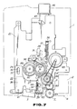
- the movable roll 7 is locked at a position in which it protrudes from the lower surface of the casing 1, in that, as shown in Figures 7 and 8, the slide plate 22 is locked in its slid position to bring the abutting projection 71 into abutment with the locking piece 50 of the slide plate 22 to control the reciprocating movement of the roll mounting plate which should occur against the bias of the fourth tension spring 66.
- the locking lever 75 to lock the thermal head 3 and the movable roll 7 has a rotary arm section 77 pivotally mounted at a fulcrum member 76 integral with the chassis base plate 21, and is pivotally mounted for rotation in a direction orthogonal to the surface of the chassis base plate 21.
- An engaging member 78 to engage the locking member 50 is provided at the foremost part of the rotary arm section 77. This engaging member 78 extends over an inclined cam surface 79 formed on one lateral side of the operating lever 45.
- the locking lever 75 is biased for rotation to bring the engaging member 78 into pressure contact with the inclined cam surface 79 by a fifth tension spring 82 installed between a spring retainer 80 integral with the chassis base plate 21 and another spring retainer 81 formed at one end of the engaging member 78.
- the locking lever 75 is turned against the bias of the fifth tension spring 82 in that the engaging member 78 is moved on the inclined cam surface 79 as a result of sliding of the operating lever 45.
- the locking lever 75 When the operating lever 45 is depressed for the first time so that the thermal head 3 protrudes through the opening 5, until the lever 45 is locked by the cam lever 59, the locking lever 75 is biased into rotation so that the engaging member 78 abuts on a lower horizontal surface section 79 a of the inclined cam surface 79, the locking lever 75 then locking the slide plate 22.
- the engaging member 78 is engaged with the locking member 50 of the slide plate 22 which is caused to slide by the operating lever 45 against the bias of the first torsion spring 37, the lever 75 also locking the roll mounting plate 62 which abuts the locking member 50. In this manner, the load acting on the roll mounting plate 62 via the movable roll 7 and the load acting on the slide plate 22 via the thermal head 3 at the time of recording of the picture information are prevented from being transmitted to the operating lever 45.
- a rotary encoder 83 constituting a readout amount sensor unit for detecting the amount of movement of the casing 1 to detect the amount of scanning of image information.
- the rotary encoder 83 is turned by the rotation of the movable roll 7, and is connected via a rubber belt 87 to a double gear 86 meshing via an intermediate gear 85 with a rolling gear 84 attached to one end of the supporting shaft 65 of the movable roll 7.
- the gears 85 and 86 are carried on the roll mounting plate 62 so as to reciprocate with the movable roll 7.
- the double gear 86 and the rotary encoder 83 are connected to each other by the extensible rubber belt 87, so that the connecting state of the rotary encoder is always maintained by elongation and contraction of the rubber belt 87 with the reciprocation of the movable roll 7.
- the movable roll 7 is maintained at all times in a state of pressure contact with the readout surface, under the bias of the fourth tension spring 74, as shown in Figure 6, so that the movement of the roll 7 simultaneously with that of the casing 1 is always maintained. In this manner, the movable roll 7 is able to turn the rotary encoder 83 accurately in an amount corresponding to the amount of actuation of the casing 1, so that the amount of the readout-scanning of the image information can be detected accurately.
- a tape supply reel shaft 88 and a tape take-up reel shaft 89 engaging respectively with the supply reel 10 and the take-up reel 11 of the tape cartridge 12 are mounted upright in the tape cartridge housing section 13 provided to one lateral side of the casing 1.
- the tape supply reel shaft 88 is supported by a supporting shaft 88 a mounted upright on the chassis base plate 21 under a prestress such that the reel shaft may be rotated under the application of a reel-out force to the ink tape 9 in order to prevent the ink tape 9 from being reeled out inadvertently due to free rotation of the supply roll 10 upon attachment of the tape cartridge 12.
- the tape take-up reel shaft 89 is supported on a support shaft 89 a mounted upright on an auxiliary substrate (not shown) provided to one lateral side of the chassis base plate 21, so as to protrude into the tape cartridge housing section 13 via a through-hole 96 in the chassis base plate 21
- the tape take-up reel shaft 89 is mounted for rotation and carries an end tape take-up gear 90.
- the reel shaft 89 is turned by the rotation of the end tape take-up gear 90 to cause rotation of the take-up reel 1 1 engaging with the tape take-up reel shaft 89 to take up the ink tape 9.
- the tape cartridge 12 is formed with a head fitting recess 12 a at its forward end, with the ink tape 9 being extended over the opened front side of the recess 12 a .
- the tape cartridge 12 is mounted within the tape cartridge housing section 13, with the supply reel 10 and the take-up reel 11 engaging respectively with the tape supply reel shaft 88 and with the tape take-up reel shaft 89, the heat transfer ink tape 9 drawn out of the tape cartridge 12 extends along a recording surface on the front side of the thermal head 3.
- the heat transfer ink tape 9 is reeled out gradually during recording of the image information to supply new transfer ink onto the recording surface of the thermal head 3.
- the ink tape 9 is reeled out by the tape take-up reel shaft 89 being rotated under the rotational force of the movable roll 7 which rolls on the object surface in pressure contact therewith when the input/output device is set to a recording mode.
- a tape reel-out gear 91 meshes between the tape take-up gear 90 and the double gear 86 supported on the roll mounting plate 62.
- the rotation of the movable roll 7 supported on the roll mounting plate 62 is transmitted via the tape reel-out gear 91 to the tape take-up gear 90 to cause the rotation of the take-up reel 11 of the tape cartridge 12 engaged with the tape take-up reel shaft 89, so as to reel out the heat transfer ink tape 9.
- tape reel-out gear 91 should be engaged between the tape take-up gear 90 and the double gear 86 only in the recording-scanning mode to reel out the ink tape 9, while the ink tape should not be reeled out in the readout-scanning mode.
- the tape take-up gear 90 and the double gear 86 are interconnected as shown in Figure 8 with the switching between the record-scanning mode and the read-out scanning mode.
- the tape reel-out gear 91 is mounted on the slide plate 22 which is slid in dependence upon the switching between the record-scanning mode and the readout-scanning mode.
- the slide plate 22 is slid so that the slide plate 22 protrudes via the opening 5 in the casing 1
- the tape reel-out gear 91 is moved with the slide plate 22 so as to be engaged between the tape take-up gear 90 and the double gear 86.
- the casing 1 is swept in one direction for recording the image information in one direction in the sequence in which the image information is read out.
- the tape reel-out gear 91 is mounted for rotation only in one direction shown by arrow G in Figures 1A and 7 in which the tape take-up gear 90 is rotated only in the direction of taking up the ink tape 9.
- a ratchet gear 92 mounted on the slide plate 22 meshes with a ratchet gear 91 a provided on the upper surface of the tape reel-out gear 91 so that the tape take-up gear 90 may be rotated only in one direction, as shown by the arrow 6 in Figures 1A and 7.
- tape reel-out gear 91 is rotated only in the clockwise direction shown by arrow D in Figure 7 or in the direction opposite to the arrow G in Figure 5 in which the slide plate 22 is slid against the bias of the first torsion spring 37.
- This tape take-up gear 90 is turned in this manner in the counterclockwise direction shown by arrow I in Figure 7 in which the force of the first torsion spring 37 to take up the heat transfer ink tape 9.
- the tape reel-out gear 91 is mounted in such as fashion that, when the gear 91 meshes with the tape take-up gear 90, a straight line interconnecting the centre of rotation of the tape take-up gear 90 is substantially at right angles to the slide direction of the slide plate 22.
- the image input/output device providing for both readout and recording of image information, can project the thermal head 3 at the opening 5 in the casing 1 only during recording of the image information to apply the ink tape 9 extending on the recording side of the thermal head 3 onto the object in order to effect recording.
- the thermal head 3 protruding through the opening 5 in the casing 1, it is impossible to have the heat transfer ink tape 9 extended on the recording side of the thermal head 3 to mount the tape cartridge 12 to the tape cartridge housing section 13, while it is also impossible to perform the operation of taking out the tape cartridge 12.
- the thermal head 3 is retracted into the inside of the casing 1 when the lid 14 which closes the tape cartridge housing section 13 is opened.
- the lid 14 is provided with an unlocking pin 92 to unlock the operating lever 45 from the cam lever 59 by acting on the lever 45 which, as a result of the first depressing operation, has been locked to the cam lever 59.
- this unlocking pin 93 is mounted on the end of a projection 94 provided on the inner lateral surface of the lid 14 and protruding into the inside of the tape cartridge housing section 13.
- a thrust member 95 is provided and positioned within a rotational trajectory of the unlocking pin 93, as shown in Figure 10A, so as to project into the inside of the tape cartridge 13, when the operating lever 45 is at the depressed position in which it is locked by the cam lever 59, as shown in Figure 8.
- This thrust member 95 is formed with a first inclined surface 95 a which is thrust by the unlocking pin 93 when the lid 14 is turned in the direction shown by arrow Y in Figure 10A in which the cover 14 uncovers the opening 13 a of the tape cartridge housing section 13, and a second inclined surface 95 b which is thrust by the unlocking pin 93 when the lid is turned in the direction of arrow Y2 shown in Figure 10A in which the lid closes the opening 13 a , these surfaces 95 a and 95 b together being chevron-shaped as shown.
- the first and second inclined surfaces 95 a and 95 b are of such a length that, when these surfaces are thrust by the unlocking pin 93, the operating lever 45 is thrust by a value sufficient to unlock the operating lever 45 that has been locked to the unlocking lever 59. It is noted that, for preventing flexure of the lid 14 due to an excessive force being applied to thrust the thrust member 95, even when the portion of the lid 14 lying along the lower side of the casing 1 and spaced from the site of the unlocking pin 93 is manipulated for rotating the lid 14 in the opening direction, the first inclined surface 95 a has longer length and is at a lesser inclination than the second surface 95 b .
- the thermal head 3 With the unlocking of the slide plate 22, the thermal head 3 is retracted into the casing 1, as described above.
- the thermal head 3 protruding from the opening 5 in the casing 1 is necessarily retracted into the casing 1 by the operation of opening or closing the lid 14.
- the lid 14 is also provided with a window 97 in register with the supply reel 10 of the tape cartridge 12 in the tape cartridge housing section 13 to permit visual checking of the amount of the tape remaining.
- the operating lever 45 When the image input/output device described is used for read-out scanning of the image information, the operating lever 45 remains unactuated so that the thermal head 3 does not protrude from the opening 5.
- the casing 1 is held by a hand of the user and the lower surface of the casing 1 is pressed onto the surface of an object P carrying the desired picture or image information to thrust the readout reference surface 6 into pressure contact with the image information carrying surface.
- the casing 1 is then moved in the direction shown by the arrow X in Figure 11 to read out the desired image information.
- the movable roll 7 is now free to be reciprocated and allowed to roll on the image information carrying surface in pressure contact therewith and so as to follow occasional distortions on the surface.
- the rotary encoder 83 may be revolved in an amount accurately proportionate to the distance traversed by the casing 1 to permit the read-out amount to be detected reliably.
- the slide plate 22 to depress the operating lever 45 for the first time is slid against the bias of the first tension spring 37 to cause the thermal head 3 to protrude from the opening 5 and be locked in this protruded position, the movable roll 7 protruding from the lower side of the casing 1.
- the thermal head 3 and the movable roll 7 are pressed onto the object P, as shown in Figure 12.
- the casing 1 is moved in the direction shown by arrow X in Figure 11 in which the movable roll 7 is allowed to roll, the heat transfer ink tape 9 is reeled out on the record surface of the thermal head 3 for scanning, as the movable roll 7 is allowed to roll, so that the image information is recorded by the thermal head 3 on the recording substrate.
- the movable roll 7 protrudes and is secured in the protruded position, so that the reading reference surface 6 is floated over the object P, as shown in Figure 12 to reduce the sliding friction of the ink tape 9 travelling along the record surface of the thermal head 3 to ensure smooth running of the casing 1.
- the movable roll is supported reciprocably on the side in which the read-out opening is formed, so that, when the main body of the device is moved for scanning as it is thrust onto the image information read-out surface, the reference surface for the object which is formed on the perimeter of the read-out opening may be brought into sliding contact at all times with the image information read-out surface.
- the movable roll is turned in synchronism with the means provided on the main body-of the device for sensing the distance traversed by the device, as the roll is allowed to roll on the image information read-out surface without being affected by occasional distortions on the read-out surface.
- the travel guide section is also revolved when the main body of the input/output device is moved on the image information read-out opening for scanning, so that, even with the small-size image read-out device, the image information read-out surface can be positioned at all times within the field of depth of the image read-out section to enable read-out and scanning of the image information with good resolution and accurate detection of the read-out amount of the image information timed with the movement of the main body of the device, as well as to permit smooth scanning of the image information readout surface.
- the cylindrical movable and stationary rolls are mounted parallel to each other and in a direction normal to the movement direction of the main body of the device, so that the main body may be moved along a straight line for scanning.
- the recording head protrudes via the opening formed in the lower surface of the main body of the input/output device, upon actuation of the operating lever, and the movable roll is locked in the state in which it protrudes from the lower surface of the main body of the input/output device, in such a fashion that the load applied during the recording operation is supported only by the movable roll and the recording head.
- no excess load is applied to the operating lever for shifting the recording head via the opening in the casing, so that the operating lever may be protected from possible injury and the operational reliability of the hand scanner type image input/output device is increased.
- the locking operation of the locking means to lock the recording head previously projected via the opening in the main body of the device is released upon opening the lid, with the recording head being then retracted into the main body of the device by biasing means for biasing the recording head towards its original position, so that, when the opening of the tape housing section is opened, the recording tape is ready at all time to be mounted in position to provide for safe and positive attachment of the recording tape.
- the tape take-up reel shaft is rotated by rotational drive means in the tape take-up direction, and the recording tape previously drawn out of the main body of the device is taken up within the main body, so that the recording tape may be projected positively to prevent the object from being contaminated by the recording tape drawn out of the main body of the device.
Abstract
Description
- The invention relates to a hand scanning type image input/output device.
- By means of such a device picture information of a desired portion of an object, such as printed matter, can be read out and the read-out information recorded at a desired portion of a recording substrate, such as paper.
- Patent Specification US-A-3 541 248 discloses an image input/output device including a readout unit for optically reading out information on the surface of a manuscript, such as a book, by manual scanning, a printer for printing out optical signals from the readout unit, and a controller for controlling the readout unit and the printer. However, the device shown in Patent Specification US-A-3 541 248 is bulky in overall size and hence is not portable.
- Other manual scanning type image input/output devices have been proposed, for example, in Patent Specifications US-A-4 716 291 and US-A-4 611 246, according to which a main body of a device having enclosed therein readout means for reading out a desired image information from an object, such as printed matter, and record means for recording the read out image information on a recording substrate, such as paper, is moved manually to scan the object thereby to enable the readout of the desired image information and the recording of the read out image to be performed on one and the same device.
- This kind of image input/output device is so arranged that, after the desired image information is read out from the object, a recording head, such as a thermal head, is caused to project from the main body of the device at the time that the read-out image information is recorded on the object, this recording head causing a recording tape, such as an ink tape, to abut on a recording substrate for recording the image information.
- In order that the desired image information may be read with improved resolution in this kind of hand scanning image input/output device, it is necessary that the scanning be performed with the image readout surface of the object perpetually positioned within the depth of field of an optical system, such as a lens array, to form the desired picture information on a line sensor constituting read-out means enclosed in the main body of the device. However, if the hand scanner type image input device is to be of a small size so that it can be carried by one hand, only a small size optical system, such as a lens array, enclosed in the main body of the device, can be used, whereby the optical system has only a limited field of depth.
- Hence, this kind of image input device is so arranged that a readout reference surface positioned within the depth of field of the optical system is formed on the perimeter of an image information readout opening which is formed on the lower surface of the main body of the device so as to be confronted by the readout means, this readout reference surface being contacted tightly with the image information readout surface during scanning so that scanning may be performed with the image information readout surface positioned within the extremely small field of depth of the optical system.
- Also, since the above described hand scanner type image input/output device can be moved freely on the object for scanning to read out the desired image information, there is provided an image information readout sensor system for sensing the amount of the read-out image information in dependence upon the distance by which the device has been moved. This sensor unit includes a roll provided on the surface of the main body of the device which is in contact with the object and a rotary encoder driven into rotation on the basis of the rotation of the roll to detect the read-out amount of the image information.
- However, in the above described image input device, when the roll is provided on the surface of the main body of the device in contact with the object, the readout reference surface cannot be contacted tightly and accurately with the image information readout surface, so that the image information readout surface can no longer be positioned within the field of depth of the optical system and hence the readout operation of the image information with high resolution cannot be realized.
- Also, should the roll remain stationary within the main body of the device, it may float due to, for example, distortion of the image information readout surface, so that the rotary encoder cannot revolve in synchronism with the movement of the device and hence the read-out amount of the image information cannot be detected accurately.
- According to one aspect of the invention, there is provided a hand scanner type image input/output device comprising a main body to be moved over and thereby to scan an object and having enclosed therein a read-out scanning section to readout and scan information recorded on the object, the information being entered via a read-out opening formed in a surface facing the object, the main body including a mounting reference surface with respect to the object at the perimeter of the read-out opening,
a movable roll reciprocably supported on the surface in which the read-out opening is formed, the movable roll being rotated in synchronism with means to detect the amount of movement of the main body, and
a travel guide section rotatably mounted on the main body. - According to another aspect of the invention, there is provided a hand scanner type image input/output device comprising a main body to be moved on and scan an object and having enclosed therein a read-out/scanning section to read out and scan information recorded on a desired portion of the object, the information being entered via a read-out opening formed in a surface facing the object, the main body including a mounting reference plane with respect to the object at the perimeter of the read-out opening,
a movable roll reciprocably supported on the surface in which the read-out opening is formed, the movable roll being rotated in synchronism with means for detecting the amount of movement of the main body,
means to reciprocate a recording head with respect to the main body, the recording head being made to project from or be retracted into an opening provided in the surface of the main body in which the read-out opening is formed,
a lid provided on the main body to close or open a tape housing section accommodating a recording tape provided in the main body, means to bias the recording head in the returning direction, means to lock the recording head projecting from the opening in the projected position, and
unlocking means to release locking of the locking means in response to the lid opening operation. - According to a still further aspect of the invention, there is provided a head scanner type image input/output device comprising a main body to be moved on and scan an object and having enclosed therein a read-out/scanning section to read out and scan information recorded on a desired portion of the object, the information being entered via a read-out opening formed on a surface facing the object, the main body including a mounting reference plane with respect to the object on the perimeter of the read-out opening,
a movable roll reciprocably supported on the surface in which the read-out opening is formed, the movable roll being rotated in synchronism with means to detect the amount of movement of the main body,
means to reciprocate a recording head with respect to the main body, the recording head being made to project from or be retracted into an opening provided in the surface of the main body in which the read-out opening is formed,
means to bias the reciprocating means in a return direction, tape take-up means to take up a recording tape provided in the main body, and
means to rotate the tape take-up means at the time of returning of the reciprocating means in a direction of taking up the recording tape provided in the main body. - In such a hand scanning type image input/output device wherein, even if an image readout device should be of a small size, the image information readout surface may be positioned at all times within the field of depth of the image readout section to enable the image information to be read out and scanned with good resolution and to enable the read-out amount of the image information to be detected precisely in synchronism with the amount of movement of the device to provide for smooth scanning of the input device on the image information readout surface.
- When the head for recording the image information is retracted into the main body of the device to enable reading out of the image information, the recording tape drawn out of the main body of the device by the recording head can be drawn into a tape cartridge within the main body of the device to protect the recording tape to prevent the object from being contaminated by the drawn out recording tape.
- When the lid to open or close an opening in the tape housing section is opened, the recording head is necessarily drawn into the main body of the device to enable the recording tape to be attached to and detached from the tape housing section.
- The invention is diagrammatically illustrated by way of example in the accompanying drawings, in which:-
- Figure 1A is a perspective view showing internal components of a hand scanning type image input/out device according to the invention, with the device being seen from one side of a chassis base plate;
- Figure 1B is a perspective view showing internal components of the hand scanning type image input/output device of Figure 1A, with the device being seen from the other side of the chassis base plate;
- Figure 2 is a diagrammatic perspective view showing one side of the image input/output device shown in Figures 1A and lB;
- Figure 3 is a diagrammatic perspective view showing the other side of a tape cartridge housing section of the image input/output device shown in Figures 1 and 2;
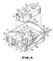
- Figure 4 is a diagrammatic perspective view showing the inside of the tape cartridge housing section of the image input/output device of Figure 3;
- Figure 5 is a plan view showing one side of chassis base plate is an image information readout state and showing internal components of a hand scanning type image input/output device according to the invention;
- Figure 6 is a plan view showing the other side of the chassis base plate in the state of Figure 5;
- Figure 7 is a plan view showing one side of the chassis base plate in an image information recording state.
- Figure 8 is a plan view showing the other side of the chassis base plate;
- Figure 9 is a perspective view showing a mounted state of a slide plate and a head mounting plate;
- Figures 10A and 10B are side views showing the relation between an unlocking pin and a plate thrusting piece, Figure 10A showing the state of the unlocking operation and Figure 10B showing the unlocking state;
- Figure 11 is a diagrammatic side view showing an image information reading state; and
- Figure 12 is a diagrammatic side view showing an image information recording state.
- Referring to the drawings, and firstly to Figures 2 and 3, a hand scanner type picture input/output device has a flat nearly rectangular casing 1 constituting a main body of the device that can be held with one hand. In the casing 1, there are enclosed an image
information reading section 2 constituting means for reading picture information of a desired portion of an object, such as book or like printed matter, and athermal head 3 constituting means for recording the picture information read in thereading section 2 on a recording substrate, such as paper. As shown in Figure 3, thereading section 2 has its information reading surface confronting areading opening 4 formed at one end on a lower surface of the casing 1 which can slide on the object during reading and scanning of the desired picture information. Thethermal head 3 is mounted so as to project from or be retracted into anopening 5 formed at the middle of the lower surface of the casing 1. - Between the
reading openings thermal head 3, there is provided amovable roller 7 that may be advanced or retracted during reading-scanning of the picture information to bring areading reference surface 6 formed at the perimeter of the reading opening 4 into sliding contact with the recording substrate and that may be locked during recording-scanning of the picture information at a position at which it protrudes from thereading reference surface 6. - At the other end of the lower surface of the casing 1, there is mounted a
guide roll 8 to guide the casing 1 during reading-scanning of picture information and recording-scanning of picture information so that the casing 1 may travel smoothly on the object and the recording substrate. Theguide roll 8 is formed of an elastic material, such as rubber, and mounted on an axle 8a lying orthogonally to the direction of movement of the casing 1 scanned during the reading or recording of the picture information, or the direction shown by arrow A in Figure 2. - On one lateral side of the casing 1, there is provided, as shown in Figure 4, a tape
cartridge housing section 13 for housing atape cartridge 12 wound between a take-up reel 11 and asupply reel 10 which can supply a heattransfer ink tape 9 which is a recording tape to be thermally transferred by the heatsensitive head 3. An opening 13a of the tapecartridge housing section 13 can be exposed or can be closed by alid 14 hingeably mounted on the casing 1. - The picture information on a desired portion of an object can be read by the image
information reading section 2 with the heatsensitive head 3 being retracted into theopening 5 so as not to protrude therefrom and with the casing 1 held manually so that thereading reference surface 6 on the lower side of the casing 1 slides over the reading surface of the object to scan the desired picture information. - For recording the thus read picture information on the desired portion of the recording substrate, the heat
sensitive head 3 protrudes out of theopening 5 and themovable roll 7 is locked at a position at which it protrudes from thereading reference surface 6. The casing 1 is held manually and both thehead 3 and theroller 7 are pressed onto the object to scan the desired object with the recording substrate to melt the transfer ink on the heattransfer ink tape 9 extending on the recording surface of the headsensitive head 3 to transfer and record the image information on the recording substrate. - The detailed structure of the hand scanner type image input/output device for reading and recording the picture information is explained hereafter in detail.
- Referring to Figure 6, the image
information reading section 2 of the hand scanner type picture input/output device includes areading head 17 composed of aline sensor 15 and alens array 16 which can form an image of the read picture on a light receiving surface 15a of theline sensor 15, and alight source 18 to irradiate the picture to be read on the object. Theline sensor 15 of thereading head 17 is formed by photo-elective conversion elements, such as CCD, while thelens array 16 is formed as a rod lens array composed of a plurality of distributed refractive index type pillar-shaped lenses of 1 to 2 mm diameter arranged in the shape of a flat plate. Thelight source 18 is formed by an array of light emitting diodes. - The
reading head 17 is mounted in the interior of the casing 1 in such a manner that an image information input side on one end face of thelens array 16 confronts thereading opening 4 on the lower side of the casing 1 so that an image of the picture information facing thereading opening 4 is formed on the light receiving surface 15a of theline sensor 15. In order to provide for satisfactory dissolution of the picture information and correct image formation on the light receiving surface 15a of theline sensor 15 thereading reference surface 6 on the perimeter of thereading opening 4 which slides on the object during reading-scanning of the image information can be positioned within the depth of field of thelens array 16. Thelight source 18 is positioned with its light emitting surface facing one side of the read-out opening 4 to irradiate the picture information facing thereading opening 4. Reading-scanning of the picture information by the pictureinformation reading section 2 is controlled by pressing a reading-scanning control button 19 provided on the upper surface of the casing 1. - The heat sensitive or
thermal head 3 employed in this image input/output device is so constructed and arranged that the current is supplied selectively to a plurality of heating elements to evolve heat to melt the transfer ink on the heattransfer ink tape 9 to transfer and record the image on the recording substrate. - As shown in Figures 1A and 9, this heat sensitive
thermal head 3 is mounted in position via ahead mounting plate 23 supported on aslide plate 22 slidably mounted on one lateral side of achassis base plate 21 provided within the casing 1. As theslide plate 21 is slid, thehead 3 may emerge from or be retracted into theopening 5 provided on the lower surface of the casing 1. - Referring to Figure 5, the
slide plate 22 is formed by a connectingplate 24 on both ends of which a first slideguide arm section 25 and a second slideguide arm section 26 are formed parallel to each other. Substantially at the middle of theslide plate 22 is formed a cut-out 27 to which faces a gear for rotating a take-up reel shaft attached to the end of the take-up reel shaft projectedly mounted within the tapecartridge housing section 13 as later described. Theslide plate 22 is slidably mounted on one lateral side of thechassis base plate 21 by engaging and supporting slide guide pins 31, 32 and 33 implanted on thechassis base plate 21 in a pair ofslide guide openings guide arm section 25 and aslide guide opening 30 formed in the second slideguide arm section 26, respectively. Theslide plate 22 is biased to slide towards the upper side of the casing 1 in the direction of arrow mark B in Figure 5 by atorsion spring 37 installed under tension between aspring retainer 35 formed upright on one side of the slideguide arm section 25 and aspring retainer 36 formed integrally with thechassis base plate 21. - Referring to Figures 5 and 9, the
head mounting plate 23 is an L-shaped plate formed with ahead mounting section 39 lying under the lower edge of a mounting and supportingsection 38 by which theplate 23 is mounted on theslide plate 22. As shown in Figure 1B, the heatsensitive type head 3 is mounted on the lower surface of thehead mounting section 39 and is oscillatably supported with a supportingshaft 40 by thehead mounting section 39 so that, when an object is scanned, the recording surface will slide on the record surface of the object. Thehead mounting section 39 is formed on the head attachment side thereof with anoscillation control projection 39a to control the amount of oscillation of the heatsensitive head 3. Thehead mounting plate 23 fitted in this manner with the heatsensitive head 3 is mounted with the mounting supportingsection 38 superimposed on the connectingplate 24 of theslide plate 22. As shown in Figures 5 and 9, thehead mounting plate 23 is mounted on theslide plate 22 by having one corner on the lower side of the mounting and supportingsection 38 supported by a supportingshaft 41 and by having aspring retainer 42 on one upper side opposite to theshaft 41 confronted by thecutout 27 in theslide plate 22 so as to be engaged with the upper edge of the connectingplate 24. Thehead mounting plate 23, mounted in this manner on theslide plate 22, is urged to be turned about the supportingshaft 41 in a direction shown by arrow C in Figures 5 and 9 in which the recording surface is caused to project from theopening 5 by asecond torsion spring 44 installed between thespring retainer 42 and aspring retainer 43 formed at the lower side of theslide plate 22. By biasing thehead mounting plate 23 into rotation in this manner, the heatsensitive head 3 is thrust against the record surface of the object when performing recording-scanning of the read-out image information. - The heat
sensitive head 3 thus supported by theslide plate 22 may be actuated, as shown in Figures 6 and 8, so as to emerge from or be retracted into theopening 5 in the casing 1, as theslide plate 22 is advanced and retracted by a read/recordchangeover operating lever 45 slidably supported on thechassis base plate 21. The operatinglever 45 is formed by moulding synthetic resin and has anoperating button 46 fitted on its upper side. This button protrudes through anopening 47 formed on the upper surface of the casing 1, as shown in Figure 2. Referring to Figure 1B, anoperating section 48 formed at the lower mid portion is caused to abut on a lockingmember 50 projecting towards the other side of thechassis base plate 21 via anopening 49 in thechassis base plate 21. Themember 50 is formed at the upper end of the first slideguide arm section 25 of theslide plate 22. A spring retainingslide guide pin 53 and a cam lever operatingslide guide pin 54 are engaged in a pair ofslide guide openings 51 each having its longer axis lying in the longitudinal direction. The operatinglever 45 is slidably supported on the other lateral side of thechassis plate 21 to slide vertically with respect to thechassis base plate 21. The operatinglever 45 is biased to slide in the direction of arrow D in Figure 6, that is, towards the upper side of the casing 1 and away from the lockingmember 50 of theslide plate 22, by means of athird tension spring 57 installed between aspring retainer 56 formed at the end of anupright wall 55 which is positioned at the tapecartridge housing section 13 when thelever 45 is attached to thechassis base plate 21 and a spring retainer at the foremost part of the spring retainingslide guide pin 53. - To the mid portion of the operating
lever 45 is mounted acam lever 59 having acam groove 58. Thecam lever 59 is engaged with the end of theslide guide pin 54 to lock the operatinglever 45 in a predetermined depressed position when thelever 45 is depressed for the first time against the bias of thethird torsion spring 57 as shown in Figure 8, with the locking state being released when thelever 45 is depressed a second time. Hence thelever 45 acts as a so-called push-pull type operating lever. - The
cam lever 59 has its base portion fulcrummed by a supportingshaft 60 provided upright at the mid portion of the operatinglever 45, and is biased to be turned in the direction of arrow E in Figure 6 so that the end part of the cam lever is pressed onto the foremost part of theslide guide pin 54 by atorsion coil spring 61 wound about the supportingshaft 60, in such a manner that thecam groove 58 is not disengaged from theslide guide pin 54 during depression of the operatinglever 45. - By sliding the
slide plate 22 against the bias of thesecond tension spring 44 by the first depressing operation of the operatinglever 45, as shown in Figure 8, thethermal head 3 mounted by thehead mounting plate 23 is caused to protrude out of theopening 5 in the casing 1. At this time, theslide plate 22 is locked by a locking lever, as described later, in such a fashion that the depression force acting on theslide plate 22 via thethermal head 3 during recording is not applied directly to the operatinglever 45. - When the second depression operation is performed from the state of Figure 8 in which the
cam lever 59 is engaged with theslide guide pin 54 to lock the operatinglever 45 in the predetermined depressed position, thecam lever 59 is disengaged from theslide guide pin 54, the operatinglever 45 being returned by the action of thethird tension spring 59 as shown in Figure 6 to unlock the lock lever. The slide plate is slid by thesecond tension spring 44 to withdraw thethermal head 3 via theopening 3 into the casing 1. - The
movable roll 7 can be reciprocated to bring thereadout reference surface 6 formed on the perimeter of thereadout opening 4 into sliding contact with the object during the readout-scanning of the picture information, or cause theroll 7 to project from thereadout reference surface 6 during recording-scanning of the picture information. As shown in Figures 1B and 6, themovable roll 7 is reciprocably mounted to the lower surface of the casing 1 by aroll mounting plate 62 provided reciprocably on thechassis base plate 21. - The
roll mounting plate 62 has aslide supporting section 63 slidably supported on thechassis base plate 21 and a U-shapedroll mounting section 64 formed at the end of theslide supporting section 63. Themovable roll 7 includes an elasticcylindrical rubber element 66 fitted to a supportingshaft 65. Thismovable roll 7 is supported by the supportingshaft 65 at the end of theroll mounting section 64. Theroll mounting plate 62 is mounted reciprocably and vertically with respect to thechassis base plate 21 with aslide guide projection 68 integral with thechassis base plate 21 engaging in aslide guide opening 67 having its long axis extending longitudinally and an uprightslide guide pin 70 of thechassis base plate 21 engaging in an elongate in-shapedslide guide groove 69. Anabutment projection 71 formed on the base side of theslide supporting section 63 confronts the lockingmember 50 formed on theslide plate 22 to project on the other lateral side of thechassis base plate 21. Theroll mounting plate 62 is biased to be moved in the direction of arrow F in Figure 6, so that themovable end roll 7 partially protrudes beyond the read-outreference surface 6 on the lower surface of the casing 1, by afourth tension spring 74 installed between aspring retainer 72 integral with theroll mounting plate 62 and anotherspring retainer 73 integral with thechassis base plate 21. - The
moveable roll 7 biased to be moved in this manner by thefourth tension spring 74 can be reciprocated to bringreadout reference surface 6 on the lower surface of the casing 1 into sliding contact with the readout surface of the object during readout scanning of the picture information, while being moved in rolling pressure contact with the readout surface a distance corresponding to the amount of movement of the casing 1 under the bias of thefourth tension spring 74. - During recording of the picture information, as shown in Figure 8, the
movable roll 7 is locked against a reciprocating movement at a position to which it is moved under the bias of thefourth tension spring 74 and at which it projects beyond the lower surface of the casing 1, as described later. - During recording of picture information, the
thermal head 3 protruding via theopening 5 in the casing 1 for scanning is locked at a position at which it protrudes from theopening 5, by thelock member 50 of theslide plate 22 being locked by a lockinglever 75 provided on thechassis base plate 21 and by the slide plate being locked at a position at which it is slid under the bias of thefirst tension spring 37, as shown in Figure 8. Themovable roll 7 is locked at a position in which it protrudes from the lower surface of the casing 1, in that, as shown in Figures 7 and 8, theslide plate 22 is locked in its slid position to bring the abuttingprojection 71 into abutment with the lockingpiece 50 of theslide plate 22 to control the reciprocating movement of the roll mounting plate which should occur against the bias of thefourth tension spring 66. - Referring to Figure 1B, the locking
lever 75 to lock thethermal head 3 and themovable roll 7 has arotary arm section 77 pivotally mounted at afulcrum member 76 integral with thechassis base plate 21, and is pivotally mounted for rotation in a direction orthogonal to the surface of thechassis base plate 21. An engagingmember 78 to engage the lockingmember 50 is provided at the foremost part of therotary arm section 77. This engagingmember 78 extends over aninclined cam surface 79 formed on one lateral side of the operatinglever 45. The lockinglever 75 is biased for rotation to bring the engagingmember 78 into pressure contact with theinclined cam surface 79 by afifth tension spring 82 installed between aspring retainer 80 integral with thechassis base plate 21 and anotherspring retainer 81 formed at one end of the engagingmember 78. The lockinglever 75 is turned against the bias of thefifth tension spring 82 in that the engagingmember 78 is moved on theinclined cam surface 79 as a result of sliding of the operatinglever 45. - When the operating
lever 45 is depressed for the first time so that thethermal head 3 protrudes through theopening 5, until thelever 45 is locked by thecam lever 59, the lockinglever 75 is biased into rotation so that the engagingmember 78 abuts on a lower horizontal surface section 79a of theinclined cam surface 79, the lockinglever 75 then locking theslide plate 22. The engagingmember 78 is engaged with the lockingmember 50 of theslide plate 22 which is caused to slide by the operatinglever 45 against the bias of thefirst torsion spring 37, thelever 75 also locking theroll mounting plate 62 which abuts the lockingmember 50. In this manner, the load acting on theroll mounting plate 62 via themovable roll 7 and the load acting on theslide plate 22 via thethermal head 3 at the time of recording of the picture information are prevented from being transmitted to the operatinglever 45. - When the operating
lever 45 is unlocked with respect to thecam lever 59 by the second depression operation and slid by thethird tension spring 57 in the turning direction, the engagingmember 78 is thrust from aninclined surface section 79b of the linedcam surface 79 onto an upperhorizontal surface section 79c, the lockinglever 75 being turned against the bias of thefifth tension spring 82 to release the engagement of the engaging member with the lockingmember 50 and the locking of theslide plate 22 with theroll mounting plate 62. By this unlocking, theslide plate 22 is slid by thefirst tension spring 37 in a direction shown by arrow B in Figure 5 to retract thethermal head 3 into the casing 1. Theroll mounting plate 62 is now free to be reciprocated against the bias of thefourth tension spring 74, as shown in Figure 6. The image input/output device is now enabled to read the image information. - Within the casing 1, there is mounted via the chassis base plate 21 a
rotary encoder 83 constituting a readout amount sensor unit for detecting the amount of movement of the casing 1 to detect the amount of scanning of image information. As shown in Figures 1A and 5, therotary encoder 83 is turned by the rotation of themovable roll 7, and is connected via arubber belt 87 to adouble gear 86 meshing via anintermediate gear 85 with a rollinggear 84 attached to one end of the supportingshaft 65 of themovable roll 7. Thegears roll mounting plate 62 so as to reciprocate with themovable roll 7. However, thedouble gear 86 and therotary encoder 83 are connected to each other by theextensible rubber belt 87, so that the connecting state of the rotary encoder is always maintained by elongation and contraction of therubber belt 87 with the reciprocation of themovable roll 7. - During reading out of image information, the
movable roll 7 is maintained at all times in a state of pressure contact with the readout surface, under the bias of thefourth tension spring 74, as shown in Figure 6, so that the movement of theroll 7 simultaneously with that of the casing 1 is always maintained. In this manner, themovable roll 7 is able to turn therotary encoder 83 accurately in an amount corresponding to the amount of actuation of the casing 1, so that the amount of the readout-scanning of the image information can be detected accurately. - Referring to Figure 4, a tape
supply reel shaft 88 and a tape take-upreel shaft 89 engaging respectively with thesupply reel 10 and the take-up reel 11 of thetape cartridge 12 are mounted upright in the tapecartridge housing section 13 provided to one lateral side of the casing 1. The tapesupply reel shaft 88 is supported by a supportingshaft 88a mounted upright on thechassis base plate 21 under a prestress such that the reel shaft may be rotated under the application of a reel-out force to theink tape 9 in order to prevent theink tape 9 from being reeled out inadvertently due to free rotation of thesupply roll 10 upon attachment of thetape cartridge 12. - On the other hand, the tape take-up
reel shaft 89 is supported on asupport shaft 89a mounted upright on an auxiliary substrate (not shown) provided to one lateral side of thechassis base plate 21, so as to protrude into the tapecartridge housing section 13 via a through-hole 96 in thechassis base plate 21 The tape take-upreel shaft 89 is mounted for rotation and carries an end tape take-up gear 90. Thereel shaft 89 is turned by the rotation of the end tape take-up gear 90 to cause rotation of the take-up reel 1 1 engaging with the tape take-upreel shaft 89 to take up theink tape 9. - Referring to Figure 4, the
tape cartridge 12 is formed with a head fitting recess 12a at its forward end, with theink tape 9 being extended over the opened front side of the recess 12a. When thetape cartridge 12 is mounted within the tapecartridge housing section 13, with thesupply reel 10 and the take-up reel 11 engaging respectively with the tapesupply reel shaft 88 and with the tape take-upreel shaft 89, the heattransfer ink tape 9 drawn out of thetape cartridge 12 extends along a recording surface on the front side of thethermal head 3. - The heat
transfer ink tape 9 is reeled out gradually during recording of the image information to supply new transfer ink onto the recording surface of thethermal head 3. Theink tape 9 is reeled out by the tape take-upreel shaft 89 being rotated under the rotational force of themovable roll 7 which rolls on the object surface in pressure contact therewith when the input/output device is set to a recording mode. - More specifically, when the operating
lever 45 is depressed for the first time to enable recording of image information, with thethermal head 33 protruding from theopening 5 in the casing 1, a tape reel-out gear 91 meshes between the tape take-up gear 90 and thedouble gear 86 supported on theroll mounting plate 62. The rotation of themovable roll 7 supported on theroll mounting plate 62 is transmitted via the tape reel-out gear 91 to the tape take-up gear 90 to cause the rotation of the take-up reel 11 of thetape cartridge 12 engaged with the tape take-upreel shaft 89, so as to reel out the heattransfer ink tape 9. - It will be noted that the tape reel-
out gear 91 should be engaged between the tape take-up gear 90 and thedouble gear 86 only in the recording-scanning mode to reel out theink tape 9, while the ink tape should not be reeled out in the readout-scanning mode. To this end, the tape take-up gear 90 and thedouble gear 86 are interconnected as shown in Figure 8 with the switching between the record-scanning mode and the read-out scanning mode. - The tape reel-
out gear 91 is mounted on theslide plate 22 which is slid in dependence upon the switching between the record-scanning mode and the readout-scanning mode. When theslide plate 22 is slid so that theslide plate 22 protrudes via theopening 5 in the casing 1, the tape reel-out gear 91 is moved with theslide plate 22 so as to be engaged between the tape take-up gear 90 and thedouble gear 86. - The casing 1 is swept in one direction for recording the image information in one direction in the sequence in which the image information is read out. For supplying a new portion of the heat
transfer ink tape 9 at all times to the recording surface of thethermal head 3 and for preventing slackening of the ink tape during reeling, the tape reel-out gear 91 is mounted for rotation only in one direction shown by arrow G in Figures 1A and 7 in which the tape take-up gear 90 is rotated only in the direction of taking up theink tape 9. More specifically, aratchet gear 92 mounted on theslide plate 22 meshes with a ratchet gear 91a provided on the upper surface of the tape reel-out gear 91 so that the tape take-up gear 90 may be rotated only in one direction, as shown by thearrow 6 in Figures 1A and 7. - It should be noted that the tape reel-
out gear 91 is rotated only in the clockwise direction shown by arrow D in Figure 7 or in the direction opposite to the arrow G in Figure 5 in which theslide plate 22 is slid against the bias of thefirst torsion spring 37. This tape take-up gear 90 is turned in this manner in the counterclockwise direction shown by arrow I in Figure 7 in which the force of thefirst torsion spring 37 to take up the heattransfer ink tape 9. Thus, when theslide plate 22 is slid in the direction of retracting thethermal head 3 and the tape reel-out gear 91 clears the tape take-up gear 90, this tape reel-out gear 91 causes rotation of the tape take-up gear 90 in the tape take-up direction. Inasmuch as the take-up operation of the take-up reel 11 is performed in synchronism with the retraction of thethermal head 3, that portion of theink tape 9 which has been reeled out in excess by the projection of thethermal head 3 from the lower surface of the casing 1 will be taken up in thetape cartridge 12 to prevent the slackening of the ink tape outside thetape cartridge 12. - To ensure rotation of the tape take-
up gear 90 during retraction of theslide plate 22, the tape reel-out gear 91 is mounted in such as fashion that, when thegear 91 meshes with the tape take-up gear 90, a straight line interconnecting the centre of rotation of the tape take-up gear 90 is substantially at right angles to the slide direction of theslide plate 22. - The image input/output device, providing for both readout and recording of image information, can project the
thermal head 3 at theopening 5 in the casing 1 only during recording of the image information to apply theink tape 9 extending on the recording side of thethermal head 3 onto the object in order to effect recording. Thus, with thethermal head 3 protruding through theopening 5 in the casing 1, it is impossible to have the heattransfer ink tape 9 extended on the recording side of thethermal head 3 to mount thetape cartridge 12 to the tapecartridge housing section 13, while it is also impossible to perform the operation of taking out thetape cartridge 12. - For this reason, the
thermal head 3 is retracted into the inside of the casing 1 when thelid 14 which closes the tapecartridge housing section 13 is opened. - Thus the
lid 14 is provided with an unlockingpin 92 to unlock the operatinglever 45 from thecam lever 59 by acting on thelever 45 which, as a result of the first depressing operation, has been locked to thecam lever 59. Referring to Figure 4, this unlockingpin 93 is mounted on the end of aprojection 94 provided on the inner lateral surface of thelid 14 and protruding into the inside of the tapecartridge housing section 13. On one side of theupright wall 55 of the operatinglever 45, athrust member 95 is provided and positioned within a rotational trajectory of the unlockingpin 93, as shown in Figure 10A, so as to project into the inside of thetape cartridge 13, when the operatinglever 45 is at the depressed position in which it is locked by thecam lever 59, as shown in Figure 8. Thisthrust member 95 is formed with a firstinclined surface 95a which is thrust by the unlockingpin 93 when thelid 14 is turned in the direction shown by arrow Y in Figure 10A in which thecover 14 uncovers the opening 13a of the tapecartridge housing section 13, and a secondinclined surface 95b which is thrust by the unlockingpin 93 when the lid is turned in the direction of arrow Y₂ shown in Figure 10A in which the lid closes the opening 13a, thesesurfaces inclined surfaces pin 93, the operatinglever 45 is thrust by a value sufficient to unlock the operatinglever 45 that has been locked to the unlockinglever 59. It is noted that, for preventing flexure of thelid 14 due to an excessive force being applied to thrust thethrust member 95, even when the portion of thelid 14 lying along the lower side of the casing 1 and spaced from the site of the unlockingpin 93 is manipulated for rotating thelid 14 in the opening direction, the firstinclined surface 95a has longer length and is at a lesser inclination than thesecond surface 95b. - It is assumed that, in the state in which the operating
lever 45 is depressed and locked by thecam lever 59, or in which thethermal head 3 protrudes from theopening 5 as shown in Figure 8, thelid 14 is opened or closed, as shown in Figure 10A. At this time, the unlockingpin 93 thrusts the firstinclined surface 95a or the secondinclined surface 95b of thethrust member 95, as shown in Figures 10A and 10B. At this time, the operatinglever 45 is depressed a second time against the bias of thethird torsion spring 57 to unlock the operating lever from thecam lever 59. The operatinglever 45 thus unlocked from thecam lever 59 is returned to its original position under the action of thethird tension spring 57 to act on the lockinglever 75 for unlocking theslide plate 22. With the unlocking of theslide plate 22, thethermal head 3 is retracted into the casing 1, as described above. Thus thethermal head 3 protruding from theopening 5 in the casing 1 is necessarily retracted into the casing 1 by the operation of opening or closing thelid 14. - When the operating
lever 45 is at its original position under the bias of thethird torsion spring 57, with the operatinglever 45 not being locked by thecam lever 59 and thethermal head 3 not protruding from theopening 5, thethrust member 95 is off the rotational trajectory ϑ of the lockingpin 93. - The
lid 14 is also provided with awindow 97 in register with thesupply reel 10 of thetape cartridge 12 in the tapecartridge housing section 13 to permit visual checking of the amount of the tape remaining. - When the image input/output device described is used for read-out scanning of the image information, the operating
lever 45 remains unactuated so that thethermal head 3 does not protrude from theopening 5. The casing 1 is held by a hand of the user and the lower surface of the casing 1 is pressed onto the surface of an object P carrying the desired picture or image information to thrust thereadout reference surface 6 into pressure contact with the image information carrying surface. The casing 1 is then moved in the direction shown by the arrow X in Figure 11 to read out the desired image information. - The
movable roll 7 is now free to be reciprocated and allowed to roll on the image information carrying surface in pressure contact therewith and so as to follow occasional distortions on the surface. In this manner, therotary encoder 83 may be revolved in an amount accurately proportionate to the distance traversed by the casing 1 to permit the read-out amount to be detected reliably. - When the image information thus read by the image input/output device is to be recorded, the
slide plate 22 to depress the operatinglever 45 for the first time is slid against the bias of thefirst tension spring 37 to cause thethermal head 3 to protrude from theopening 5 and be locked in this protruded position, themovable roll 7 protruding from the lower side of the casing 1. - In this state, the
thermal head 3 and themovable roll 7 are pressed onto the object P, as shown in Figure 12. When the casing 1 is moved in the direction shown by arrow X in Figure 11 in which themovable roll 7 is allowed to roll, the heattransfer ink tape 9 is reeled out on the record surface of thethermal head 3 for scanning, as themovable roll 7 is allowed to roll, so that the image information is recorded by thethermal head 3 on the recording substrate. - During recording of the image information, the
movable roll 7 protrudes and is secured in the protruded position, so that the readingreference surface 6 is floated over the object P, as shown in Figure 12 to reduce the sliding friction of theink tape 9 travelling along the record surface of thethermal head 3 to ensure smooth running of the casing 1. - The movable roll is supported reciprocably on the side in which the read-out opening is formed, so that, when the main body of the device is moved for scanning as it is thrust onto the image information read-out surface, the reference surface for the object which is formed on the perimeter of the read-out opening may be brought into sliding contact at all times with the image information read-out surface. On the other hand, the movable roll is turned in synchronism with the means provided on the main body-of the device for sensing the distance traversed by the device, as the roll is allowed to roll on the image information read-out surface without being affected by occasional distortions on the read-out surface.
- In addition, the travel guide section is also revolved when the main body of the input/output device is moved on the image information read-out opening for scanning, so that, even with the small-size image read-out device, the image information read-out surface can be positioned at all times within the field of depth of the image read-out section to enable read-out and scanning of the image information with good resolution and accurate detection of the read-out amount of the image information timed with the movement of the main body of the device, as well as to permit smooth scanning of the image information readout surface.
- In the above described embodiment, the cylindrical movable and stationary rolls are mounted parallel to each other and in a direction normal to the movement direction of the main body of the device, so that the main body may be moved along a straight line for scanning.
- The recording head protrudes via the opening formed in the lower surface of the main body of the input/output device, upon actuation of the operating lever, and the movable roll is locked in the state in which it protrudes from the lower surface of the main body of the input/output device, in such a fashion that the load applied during the recording operation is supported only by the movable roll and the recording head. Hence, no excess load is applied to the operating lever for shifting the recording head via the opening in the casing, so that the operating lever may be protected from possible injury and the operational reliability of the hand scanner type image input/output device is increased.
- Also, the locking operation of the locking means to lock the recording head previously projected via the opening in the main body of the device is released upon opening the lid, with the recording head being then retracted into the main body of the device by biasing means for biasing the recording head towards its original position, so that, when the opening of the tape housing section is opened, the recording tape is ready at all time to be mounted in position to provide for safe and positive attachment of the recording tape.
- In addition, when the slide plate is actuated with the recording head in the projected state and the operation of restoration is performed by bias means in a direction in which the recording head is retracted into the inside of the main body of the device, the tape take-up reel shaft is rotated by rotational drive means in the tape take-up direction, and the recording tape previously drawn out of the main body of the device is taken up within the main body, so that the recording tape may be projected positively to prevent the object from being contaminated by the recording tape drawn out of the main body of the device.
Claims (24)
a movable roll (7) reciprocably supported on the surface in which the read-out opening (2) is formed, the movable roll (7) being rotated in synchronism with means (83) to detect the amount of movement of the main body (1), and
a travel guide section (8) rotatably mounted on the main body (1).
a movable roll (7) reciprocably supported on the surface in which the read-out opening (4) is formed, the movable roll (7) being rotated in synchronism with means (83) for detecting the amount of movement of the main body (1),
means (22, 46) to reciprocate a recording head (3) with respect to the main body, the recording head (3) being made to project from or be retracted into an opening (5) provided in the surface of the main body in which the read-out opening (4) is formed,
a lid (14) provided on the main body to close or open a tape housing section accommodating a recording tape provided in the main body, means to bias the recording head in the returning direction,
means (59) to lock the recording head projecting from the opening in the projected position, and
unlocking means to release locking of the locking means in response to the lid opening operation.
a movable roll (7) reciprocably supported on the surface in which the read-out opening (4) is formed, the movable roll being rotated in synchronism with means (83) to detect the amount of movement of the main body,
means (22, 46) to reciprocate a recording head (3) with respect to the main body, the recording head (3) being made to project from or be retracted into an opening (5) provided in the surface of the main body in which the read-out opening (4) is formed, means to bias the reciprocating means (22) in a return direction, tape take-up means (90) to take up a recording tape provided in the main body, and
means to rotate the tape take-up means (90) at the time of returning of the reciprocating means (22) in a direction of taking up the recording tape provided in the main body.
Applications Claiming Priority (2)
| Application Number | Priority Date | Filing Date | Title |
|---|---|---|---|
| JP63048076A JPH01222564A (en) | 1988-03-01 | 1988-03-01 | Manual scanning type picture input/output device |
| JP48076/88 | 1988-03-01 |
Publications (2)
| Publication Number | Publication Date |
|---|---|
| EP0331451A1 true EP0331451A1 (en) | 1989-09-06 |
| EP0331451B1 EP0331451B1 (en) | 1993-09-22 |
Family
ID=12793251
Family Applications (1)
| Application Number | Title | Priority Date | Filing Date |
|---|---|---|---|
| EP89302011A Expired - Lifetime EP0331451B1 (en) | 1988-03-01 | 1989-02-28 | Hand scanner type image input/output device |
Country Status (5)
| Country | Link |
|---|---|
| US (1) | US4901164A (en) |
| EP (1) | EP0331451B1 (en) |
| JP (1) | JPH01222564A (en) |
| CA (1) | CA1324433C (en) |
| DE (1) | DE68909274T2 (en) |
Cited By (2)
| Publication number | Priority date | Publication date | Assignee | Title |
|---|---|---|---|---|
| EP0862516A1 (en) * | 1995-11-06 | 1998-09-09 | Howard H. Bobry | Hand-held sweep electronic printer with compensation for non-linear movement |
| EP0910508A1 (en) * | 1995-11-06 | 1999-04-28 | Howard H. Bobry | Hand-held electronic printer |
Families Citing this family (19)
| Publication number | Priority date | Publication date | Assignee | Title |
|---|---|---|---|---|
| US5227909A (en) * | 1991-09-30 | 1993-07-13 | Calcomp Inc. | Single coil digitizer-coupled image scanner |
| JP3397366B2 (en) * | 1993-03-19 | 2003-04-14 | キヤノン株式会社 | Imaging device |
| US5459588A (en) * | 1993-08-18 | 1995-10-17 | Logitech, Inc. | Apparatus and method for clutchless motor driven hand held scanner |
| JPH09118048A (en) * | 1995-10-25 | 1997-05-06 | Brother Ind Ltd | Manual printing apparatus |
| JPH09156162A (en) * | 1995-12-05 | 1997-06-17 | Brother Ind Ltd | Compact printing apparatus |
| US5595445A (en) * | 1995-12-27 | 1997-01-21 | Bobry; Howard H. | Hand-held optical scanner |
| JPH09254408A (en) * | 1996-03-22 | 1997-09-30 | Brother Ind Ltd | Manual printing apparatus |
| US5848849A (en) * | 1996-07-25 | 1998-12-15 | Brother Kogyo Kabushiki Kaisha | Manual printer |
| US5988900A (en) * | 1996-11-01 | 1999-11-23 | Bobry; Howard H. | Hand-held sweep electronic printer with compensation for non-linear movement |
| DE19716066C1 (en) * | 1997-04-17 | 1998-09-10 | Techkon Elektronik Gmbh | Manual measurement device for reflection measurement on printed sheets and test patterns |
| US5816718A (en) * | 1997-07-21 | 1998-10-06 | Zebra Technologies Corporation | Hand-held label printer applicator |
| JPH1166268A (en) * | 1997-08-13 | 1999-03-09 | Fujitsu Ltd | Image reader |
| JP2001069319A (en) * | 1999-08-25 | 2001-03-16 | Nec Corp | Handy type scanner |
| US20030076408A1 (en) * | 2001-10-18 | 2003-04-24 | Nokia Corporation | Method and handheld device for obtaining an image of an object by combining a plurality of images |
| SE527210C2 (en) * | 2002-03-11 | 2006-01-17 | Printdreams Europ Ab | Sensor and print head unit and method for a hand operated handwriting device |
| US7055743B2 (en) * | 2003-02-20 | 2006-06-06 | Hewlett-Packard Development Company, L.P. | End-of-travel focus shift in an optical image scanner |
| US20040163754A1 (en) * | 2003-02-22 | 2004-08-26 | Nowicki James W. | Reactivation of pre-applied adhesives by ultrasonic waves |
| US20050022686A1 (en) * | 2003-07-28 | 2005-02-03 | Dreampatch, Llc | Apparatus, method, and computer program product for animation pad transfer |
| JP6959343B2 (en) | 2017-01-09 | 2021-11-02 | ヘンケル・アクチェンゲゼルシャフト・ウント・コムパニー・コマンディットゲゼルシャフト・アウフ・アクチェンHenkel AG & Co. KGaA | Curable protective coating composition |
Citations (6)
| Publication number | Priority date | Publication date | Assignee | Title |
|---|---|---|---|---|
| US3541248A (en) * | 1967-09-29 | 1970-11-17 | Xerox Corp | Document abstractor with hand-held optical scanner with constant resolution scanning |
| DE3220016A1 (en) * | 1982-05-27 | 1983-12-01 | Dorner, Jörg, Dr.-Ing., 8000 München | DEVICE FOR PRODUCING AN OPTICAL OR ELECTRONICALLY OR MAGNETICALLY STORED IMAGE INFORMATION OF AN ESSENTIAL AREA |
| US4611246A (en) * | 1984-11-14 | 1986-09-09 | Casio Computer Co., Ltd. | Handy reader/printer apparatus |
| US4639790A (en) * | 1983-12-19 | 1987-01-27 | Sony Corporation | Image input apparatus |
| US4716291A (en) * | 1984-05-16 | 1987-12-29 | Matsushita Electric Industrial Co., Ltd. | Copying machine |
| US4717965A (en) * | 1985-01-17 | 1988-01-05 | Ricoh Company, Ltd. | Portable image forming device |
Family Cites Families (2)
| Publication number | Priority date | Publication date | Assignee | Title |
|---|---|---|---|---|
| US4750049A (en) * | 1985-07-30 | 1988-06-07 | Konishiroku Photo Industry Co., Ltd. | Hand-held copying apparatus |
| US4819083A (en) * | 1986-01-31 | 1989-04-04 | Konishiroku Photo Industry Co., Ltd. | Moving type image recording apparatus |
-
1988
- 1988-03-01 JP JP63048076A patent/JPH01222564A/en active Pending
-
1989
- 1989-02-24 US US07/315,154 patent/US4901164A/en not_active Expired - Fee Related
- 1989-02-24 CA CA000591967A patent/CA1324433C/en not_active Expired - Fee Related
- 1989-02-28 EP EP89302011A patent/EP0331451B1/en not_active Expired - Lifetime
- 1989-02-28 DE DE89302011T patent/DE68909274T2/en not_active Expired - Fee Related
Patent Citations (6)
| Publication number | Priority date | Publication date | Assignee | Title |
|---|---|---|---|---|
| US3541248A (en) * | 1967-09-29 | 1970-11-17 | Xerox Corp | Document abstractor with hand-held optical scanner with constant resolution scanning |
| DE3220016A1 (en) * | 1982-05-27 | 1983-12-01 | Dorner, Jörg, Dr.-Ing., 8000 München | DEVICE FOR PRODUCING AN OPTICAL OR ELECTRONICALLY OR MAGNETICALLY STORED IMAGE INFORMATION OF AN ESSENTIAL AREA |
| US4639790A (en) * | 1983-12-19 | 1987-01-27 | Sony Corporation | Image input apparatus |
| US4716291A (en) * | 1984-05-16 | 1987-12-29 | Matsushita Electric Industrial Co., Ltd. | Copying machine |
| US4611246A (en) * | 1984-11-14 | 1986-09-09 | Casio Computer Co., Ltd. | Handy reader/printer apparatus |
| US4717965A (en) * | 1985-01-17 | 1988-01-05 | Ricoh Company, Ltd. | Portable image forming device |
Cited By (4)
| Publication number | Priority date | Publication date | Assignee | Title |
|---|---|---|---|---|
| EP0862516A1 (en) * | 1995-11-06 | 1998-09-09 | Howard H. Bobry | Hand-held sweep electronic printer with compensation for non-linear movement |
| EP0862516A4 (en) * | 1995-11-06 | 1999-01-27 | Howard H Bobry | Hand-held sweep electronic printer with compensation for non-linear movement |
| EP0910508A1 (en) * | 1995-11-06 | 1999-04-28 | Howard H. Bobry | Hand-held electronic printer |
| EP0910508A4 (en) * | 1995-11-06 | 1999-04-28 |
Also Published As
| Publication number | Publication date |
|---|---|
| US4901164A (en) | 1990-02-13 |
| CA1324433C (en) | 1993-11-16 |
| DE68909274D1 (en) | 1993-10-28 |
| EP0331451B1 (en) | 1993-09-22 |
| JPH01222564A (en) | 1989-09-05 |
| DE68909274T2 (en) | 1994-02-10 |
Similar Documents
| Publication | Publication Date | Title |
|---|---|---|
| EP0331451B1 (en) | Hand scanner type image input/output device | |
| US4899228A (en) | Manually sweeping apparatus with image sensor | |
| US4823195A (en) | Recording apparatus | |
| US5153738A (en) | Scanner with single source mechanical power | |
| US5754314A (en) | Image input system and method for reading images from an original document | |
| JP2929455B2 (en) | Copier | |
| US5715493A (en) | Apparatus and electronic camera and associated printer with light tight storage receptacle | |
| US5822637A (en) | Electronic camera and attachable printer | |
| US5715492A (en) | Electronic camera and associated printer with light shutter | |
| KR930000690B1 (en) | Image input apparatus | |
| US4613759A (en) | Small photoelectric reading apparatus | |
| US6701083B2 (en) | Camera with safety-lock mechanism | |
| US6046815A (en) | Retractable print medium tray for use in an optical printer | |
| JP2585580B2 (en) | Thermal transfer recording device | |
| JPS63292757A (en) | Manual scanning type electronic device | |
| JPH01222567A (en) | Manual scanning type picture input device | |
| JPH088835Y2 (en) | Small printing device | |
| JPH088834Y2 (en) | Small printing device | |
| JPH0514600Y2 (en) | ||
| JP2569265Y2 (en) | Lock confirmation mechanism | |
| US5903790A (en) | View finder for an electric still camera | |
| JPS63292760A (en) | Small sized copying equipment | |
| JPH01222565A (en) | Manual scanning type picture input/output device | |
| JP3245275B2 (en) | Document reading device | |
| JPH01222566A (en) | Manual scanning type picture input/output device |
Legal Events
| Date | Code | Title | Description |
|---|---|---|---|
| PUAI | Public reference made under article 153(3) epc to a published international application that has entered the european phase |
Free format text: ORIGINAL CODE: 0009012 |
|
| AK | Designated contracting states |
Kind code of ref document: A1 Designated state(s): DE FR GB IT NL |
|
| 17P | Request for examination filed |
Effective date: 19900108 |
|
| 17Q | First examination report despatched |
Effective date: 19921216 |
|
| GRAA | (expected) grant |
Free format text: ORIGINAL CODE: 0009210 |
|
| AK | Designated contracting states |
Kind code of ref document: B1 Designated state(s): DE FR GB IT NL |
|
| REF | Corresponds to: |
Ref document number: 68909274 Country of ref document: DE Date of ref document: 19931028 |
|
| ITF | It: translation for a ep patent filed |
Owner name: SOCIETA' ITALIANA BREVETTI S.P.A. |
|
| ET | Fr: translation filed | ||
| ITTA | It: last paid annual fee | ||
| PLBE | No opposition filed within time limit |
Free format text: ORIGINAL CODE: 0009261 |
|
| STAA | Information on the status of an ep patent application or granted ep patent |
Free format text: STATUS: NO OPPOSITION FILED WITHIN TIME LIMIT |
|
| 26N | No opposition filed | ||
| PGFP | Annual fee paid to national office [announced via postgrant information from national office to epo] |
Ref country code: FR Payment date: 19950210 Year of fee payment: 7 |
|
| PGFP | Annual fee paid to national office [announced via postgrant information from national office to epo] |
Ref country code: GB Payment date: 19950220 Year of fee payment: 7 |
|
| PGFP | Annual fee paid to national office [announced via postgrant information from national office to epo] |
Ref country code: NL Payment date: 19950228 Year of fee payment: 7 |
|
| PGFP | Annual fee paid to national office [announced via postgrant information from national office to epo] |
Ref country code: DE Payment date: 19951030 Year of fee payment: 7 |
|
| PG25 | Lapsed in a contracting state [announced via postgrant information from national office to epo] |
Ref country code: GB Effective date: 19960228 |
|
| PG25 | Lapsed in a contracting state [announced via postgrant information from national office to epo] |
Ref country code: NL Effective date: 19960901 |
|
| GBPC | Gb: european patent ceased through non-payment of renewal fee |
Effective date: 19960228 |
|
| PG25 | Lapsed in a contracting state [announced via postgrant information from national office to epo] |
Ref country code: FR Effective date: 19961031 |
|
| NLV4 | Nl: lapsed or anulled due to non-payment of the annual fee |
Effective date: 19960901 |
|
| PG25 | Lapsed in a contracting state [announced via postgrant information from national office to epo] |
Ref country code: DE Effective date: 19961101 |
|
| REG | Reference to a national code |
Ref country code: FR Ref legal event code: ST |
|
| PG25 | Lapsed in a contracting state [announced via postgrant information from national office to epo] |
Ref country code: IT Free format text: LAPSE BECAUSE OF NON-PAYMENT OF DUE FEES Effective date: 20050228 |