EP0331483A2 - Process for the preparation of fluoride glass and process for the preparation of optical fiber preform using the fluoride glass - Google Patents
Process for the preparation of fluoride glass and process for the preparation of optical fiber preform using the fluoride glass Download PDFInfo
- Publication number
- EP0331483A2 EP0331483A2 EP89302073A EP89302073A EP0331483A2 EP 0331483 A2 EP0331483 A2 EP 0331483A2 EP 89302073 A EP89302073 A EP 89302073A EP 89302073 A EP89302073 A EP 89302073A EP 0331483 A2 EP0331483 A2 EP 0331483A2
- Authority
- EP
- European Patent Office
- Prior art keywords
- glass
- fluoride
- gaseous
- fluoride glass
- substrate
- Prior art date
- Legal status (The legal status is an assumption and is not a legal conclusion. Google has not performed a legal analysis and makes no representation as to the accuracy of the status listed.)
- Granted
Links
- 239000005383 fluoride glass Substances 0.000 title claims abstract description 140
- 238000000034 method Methods 0.000 title claims abstract description 65
- 230000008569 process Effects 0.000 title claims abstract description 61
- 239000013307 optical fiber Substances 0.000 title claims abstract description 43
- 238000002360 preparation method Methods 0.000 title description 12
- 239000011521 glass Substances 0.000 claims abstract description 121
- 239000007789 gas Substances 0.000 claims abstract description 65
- 239000000758 substrate Substances 0.000 claims abstract description 63
- 239000007858 starting material Substances 0.000 claims abstract description 35
- YCKRFDGAMUMZLT-UHFFFAOYSA-N Fluorine atom Chemical compound [F] YCKRFDGAMUMZLT-UHFFFAOYSA-N 0.000 claims abstract description 31
- 229910052731 fluorine Inorganic materials 0.000 claims abstract description 30
- 239000011737 fluorine Substances 0.000 claims abstract description 30
- KRHYYFGTRYWZRS-UHFFFAOYSA-M Fluoride anion Chemical compound [F-] KRHYYFGTRYWZRS-UHFFFAOYSA-M 0.000 claims abstract description 28
- 150000001875 compounds Chemical class 0.000 claims abstract description 25
- 238000004519 manufacturing process Methods 0.000 claims abstract description 21
- 239000008246 gaseous mixture Substances 0.000 claims abstract description 19
- 229910052788 barium Inorganic materials 0.000 claims abstract description 14
- DSAJWYNOEDNPEQ-UHFFFAOYSA-N barium atom Chemical compound [Ba] DSAJWYNOEDNPEQ-UHFFFAOYSA-N 0.000 claims abstract description 13
- 125000000217 alkyl group Chemical group 0.000 claims abstract description 11
- 125000004435 hydrogen atom Chemical group [H]* 0.000 claims abstract description 11
- 239000012025 fluorinating agent Substances 0.000 claims abstract description 9
- 125000001153 fluoro group Chemical group F* 0.000 claims abstract description 9
- 125000004432 carbon atom Chemical group C* 0.000 claims abstract description 8
- 125000000547 substituted alkyl group Chemical group 0.000 claims abstract description 7
- 238000006243 chemical reaction Methods 0.000 claims description 61
- 239000000203 mixture Substances 0.000 claims description 37
- KRHYYFGTRYWZRS-UHFFFAOYSA-N Fluorane Chemical compound F KRHYYFGTRYWZRS-UHFFFAOYSA-N 0.000 claims description 31
- 229910000040 hydrogen fluoride Inorganic materials 0.000 claims description 28
- 229910052751 metal Inorganic materials 0.000 claims description 22
- 239000002184 metal Substances 0.000 claims description 17
- 229910052782 aluminium Inorganic materials 0.000 claims description 13
- 239000010419 fine particle Substances 0.000 claims description 12
- SQNZLBOJCWQLGQ-UHFFFAOYSA-N 6,6,7,7,8,8,8-heptafluoro-2,2-dimethyloctane-3,5-dione Chemical compound CC(C)(C)C(=O)CC(=O)C(F)(F)C(F)(F)C(F)(F)F SQNZLBOJCWQLGQ-UHFFFAOYSA-N 0.000 claims description 11
- WUKWITHWXAAZEY-UHFFFAOYSA-L calcium difluoride Chemical compound [F-].[F-].[Ca+2] WUKWITHWXAAZEY-UHFFFAOYSA-L 0.000 claims description 11
- 229910001634 calcium fluoride Inorganic materials 0.000 claims description 11
- 229910001507 metal halide Inorganic materials 0.000 claims description 11
- 150000005309 metal halides Chemical class 0.000 claims description 11
- 229910007998 ZrF4 Inorganic materials 0.000 claims description 10
- 238000000576 coating method Methods 0.000 claims description 10
- 239000007792 gaseous phase Substances 0.000 claims description 10
- 150000002736 metal compounds Chemical class 0.000 claims description 10
- IJGRMHOSHXDMSA-UHFFFAOYSA-N Atomic nitrogen Chemical compound N#N IJGRMHOSHXDMSA-UHFFFAOYSA-N 0.000 claims description 8
- 229910052799 carbon Inorganic materials 0.000 claims description 8
- 229910052726 zirconium Inorganic materials 0.000 claims description 8
- 239000000835 fiber Substances 0.000 claims description 7
- 230000006872 improvement Effects 0.000 claims description 7
- OKTJSMMVPCPJKN-UHFFFAOYSA-N Carbon Chemical compound [C] OKTJSMMVPCPJKN-UHFFFAOYSA-N 0.000 claims description 6
- 239000011248 coating agent Substances 0.000 claims description 6
- 229910052736 halogen Inorganic materials 0.000 claims description 6
- 150000002367 halogens Chemical class 0.000 claims description 6
- 239000004615 ingredient Substances 0.000 claims description 6
- KLZUFWVZNOTSEM-UHFFFAOYSA-K Aluminum fluoride Inorganic materials F[Al](F)F KLZUFWVZNOTSEM-UHFFFAOYSA-K 0.000 claims description 5
- 229910001512 metal fluoride Inorganic materials 0.000 claims description 5
- ZOXJGFHDIHLPTG-UHFFFAOYSA-N Boron Chemical compound [B] ZOXJGFHDIHLPTG-UHFFFAOYSA-N 0.000 claims description 4
- XUIMIQQOPSSXEZ-UHFFFAOYSA-N Silicon Chemical compound [Si] XUIMIQQOPSSXEZ-UHFFFAOYSA-N 0.000 claims description 4
- NINIDFKCEFEMDL-UHFFFAOYSA-N Sulfur Chemical compound [S] NINIDFKCEFEMDL-UHFFFAOYSA-N 0.000 claims description 4
- 229910052796 boron Inorganic materials 0.000 claims description 4
- 239000001257 hydrogen Substances 0.000 claims description 4
- 229910052739 hydrogen Inorganic materials 0.000 claims description 4
- 229910052757 nitrogen Inorganic materials 0.000 claims description 4
- 230000003287 optical effect Effects 0.000 claims description 4
- 229910052710 silicon Inorganic materials 0.000 claims description 4
- 239000010703 silicon Substances 0.000 claims description 4
- 229910052717 sulfur Inorganic materials 0.000 claims description 4
- 239000011593 sulfur Substances 0.000 claims description 4
- 229910052719 titanium Inorganic materials 0.000 claims description 4
- VOITXYVAKOUIBA-UHFFFAOYSA-N triethylaluminium Chemical compound CC[Al](CC)CC VOITXYVAKOUIBA-UHFFFAOYSA-N 0.000 claims description 4
- YRAJNWYBUCUFBD-UHFFFAOYSA-N 2,2,6,6-tetramethylheptane-3,5-dione Chemical compound CC(C)(C)C(=O)CC(=O)C(C)(C)C YRAJNWYBUCUFBD-UHFFFAOYSA-N 0.000 claims description 3
- 229910052684 Cerium Inorganic materials 0.000 claims description 3
- 229910052692 Dysprosium Inorganic materials 0.000 claims description 3
- 229910052691 Erbium Inorganic materials 0.000 claims description 3
- 229910052693 Europium Inorganic materials 0.000 claims description 3
- 229910052688 Gadolinium Inorganic materials 0.000 claims description 3
- 229910052689 Holmium Inorganic materials 0.000 claims description 3
- 229910052765 Lutetium Inorganic materials 0.000 claims description 3
- 229910052779 Neodymium Inorganic materials 0.000 claims description 3
- 229910052777 Praseodymium Inorganic materials 0.000 claims description 3
- 229910052772 Samarium Inorganic materials 0.000 claims description 3
- 229910052771 Terbium Inorganic materials 0.000 claims description 3
- 229910052776 Thorium Inorganic materials 0.000 claims description 3
- 229910052775 Thulium Inorganic materials 0.000 claims description 3
- 229910052769 Ytterbium Inorganic materials 0.000 claims description 3
- 229910052787 antimony Inorganic materials 0.000 claims description 3
- 229910052797 bismuth Inorganic materials 0.000 claims description 3
- 229910052793 cadmium Inorganic materials 0.000 claims description 3
- 229910052738 indium Inorganic materials 0.000 claims description 3
- 229910052745 lead Inorganic materials 0.000 claims description 3
- 229910052750 molybdenum Inorganic materials 0.000 claims description 3
- 229910052758 niobium Inorganic materials 0.000 claims description 3
- 239000000075 oxide glass Substances 0.000 claims description 3
- 229920000642 polymer Polymers 0.000 claims description 3
- 229910052715 tantalum Inorganic materials 0.000 claims description 3
- 229910052718 tin Inorganic materials 0.000 claims description 3
- 229910052725 zinc Inorganic materials 0.000 claims description 3
- BVPKYBMUQDZTJH-UHFFFAOYSA-N 1,1,1-trifluoro-5,5-dimethylhexane-2,4-dione Chemical compound CC(C)(C)C(=O)CC(=O)C(F)(F)F BVPKYBMUQDZTJH-UHFFFAOYSA-N 0.000 claims description 2
- ZAMOUSCENKQFHK-UHFFFAOYSA-N Chlorine atom Chemical compound [Cl] ZAMOUSCENKQFHK-UHFFFAOYSA-N 0.000 claims description 2
- 229910004504 HfF4 Inorganic materials 0.000 claims description 2
- 229910052791 calcium Inorganic materials 0.000 claims description 2
- 239000000460 chlorine Substances 0.000 claims description 2
- 229910052801 chlorine Inorganic materials 0.000 claims description 2
- 229910052735 hafnium Inorganic materials 0.000 claims description 2
- 150000004820 halides Chemical class 0.000 claims description 2
- 229910052746 lanthanum Inorganic materials 0.000 claims description 2
- 229910052744 lithium Inorganic materials 0.000 claims description 2
- 229910052748 manganese Inorganic materials 0.000 claims description 2
- 229910052708 sodium Inorganic materials 0.000 claims description 2
- 229910052727 yttrium Inorganic materials 0.000 claims description 2
- SHXHPUAKLCCLDV-UHFFFAOYSA-N 1,1,1-trifluoropentane-2,4-dione Chemical compound CC(=O)CC(=O)C(F)(F)F SHXHPUAKLCCLDV-UHFFFAOYSA-N 0.000 claims 1
- JLTRXTDYQLMHGR-UHFFFAOYSA-N trimethylaluminium Chemical compound C[Al](C)C JLTRXTDYQLMHGR-UHFFFAOYSA-N 0.000 claims 1
- 238000000151 deposition Methods 0.000 abstract description 12
- 229910001632 barium fluoride Inorganic materials 0.000 abstract description 9
- QAMFBRUWYYMMGJ-UHFFFAOYSA-N hexafluoroacetylacetone Chemical compound FC(F)(F)C(=O)CC(=O)C(F)(F)F QAMFBRUWYYMMGJ-UHFFFAOYSA-N 0.000 description 31
- XKRFYHLGVUSROY-UHFFFAOYSA-N Argon Chemical compound [Ar] XKRFYHLGVUSROY-UHFFFAOYSA-N 0.000 description 24
- 239000000463 material Substances 0.000 description 19
- 239000012535 impurity Substances 0.000 description 17
- 229910007938 ZrBr4 Inorganic materials 0.000 description 15
- LSWWNKUULMMMIL-UHFFFAOYSA-J zirconium(iv) bromide Chemical compound Br[Zr](Br)(Br)Br LSWWNKUULMMMIL-UHFFFAOYSA-J 0.000 description 15
- 238000002425 crystallisation Methods 0.000 description 14
- 230000008025 crystallization Effects 0.000 description 14
- 239000002245 particle Substances 0.000 description 14
- 238000005253 cladding Methods 0.000 description 13
- 229910052786 argon Inorganic materials 0.000 description 12
- 238000005229 chemical vapour deposition Methods 0.000 description 12
- 150000002739 metals Chemical class 0.000 description 12
- 238000009826 distribution Methods 0.000 description 11
- XAGFODPZIPBFFR-UHFFFAOYSA-N aluminium Chemical compound [Al] XAGFODPZIPBFFR-UHFFFAOYSA-N 0.000 description 10
- 230000009477 glass transition Effects 0.000 description 10
- 238000010309 melting process Methods 0.000 description 10
- 239000012159 carrier gas Substances 0.000 description 9
- 238000005266 casting Methods 0.000 description 9
- 238000004455 differential thermal analysis Methods 0.000 description 9
- 238000003682 fluorination reaction Methods 0.000 description 9
- 238000010438 heat treatment Methods 0.000 description 9
- OMQSJNWFFJOIMO-UHFFFAOYSA-J zirconium tetrafluoride Chemical compound F[Zr](F)(F)F OMQSJNWFFJOIMO-UHFFFAOYSA-J 0.000 description 9
- 238000010521 absorption reaction Methods 0.000 description 8
- 239000004411 aluminium Substances 0.000 description 8
- 230000005540 biological transmission Effects 0.000 description 8
- 230000008021 deposition Effects 0.000 description 8
- VYPSYNLAJGMNEJ-UHFFFAOYSA-N Silicium dioxide Chemical compound O=[Si]=O VYPSYNLAJGMNEJ-UHFFFAOYSA-N 0.000 description 7
- 239000000156 glass melt Substances 0.000 description 7
- XEEYBQQBJWHFJM-UHFFFAOYSA-N Iron Chemical compound [Fe] XEEYBQQBJWHFJM-UHFFFAOYSA-N 0.000 description 6
- PXHVJJICTQNCMI-UHFFFAOYSA-N Nickel Chemical compound [Ni] PXHVJJICTQNCMI-UHFFFAOYSA-N 0.000 description 6
- 238000002441 X-ray diffraction Methods 0.000 description 6
- QCWXUUIWCKQGHC-UHFFFAOYSA-N Zirconium Chemical compound [Zr] QCWXUUIWCKQGHC-UHFFFAOYSA-N 0.000 description 6
- 238000000862 absorption spectrum Methods 0.000 description 5
- 230000015572 biosynthetic process Effects 0.000 description 5
- 239000011575 calcium Substances 0.000 description 5
- 125000002887 hydroxy group Chemical group [H]O* 0.000 description 5
- 230000008018 melting Effects 0.000 description 5
- 125000002496 methyl group Chemical group [H]C([H])([H])* 0.000 description 5
- 125000000999 tert-butyl group Chemical group [H]C([H])([H])C(*)(C([H])([H])[H])C([H])([H])[H] 0.000 description 5
- 230000008016 vaporization Effects 0.000 description 5
- GDTBXPJZTBHREO-UHFFFAOYSA-N bromine Substances BrBr GDTBXPJZTBHREO-UHFFFAOYSA-N 0.000 description 4
- 238000011109 contamination Methods 0.000 description 4
- 239000010949 copper Substances 0.000 description 4
- 229910052742 iron Inorganic materials 0.000 description 4
- 239000010410 layer Substances 0.000 description 4
- 238000002844 melting Methods 0.000 description 4
- 229910052759 nickel Inorganic materials 0.000 description 4
- 230000035484 reaction time Effects 0.000 description 4
- 230000007704 transition Effects 0.000 description 4
- 238000009834 vaporization Methods 0.000 description 4
- WKBOTKDWSSQWDR-UHFFFAOYSA-N Bromine atom Chemical compound [Br] WKBOTKDWSSQWDR-UHFFFAOYSA-N 0.000 description 3
- 238000004833 X-ray photoelectron spectroscopy Methods 0.000 description 3
- 238000004458 analytical method Methods 0.000 description 3
- QVGXLLKOCUKJST-UHFFFAOYSA-N atomic oxygen Chemical compound [O] QVGXLLKOCUKJST-UHFFFAOYSA-N 0.000 description 3
- 229910052794 bromium Inorganic materials 0.000 description 3
- 239000003795 chemical substances by application Substances 0.000 description 3
- 229910052804 chromium Inorganic materials 0.000 description 3
- 239000011651 chromium Substances 0.000 description 3
- 238000009833 condensation Methods 0.000 description 3
- 230000005494 condensation Effects 0.000 description 3
- 229910052802 copper Inorganic materials 0.000 description 3
- 239000012792 core layer Substances 0.000 description 3
- 238000005516 engineering process Methods 0.000 description 3
- 150000002222 fluorine compounds Chemical class 0.000 description 3
- 238000005755 formation reaction Methods 0.000 description 3
- 239000000087 laser glass Substances 0.000 description 3
- 239000000155 melt Substances 0.000 description 3
- 230000037230 mobility Effects 0.000 description 3
- 239000001301 oxygen Substances 0.000 description 3
- 229910052760 oxygen Inorganic materials 0.000 description 3
- 239000012071 phase Substances 0.000 description 3
- 238000010791 quenching Methods 0.000 description 3
- 230000000171 quenching effect Effects 0.000 description 3
- 229910052761 rare earth metal Inorganic materials 0.000 description 3
- 239000000377 silicon dioxide Substances 0.000 description 3
- 239000007790 solid phase Substances 0.000 description 3
- 238000001228 spectrum Methods 0.000 description 3
- 239000010936 titanium Substances 0.000 description 3
- KZBUYRJDOAKODT-UHFFFAOYSA-N Chlorine Chemical compound ClCl KZBUYRJDOAKODT-UHFFFAOYSA-N 0.000 description 2
- RYGMFSIKBFXOCR-UHFFFAOYSA-N Copper Chemical compound [Cu] RYGMFSIKBFXOCR-UHFFFAOYSA-N 0.000 description 2
- VEXZGXHMUGYJMC-UHFFFAOYSA-N Hydrochloric acid Chemical compound Cl VEXZGXHMUGYJMC-UHFFFAOYSA-N 0.000 description 2
- 238000004566 IR spectroscopy Methods 0.000 description 2
- 229910004014 SiF4 Inorganic materials 0.000 description 2
- YRKCREAYFQTBPV-UHFFFAOYSA-N acetylacetone Chemical compound CC(=O)CC(C)=O YRKCREAYFQTBPV-UHFFFAOYSA-N 0.000 description 2
- 229910052783 alkali metal Inorganic materials 0.000 description 2
- 150000001340 alkali metals Chemical class 0.000 description 2
- 229910052784 alkaline earth metal Inorganic materials 0.000 description 2
- 150000001342 alkaline earth metals Chemical class 0.000 description 2
- PQLAYKMGZDUDLQ-UHFFFAOYSA-K aluminium bromide Chemical compound Br[Al](Br)Br PQLAYKMGZDUDLQ-UHFFFAOYSA-K 0.000 description 2
- 230000008901 benefit Effects 0.000 description 2
- 229910052790 beryllium Inorganic materials 0.000 description 2
- JZKFIPKXQBZXMW-UHFFFAOYSA-L beryllium difluoride Chemical compound F[Be]F JZKFIPKXQBZXMW-UHFFFAOYSA-L 0.000 description 2
- 229910001633 beryllium fluoride Inorganic materials 0.000 description 2
- WTEOIRVLGSZEPR-UHFFFAOYSA-N boron trifluoride Chemical compound FB(F)F WTEOIRVLGSZEPR-UHFFFAOYSA-N 0.000 description 2
- 125000000484 butyl group Chemical group [H]C([*])([H])C([H])([H])C([H])([H])C([H])([H])[H] 0.000 description 2
- 238000001816 cooling Methods 0.000 description 2
- 238000005260 corrosion Methods 0.000 description 2
- 230000007797 corrosion Effects 0.000 description 2
- 230000007717 exclusion Effects 0.000 description 2
- XUCNUKMRBVNAPB-UHFFFAOYSA-N fluoroethene Chemical group FC=C XUCNUKMRBVNAPB-UHFFFAOYSA-N 0.000 description 2
- 229910001849 group 12 element Inorganic materials 0.000 description 2
- 230000026030 halogenation Effects 0.000 description 2
- 238000005658 halogenation reaction Methods 0.000 description 2
- 238000011065 in-situ storage Methods 0.000 description 2
- 230000006698 induction Effects 0.000 description 2
- 239000003446 ligand Substances 0.000 description 2
- 230000006911 nucleation Effects 0.000 description 2
- 238000010899 nucleation Methods 0.000 description 2
- 238000010298 pulverizing process Methods 0.000 description 2
- ABTOQLMXBSRXSM-UHFFFAOYSA-N silicon tetrafluoride Chemical compound F[Si](F)(F)F ABTOQLMXBSRXSM-UHFFFAOYSA-N 0.000 description 2
- 239000007787 solid Substances 0.000 description 2
- 239000011343 solid material Substances 0.000 description 2
- 238000001179 sorption measurement Methods 0.000 description 2
- SFZCNBIFKDRMGX-UHFFFAOYSA-N sulfur hexafluoride Chemical compound FS(F)(F)(F)(F)F SFZCNBIFKDRMGX-UHFFFAOYSA-N 0.000 description 2
- 238000003786 synthesis reaction Methods 0.000 description 2
- 238000002411 thermogravimetry Methods 0.000 description 2
- 229910052723 transition metal Inorganic materials 0.000 description 2
- 150000003624 transition metals Chemical class 0.000 description 2
- KBOBBVDOPFIWIT-UHFFFAOYSA-N 2,2-dimethyloctane-3,5-dione Chemical compound CCCC(=O)CC(=O)C(C)(C)C KBOBBVDOPFIWIT-UHFFFAOYSA-N 0.000 description 1
- 229910015844 BCl3 Inorganic materials 0.000 description 1
- 229910015900 BF3 Inorganic materials 0.000 description 1
- 0 C*N([C@]1(ICCOC)I*1)O Chemical compound C*N([C@]1(ICCOC)I*1)O 0.000 description 1
- VYZAMTAEIAYCRO-UHFFFAOYSA-N Chromium Chemical compound [Cr] VYZAMTAEIAYCRO-UHFFFAOYSA-N 0.000 description 1
- 101100328843 Dictyostelium discoideum cofB gene Proteins 0.000 description 1
- QJESBPLKJVDFDX-UHFFFAOYSA-N FC(C(=O)CC(C)=O)(F)F.OC(=O)C(F)(F)F.FC(C(=O)CC(C)=O)(F)F Chemical compound FC(C(=O)CC(C)=O)(F)F.OC(=O)C(F)(F)F.FC(C(=O)CC(C)=O)(F)F QJESBPLKJVDFDX-UHFFFAOYSA-N 0.000 description 1
- 229910002319 LaF3 Inorganic materials 0.000 description 1
- 229910000990 Ni alloy Inorganic materials 0.000 description 1
- 229910018054 Ni-Cu Inorganic materials 0.000 description 1
- 229910018481 Ni—Cu Inorganic materials 0.000 description 1
- VRDIULHPQTYCLN-UHFFFAOYSA-N Prothionamide Chemical compound CCCC1=CC(C(N)=S)=CC=N1 VRDIULHPQTYCLN-UHFFFAOYSA-N 0.000 description 1
- 229910018503 SF6 Inorganic materials 0.000 description 1
- 229920006356 Teflon™ FEP Polymers 0.000 description 1
- RTAQQCXQSZGOHL-UHFFFAOYSA-N Titanium Chemical compound [Ti] RTAQQCXQSZGOHL-UHFFFAOYSA-N 0.000 description 1
- 125000004429 atom Chemical group 0.000 description 1
- IYRWEQXVUNLMAY-UHFFFAOYSA-N carbonyl fluoride Chemical compound FC(F)=O IYRWEQXVUNLMAY-UHFFFAOYSA-N 0.000 description 1
- 230000008859 change Effects 0.000 description 1
- 229910017052 cobalt Inorganic materials 0.000 description 1
- 239000010941 cobalt Substances 0.000 description 1
- GUTLYIVDDKVIGB-UHFFFAOYSA-N cobalt atom Chemical compound [Co] GUTLYIVDDKVIGB-UHFFFAOYSA-N 0.000 description 1
- 239000000470 constituent Substances 0.000 description 1
- 150000004696 coordination complex Chemical class 0.000 description 1
- 239000013078 crystal Substances 0.000 description 1
- 238000000354 decomposition reaction Methods 0.000 description 1
- 238000001514 detection method Methods 0.000 description 1
- 230000000694 effects Effects 0.000 description 1
- 125000001495 ethyl group Chemical group [H]C([H])([H])C([H])([H])* 0.000 description 1
- 238000007496 glass forming Methods 0.000 description 1
- 239000008187 granular material Substances 0.000 description 1
- 229910021472 group 8 element Inorganic materials 0.000 description 1
- 239000005283 halide glass Substances 0.000 description 1
- DGCTVLNZTFDPDJ-UHFFFAOYSA-N heptane-3,5-dione Chemical compound CCC(=O)CC(=O)CC DGCTVLNZTFDPDJ-UHFFFAOYSA-N 0.000 description 1
- 125000003187 heptyl group Chemical group [H]C([*])([H])C([H])([H])C([H])([H])C([H])([H])C([H])([H])C([H])([H])C([H])([H])[H] 0.000 description 1
- 229910000041 hydrogen chloride Inorganic materials 0.000 description 1
- 239000011261 inert gas Substances 0.000 description 1
- 125000001449 isopropyl group Chemical group [H]C([H])([H])C([H])(*)C([H])([H])[H] 0.000 description 1
- 238000004093 laser heating Methods 0.000 description 1
- 229910001635 magnesium fluoride Inorganic materials 0.000 description 1
- 238000002156 mixing Methods 0.000 description 1
- 239000011368 organic material Substances 0.000 description 1
- 229920000620 organic polymer Polymers 0.000 description 1
- 230000002093 peripheral effect Effects 0.000 description 1
- 125000001997 phenyl group Chemical group [H]C1=C([H])C([H])=C(*)C([H])=C1[H] 0.000 description 1
- 125000001436 propyl group Chemical group [H]C([*])([H])C([H])([H])C([H])([H])[H] 0.000 description 1
- 238000010926 purge Methods 0.000 description 1
- 238000003939 radioactivation analysis Methods 0.000 description 1
- 150000002910 rare earth metals Chemical class 0.000 description 1
- 239000000376 reactant Substances 0.000 description 1
- 230000009467 reduction Effects 0.000 description 1
- 229920006395 saturated elastomer Polymers 0.000 description 1
- 239000002356 single layer Substances 0.000 description 1
- 238000007711 solidification Methods 0.000 description 1
- 230000008023 solidification Effects 0.000 description 1
- 229910052712 strontium Inorganic materials 0.000 description 1
- 229910001637 strontium fluoride Inorganic materials 0.000 description 1
- FVRNDBHWWSPNOM-UHFFFAOYSA-L strontium fluoride Chemical compound [F-].[F-].[Sr+2] FVRNDBHWWSPNOM-UHFFFAOYSA-L 0.000 description 1
- 238000000859 sublimation Methods 0.000 description 1
- 230000008022 sublimation Effects 0.000 description 1
- 239000000126 substance Substances 0.000 description 1
- TXEYQDLBPFQVAA-UHFFFAOYSA-N tetrafluoromethane Chemical compound FC(F)(F)F TXEYQDLBPFQVAA-UHFFFAOYSA-N 0.000 description 1
- 238000005979 thermal decomposition reaction Methods 0.000 description 1
- 238000007669 thermal treatment Methods 0.000 description 1
- 230000001988 toxicity Effects 0.000 description 1
- 231100000419 toxicity Toxicity 0.000 description 1
- FAQYAMRNWDIXMY-UHFFFAOYSA-N trichloroborane Chemical compound ClB(Cl)Cl FAQYAMRNWDIXMY-UHFFFAOYSA-N 0.000 description 1
- BYMUNNMMXKDFEZ-UHFFFAOYSA-K trifluorolanthanum Chemical compound F[La](F)F BYMUNNMMXKDFEZ-UHFFFAOYSA-K 0.000 description 1
- 229910052721 tungsten Inorganic materials 0.000 description 1
- 238000011144 upstream manufacturing Methods 0.000 description 1
- 229910052720 vanadium Inorganic materials 0.000 description 1
- 238000007740 vapor deposition Methods 0.000 description 1
- XLYOFNOQVPJJNP-UHFFFAOYSA-N water Substances O XLYOFNOQVPJJNP-UHFFFAOYSA-N 0.000 description 1
- 238000005303 weighing Methods 0.000 description 1
Images
Classifications
-
- C—CHEMISTRY; METALLURGY
- C03—GLASS; MINERAL OR SLAG WOOL
- C03B—MANUFACTURE, SHAPING, OR SUPPLEMENTARY PROCESSES
- C03B37/00—Manufacture or treatment of flakes, fibres, or filaments from softened glass, minerals, or slags
- C03B37/01—Manufacture of glass fibres or filaments
- C03B37/012—Manufacture of preforms for drawing fibres or filaments
- C03B37/014—Manufacture of preforms for drawing fibres or filaments made entirely or partially by chemical means, e.g. vapour phase deposition of bulk porous glass either by outside vapour deposition [OVD], or by outside vapour phase oxidation [OVPO] or by vapour axial deposition [VAD]
- C03B37/018—Manufacture of preforms for drawing fibres or filaments made entirely or partially by chemical means, e.g. vapour phase deposition of bulk porous glass either by outside vapour deposition [OVD], or by outside vapour phase oxidation [OVPO] or by vapour axial deposition [VAD] by glass deposition on a glass substrate, e.g. by inside-, modified-, plasma-, or plasma modified- chemical vapour deposition [ICVD, MCVD, PCVD, PMCVD], i.e. by thin layer coating on the inside or outside of a glass tube or on a glass rod
- C03B37/01807—Reactant delivery systems, e.g. reactant deposition burners
-
- C—CHEMISTRY; METALLURGY
- C03—GLASS; MINERAL OR SLAG WOOL
- C03B—MANUFACTURE, SHAPING, OR SUPPLEMENTARY PROCESSES
- C03B19/00—Other methods of shaping glass
- C03B19/14—Other methods of shaping glass by gas- or vapour- phase reaction processes
- C03B19/1415—Reactant delivery systems
-
- C—CHEMISTRY; METALLURGY
- C03—GLASS; MINERAL OR SLAG WOOL
- C03B—MANUFACTURE, SHAPING, OR SUPPLEMENTARY PROCESSES
- C03B19/00—Other methods of shaping glass
- C03B19/14—Other methods of shaping glass by gas- or vapour- phase reaction processes
- C03B19/1476—Means for heating during or immediately prior to deposition
-
- C—CHEMISTRY; METALLURGY
- C03—GLASS; MINERAL OR SLAG WOOL
- C03B—MANUFACTURE, SHAPING, OR SUPPLEMENTARY PROCESSES
- C03B37/00—Manufacture or treatment of flakes, fibres, or filaments from softened glass, minerals, or slags
- C03B37/01—Manufacture of glass fibres or filaments
- C03B37/012—Manufacture of preforms for drawing fibres or filaments
- C03B37/014—Manufacture of preforms for drawing fibres or filaments made entirely or partially by chemical means, e.g. vapour phase deposition of bulk porous glass either by outside vapour deposition [OVD], or by outside vapour phase oxidation [OVPO] or by vapour axial deposition [VAD]
- C03B37/018—Manufacture of preforms for drawing fibres or filaments made entirely or partially by chemical means, e.g. vapour phase deposition of bulk porous glass either by outside vapour deposition [OVD], or by outside vapour phase oxidation [OVPO] or by vapour axial deposition [VAD] by glass deposition on a glass substrate, e.g. by inside-, modified-, plasma-, or plasma modified- chemical vapour deposition [ICVD, MCVD, PCVD, PMCVD], i.e. by thin layer coating on the inside or outside of a glass tube or on a glass rod
- C03B37/01807—Reactant delivery systems, e.g. reactant deposition burners
- C03B37/01815—Reactant deposition burners or deposition heating means
-
- C—CHEMISTRY; METALLURGY
- C03—GLASS; MINERAL OR SLAG WOOL
- C03B—MANUFACTURE, SHAPING, OR SUPPLEMENTARY PROCESSES
- C03B37/00—Manufacture or treatment of flakes, fibres, or filaments from softened glass, minerals, or slags
- C03B37/01—Manufacture of glass fibres or filaments
- C03B37/012—Manufacture of preforms for drawing fibres or filaments
- C03B37/014—Manufacture of preforms for drawing fibres or filaments made entirely or partially by chemical means, e.g. vapour phase deposition of bulk porous glass either by outside vapour deposition [OVD], or by outside vapour phase oxidation [OVPO] or by vapour axial deposition [VAD]
- C03B37/018—Manufacture of preforms for drawing fibres or filaments made entirely or partially by chemical means, e.g. vapour phase deposition of bulk porous glass either by outside vapour deposition [OVD], or by outside vapour phase oxidation [OVPO] or by vapour axial deposition [VAD] by glass deposition on a glass substrate, e.g. by inside-, modified-, plasma-, or plasma modified- chemical vapour deposition [ICVD, MCVD, PCVD, PMCVD], i.e. by thin layer coating on the inside or outside of a glass tube or on a glass rod
- C03B37/01861—Means for changing or stabilising the diameter or form of tubes or rods
-
- C—CHEMISTRY; METALLURGY
- C03—GLASS; MINERAL OR SLAG WOOL
- C03C—CHEMICAL COMPOSITION OF GLASSES, GLAZES OR VITREOUS ENAMELS; SURFACE TREATMENT OF GLASS; SURFACE TREATMENT OF FIBRES OR FILAMENTS MADE FROM GLASS, MINERALS OR SLAGS; JOINING GLASS TO GLASS OR OTHER MATERIALS
- C03C1/00—Ingredients generally applicable to manufacture of glasses, glazes, or vitreous enamels
-
- C—CHEMISTRY; METALLURGY
- C03—GLASS; MINERAL OR SLAG WOOL
- C03C—CHEMICAL COMPOSITION OF GLASSES, GLAZES OR VITREOUS ENAMELS; SURFACE TREATMENT OF GLASS; SURFACE TREATMENT OF FIBRES OR FILAMENTS MADE FROM GLASS, MINERALS OR SLAGS; JOINING GLASS TO GLASS OR OTHER MATERIALS
- C03C13/00—Fibre or filament compositions
- C03C13/04—Fibre optics, e.g. core and clad fibre compositions
- C03C13/041—Non-oxide glass compositions
- C03C13/042—Fluoride glass compositions
-
- C—CHEMISTRY; METALLURGY
- C03—GLASS; MINERAL OR SLAG WOOL
- C03C—CHEMICAL COMPOSITION OF GLASSES, GLAZES OR VITREOUS ENAMELS; SURFACE TREATMENT OF GLASS; SURFACE TREATMENT OF FIBRES OR FILAMENTS MADE FROM GLASS, MINERALS OR SLAGS; JOINING GLASS TO GLASS OR OTHER MATERIALS
- C03C3/00—Glass compositions
- C03C3/32—Non-oxide glass compositions, e.g. binary or ternary halides, sulfides or nitrides of germanium, selenium or tellurium
- C03C3/325—Fluoride glasses
-
- C—CHEMISTRY; METALLURGY
- C03—GLASS; MINERAL OR SLAG WOOL
- C03B—MANUFACTURE, SHAPING, OR SUPPLEMENTARY PROCESSES
- C03B2201/00—Type of glass produced
- C03B2201/80—Non-oxide glasses or glass-type compositions
- C03B2201/82—Fluoride glasses, e.g. ZBLAN glass
-
- C—CHEMISTRY; METALLURGY
- C03—GLASS; MINERAL OR SLAG WOOL
- C03B—MANUFACTURE, SHAPING, OR SUPPLEMENTARY PROCESSES
- C03B2207/00—Glass deposition burners
- C03B2207/30—For glass precursor of non-standard type, e.g. solid SiH3F
-
- C—CHEMISTRY; METALLURGY
- C03—GLASS; MINERAL OR SLAG WOOL
- C03B—MANUFACTURE, SHAPING, OR SUPPLEMENTARY PROCESSES
- C03B2207/00—Glass deposition burners
- C03B2207/80—Feeding the burner or the burner-heated deposition site
- C03B2207/81—Constructional details of the feed line, e.g. heating, insulation, material, manifolds, filters
-
- C—CHEMISTRY; METALLURGY
- C03—GLASS; MINERAL OR SLAG WOOL
- C03B—MANUFACTURE, SHAPING, OR SUPPLEMENTARY PROCESSES
- C03B2207/00—Glass deposition burners
- C03B2207/80—Feeding the burner or the burner-heated deposition site
- C03B2207/90—Feeding the burner or the burner-heated deposition site with vapour generated from solid glass precursors, i.e. by sublimation
-
- Y—GENERAL TAGGING OF NEW TECHNOLOGICAL DEVELOPMENTS; GENERAL TAGGING OF CROSS-SECTIONAL TECHNOLOGIES SPANNING OVER SEVERAL SECTIONS OF THE IPC; TECHNICAL SUBJECTS COVERED BY FORMER USPC CROSS-REFERENCE ART COLLECTIONS [XRACs] AND DIGESTS
- Y10—TECHNICAL SUBJECTS COVERED BY FORMER USPC
- Y10S—TECHNICAL SUBJECTS COVERED BY FORMER USPC CROSS-REFERENCE ART COLLECTIONS [XRACs] AND DIGESTS
- Y10S65/00—Glass manufacturing
- Y10S65/15—Nonoxygen containing chalogenides
- Y10S65/16—Optical filament or fiber treatment with fluorine or incorporating fluorine in final product
Landscapes
- Chemical & Material Sciences (AREA)
- Engineering & Computer Science (AREA)
- Materials Engineering (AREA)
- Chemical Kinetics & Catalysis (AREA)
- Organic Chemistry (AREA)
- Life Sciences & Earth Sciences (AREA)
- Geochemistry & Mineralogy (AREA)
- General Chemical & Material Sciences (AREA)
- Manufacturing & Machinery (AREA)
- General Life Sciences & Earth Sciences (AREA)
- Physics & Mathematics (AREA)
- Optics & Photonics (AREA)
- Glass Compositions (AREA)
Abstract

a gaseous or vaporizable compound of the matallic element constituting said fluoride glass, the gaseous or vaporizable compound serving as a second starting material; and a fluorine-containing gas serving as fluorinating agent. Further provided is a process for preparing a preform for a fluoride optical fiber which is low in trasmission loss, by depositing the fluoride glass over the interior wall of a cylindrical tube or the wall of rod-like glass substrate through the CVD process followed by collapsing.
Description
- The present invention relates to a process for the preparation of highly homogeneous fluoride glass which may be used as a material for optical fibers, laser glasses, glass coatings and lens, and also to a process for the preparation of a fluoride optical fiber and a preform therefor which can provide a long optical fiber having low transmission loss.
- Fluoride glasses have therefore been known as optimal materials for optical fibers, glass coatings or films, laser glasses and lens because of their excellent transmission properties within the infrared region range, and expected as glass materials for optical fibers better than silica glasses as having transmission losses of less than 10⁻² dB/km which is superior over those of the silica glasses.
- United States Patent No. 4,718,929 discloses a CVD (chemical vapor deposition) process for preparing metal halides. This prior publication discloses a CVD process for preparing a metal halide glass material which may be used to produce optical fibers used in the infrared region or other optical members, wherein a β-diketone complex containing a fluoride of Be or Al is decomposed in a gaseous phase without using highly corrossive hydrogen fluoride (HF) gas to deposite a BeF₂ (85 to 100 mol%)/AlF₃ (15 to 0 mol%) glass on a substrate. However, strong toxicity and deliquescence of BeF₂ system glasses obstacle practical application thereof. Moreover, the specification of this prior Patent fails to describe the preparation of fluoride glasses containing Ba.
- United States Patent No. 4,378,987 discloses a low temperature process for the preparation of an optical fiber in which an organic metal compounds is used. In this prior art process, a gaseous halogenation agent, such as BF₃, SiF₄, COF₂, HF, HCl, SiSl₄ or BCl₃, is used for preparating a metal halide so that the halogenation agent is reacted with a gaseous reactant of an organic metal compound to produce a glass material made of a solid metal halide. However, the specification of this Patent does not the use of complexes of Ba and β-diketones.
- In conventional processes, fluoride glasses are generally produced through a so-called batch melting process in which solid materials are used. In the batch melting processes, solid materials are first weighed, followed by pulverization and mixing, and then the mixed materials are melted in a batch. Thereafter, the melt is rapidly cooled to produce a glass.
- However, the process described in the preceding paragraph has the problems that the materials are spt to be contaminated with transition metals, such as iron, nickel, copper, chromium, cobalt, during the weighing and pulverization steps, and that the materials tend to absorb moisture. Since the impurities including transition elements have absorption peaks within the infrared region, they cause absorption loss within the infrared region of the resultant product. Absorbed water or moisture causes scattering loss. There is also a problem that the wall of a used melting apparatus is corroded during the step of melting the glass, leading to contamination of impurities. A further disadvantage is that a large size fluoride glass product cannot be produced since the melt is cast into a mold followed by rapid cooling.
- Other processes disposed for the preparation of a preform for optical fibers include a build-in-casting process (reference should be made to Japanese Journal of Applied Physics, Vol 21, No. 1, pp 55 to 56 (1982)), and a modified buit-in-casting process.
- However, as has been described above, since a melt is cast into a mold, a large size preform cannot be produced. Furthermore, the known casting processes for production of a core cladding structure by a casting process include a process wherein a cladding glass melt is flown out before the cladding glass melt has not been solidified and then a core glass melt is cast (such a process being referred to as build-in-casting process), and a process wherein a core glass melt is cast above the cladding glass melt and the cladding glass melt is flown out from the lower end as the core glass melt is in the semi-solidified state so that the core glass is introduced into the center portion of the cladding glass (modified built-in-casting process). However, these known processes have the disadvantages that a preform for fibers which has unform core/clad diameter ratio cannot be produced and that the refraction index profile of the resultant preform for fibers cannot be controlled.
- On the other hand, the CVD process has been known as a process for preparing silicaglass optical fibers. It is suited for the synthesis of high purity homogeneous glass. However, when a glass is prepared by the CVD process, compounds of elements constituting the product glass must be heated to vaporize. Since the fluoride glass is mainly composed of compounds of alkali metals, alkaline earth metals and rare earth elements which are scarcely have sufficiently high vapor pressures at a relatively low temperature, it was difficult to prepare fluoride glasses by the CVD process.
- An object of this invention is to provide a process for preparing an optically uniform floride glass which may be used as optical fibers, glass coatings, lens or laser glass by a CVD process.
- A further object of this invention is to provide a process for preparing a preform for optical fluoride glass fibers which are adapted for use to transmit light between a long distant places.
- The tasks to be solved by the invention is to enable production of a fluoride glass containing barium through the CVD process by the development of a vaporizable material containing barium to purify of the produced glass and to enable production of a large scale glass product. According to a further advantageous feature of the invention, there are provided a process wherein a glass material is deposited internally of a cylinder followed by solidification by collapsing to prepare a preform for long length and low loss optical fluoride glass.
- According to the first aspect of the invention, provided is a process for preparing a fluoride glass comprising the step of introducing a gaseous mixture into a reaction system containing a substrate to react the ingredients of said gaseous mixture in a gaseous phase or on said substrate to deposite a metal fluoride to form a fluoride glass, an improvement characterized in that said gaseous mixture comprising:
a barium-β-diketonate complex serving as a first starting material and represented by the following general formula (1) of:
a gaseous or vaporizable compound of the matallic element constituting said fluoride glass, the gaseous or vaporizable compound serving as a second starting material; and
a fluorine-contained gas serving as fluorinating agent. - According to the second aspect of the invention, provided is a process for preparing a fluoride glass comprising a step of introducing a gaseous mixture into a reaction system containing a cylindrical substrate to react the ingredients of said gaseous mixture in a gaseous phase or on the interior wall of said substrate to deposite a layer or fine particles of a fluoride glass, an improvement characterized in that said gaseous mixture comprising:
a barium β-diketonate complex serving as a first starting material and represented by the following general formula (1) of:

a gaseous or vaporizable compound of the matallic element constituting said fluoride glass, the gaseous or vaporizable compound serving as a second starting material; and
a fluoride-contained gas serving as a fluorinating agent. - The process being further characterized in that said cylindrical substrate containing therein deposited layer or fine particles of a fluoride is heated to solidify by collapsing the same to form a preform for optical fibers.
- In the process of the invention, the first starting material is a barium β-diketonate complex, and the second starting material is a gaseous and/or vaporizable compound of one or more metals, other than barium, which can constitute a fluoride glass. The gaseous and/or vaporizable compounds which may be used as the second starting material include metal halides, organic metal compounds and metal-β-diketonate complexes. Examples of metal halides are halides of metal elements such as the Group Ia, Group IIa, Group IIIa, Group IVa, Group Va, Group Ib, Group IIb,Ggroup IIIb, Group IVb, Group Vb, Group VIb, Group VIIb and Group VIIIb elements. Illustrative examples of the organic metal compounds are trialkyl aluminium and tetraalkoxy titanium. Gaseous or vaporizable metals which constitute complexes with β-diketone include Li and Na of the Group Ia elements, Be, Ca and Sr of the Group IIb elements, Al and In of the Group IIIa elements, Sn and Pb of the Group VIa elements, Sb and Bi of the Group Va elements, Cu of the Group Ib elements, Zn and Cd of the Group IIb elements, Y, La, Ce, Pr, Nd, Pm, Sm, Eu, Gd, Tb, Dy, Ho, Er, Tm, Yb and Lu of the Group IIIb elements, Ti, Zr, Hf and Th of the Group VIb elements, V, Nb and Ta of the Group Vb elements, Cr, Mo and W of the Group VIb elements, and Fe, Co and Ni of the Group VIII elements. These metal elements constitute complexes with β-diketone, and the complexes thus formed have high vopor pressures at relatively low temperature. Two or more of these complexes of metals with β-diketone may be used in the CVD process for the preparation of a fluoride glass.
- The barium-β-diketonate complexes are represented by the general formula of R-CO-CH₂-CO-R′ wherein R is an alkyl group having 1 to 7 carbon atoms, R′ is a fluorinated alkyl group CnF2n+1 which is produced by substituting hydogen atoms in alkyl groups by fluorine atoms, and n is an integer of from 1 to 3. Examples of the alkyl group include methyl, ethyl, propyl, butyl, heptyl, phenyl, tertiary butyl and isopropyl groups. Trivial names and abridged notations of beta-diketones which may be used in this invention will be set forth in Table 1.
Table 1 Ligand Compound; Formula Trivial Names (Symbol) 1 (CH₃)₃C-CO-CH₂-Co-C(CH₃)₃ Dipivaloylmethane (TMH) 2,2,6,6,- tetramethyl 3,5-heptanedione 2 CH₃CH₂CH₂-CO-CH₂-CO-C(CH₃)₃ (DMO) 2,2- dimethyl 3,5-octanedione 3 CF₃-CO-CH₂-CO-C(CH₃)₃ Pivaloyltrifluoromethyl Acetylacetone (PTA) 2,2-dimethyl 6,6,6-trifluoro-3,5- hexanedione 4 CF₃-CO-CH₂-CO-CF₃ Hexafluoroacetylacetone (HFA) 1,1,1,5,5,5- hexafluoro 2,4-heptanedione 5 CF₃-CO-CH₂-CO-CH₃ Trifluoroacetylacetone (TFA) 5,5,5- trifluoro 2,4-pentanedione6 C₂F₅-CO-CH₂-CO-C(CH₃)₃ (DPH) 2,2- dimethyl 6,6,7,7-pentafluoro 3,5-heptanedione 7 C₃F₇-CO-CH₂-CO-C(CH₃)₃ (DHO) 2,2- dimethyl heptafluoro 3,5-octanedione - Fluorine-containing gas used in this invention include fluorine gas, and gaseous compounds of fluorine with one or more of hydrogen, halogen elements other than fluorine, carbon, nitrogen, boron, sulfur and silicon. One or more of such gases may be used singly or in combination.
- Appended drawings include schematic illustrations of processing apparatus which may be used to practise the invention wherein:
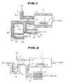
- Fig. 1 is a schematic illustration showing an apparatus for preparing a fluoride glass according to one embodiment of the invention;
- Fig. 2 is a schematic illustration showing another apparatus for preparing a fluoride glass according to another embodiment of the invention;
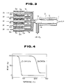
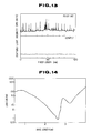
- Fig. 3 is a schematic illustration of an apparatus for preparing a preform for a fluoride optical fiber;
- Fig. 4 is a graphic representation showing the results of thermogravimetric analyses of Zr(HFA)₄ and Ba(DHO)₂;
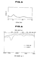
- Fig. 5 is a chart of X-ray diffraction of the 65ZrF₄-35BaF₂ glass;
- Fig. 6 is a chart showing by the real line the infrared absorption spectrum of the 65ZrF₄-35BaF₂ glass, and also showing by the broken line the infrared absorption sprectrum of a fluoride glass having the same composition and containing ZrF₄ and BaF₂ in the same molar ratio but prepared by the conventional melting process;
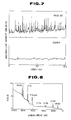
- Fig. 7 contains upper and lower charts wherein the upper chart shows the scattering distribution of the 65ZrF₄-35BaF₂ glass, and the lower chart shows the scattering distribution of a fluoride glass having the same composition and containing ZrF₄ and BaF₂ in the same molar ratio but prepared by the conventional melting process;
- Fig. 8 is a spectrum chart showing the result of X-ray photoelectron spectroscopy of the 65ZrF₄-35BaF₂ glass;
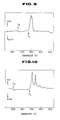
- Fig. 9 is a chart showing the result of differential thermal analysis of the 65ZrF₄-35BaF₂ glass;
- Fig. 10 is a chart showing the result of differential thermal analysis of a 57ZrF₄-34BaF₂-4. 5LaF₃-4.5AlF₃ glass;
- Fig. 11 is a chart showing the result of differential thermal analysis of a 22BaF₂-22CaF₂-16YF₃-40AlF₃ fluoride glass which has been prepared without using HF gas serving as a fluorinating agent;
- Fig. 12 is a schematic illustration showing an apparatus used for collapsing the fluoride glass according to the invention;
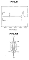
- Fig. 13 are charts showing scattering characteristics along the axes of fluoride optical fibers, wherein the upper chart shows the scattering for an optical fiber prepared in accordance with the invention and the lower chart shows the scattering for an optical fiber prepared by the conventional melting process; and
- Fig. 14 is a chart showing the transmission loss spectrum of a fluoride optical fiber prepared in accordance with the invention.
- In the process of the present invention, the barium-β-diketonate complex which constitutes the vaporizable first component and or vaporizable second component containing one or more of metal halides and β-diketonate complexes of metals other than barium may be reacted with a fluorine-containing gas through the CVD technique at a temperature of 0°C to 500°C and at a pressure of atmospheric pressure or subatmospheric pressure.
- The substrate contained in a reaction section of the reactor should have a terminal expansion coefficient approximately equal to that of the produced fluoride glass in order that the substrate causes no stress or strain to the resultant fluoride glass during the cooling step, the substrate being desirously made of a glass having excellent anticorrosive property. The fluoride glass formed is pertinently a so-called fluoride glass or calcium fluoride.
- The temperature of the substrate is maintained in a temperature of not higher than the crystallization temperature of the formed fluoride glass, preferably not higher than the glass transition temperature of the formed fluoride glass.
- One or more vaporized complexes of β-diketone and metals and fluorine-containing gases, which are introduced into the reaction section of the reactor, are reacted on the surface of the substrate or in the gas phase to form a fluoride glass. As to the configulation or state of the formed fluoride glass, a glass film or coating is formed when the fluorination reaction takes place on the surface of the substrate, and fine particles are formed due to homogeneous nucleation when the fluorination reaction takes place in the gas phase. Irrespective of either state or configulation the fluoride glass has, the vaporised complexes of β-diketone and metals and fluorine-containing glass are absorbed on the surface of the substrate or the surfaces of fine particles by chemical adsorption, and then the complexes of β-diketonate and metals and fluoride-containing gases react accompanying with theraml decomposition to form fluorinated metal fluorides. When the temperature of the substrate or the temperature of gas phase is maintained at a temperature of not higher than the galss transition temperature of the formed fluoride glass, the mobility of fluoride molecules on the growing surface is maintained at a low level so that the random adsorption state of the metal-β-diketonate complexes is frozen even after the fluorination, for example, by HF gas. As a result, the amorphous state can be frozen without any special measure similarly as in the case of being rapidly cooled by quenching. Thus, a highly homogenous fluoride glass containing no separated crystallite can be produced. A fluoride glass having a composition which could not be prepared by the conventional process because of the poor glass-forming ability can be prepared by the invention.
- In the process for preparing a fluoride glass, according to the invention, fluoride glass coatings are serially deposited on the substrate, or alternatively fine particles of fluoride glass are initially formed and then solidified. Accordingly, by varying the reaction time, the thickness of the resultant fluoride glass coating may be easily controlled. Also, a large size fluoride glass block may be produced by continuing reaction for a long time.
- A further advantage of the process for preparing a fluoride glass, according to the invention, resides in exclusion of contamination by impurities from external sources. This is due to the fact that the starting organic metal compound, i.e. a metal-β-diketonate complex, is processed continuously from the vaporization thereof to the formation of a fluoride glass without exposure to air. A still further advantage of the process of the invention resides in exclusion of contamination caused by corrosion of the wall of the crucible or container used at the melting step, since no crusible or like container is not needed in practice of the process of the invention. Upon vaporization of the starting material, impurities, such as transition elements or metals, may be separated. Accordingly, a high purity fluoride galss containing exteremely little impurity, which might cause absorption or scattering, can be prepared by this invention.
- The preform for a fluoride optical fiber, according to the invention, may be produced initially by depositing a fluoride glass over the inner peripheral wall of a cylidrical substrate and then heating the cylider to collapse the deposited glass. In accordance with the process of the invention, by heating the glass coated deposited over the inner wall of the cylinder or fine glass particles are heated to a temperature of not higher than the crystallization temperature of the formed glass while maintaining the pressure in the cylinder at a subatmospheric pressure a preform may be produced by collapsing without causing crystallization of the formed glass. Prior to collapsing, oxygen-containing impurities, such as OH groups, adsorbed on the surface of the coating or fine particles of the granules are removed by heating the glass to a temperature of not higher than the glass transition temperature while purging the interior of the cylinder with a halogen-containing gas, such as F₂, Cl₂, NF₃, CF₄, SF₆, HF or HCl. These oxygen-containing impurities cause scattering by oxides if they remain in the product, and thus should be removed. According to a further aspect of the invention, one end of the produced preform may be drawn during the heating and collapsing so that collapsing and drawing may be effected simultaneously.
- Since oxygen-containing impurities are removed by the use of a halogen-containing gas and then a preform or an optical fiber can be produced without exposing to external environment, according to the process of the invention, the resultant fluoride optical fiber is free from absorption or scattering due to the presence of impurities and has the low transmission loss. Moreover, by varying the time during which the product glass is deposited, the core/cladding diameter ratio of the optical fiber can be easily controlled. The refractive index profile of the optical fiber can also be easily controlled by changing the feed rate of the starting material continuously. The cylindrical substrate on which the fluoride glass is deposited may be selected from any materials as far as they have the viscosities approximately equal to that of the product at the temperature at which collapsing or drawing is effected in addition to the condition that the interior wall of the cylindrical substrate withstands the corrosive reaction of the fluorine-containing gas. An example of such cylindrical substrate is a cylindrical tube made of a glass, metal or polymer or a tube having multi-layered structure made of one or more of glasses, metals and/or polymers. A large size preform may be produced by selecting a material from which a large size substrate tube is prepared, so that a long fluoride optical fiber may be produced therefrom.
- The process for preparing a fluoride glass, according to the invention, realizes chemical vapor deposition of a fluoride glass which could not be practised by the conventional technology. The process of the invention produces a homogeneous fluoride glass which contains lesser amount of impurities as compared with those processed by the conventional melting processes. Alkali metals, alkaline earth metals are rare earth elements, the compounds thereof having high vapor pressures at low temperature being not known by now, form complexes with β-diketonate and the thus formed complexes have high vapor pressures at low temperature, so that the CVD process can be applied by using them to prepare fluoride glasses having the compositions which could not be produced by the conventional processes. Since the metal-β-diketonate complexes have high vapor pressures at low temperature, the processing temperature during the glass preparation step can be maintained at a low temperature. Thus, even a thermally unstable glass composition can be prepared at a temperature lower than the crystallization temperature thereof. Further, it is made possible to prepare a fluoride optical fiber having a controlled core/cladding diameter ratio and having controlled refractive index distribution, which could not be prepared by the conventional casting process.
- An exemplfied apparatus for preparing a fluoride glass, according to the invention, is shown in Fig. 1. Referring to Fig. 1, the interior of a reaction chamber 1 is controlled to have an adjusted reduced pressure by means of an evacuation system including a rotary pump, and has a fluorine-containing gas inlet 1a and a vaporizable material inlet 1b. The reaction chamber 1 is heated by a
heater 2 surrounding the reaction chamber 1. At the substantial center of the reaction chamber 1, asubstrate 3 is placed on aheater 4 to receive thereon a depositing fluoride glass. Twoevaporators vaporizable materials 5a, 5b, and are connected to the vaporizable material inlet 1b of the reaction chamber 1 through vaporizablematerial feed pipes feed pipes evaporators evaporators heaters 8a, 8b to a proper temperature. Outer peripheries of thefeed pipes heaters heater 9c. - The reaction chamber 1, the
evaporators gas feed pipes evaporators gas feed pipes - As the heat source for the
heater 4, ultraviolet rays, infrared rays, far infrared rays, radio frequencty induction plasma and microwave induction plasma may be used. - By the provision of window made of, for example, CaF₂ over the
substrate 3, the fluoride glass may be prepared while inspecting the depositing glass through a silica fiber scope. - Another embodiment of the apparatus for preparing a fluoride glass is shown in Fig. 2, wherein aluminium reaction chamber 1 is maintained at a pressure of 10 mmHg by means of a rotary pump (RP). Within the reaction chamber 1 placed is a
substrate 3 which is a plate of CaF₂. Only thesubstrate 3 is heated by aheater 2. The reaction chamber 1 has inlet ports 1a, 1b through which a gas stream containing an organic metal compound and a metal halide and a stream of a fluorine-containing gas are introduced. In a sublimation chamber,zirconium particles 5 are reacted with a bromine gas to form ZrBr₄. The reaction chamber 1 is supplied with ZrBr₄ while using argon as a carrier gas through afeed pipe 7 which is connected through a variable leak valve to the inlet port 1a. - On the other hand, a metal-β-diketonate complex of an organic metal compound is vaporized and fed to the reaction chamber 1 while using argon as a carrier gas. The inlet port 1a is connected to a feed pipe through a variable leak valve. A feed pipe 11 is connected to an
evaporator 14 which is surrounded by afeed furnace 12, a beta-diketonate metal complex 13 being contained in theevaporator 14. Argon is introduced into the mass of metal-β-diketonate complex 13 while heating theevaporator 14 so that the vaporized metal-β-diketonate complex is fed to the reaction chamber 1. - As the fluorine-containing gas, hydrogen fluoride gas HF is fed through a feed pipe 11 and an inlet port 1b to the reaction chamber 1. A variable leak valve adjusts the feed rate of HF. A fluoride glass is deposited on the
substrate 3 in the reaction chamber 1 by the thermal decomposition of the metal-β-diketonte complex and the fluorination by the metal halide and hydrogen fluoride gas. - Fig. 3 shows an apparatus for preparing a preform for fluoride optical fibers. In fig. 3, a reaction chamber 1 is evacuated by an evacuation system having a rotary pump so that the pressure in the reaction chamber 1 is adjustably reduced to subatmosphric pressure. The reaction chamber 1 is made of aluminium and has an inlet port 1a through which a voporizable starting material is interoduced and another inlet port 1b through which a fluorine-containing gas is introduced. The reaction chamber 1 is maintained
t 250°C, in its entirety, by aheater 2, and the pressure in the chamber 1 is maintained at a pressure of 10 mmHg. - Into the reaction chamber 1, a
cylindrical tube 3 is disposed and made of a fluoride glass having a composition in molar ratio of 39.7ZrF₄-13.3HfF₄-18.0BaF₂⁻4.0LaF₃-3.0AlF₃-22NaF. Through the inlet ports 1a, 1b of the reaction chamber 1 introduced are a gas stream of a metal-β-diketonate complex and a fluorine-containing gas, respectively. - In order that the invention should be more fully understood, presently preferred Examples of the invention will be set forth below. However, it is to be noted that the following Examples are given by way of example only and not intended to limit the scope of the invention which is definitely recited in the appended claims.
- In the apparatus shown in Fig. 1, a complex Zr(HFA)₄ which was a complex of hexafluoroacetylacetone (hereinafter referred to as HFA) and zirconium was used together with a complex Ba(DHO)₂ which was a complex of 2,2-dimethyl-6,6,7,7,8,8,8-heptafluoro-3,5-octanedione (hereinafter referred to as DHO)and barium. Hydrogen fluoride gas (HF) was used as the fluorine-containing gas. The interior of the reaction chamber 1 was maintained at a pressure of
10 mmHg, and maintained at 205°C by using theheater 2. Thesubstrate 3 is a CaF₂ plate which was heated to 250°C by theheater 4. - The results of thermogravimetric analyses of Zr(HFA)₄ and Ba(DHO)₂ used as the vaporizable materials are shown in Fig. 4. Weight decrease due to vaporization was observed at about 60°C for Zr(HFA)₄ and at about 200°C for Ba(DHO)₂. Zr(HFA)₄ was maintained at 60°C in the
evaporator 6a by means of the heater 8a and Ba(DHO)₂ was maintained at 200°C in theevaporator 6b by means of theheater 8b. The voporized gases were introduced into the reaction chamber 1 while being carried by argon supplied from a not-shown carrier gas supply means. The feed rate of HF was controlled by a mass flow controller. Thefeed pipes heaters - Zr(HFA)₄ and Ba(DHO)₂ introduced in the reaction chamber 1 were converted into fluorides in the gaseous phase by the following reactions, and deposited on the
substrate 3 to form a fluoride glass.
Zr(HFA)₄(g) + 4HF(g) → ZrF(g) + 4HFA(g)
Ba(DHO)₂(g) + 2HF(g) → BaF₂(g) + 2DHO(g)
xZr(DHO)₂(g) + yBaF₂(g) → xZrF₄ + yBaF₂(s) - In the reaction equations set forth above, (g) indicates the gaseous state and (s) indicates the solid phase.
- ZrF₄ and BaF₂ formed by the above reactions and deposited on the
substrate 3 had a low mobilities on the substrate since the temperature of the substrate was maintained at a temperature lower than the transition temperatures of the fluoride glasses, and thus frozen in situ without changing the positions. As a result, the non-equilibrium state was realized similarly as in the case of quenching. The fluoride glasses were serially deposited to prepare a glass coating or a glass bulk. - The fluorination reactions of Zr(HFA)₄ and Ba(DHO)₂ took place independently. The rates of preparation of ZrF₄ and BaF₄ by the reaction between Zr(HFA)₄ and HF and between Ba(DHO)₂ and HF were kept unchanged in the reaction of Zr(HFA)₄-Ba(DHO)₂-HF. Accordingly, the Zr/Ba ratio in the formed glass could be easily controlled by adjusting the flow rate of argon used as the carrier gas.
- In this Example, Zr(HFA)₄ was supplied at a feed rate of 100 cc/min, Ba(DHO)₂ was supplied at a feed rate of 50 cc/min and HF was supplied at a feed rate of 150 cc/min and reaction was continued for 2 hours, whereby a glass block having a composition of 65ZrF₄-35BaF₂ was obtained.
- The X-ray diffraction chart of the thus prepared glass is shown in Fig. 5, and the infrared absorption spectrum chart is shown in Fig. 6. In Fig. 6, the infrared absorption spectrum of a fluoride glass having the same composition and prepared by the conventional melting process is shown by the broken line. The distribution of scattered light intensity relative to the substrate of 65ZrF₄-35BaF₂ glass upon launching of a He-Ne laser was measured. For comparison purpose, a similar scattering distribution of a fluoride glass prepared through the conventional process is also shown in Fig. 7. The lower chart of Fig. 7 shows the scattering distribution of the 65ZrF₄-35BaF₄ prepared by the process of the invention, and the upper chart in Fig. 7 shows the scattering distribution of a glass having the same composition and prepared by the conventional process.
- In the X-ray diffraction chart, the fluoride glass prepared by this Example does not show a diffraction peak due to the presence of crystal. In the infrared absorption spectrum, the fluoride glass prepared by this Example does not show an absorption peak at about 2.9 µm due to the presence of OH group, whereas the fluoride glass prepared by the conventional process show an absorption due to the presence of OH group. It is appreciated from the result of infrared absorption spectrum that the fluoride glass prepared by the process of this invention is a fluoride glass in which the concentration of hydroxyl group is extremely low. In should be appreciated, by comparing the results of the fluoride glass prepared by the conventional process, that the scattering of oxides is significantly dcreased. In the fluoride glass prepared by the conventional process, a protion of hydroxyl group present on the surfaces of starting materials remains and forms oxides during the melting step to be scattered in the formed glass. On the contrary, the fluoride glass of the invention is prepared through continuous steps including the step of vaporizing the starting materials and the step of formation of glass, leading to reduction of oxide impurities as shwon in Fig. 7.
- Fig. 8 is a spectrum chart showing the result of X-ray photoelectron spectroscopy of 65ZrF₄-35BaF₂ glass. The fluoride glass prepared by the process of the invention is composed only of zirconium, barium and fluorine and signals showing the presence of C1S and O1S are not detected to show that no organic materials are present. It should be appreciated from the result that the reaction between a metal-β-diketonate complex and a fluorine-containing gas can be proceeded at a low temperature to prevent remaining of impurities in the resultant glass. Since the metal-β-diketonate complex in the process of this invention can be vaporized at a low temperature so that the temperature throughout the overall preparation step can be maintained at a relatively low temperature, a homogenous glass can be prepared at a temperature lower than the crystallization temperature of the formed fluoride glass even for the preparation of fluoride glasses which have low glass transition temperatures and are thermally unstable.
- By using β-diketonate complexes of other metal elements, fluoride glasses containing different metallic constituents may be prepared. The compositions of formed fluoride glasses may be easily controlled by adjusting the flow rate of argon used as the carrier gas. The result of differential thermal analysis of 65ZrF₄-35BaF₂ glass is shown in Fig. 9. The glass transition temperature of the glass was 270°C and the crystallization temperature was 330°C.
-
- The same apparatus used in Example 1 and shown in Fig. 1 was used. Additional two evaporators similar to the
evaporators feed pipe 7b. Similarly as in Example 1, a fluoride glass was prepared. La(DHO)₃ was contained and maintained at 180°C in one of the additional evaporators, and Al(DHO)₃ was contained and maintained at 90°C in the other of the additional evaporators. - A 5.5 mm thick glass was deposited on a CaF₂ substrate for a reaction time of 2 hours. The formed fluoride glass has a composition, in mol%, 57ZrF₄-34BaF₂-4.5LaF₃-4.5AlF₃.
- The formed fluoride glass had an improved thermal stability by the addition of LaF₃ and AlF₃, and no change in density of scatters was observed even after subjected to a heating treatment for an hour.
- The result of differential thermal analysis of the 57ZrF₄-34BaF₂-4.5LaF₃-4.5AlF₃ glass prepared by Example 2 is shown in Fig. 10. The glass transition temperature of the glass was 301°C, and the crystallization temperature thereof was 395°C.
- A fluoride glass was prepared similarly as in Example 2 except that triethylaluminium Al(C₂H₅)₃ was contained in the evaporator in place of Al(DHO)₃ while using a similar apparatus as used in Example 2. The evaporator containing Al(C₂H₅)₃ was maintained at 40°C.
- A glass having a thickness of about 5.5 mm was deposited on the CaF substrate for a reaction time of 2 hours. The formed fluoride glass had the same composition as that of the glass prepared by Example 2, the composition of the formed glass being represented by 57ZrF₄-34BaF₂-4.5LaF₃-4.5AlF₃. The result of X-ray photoelectron spectroscopy revealed that no carbon was remained in the resultant glass. The results of infrared spectroscopy, X-ray diffraction.scattering distribution analysis and differential thermal analysis were equivalent to those of the glass prepared by Example 2, and it was revealed that an optically homogenous glass could be prepared by using organic metal compounds in lieu of β-diketonate complexes. Likewise, glasses could be prepared by using 2,2-dimethyl-6,6,7,7,8,8,8-heptafluoro-3,5-octanedion (DHO) complexes of other rare earth metal elements, such as Ce, Pr, Nd, Pm, Sm, Eu, Gd, Tb, Dy, Ho, Er, Tm, Yb and Lu, are used in place of the complex of La. The results of differential thermal analyses showed that the glasses had equivalent thermal stabilities. Particularly, a glass having no absorption peak within the medium infrared region was obtained by using a complex of Gd.
- While using the same apparatus as used in Example 1 and shown in Fig. 1, three additional evaporators were provided similarly as Example 2 and a fluoride glass was prepared through a similar procedure as described in Example 2. The additional evaporators contained La(DHO)₃, Al(DHO)₃ and Na(TMH) and matintained, respectively, at 180°C, 60°C and 150°C.
- A glass having a thickness of about 6.5 mm was deposited on the CaF₂ substrate within a reaction time of 2 hours. The formed glass had a composition represented by 51ZrF₄-20BaF₂-4.5LaF₃-4.5AlF₃-20NaF (in mol%).
- By the addition of NaF to the fluoride glass of Example 2, the thermal stability of the fluoride glass was improved. The density of scatters was not changed even after the thermal treatment effected at 300°C for 5 hours. The result of differential thermal analysis showed that the glass prepared by this Example had a glass transition temperature of 260°C and a crystallization temperature of 373°C. A similar glass was prepared by using Li(TMH) in place of Na(TMH), and the formed glass containing 20 mol% of LiF was subjected to differential thermal analyssis to reaveal that it had a glass transition temperature of 252°C and a crystallization temperature of 348°C.
- Also the La(DHO)₃ was mixed, respectively, with 2,2-dimethyl-6,6,7,7,8,8,8-heptafluoro-3,5-octanedion (DHO) complexes of In, Sn, Pb, Sb, Bi, Zn, Cd, Ti. Th, Nb, Ta, Mo and Mn to prepare glasses containing 1 to 10 mol% of each of fluorides of these metals. The fluoride glasses showed a crystallization temperature shift by 2 to 15°C to the lower temperature side, as compared to the glass of this Example. Each of these glasses had a thickness of about 5 mm and no scattering was observed.
- A fluoride glass was prepared similarly as in Example 2 except that Hf(HFA)₄ was charged in the evaporator in place of Zr(HFA)₄. The evaporators charged with Hf(HFA)₄, Ba(DHO)₂, La(DHO)₃ and Al(DHO)₃ were maintained, respectively, at 55°c, 200°C, 180°C and 90°C. The feed rates were 100cc/min for Hf(HFA)₄, 150 cc/min for Ba(DHO)₂, 13 cc/min for La(DHO)₃, 13 cc/min for 2Al(DHO)₃ and 200 cc/min for HF.
- The reaction was continued for 2 hours, whereby a fluoride glass having a thickness of about 5 mm was deposited on the CaF₂ substrate. The result of elementary anlaysis through the X-ray photoelectron analyssis revealed that the formed glass had a composition in molar ratio of 57HfF₄-34BaF₄-4.5LaF₃-4.5AlF₃. The refractive index of the thus formed glass was nD = 1.50.
- The result of differential thermal analysis revealed that the glass transition temperature of the glass was 315°C and the crystallization temperature was 403°C. Thus, an HfF₄ system fluoride glass having a thermal stability substantially equivalent to that of the ZrF₄ system glass was prepared.
- A fluoride glass was prepared similarly as in Example 2, except that Ba(DHO)₂, Ca(DHO)₂, YDHO)₃ and Al(DHO)₃ were used as the starting materials and the hydrogen fluoride (HF) gas was not used as the fluorine-containing gas.
- The evaporators charged with Ba(DHO)₂, Ca(DHO)₂, YDHO)₃ and Al(DHO)₃ were maintained, respectively, at 200°C, 180°C, 140°C and 95°C. The feed rates of the metal-β-diketonate complexes were kept at 55 cc/min for Ba(DHO)₂, 55 cc/min for Ca(DHO)₂, 40 cc/min for YDHO)₃ and 100 cc/min for Al(DHO)₃. The temperature of the substrate was maintained at 380°C. The reaction was continued for 2 hours to obtain an about 8 mm thick fluoride glass depostited on the CaF₂ glass. The formed fluoride glass was analysed by the X-ray photoelectron analysis to find that it had a composition of 22BaF₂-22CaF₂-16YF₃-40AlF₃ (molar ratio). No residual carbon was observed. It was thus found that the ligands of β-diketonate complexes used as the starting materials were decomposed in the gaseous phase to act as the fluorinating agents. Meantime, DHO is represented by 2,2-dimethyl-6,6,7,7,8,8,8-heptafluoro-3,5-octanedione and thus contains fluorine atoms. The result of differential thermal analysis of the formed fluoride glass is shown in Fig. 11. The result shows that the glass transition temperature of the formed fluoride glass is 430°C, and the crystallization temperature thereof is 560°C. While the crystallization temperature of a fluoride glass having the same composition and prepared through the conventional melting process is 535°C, and thus the crystallization temperature of the fluoride glass obtained by the process of the invention is higher than that of the glass prepared by the conventional process by 25°C. This shows that the thermal stability of the fluoride glass prepared by the present invention is improved over that of the fluoride glass prepared by the conventional melting process. The improvement in thermal stability was attributed by removal of oxide impurities in the fluoride glass prepared according to the invention, the oxide impurities being not removed in the fluoride glass prepared by the conventional fusing process. The refractive index of the fluoride glass prepared by this Example was nD = 1.44. Fluoride glasses were prepared by using Sr(DHO)₂ and Ca(DHO)₂ in place of Mg(DHO)₂ and using MgF₂ and SrF₂ as the substrate in place of CaF₂. About 7 mm thick glasses free of scatters were prepared.
- A fluoride glass was deposited on the substrate while using the apparatus shown in Fig. 2. ZrBr₄ and Ba(pivaloyltrifluoromethylacetyacetone)₂ (hereinafter referred to Ba(PTA)₂) were introduced through the inlet 1a. ZrBr₄ was prepared by sublimating
granular zirconium 5 form theheater 4 which was heated to 350°C and reacting the sublimated zirconium with bromine gas. - The
feed pipe 7 having the variable leak valve was connected to the container in whichgranular zirconium 5 was contained. Bromine gas and argon were fed to the container so that ZrBr₄ was sublimated by the reaction between Zr and Br₂, and the sublimated ZrBr₄ was supplied through the inlet 1a to the reaction chamber 1 together with argon. Thefeed pipe 7 is heated by theheater 9. The content of transition metal impurities in ZrBr₄ was suppressed below 1 ppb (part per billion). - On the other hand, argon acting as the carrier gas is passed through the
evaporator 14 saturated with vaporized Ba(PTA)₂, which was vaporized from solid Ba(PTA)₂ and maintained at 120°C in theevaporator 14, and through the feed pipe 11, the variable leak valve and the inlet 1a to the reaction chamber 1. A fluorine containing gas, hydrogen fluoride HF in this Example, was supplied through the feed pipe 11 and the inlet 1b to the reaction chamber 1. The feed rate of HF was adjusted by the variable leak valve. The reaction chamber 1 was maintained at 200°C and thesubstrate 3 was maintained at 250°C. - ZrBr₄ and Ba(PTA)₂ introduced into the reaction chamber 1 were converted on the
substrate 3 to ZrF₄ and BaF₂ as shown by the following reaction equations. In the following reaction equations, (g) indicates the gasesous state, (ad) indicates the adsorbed solid phase and (s) indicates the solid phase.
ZrBr₄(g) → ZrBr₄(ad)
Ba(PTA)₂(g) → Ba(PTA)₂(ad)
HF(g) → HF(ad)
ZrBr₄(ad) + 4HF(ad) → ZrF₄(s) + 4HBr(ad)
Ba(PTA)₂(ad) + 2HF(ad) → BaF₂(S) + 2(CH₃)₃-C-CO-CH₂-CO-CF₃(ad)
HBr(ad) → HBr(g)
(CH₃)₃C-CO-CH₂-CO-CF₃(ad) → (CH₃)₃C-CO-CH₂-CO-CF₃(g) - Since the temperature of the substrate is lower than the glass transition temperature of the formed fluoride glass, ZrF₄ and BaF₂ formed by the above reactions and deposited on the
substrate 3 had low mobilities and then frozen in situ on thesubstrate 3. Accordingly, likewise in the case of quenching, a non-equilibrium state can be realized on thesubstrate 3. A glass bulk may be prepared by continuing deposition of the fluoride glass. - In the reactions described above, fluorinations of ZrBr₄ and Ba(PTA)₂ by HF take place independently from each other. Therefore, the production rate of ZrF₄ by the reaction of ZrBr₄-HF system and the production rate are of BaF₂ by the reaction of Ba(PTA)₂-HF system are maintained also in the reaction system of ZrBr₄-Ba(PTA)₂-HF. Accordingly, the ratio of Zr/Ba in the formed glass can be easily controlled.
- In this Example, the feed rates were 100 cc/min for ZrBr₄, 70 cc/min for Ba(PTA)₂ and 150 cc/min for HF. After reacting for 3 hours, a 6.5 mm thick fluoride glass having a composition of 60ZrF₄-40BaF₂ was formed.
- The results of X-ray diffraction, infrared absorption spectroscopy and anaysis of scattering distribution measured by launching a He-Ne laser into the glass block were substantially equivalent to those described in Example 1.
- The result of radioactivation analysis of the formed fluoride glass revealed that the contant of Fe, Cu, Ni. Co and Cr were less than 1 ppb (part per billion) which was the detection limit of the radioactivation analyssis.
- Further, by varying the feed rates of the starting materials, fluoride glasses having various compositions were prepared and the thus prepared fluoride glasses were analysed through the fluorescent X-ray analysis. Fluoride glass blocks having widely distributed compositions ranging within 90ZrF₄-10BaF₂ to 35ZrF-65BaF₂ were formed. It was hard to prepare fluoride glasses having such compositions by the conventional melting or casting processes.
- The fluoride glass block prepared by Example 6 and having the composition of 60ZrF₄-40BaF₂ was cut to have a rod shape and the surface thereof was polished to be used as a deposition substrate.
- The heating means for glass deposition was changed from heater heating to CO₂ laser heating and the deposition substrate was changed from CaF₂ to a glass rod, the remaining conditions and the used apparatus being the same as used in Example 6, whereby a fluoride optical fiber preform was prepared.
- The glass rod had an outer diameter of 4 mm and a length of 300mm. Both ends of the glass rod were clamped by chucks, and a glass was deposited on the glass rod while the glass rod was rotated at 60 rpm and moved along its longitudinal direction at a moving speed of 10 mm/min. In order to establish a desired distribution of refractive index, AlBr₃ was introduced in addition to ZrBr₄ and Ba(PTA)₂ to deposite serially on the glass rod substrate a fluoride glass having a composition of 58ZrF₆-37BaF₂-5AlF₃ which is to be used as a fluoride optical fiber preform. The feed rates of the starting materials were 30 cc/min for ZrBr₄, 14 cc/min for Ba(PTA)₂ and 2 cc/min for AlBr₃. The temperature of the glass rod substrate was 250°C.
- The preform had a diameter of 8mm and a length of 300mm, and the relative refractive index difference between the core and the cladding was 0.7%. The preform was drawin into a fluoride optical fiber having a length of 500 meters. The transmission loss of the optical fiber was measured. The minimum loss was 8 db/km at 2.55 um. The result reveals that a long fluoride optical fiber having low loss can be produced by the invention.
- Used starting materials were Ba(DHO)₂ which was a complex of Ba with 2,2-dimethyl-6,6,7,7,8,8,8-heptafluoro-3,5-octanedione (DHO), Zr(HFA)₄ which was a complex of Zr with hexafluoroacetylacetone (HFA), La(DHO)₃ complex, Al(DHO)₃ complex and Na(DHO) complex. These five starting materials, Ba(DHO)₃, Zr(HFA)₄, La(DHO)₃, Al(DHO)₃ and Na(DHO), were vaporized by heating and maintaining in the gaseous state, respectively, at 210°C, 60°C, 180°C, 70°C and 190°C, and supplied into the reaction chamber while using argon as the carrier gas. Using the apparatus shown in Fig. 3, aluminium evaporators 8a to 8e charged respectively with complexes Ba(DHO)₃, Zr(HFA)₄, La(DHO)₃, Al(DHO)₃ and Na(DHO) were heated and argon gas was introduced into respective evaporators so that vaporized starting materials were supplied through an
aluminum feed pip 7 and the inlet 1a into the reaction chamber 1. - As a fluorine-containing gas, a mixed gas of HF(95 vol%)-F₂(5 vol%) was supplied through the
feed pipe 4 and the inlet 1b into the reaction chamber 1. - The feed rate of the metal-β-ketonate complexes and the mixed gas could be adjusted by means of mass flow controllers.
- Using heaters, the
feed pipes 7a to 7e were maintained at 215°C, 65°C, 185°C, 75°C and 195°C in order to prevent condensation of gases. - The β-diketonate complexes of respective metals introduced into the reaction chamber 1 were converted to fluorides in a form of fine glass particles due to homogeneous nucleation in the gaseous phase.
- In fluorination by HF of β-diketonate complexes of respective metals, Ba(DHO)₃, Zr(HFA)₄, La(DHO)₃, Al(DHO)₃ and Na(DHO), respective complexes are fluorinated independently so that the composition of resultant glass can be easily controlled by varying the feed rates of respective complexes.
- In this Example, reaction was continued for 2 hours while maintaining the feed rates of the starting materials at 50 cc/min for Ba(DHO)₃, 100 cc/min for Zr(HFA)₄, 10 cc/min for La(DHO)₃, 7.5 cc/min for Al(DHO)₃ and 7.5 cc for Na(DHO) and 15 cc/min for HF-F mixture gas. The composition of fine glass particles was 53ZrF₄-20BaF₂-4LaF₃-3AlF₃-22NaF, and the formed product was deposited on the interior wall of the
cylindrical glass tube 3. The composition of the cylindrical glass was 39.7ZrF₄-13.3HfF₄-18.0BaF₂-4.0LaF₃-3.0AlF₃-22NaF. - Fig. 12 shows schematically an apparatus used for collapsing a cylindrical tube having its interior wall deposited with fine glass particles.
- Both ends of the
cylindrical glass tube 3 having fine glass particles deposited over the interior wall by the process as aforementioned were allowed to contact with analuminum connector 18, and the internal pressure of the cylindrical tube was controlled to 500 mmHg while introducing F₂ gas from the downside as viewed in Fig. 12 and evacuating by a rotary pump (not shown) from the upside as viewed in Fig. 12. The temperature was set to 200°C by aheater 12, and processing was continued for 2 hours. The temperature was then raised to 280°C to collapse entirely, whereby a preform was obtained. - In this Example, a cylindrical tube of fluoride glass having an outer diameter of 12 mm, an inner diameter of 8 mm and a legth of 150 mm was used. However, by increasing the diameter of the used glass tube, the size of the preform can be further increased. For instance, a cylindrical tube having an outer diameter of 20mm, and inner diameter of 12 mm and a length of 300 mm was used and deposition of fine glass particles was effected for 3 to 5 hours, followed by collapsing, whereby a large size collapsed preform was obtained.
- In collapsing the
cylindrical tube 13 deposited withfine glass particle 20, it is desirous that the temperature is maintained within the range of from 50°C to 500°C, although the temperature may be changed corresponding to the composition of the fluoride glass. - Fluorine gas was used in this Example to remove oxide impurites absorbed on the surface of the deposited particles. However, other halogen-containing gases, such as gaseous compounds of fluorine or chlorine with hydrogen, carbon, nitrogen, boron, sulfur and silicon or mixture of at least two of said gases, may also be used for this purpose.
- The collapsed preform prepared by Example 9 was placed in an drawing furnace filled with an inert gas, and drawn at 285°C into a fluoride optical fiber.
- A He-Ne laser was launched into the thus produced fluoride optical fiber and the scattered light intensity along the fiber axis was measured. For comparison purpose, the scattering distribution of a fluoride fiber produced by the convetional casting process was also measured. The results are shown in Fig. 13.
- It is apparently seen from Fig. 13 that scatters can be significantly reduced according to the process of the invention. In the process of the invention, vaporization of the starting materials for glass and deposition or synthesis of glass particles can be effected by a single step. As an advantageous result of the single step processing, fine glass particles containing no oxide impurites could be produced. The oxide impurities adsorbed on the surface of the deposited mass could be removed by treatment with a fluorine-containing gas, without exposing to the outside atmosphere, whereby a preform was obtained.
- The transmission loss of the produced optical fiber was measured. The result is shown in Fig. 14. the minimum loss at 2.55 um of the produced optical fiber was 0.9 db/km which was not attainable by the conventional technology, with the length being so long as could not be produced by the conventional technology.
- Generally following to the procedure as described in Example 9, fine particles of a fluoride glass constituting the core composition was deposited over the interior wall of a
glass tube 3 constituting the cladding glass composition. The glass tube was then placed in an drawing furnace where it was processed at 200°C for an hour in a flowing F₂ gas stream. Thereafter, the internal pressure was set to 700 Torr by evacuating the interior of the tube from the upper end which was connected to a rotary pump. The drawing furnace was heated to 285°C and the glass tube was elongated simultaneously with collapsing operation to obtain a fluoride optical fiber having a minimum loss of 0.7 db/km at 2.55 µm. A long fluoride optical fiber having a low loss factor was produced by the Example, by simultaneous drawing and collapsing. Similar effects can be obtained by using Cl₂, HF, HCl, BF₃, SF₆, SiF₄, CF₄ or a mixture thereof in place or in addition of F₂ in the processing step with a halogen-containing gas carried out prior to the drawing step. -
- A fluoride optical fiber was produced similarly as in Example 10 except that a Tefron (Trade name) FEP tube was used in place of the glass tube.
- In addition to the metal-β-diketonate complexes used in Example 10, Hf(HFA)₄ was used. The feed rates of respective metal-β-diketonate complexes are set forth below:
Zr(HFA)₄ --- 87.5 cc/min
Hf(HFA)₄ --- 12.5 cc/min
Ba(DHO)₂ --- 45 cc/min
La(DHO)₃ --- 10 cc/min
Al(DHO)₃ --- 7.5 cc/min
Na(DHO) --- 40 cc/min
The flow rate of HF-F₂ was 100 cc/min. Glass particles were deposited over the interior wall of the FEP (fluoroethylene pipe) tube. The deposited fine glass particles had a composition of 39.7ZrF₄-13.3HfF₂-18.0BaF₂-4.0LaF₂-3.0AlF₃-22NaF. Thereafter, feeding of Hf(HFA)₄ was stopped to form a core layer. Then, in order to form a core layer, feed rates of respective metal-β-diketonate complexes were adjusted to the rates as set forth below:
Zr(HFA)₄ --- 100 cc/min
Ba(DHO)₂ --- 50 cc/min
La(DHO)₃ --- 10 cc/min
Al(DHO)₃ --- 7.5 cc/min
Na(DHO) --- 40 cc/min
The deposition was effected for 2 hours with the flow rates of the starting materials as set forth above and the flow rate of HF-F₂ was set to 100 cc/min. the composition of the formed glass was 53ZrF₄-20BaF₂-4LaF₃-3AlF₃-22NaF. - The fluoride glass deposited on the interior wall of the FET (fluoroethylene pipe) tube and including the cladding layer and core layer was drawn similarly as described in Example 10. The thus produced fluoride optical fiber covered by a Teflon FEP had a long size and a low transmission loss. The core/cladding diameter ratio may be freely changed by varying the times for deposition of fine fluoride glass particles for the formations of core and cladding layers.
- Aluminium was coated by vapor deposition over the interior wall of a tube made of an oxide glass having a composition of 22B₂O₃-48PbO-30Tl₂O₃. This oxide glass tube was used in place of the FEP tube as used in Example 12. The following procedure was the same as described in Example 12 to deposite fluoride glasses followed by collapsing and drawing to produce fluoride optical fiber having a appreciable length and low loss. The cylindrical tube used as the substrate on which fine particle of fluoride glass is deposited, may be a single layer or multi-layered cylindrical tube made of any of glasses, metal and organic polymers.
Claims (15)
a barium β-diketonate complex serving as a first starting material and represented by the following general formula (1) of:

a gaseous or vaporizable compound of the matallic element constituting said fluoride glass, the gaseous or vaporizable compound serving as a second starting material; and
a fluorine-contained gas serving as fluorinating agent.
a barium β-diketonate complex serving as a first starting material and represented by the following general formula (1) of:

a gaseous or vaporizable compound of the matallic element constituting said fluoride glass, the gaseous or vaporizable compound serving as a second starting material.
a barium β-diketonate complex serving as a first starting material and represented by the following general formula (1) of:

a gaseous or vaporizable compound of the matallic element constituting said fluoride glass, the gaseous or vaporizable compound serving as a second starting material; and;
a fluorine-contained gas serving as a fluorinating agent; and
the process being further characterized in that said cylindrical substrate containing therein deposited coating or fine particles of a fluoride glass is heated to solidify the same to form a preform for optical fibers.
a barium β-diketonate complex serving as a first starting material and represented by the following formula (1) of:

a gaseous or vaporizable compound of the matallic element constituting said fluoride glass, the gaseous or vaporizable compound serving as a second starting material, and;
a fluorine-contained gas serving as a fluorinating agent; and
the process being further characterized in that said rod-like glass substrate containing thereon a lyer or deposited fine particles of a fluoride glass is heated to solidify the same to form a preform for optical fibers.
Applications Claiming Priority (8)
| Application Number | Priority Date | Filing Date | Title |
|---|---|---|---|
| JP4979788 | 1988-03-04 | ||
| JP49797/88 | 1988-03-04 | ||
| JP27600788 | 1988-11-02 | ||
| JP276007/88 | 1988-11-02 | ||
| JP1640389 | 1989-01-27 | ||
| JP16403/89 | 1989-01-27 | ||
| JP1049277A JPH02275726A (en) | 1988-03-04 | 1989-03-01 | Fluoride glass and production of preform for optical fiber using the same |
| JP49277/89 | 1989-03-01 |
Publications (3)
| Publication Number | Publication Date |
|---|---|
| EP0331483A2 true EP0331483A2 (en) | 1989-09-06 |
| EP0331483A3 EP0331483A3 (en) | 1990-08-16 |
| EP0331483B1 EP0331483B1 (en) | 1993-05-12 |
Family
ID=27456571
Family Applications (1)
| Application Number | Title | Priority Date | Filing Date |
|---|---|---|---|
| EP89302073A Expired - Lifetime EP0331483B1 (en) | 1988-03-04 | 1989-03-02 | Process for the preparation of fluoride glass and process for the preparation of optical fiber preform using the fluoride glass |
Country Status (2)
| Country | Link |
|---|---|
| US (1) | US5071460A (en) |
| EP (1) | EP0331483B1 (en) |
Cited By (16)
| Publication number | Priority date | Publication date | Assignee | Title |
|---|---|---|---|---|
| EP0420240A2 (en) * | 1989-09-29 | 1991-04-03 | Hoya Corporation | Halide laser glass and laser device utilizing the glass |
| US5204314A (en) * | 1990-07-06 | 1993-04-20 | Advanced Technology Materials, Inc. | Method for delivering an involatile reagent in vapor form to a CVD reactor |
| US5225561A (en) * | 1990-07-06 | 1993-07-06 | Advanced Technology Materials, Inc. | Source reagent compounds for MOCVD of refractory films containing group IIA elements |
| US5280012A (en) * | 1990-07-06 | 1994-01-18 | Advanced Technology Materials Inc. | Method of forming a superconducting oxide layer by MOCVD |
| US5453494A (en) * | 1990-07-06 | 1995-09-26 | Advanced Technology Materials, Inc. | Metal complex source reagents for MOCVD |
| US5536323A (en) * | 1990-07-06 | 1996-07-16 | Advanced Technology Materials, Inc. | Apparatus for flash vaporization delivery of reagents |
| EP0814062A1 (en) * | 1996-06-21 | 1997-12-29 | Yamamura Glass Co. Ltd. | Process for producing a thin film of a metal fluoride on a substrate |
| US6126996A (en) * | 1990-07-06 | 2000-10-03 | Advanced Technology Materials, Inc. | Metal complex source reagents for chemical vapor deposition |
| EP1188545A2 (en) * | 2000-09-13 | 2002-03-20 | Carl Zeiss | Method for heating a work piece, in particular an optical element |
| US6935050B2 (en) | 2002-12-04 | 2005-08-30 | Corning Incorporated | Method and apparatus reducing metal impurities in optical fiber soot preforms |
| EP1586542A1 (en) * | 2004-04-05 | 2005-10-19 | Humboldt-Universität zu Berlin | Method for the preparation of fluoride glass gel and use thereof |
| US8299286B2 (en) | 1990-07-06 | 2012-10-30 | Advanced Technology Materials, Inc. | Source reagent compositions and method for forming metal films on a substrate by chemical vapor deposition |
| US9864108B2 (en) | 2013-12-20 | 2018-01-09 | Norvartis Ag | Molds for making contact lenses |
| US9981435B2 (en) | 2014-12-17 | 2018-05-29 | Novartis Ag | Reusable lens molds and methods of use thereof |
| US9981436B2 (en) | 2014-12-17 | 2018-05-29 | Novartis Ag | Reusable lens molds and methods of use thereof |
| US10232574B2 (en) | 2014-12-17 | 2019-03-19 | Novartis Ag | Reusable lens molds and methods of use thereof |
Families Citing this family (18)
| Publication number | Priority date | Publication date | Assignee | Title |
|---|---|---|---|---|
| FR2695943B1 (en) * | 1992-09-18 | 1994-10-14 | Alsthom Cge Alcatel | Process for the vapor phase deposition of a fluorinated glass film on a substrate. |
| US6121164A (en) * | 1997-10-24 | 2000-09-19 | Applied Materials, Inc. | Method for forming low compressive stress fluorinated ozone/TEOS oxide film |
| US7094284B2 (en) * | 1999-10-07 | 2006-08-22 | Advanced Technology Materials, Inc. | Source reagent compositions for CVD formation of high dielectric constant and ferroelectric metal oxide thin films and method of using same |
| US20020041750A1 (en) * | 2000-06-20 | 2002-04-11 | Chacon Lisa C. | Rare earth element-doped, Bi-Sb-Al-Si glass and its use in optical amplifiers |
| US7018504B1 (en) * | 2000-09-11 | 2006-03-28 | Asm America, Inc. | Loadlock with integrated pre-clean chamber |
| US6899507B2 (en) | 2002-02-08 | 2005-05-31 | Asm Japan K.K. | Semiconductor processing apparatus comprising chamber partitioned into reaction and transfer sections |
| JP5280861B2 (en) * | 2006-01-19 | 2013-09-04 | エーエスエム アメリカ インコーポレイテッド | High temperature ALD inlet manifold |
| US8440048B2 (en) * | 2009-01-28 | 2013-05-14 | Asm America, Inc. | Load lock having secondary isolation chamber |
| US20120276291A1 (en) * | 2011-04-28 | 2012-11-01 | Bird Chester D | Methods and Apparatuses for Reducing Gelation of Glass Precursor Materials During Vaporization |
| US9574268B1 (en) | 2011-10-28 | 2017-02-21 | Asm America, Inc. | Pulsed valve manifold for atomic layer deposition |
| US9388492B2 (en) | 2011-12-27 | 2016-07-12 | Asm America, Inc. | Vapor flow control apparatus for atomic layer deposition |
| RU2539455C1 (en) * | 2013-12-23 | 2015-01-20 | Федеральное Государственное Автономное Образовательное Учреждение Высшего Профессионального Образования "Дальневосточный Федеральный Университет" (Двфу) | Method of obtaining fluoride glass |
| US10662527B2 (en) | 2016-06-01 | 2020-05-26 | Asm Ip Holding B.V. | Manifolds for uniform vapor deposition |
| US11492701B2 (en) | 2019-03-19 | 2022-11-08 | Asm Ip Holding B.V. | Reactor manifolds |
| KR20210048408A (en) | 2019-10-22 | 2021-05-03 | 에이에스엠 아이피 홀딩 비.브이. | Semiconductor deposition reactor manifolds |
| EP3950611A1 (en) * | 2020-08-06 | 2022-02-09 | Heraeus Quarzglas GmbH & Co. KG | Alternative fluorinating agent for the preparation of fluorinated quartz glass |
| EP3950610A1 (en) * | 2020-08-06 | 2022-02-09 | Heraeus Quarzglas GmbH & Co. KG | Alternative fluorinating agent ii: fluid and soot accumulation |
| CN113461505B (en) * | 2021-06-30 | 2022-07-26 | 湖北大学 | High-stability and volatile heteronuclear rare earth chelate as well as preparation method and application thereof |
Citations (2)
| Publication number | Priority date | Publication date | Assignee | Title |
|---|---|---|---|---|
| WO1986007348A1 (en) * | 1985-06-03 | 1986-12-18 | Hughes Aircraft Company | Method for introducing dopants in optical fiber preforms |
| US4718929A (en) * | 1983-10-21 | 1988-01-12 | Corning Glass Works | Vapor phase method for making metal halide glasses |
Family Cites Families (7)
| Publication number | Priority date | Publication date | Assignee | Title |
|---|---|---|---|---|
| JPS57175743A (en) * | 1981-04-20 | 1982-10-28 | Nippon Telegr & Teleph Corp <Ntt> | Preparation of base material for fluoride optical fiber |
| US4378987A (en) * | 1981-10-15 | 1983-04-05 | Corning Glass Works | Low temperature method for making optical fibers |
| JPS605046A (en) * | 1983-06-22 | 1985-01-11 | Showa Electric Wire & Cable Co Ltd | Manufacture of metal-coated optical fiber |
| IT1168841B (en) * | 1983-09-15 | 1987-05-20 | Cselt Centro Studi Lab Telecom | PROCEDURE FOR THE PRODUCTION OF LOW ATTENUATION OPTICAL FIBERS IN THE MEDIUM INFRARED |
| JPS6086039A (en) * | 1983-10-19 | 1985-05-15 | Sumitomo Electric Ind Ltd | Production of fluorine-containing silica glass |
| IT1183791B (en) * | 1985-04-03 | 1987-10-22 | Cselt Centro Studi Lab Telecom | PROCESS FOR THE PRODUCTION OF HALIDE-BASED GLASS |
| IT1183790B (en) * | 1985-04-03 | 1987-10-22 | Cselt Centro Studi Lab Telecom | PROCEDURE AND EQUIPMENT FOR THE PRODUCTION OF FIBER OPTICS FOR MEDIUM INFRARED TRANSMISSION |
-
1989
- 1989-03-01 US US07/317,679 patent/US5071460A/en not_active Expired - Fee Related
- 1989-03-02 EP EP89302073A patent/EP0331483B1/en not_active Expired - Lifetime
Patent Citations (2)
| Publication number | Priority date | Publication date | Assignee | Title |
|---|---|---|---|---|
| US4718929A (en) * | 1983-10-21 | 1988-01-12 | Corning Glass Works | Vapor phase method for making metal halide glasses |
| WO1986007348A1 (en) * | 1985-06-03 | 1986-12-18 | Hughes Aircraft Company | Method for introducing dopants in optical fiber preforms |
Non-Patent Citations (3)
| Title |
|---|
| JAPANESE JOURNAL OF APPLIED PHYSICS, vol. 28, no. 1, January 1989, pages L147-L149; K. FUJIURA et al.: "Organometallic chemical vapor deposition of ZrF4-based fluoride glasses" * |
| MATERIALS SCIENCE FORUM, vols. 19-20, 1987, pages 253-258, Trans Tech Publications Ltd, CH; C. JACOBONI et al.: "Vapor deposition of fluoride glasses" * |
| R. Belcher et al., J.Inorg. Nucl. Chem. 35 (1973), 1127-43 * |
Cited By (20)
| Publication number | Priority date | Publication date | Assignee | Title |
|---|---|---|---|---|
| EP0420240B1 (en) * | 1989-09-29 | 1997-06-04 | Hoya Corporation | Halide laser glass and laser device utilizing the glass |
| EP0420240A2 (en) * | 1989-09-29 | 1991-04-03 | Hoya Corporation | Halide laser glass and laser device utilizing the glass |
| US8299286B2 (en) | 1990-07-06 | 2012-10-30 | Advanced Technology Materials, Inc. | Source reagent compositions and method for forming metal films on a substrate by chemical vapor deposition |
| US6126996A (en) * | 1990-07-06 | 2000-10-03 | Advanced Technology Materials, Inc. | Metal complex source reagents for chemical vapor deposition |
| US5453494A (en) * | 1990-07-06 | 1995-09-26 | Advanced Technology Materials, Inc. | Metal complex source reagents for MOCVD |
| US5536323A (en) * | 1990-07-06 | 1996-07-16 | Advanced Technology Materials, Inc. | Apparatus for flash vaporization delivery of reagents |
| US5225561A (en) * | 1990-07-06 | 1993-07-06 | Advanced Technology Materials, Inc. | Source reagent compounds for MOCVD of refractory films containing group IIA elements |
| US5280012A (en) * | 1990-07-06 | 1994-01-18 | Advanced Technology Materials Inc. | Method of forming a superconducting oxide layer by MOCVD |
| US5204314A (en) * | 1990-07-06 | 1993-04-20 | Advanced Technology Materials, Inc. | Method for delivering an involatile reagent in vapor form to a CVD reactor |
| EP0814062A1 (en) * | 1996-06-21 | 1997-12-29 | Yamamura Glass Co. Ltd. | Process for producing a thin film of a metal fluoride on a substrate |
| US5891531A (en) * | 1996-06-21 | 1999-04-06 | Yamamura Glass Co., Ltd. | Process for producing a thin film of a flouride |
| EP1188545A2 (en) * | 2000-09-13 | 2002-03-20 | Carl Zeiss | Method for heating a work piece, in particular an optical element |
| EP1188545A3 (en) * | 2000-09-13 | 2004-10-13 | Carl Zeiss SMT AG | Method for heating a work piece, in particular an optical element |
| US6935050B2 (en) | 2002-12-04 | 2005-08-30 | Corning Incorporated | Method and apparatus reducing metal impurities in optical fiber soot preforms |
| EP1586542A1 (en) * | 2004-04-05 | 2005-10-19 | Humboldt-Universität zu Berlin | Method for the preparation of fluoride glass gel and use thereof |
| WO2005097695A3 (en) * | 2004-04-05 | 2005-12-29 | Univ Berlin Humboldt | Method for the preparation of fluoride glass gel and use thereof |
| US9864108B2 (en) | 2013-12-20 | 2018-01-09 | Norvartis Ag | Molds for making contact lenses |
| US9981435B2 (en) | 2014-12-17 | 2018-05-29 | Novartis Ag | Reusable lens molds and methods of use thereof |
| US9981436B2 (en) | 2014-12-17 | 2018-05-29 | Novartis Ag | Reusable lens molds and methods of use thereof |
| US10232574B2 (en) | 2014-12-17 | 2019-03-19 | Novartis Ag | Reusable lens molds and methods of use thereof |
Also Published As
| Publication number | Publication date |
|---|---|
| EP0331483B1 (en) | 1993-05-12 |
| US5071460A (en) | 1991-12-10 |
| EP0331483A3 (en) | 1990-08-16 |
Similar Documents
| Publication | Publication Date | Title |
|---|---|---|
| EP0331483B1 (en) | Process for the preparation of fluoride glass and process for the preparation of optical fiber preform using the fluoride glass | |
| US3971645A (en) | Method of making compound-glass optical waveguides fabricated by a metal evaporation technique | |
| US5961682A (en) | Method of fabricating optical fiber doped with rare earth element using volatile complex | |
| US4718929A (en) | Vapor phase method for making metal halide glasses | |
| JPS58125631A (en) | Manufacture of optical fiber | |
| US4610708A (en) | Method for making metal halide optical fiber | |
| US5655046A (en) | Glass composition, optical fiber made of same, and method for preparing glasses | |
| JP3339634B2 (en) | Preparation method of halide glass articles | |
| US5145508A (en) | Method of making fluoride glass using barium β-diketones | |
| JPH0234896B2 (en) | ||
| US6669778B2 (en) | Preparation of crystals | |
| EP0814062B1 (en) | Process for producing a thin film of a metal fluoride on a substrate | |
| Katsuyama et al. | Fabrication of high‐purity chalcogenide glasses by chemical vapor deposition | |
| JPH0510286B2 (en) | ||
| USH1754H (en) | Optical glass fibers, apparatus and preparation using reactive vapor transport and deposition | |
| JPH02275726A (en) | Fluoride glass and production of preform for optical fiber using the same | |
| US6860942B2 (en) | Preparation of crystals | |
| JPH06122523A (en) | Production of chalcogenide glass containing rare earth metal ion | |
| EP0502569B1 (en) | Method of manufacturing a heavy metal fluoride glass composition | |
| JP2979840B2 (en) | Method for producing material for fluoride glass fiber | |
| RU2263637C1 (en) | Method of production of fluoride glass | |
| JP3159267B2 (en) | Manufacturing method of fluoride glass | |
| Tregoat | CVD Techniques For Synthesis Of Fluoride Glass Optical Fibers | |
| Fujiura et al. | Chemical vapor deposition of ZrF4-based fluoride glasses | |
| JP3205371B2 (en) | Manufacturing method of fluoride thin film |
Legal Events
| Date | Code | Title | Description |
|---|---|---|---|
| PUAI | Public reference made under article 153(3) epc to a published international application that has entered the european phase |
Free format text: ORIGINAL CODE: 0009012 |
|
| AK | Designated contracting states |
Kind code of ref document: A2 Designated state(s): FR GB |
|
| PUAL | Search report despatched |
Free format text: ORIGINAL CODE: 0009013 |
|
| AK | Designated contracting states |
Kind code of ref document: A3 Designated state(s): FR GB |
|
| 17P | Request for examination filed |
Effective date: 19900926 |
|
| 17Q | First examination report despatched |
Effective date: 19920228 |
|
| GRAA | (expected) grant |
Free format text: ORIGINAL CODE: 0009210 |
|
| AK | Designated contracting states |
Kind code of ref document: B1 Designated state(s): FR GB |
|
| ET | Fr: translation filed | ||
| REG | Reference to a national code |
Ref country code: FR Ref legal event code: CA |
|
| PGFP | Annual fee paid to national office [announced via postgrant information from national office to epo] |
Ref country code: GB Payment date: 19990304 Year of fee payment: 11 |
|
| PGFP | Annual fee paid to national office [announced via postgrant information from national office to epo] |
Ref country code: FR Payment date: 19990309 Year of fee payment: 11 |
|
| PG25 | Lapsed in a contracting state [announced via postgrant information from national office to epo] |
Ref country code: GB Free format text: LAPSE BECAUSE OF NON-PAYMENT OF DUE FEES Effective date: 20000302 |
|
| GBPC | Gb: european patent ceased through non-payment of renewal fee |
Effective date: 20000302 |
|
| PG25 | Lapsed in a contracting state [announced via postgrant information from national office to epo] |
Ref country code: FR Free format text: LAPSE BECAUSE OF NON-PAYMENT OF DUE FEES Effective date: 20001130 |
|
| REG | Reference to a national code |
Ref country code: FR Ref legal event code: ST |
|
| PLBE | No opposition filed within time limit |
Free format text: ORIGINAL CODE: 0009261 |
|
| STAA | Information on the status of an ep patent application or granted ep patent |
Free format text: STATUS: NO OPPOSITION FILED WITHIN TIME LIMIT |