EP0335020A1 - Microwave heating digestion vessell - Google Patents
Microwave heating digestion vessell Download PDFInfo
- Publication number
- EP0335020A1 EP0335020A1 EP88302857A EP88302857A EP0335020A1 EP 0335020 A1 EP0335020 A1 EP 0335020A1 EP 88302857 A EP88302857 A EP 88302857A EP 88302857 A EP88302857 A EP 88302857A EP 0335020 A1 EP0335020 A1 EP 0335020A1
- Authority
- EP
- European Patent Office
- Prior art keywords
- cap
- vessel
- spring
- valve
- microwave heating
- Prior art date
- Legal status (The legal status is an assumption and is not a legal conclusion. Google has not performed a legal analysis and makes no representation as to the accuracy of the status listed.)
- Withdrawn
Links
Images


Classifications
-
- G—PHYSICS
- G01—MEASURING; TESTING
- G01N—INVESTIGATING OR ANALYSING MATERIALS BY DETERMINING THEIR CHEMICAL OR PHYSICAL PROPERTIES
- G01N1/00—Sampling; Preparing specimens for investigation
- G01N1/28—Preparing specimens for investigation including physical details of (bio-)chemical methods covered elsewhere, e.g. G01N33/50, C12Q
- G01N1/44—Sample treatment involving radiation, e.g. heat
-
- B—PERFORMING OPERATIONS; TRANSPORTING
- B01—PHYSICAL OR CHEMICAL PROCESSES OR APPARATUS IN GENERAL
- B01J—CHEMICAL OR PHYSICAL PROCESSES, e.g. CATALYSIS OR COLLOID CHEMISTRY; THEIR RELEVANT APPARATUS
- B01J19/00—Chemical, physical or physico-chemical processes in general; Their relevant apparatus
- B01J19/08—Processes employing the direct application of electric or wave energy, or particle radiation; Apparatus therefor
- B01J19/12—Processes employing the direct application of electric or wave energy, or particle radiation; Apparatus therefor employing electromagnetic waves
- B01J19/122—Incoherent waves
- B01J19/126—Microwaves
-
- H—ELECTRICITY
- H05—ELECTRIC TECHNIQUES NOT OTHERWISE PROVIDED FOR
- H05B—ELECTRIC HEATING; ELECTRIC LIGHT SOURCES NOT OTHERWISE PROVIDED FOR; CIRCUIT ARRANGEMENTS FOR ELECTRIC LIGHT SOURCES, IN GENERAL
- H05B6/00—Heating by electric, magnetic or electromagnetic fields
- H05B6/64—Heating using microwaves
- H05B6/6408—Supports or covers specially adapted for use in microwave heating apparatus
-
- B—PERFORMING OPERATIONS; TRANSPORTING
- B01—PHYSICAL OR CHEMICAL PROCESSES OR APPARATUS IN GENERAL
- B01J—CHEMICAL OR PHYSICAL PROCESSES, e.g. CATALYSIS OR COLLOID CHEMISTRY; THEIR RELEVANT APPARATUS
- B01J2219/00—Chemical, physical or physico-chemical processes in general; Their relevant apparatus
- B01J2219/08—Processes employing the direct application of electric or wave energy, or particle radiation; Apparatus therefor
- B01J2219/12—Processes employing electromagnetic waves
- B01J2219/1203—Incoherent waves
- B01J2219/1206—Microwaves
- B01J2219/1209—Features relating to the reactor or vessel
- B01J2219/1212—Arrangements of the reactor or the reactors
- B01J2219/1218—Multiple reactors
-
- Y—GENERAL TAGGING OF NEW TECHNOLOGICAL DEVELOPMENTS; GENERAL TAGGING OF CROSS-SECTIONAL TECHNOLOGIES SPANNING OVER SEVERAL SECTIONS OF THE IPC; TECHNICAL SUBJECTS COVERED BY FORMER USPC CROSS-REFERENCE ART COLLECTIONS [XRACs] AND DIGESTS
- Y10—TECHNICAL SUBJECTS COVERED BY FORMER USPC
- Y10T—TECHNICAL SUBJECTS COVERED BY FORMER US CLASSIFICATION
- Y10T137/00—Fluid handling
- Y10T137/7722—Line condition change responsive valves
- Y10T137/7837—Direct response valves [i.e., check valve type]
- Y10T137/7904—Reciprocating valves
- Y10T137/7922—Spring biased
- Y10T137/7927—Ball valves
- Y10T137/7928—With follower
Abstract
Microwave digestion vessel of Teflon PFA material including a Teflon PFA vessel with a threaded top and a Teflon PFA cap with internal threads for engaging the vessel threads. A valve assembly extends upwardly from a center portion of the cap and includes a valve seat, a valve ball internal thereto, a Teflon spring uniquely configured and a valve cap holding the spring and ball into the ball seat of the valve seat. An exhaust hole is provided out one side of the valve cap. The vessel includes a flange for encompassing a lower portion of the cap for pressure expansion protection. A ring with an adjoining flange is also provided for the cap to provide for pressure expansion protection. An alternative embodiment is illustrated with a side venting orifice with filtering, a dialed in spring pressure, and a spring cavity with an integral valving surface.
Description
- The patent application is a continuation-in-part of Serial No. 702,639, filed February 19, 1985, noW U.S. patent No. 4,613,738, entitled "Microwave Digestion Vessel".
- - The present invention pertains to a digestion vessel, and more particularly, pertains to a microwave digestion vessel for use in a microwave oven with a valve assembly for venting high pressure, the valve including the use of a spring such as a Teflon spring acting against a ball such as a Teflon ball.
- - Before the advent of microwave heating and microwave ovens, considerable time was required to dissolve samples for chemical analysis. This was especially so for elemental trace analysis, such as in the oil industry, the mining industry, and other related areas, including medical laboratories. Digestions were performed in open vessels on hot plates, or other heating devices, resulting in long and extended digestion times, in addition to the exposure of personnel to caustic and harmful exhaust fumes from boiling acids or other digestion subjects.
- With the advent of microwave heating and microwave ovens, elemental trace analysis became ever more so common, especially in utilizing microwave digestion vessels in element trace analysis and the chemical procedures. The prior art problem with the using of di gestion vessels was that there was a certain amount of guess work required in the microwave heating techniques, especially pertaining to temperature, pressure, and time for a digestion procedure. During microwave heating it was possible, at elevated temperatures, to cause digestion vessels to expand considerably beyond normal size.
- With the advent of Teflon PFA molded vessels, the Teflon PFA material provided a microwave digestion vessel which would function at elevated pressures and temperatures over time. Irrespective, there was still the necessity in the art for providing for the venting of high pressures and collection of vapors or gases in a slow controlled manner during microwave digestions.
- Early attempts provided digestion vessels with valving assemblies with springs of ferrous or non ferrous alloys in a valving arrangement, but this proved to be difficult as such a metallic assembly in a microwave oven cavity may cause arcing between adjacent metallic members, and required special shielding and time consuming periodic cleaning off of surface oxidation for proper non-impeded spring operation. These springs would also react with digestion vapors and gases offering potential contamination of the digestion container and contents thereof. These springs also deteriorated due to chemical reactions with digestion vapors, thus breaking down the spring qualities causing the springs to fail or relieve at a pressure other than desired allowing vessel vapors and contents to be expelled overboard at an inopportune time.
- The present invention overcomes the disadvantages of the prior art by providing a microwave digestion vessel including a valve assembly, utilizing a Teflon ball and Teflon non-corrosive, non-contaminating spring, and including a pressure release hole out the side of the valve for exhausting pressure on actuation of the valve spring in a slow controlled manner.
- The general purpose of the present invention is a microwave digestion vessel for use in digestion procedures in a microwave oven. Particularly, the Teflon PFA digestion vessel includes a Teflon valve assembly, the Teflon valve assembly including a unique Teflon spring acting in conjunction with a Teflon ball for venting of high pressures in a slow controlled manner.
- According to one embodiment of the present invention, there is provided a microwave digestion vessel including a Teflon PFA vessel with a threaded top, a Teflon PFA cap with mating threads to the vessel, the cap including a valve assembly having a valve seat, the valve seat including a ball seat and a Teflon non-corrosive, non-contaminating valve spring acting between a valve cap, which threads onto the valve seat, and a Teflon ball. An exhaust hole is provided in one side of the valve seat for exhausting gases under pressure. The Teflon valve spring includes a section of spring with two open cylinders on each end. A plurality of spacing nipples extend outwardly from the sides of the cylinders, as well as the sections of spring, for spacing the spring within the round interior section leading to the valve seat. A small clearance is provided adjacent to the ball at the valve seat for slow controlled venting of pressure.
- According to another embodiment of the present invention, there is provided a digestion vessel with a enclosed spring cavity having an integral ball seat, and a side venting orifice adjacent to a lower orifice for short path flow and venting of gases.
- One significant aspect and feature of the present invention is a Teflon PFA microwave digestion vessel with a Teflon venting valve including a Teflon spring for relieving high pressures during digestion procedures. Other like materials can also be utilized.
- Another significant aspect and feature of the present invention is a Teflon PFA microwave digestion vessel utilizing a Teflon valve spring in a Teflon valve assembly. The Teflon valve spring is transparent to microwave energy, and does not heat up during the microwave heating process in the microwave oven, as well as being non-contaminating and non-corrosive.
- A further significant aspect and feature of the present invention is dialing in a spring pressure exerted by a ball against the valve seat.
- Anther significant aspect and feature of the present invention is a Teflon valve spring enclosed in a sleeve shielding and protecting the spring from contaminating exhaust vapors.
- An additional significant aspect and feature of the present invention is a hydrophobic filter in the outlet port of the relief valve.
- Having thus described the embodiments of the present invention, it is a principal object hereof to provide a microwave digestion vessel with a pressure relieving valve for use in a microwave oven during digestion procedures for bleeding off pressure and fumes in a controlled manner.
- One object of the present invention is to provide a microwave digestion vessel which includes an entire Teflon valve assembly for relieving high pressure build-up in the vessel during digestion procedures in a microwave oven utilizing a slow controlled venting procedure based on the design of the valve.
- Another object of the present invention is to provide a microwave digestion vessel which includes a non-corrosive Teflon spring which will not corrode and impede valve operation.
- An additional object of the present invention is to provide a microwave digestion vessel which includes a non-corrosive Teflon spring which will not contaminate the gases or vapors from the vessel nor the contents thereof.
- A further object of the present invention is a short path of flow of gases to exit from the digestion vessel to the atmosphere. In the unlikely event of spring failure, gases will inherently vent through the orifices, preventing rupture or explosion of the vessel.
- Yet a further object of the present invention is to provide a protected spring enclosure preventing and minimizing contact between the spring and corrosive hot vessel vapors.
- A further object of the present invention is to provide a safe microwave digestion vessel which will not pressurize if spring failure occurs.
- Another object of the present invention is to provide a hydrophobic filter in the output of the vale in the microwave digestion vessel which will pass only gases and contain liquids within.
-
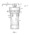
- FIG. 1 illustrates a side view of a microwave digestion vessel including a pressure relieving valve assembly;
- FIG. 2 illustrates a cross-section of the vessel and valve assembly;
- FIG. 3 illustrates an enlarged view of a portion of the valve assembly;
- FIG. 4 illustrates a partial cutaway top view of the vessel;
- FIG. 5 illustrates a bottom view of the vessel;
- FIG. 6 illustrates vessels used in a microwave oven during a microwave digestion procedure;
- FIG. 7 illustrates a first alternative embodiment side view of a microwave digestion vessel including pressure relief valve;
- FIG. 8 illustrates a top view of alternate embodiment 7;
- FIG. 9 illustrates an exploded view in cross section of an alternate embodiment;
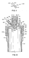
- FIG. 10 illustrates a cross-section side view of FIG. 7 taken along line 9-9 of FIG. 7; and
- FIG. 11 illustrates an alternate embodiment of an alternative structure of a hydrophobic vent insert.
- FIG. 1 illustrates a side view of a
microwave digestion vessel 10 including a TeflonPFA vessel 12 with a threaded top 13, as illustrated in FIG. 2, and amolding flange 14 for encompassing a lower portion of a TeflonPFA cap 16 withinternal threads 18, as illustrated in FIG. 2. Avalve body 20 extends upwardly from the top of thecap 16, and is described in detail in FIG. 2. Aventing tube 54 extends outwardly from thevalve cap 46 as later described. Aretaining ring 22 with a top leadingedge 24 surrounds an upper portion of thecap 16 and includesinternal threads 26 as illustrated in FIG. 2. Thering 22 provides thatcap 16 cannot expand away from thevessel 12 during microwave digestion procedures at elevated temperatures.Threads 26 are self threading providing for loose screwing of thering 22 on and off of thecap 16 as required. - FIG. 2 illustrates a cross-sectional view of FIG. 1 where all numerals correspond to those elements previously described. Particularly, the
valve body 20 includes acentral hole 28, aball seat 30, andnarrow aperture clearance 32 upwardly extending on an interior section of an upwardly extendingvalve body wall 27. The ball seat is positioned about a lower portion of aball 34 in the top wall of thecap 16. Top 36 of thevalve body 20 is planar providing for a positive stop. TheTeflon ball 34 engages against theball seat 30. ATeflon spiral spring 38 engages within the internalcylindrical wall section 39 of thevalve body 20. TheTeflon spring 38 includes two opencylindrical members spiral spring 44. A plurality ofspacing nipples 45a-45n extend outwardly from the members 40-44. Eachcylindrical member valve cap 46 includesinterior threads 48 which engage withthreads 29 of thevalve body 47, providing for an integral fit. Atop underside surface 47 ofvalve cap 46 is also planar providing for a positive stop and mating with the planar surface 36 ofvalve body 20. A hole 50 extends upwardly to a side hole 52 for venting of pressures out the side of thevalve cap 46. Arelief tube 54 can be pressed into the side hole 50 for relieving and draining residual fluids into a second container as later described. The Teflon spring can be glass filled, a composite, or the like, for maintaining a proper flexible spring coefficient. The vessel bottom, vessel cap, and valve seat and cap, as well as the ball and spring can also be made out of other materials than Teflon PFA. The spring section can also assume any other like geometrical configuration such as a "Z" shape, etc., rather than the spiral shape as illustrated. Thering 22 can be of a polymer, a composite, or other like material. Theflange 14 is of an annular right angle shape so that the lower portion of thecap 16 screws and extends down into the area created by the encompassing annular flange so that thecap 16 will not expand off of the threaded vessel top 13 during digestion processes which create height pressures. The top of thevessel 12 includes a flat planar lip edge s0 with annularexterior edge 64. The interior of thecap 12 includes an angled annularinterior wedge edge 62. As thecap 16 is screwed on tightly,angled wedge edge 62 exerts outward force uponlip edge 60 and forces it and theannular exterior edge 64 outwardly affecting a secure pressurized seal betweenedge 64 and the adjacent interior cap surface, as well as betweenwedge edge 62 and portions oflip edge 60. It is illustrated that the twoplanar surfaces 36 and 47 ofvalve body 20 andvalve cap 46, respectively, mate flush with each other's surfaces. - FIG. 3 illustrates an enlarged view of the
valve body 27,ball 34, and thespring 38. Each opencylindrical member flat surface Hollow portions members spring 38 is interchangeable in either direction for ease of installation. The spring includes a plurality ofspacing nipples 45a-45n for spacing elements 40-44 from theside wall 39. The spring can be of one to ten turns, while two turns are illustrated by way of example and for purposes of illustration only. The transition from theball seat 30 to the clearance of each side of the 34 inhole 28 is in the range of 20/1000 inch for controlling pressure release, although any other suitable dimension can be utilized as parameters would require. - FIG. 4 illustrates a top view in partial cross section of the present invention where all numerals correspond to those elements previously described. In this view, as well as the bottom view of FIG. 5, a plurality of downwardly extending
lugs 56a-56n are provided for thecap 16, and a plurality of like downwardly extendinglugs 58a-58n are provided for the thevessel 12. These ribs provide point contact gripping point for a lug tool to separate the top and bottom of the vessel. The lower lugs 58a-58n are molded into the lower edge offlange 14 for structural integrity and stability. - FIG. 5 illustrates a bottom view of the vessel where all numbers correspond to those elements previously described.
- FIG. 6 illustrates the mode of operation of the present invention, illustrating a
microwave oven 80, and aturntable 82 in themicrowave oven cavity 84 for supporting a plurality ofdigestion vessels 10 about the perimeter of theturntable 82. Twodigestion vessels container 90 positions on the axis of the turntable. The microwave digestion vessels include relief tubes from the hole of each valve assembly coupled into the container for discharge of any residual pressure, vapors, or liquids, etc. Thecontainer 90 can include acap 92. The container and cap can be made of Teflon, glass, or any other material transparent to microwave energy. - In operation, and referring particularly to FIGS. 2 and 3, when the pressure becomes high enough to overcome the spring coefficient, the
ball 34 is unseated off theball seat 30, and pressure flows around the circumference of the ball atclearance 32, up and around theopen cylinders spring section 44 as spaced by the spacing nipples 40a-40n. Gas exhausts through the top surface of thecylinder 42 and out through the vent holes 50 and 52 andtube 54. Thetube 54 channels the gas and vapors into thecontainer 90 as illustrated in FIG. 5 or the unit can be operated with a short tube exhausting to open air inside the oven or with no tube. Each vessel can be used without the retainingring 22 as so desired. The bottle, cap, and ring will be made of materials transparent to microwave energy. The material, while indicated as a fluoropolymer, such as Teflon PFA, can include a glass fiber filler, rag content, or a composite material. The ring can also be made of a polymer as required. The vessels can be used with or without the ring as illustrated in FIG. 5 where one vessel is illustrated with thering 22 and the other vessel is without the ring. - FIG. 7 illustrates a side view of a first alternate embodiment of a microwave digestion vessel 100 including a
vessel 102 of Teflon PFA or like material with a buttress threaded upper member lo4 as illustrated in FIG. 9. A moldedflange 106 encompasses a lower portion of a TeflonPFA vessel cap 108 including internal buttressthreads 110 as illustrated in FIG. 9, although the moldedflange 106 is not required for operation in low pressure functions. A threadedcap neck 112 extends from the upper surface of thecap 108.Cap 114 fits over and aboutneck 112. A configured, angled, threadedfilter body member 116 intersects with theneck 112 and the top surface of the cap orlid 108. Apointer member 118 positions on the upper surface ofcap 108 for determining and referencing preset adjustment of the relief internal valve as described in detail in FIGS. 9 and 10.Lugs 109a-109n and 111a-111n, as described in previous Figures position about 28 and oncap 108 andvessel 102 for tightening of thecap 108 to thevessel 102. Aknurled nut 120 with internal ferrels positions over and about the angledfilter tube body 116 for securing arelief tube 122 to thefilter body 116. - FIG. 8 illustrates a top view of the cap or
lid 108 including thesmaller cap 114, theadjustment reference numbers 124, thepointer 118 for referencingadjustment numbers 124, thefilter body 116, theknurled nut 120 and therelief tube 122. - FIG. 9 illustrates an exploded view of the relief valve and outlet port of FIG. 7. The inner
cylindrical portion 113 of threadedneck 112 and a semi-spherical cavityball seat surface 126 in a lower portion ofcap 108 form avalve cavity body 128. Asmall orifice 130 positions at the bottom of thevalve cavity 128 to vent pressure from the interior ofvessel 102 out throughfilter body tube 116 as described in later detail. Ahole 132 positions between thevent cavity 128 and alarger hole 134 in thefilter body 116 as illustrated. Bevelededge 136 at the outer portion oflarger hole 134 accommodates a built-inintegral ferrel surface 138 for positioning and securing arelief tube 122 to thefilter body 116. Ahydrophobic filter 140 at the end ofrelief tube 122 positions in the inner portion oflarger hole 134 to relieve gas pressures and exclude liquids from exiting overboard. Aspring cavity 142 is formed by walls ofcylindrical sleeve 144. A solidradiused end 146 integral to thesleeve 144 positions at the end of thesleeve 144 and acts to serve as a valve when placed intocavity 128 and againstvalve hole 130. Aspring 148 consisting of non-corrosive material such as being a spring coated with Teflon, a polymer material, a glass spring, a Teflon spring, or the like, positions inspring cavity 142 of thehollow sleeve 144. A threaded configuredcap 114 similar to those in previous figures positions over and about the threadedneck 112. The top of threadedneck 112 forms anannular seal 115 to mate with the annular grove 119 in the inner top ofcap 114. Thespring 148 in thehollow sleeve 144 exerts downward pressure against flat surface 145 to radiusedball valve 146, thereby affecting a pressure seal of theradiused ball valve 146 insemi-spherical cavity 126 surface and sealing against theorifice 130. Fine interior buttressed threads 15o mate to fine exterior buttressedthreads 152 of theneck 112 providing for vernier like fine adjustment of tension onspring 148, thereby allowing for fine tuning of the pressure relief differential as vessel pressures relieve throughorifice 130, againstvalve ball 146, throughhydroscopic filter 140 infilter body 116, and overboard throughrelief tube 122. The top ofvessel 102 forms anannular ring 103 and effects a seal inannular groove 105 incap 108 as illustrated. - FIG. 10 illustrates a cross-sectional assembled view of FIG. 9 where all numerals correspond to those elements previously described. Physical dimensions by way of example and not to be construed as limiting of the present invention include a 3/16" radius for the
semi-spherical ball seat 126, a 3/8"wide spring 148, a 3/64"sleeve 144 thickness, a 3/4"diameter cap 114, a 3/32" to 1/8"orifice 130, a 1/8"diameter orifice 132, 3/16" O.D. x 1/8" I.D.tubing 122, and a threaded diameter 0.600" buttress threaded GTPI 150 and 152. - FIG. 11 illustrates an alternative embodiment of structure for a
hydrophobic vent insert 200. Ahydrophobic vent insert 200 can in its entirety be placed withinhole 134 infilter body 116 in lieu ofhydrophobic filter 140. Configuredmale portion 202 mates into configuredfemale portion 204 as illustrated. A small wafer likehydrophobic filter 206 is placed internally as illustrated, and gases flow betweenorifices hydrophobic insert 200, and overboard throughvent tube 122. - During digestion in the vessel, the gas vents out during predigestion, allowing excess gas to escape without loosing any liquids inside the container. The adjustable nut allows for dialing in any predetermined pressure for different digestion procedures. A user can also open the adjustment nut before removing the main cap, allowing for the exhausting of any built-up pressure through the vent. The spring can be reused, or in the event that the spring has experienced fatigue, the spring can also be exchanged. The thin sleeve protects the spring from hot gases during a digestion procedure, as the gases vent in a least distance path, and does not pass by the spring. In the unlikely event that there is a spring failure, the gases will inherently pass between the orifices and not allow for build-up and dangerous pressures within the digestion vessel. The area for the porous plug or permeable membrane allows for gases to vent as safely as possible. The permeable membrane could be as thin as 10ml in any type of suitable microporous or filtering material. Of course, a two-piece assembly may also be utilized as illustrated in FIG. 11 for containing a thin disc or discs, such as for a hydrophobic vent. The springs can be made of any suitable materials, such as special alloys, Teflon coated, glass springs, glass-reinforced polymers, polymers or Teflon springs.
- Various modifications can be made to the present invention as being within the scope and teachings of the disclosure. The
hole 130 can be varied in diameter which would vary to release pressure at a desired level. Likewise, the spring compression is adjustable by the number of turns, diameter of the cross-section, etc., and any space between the top of the cap and the top of thesleeve 144 is adjustable. Thesleeve 144 is a one-piece member. During digestion, the sleeve rises to allow gases to escape, but not liquids under digestion, as indicated by dashed line "P" in FIG. 10. An external filter could be used in lieu of theassemblies
Claims (10)
1. A microwave heating digestion vessel for use in a microwave oven during a microwave heating digestion of a material comprising:
a. molded threaded vessel and mating molded threaded cap for covering said vessel, said vessel and said cap being transparent to microwave energy; and,
b. valve assembly affixed to the top of said cap, said valve assembly including a ball seat with a vent opening disposed in said cap, a first orifice extending from a mid portion of said cap and through said cap to a lower most portion of said valve seat, a second venting orifice extending from about said valve seat through said cap to vent to the atmosphere, a hollow cylindrical neck including a threaded outer portion extending upwardly from said cap about said valve seat, said cylindrical neck supporting a spring assembly therein, a hollow cylindrical member with a ball mate at a lower end, a flat positive annular stop surface at the top of said cylindrical stem, and a small cap including a threaded inner portion and a annular sealing, said threaded small cap covering said cylindrical stem and retaining said spring assembly, said spring assembly acting on and against surface opposite said ball mate.
2. The microwave heating digestion vessel of Claim 1 wherein said molded threaded vessel and cap are made of fluorocarbons.
3. The microwave heating digestion vessel of Claim 1 including an encompassing cylindrical flange extending upwardly from a mid portion of said vessel and encompassing said lower edge of said cap.
4. The microwave heating digestion vessel of Claim 1 wherein said spring assembly is made of fluorocarbons.
5. The microwave heating digestion vessel of Claim l wherein said spring assembly is of a composite material.
6. The microwave heating digestion vessel of Claim 1 wherein said spring section comprises 1-10 turns.
7. The digestion vessel of Claim 1 including member means on said cap and a pointer affixed to said cap for aligning said numbering means with said pointer for different pressure settings of said spring.
8. The microwave heating system vessel of Claim 1 wherein a spring protector sleeve extends over and about said spring.
9. The microwave heating digestion vessel of claim 1 wherein spring failure depressurizes said vessel.
10. A microwave heating digestion vessel for use in a microwave oven during a microwave heating digestion of a material comprising:
a. molded threaded vessel;
b. mating molded threaded cap for covering said vessel, said vessel and said cap being transparent to microwave energy;
c. valve assembly affixed to the top of said cap, said valve assembly including a ball seat with a vent opening disposed in said cap, a first orifice extending from a mid portion of said cap and through said cap to a lower most portion of said valve seat, a second venting orifice extending from about said valve seat through said cap to vent to the atmosphere, a hollow cylindrical neck including a threaded outer portion extending upwardly from said cap about said valve seat, said cylindrical neck supporting a spring assembly therein;
d. a hollow cylindrical member with a ball mate at a lower end, a flat positive annular stop surface at the top of said cylindrical stem;
e. a small cap including a threaded inner portion and a annular sealing, said threaded small cap covering said cylindrical stem and retaining said spring assembly, said spring assembly acting on and against surface opposite said ball mate; and,
f. pointer means on said large cap for aligning with dialed members on said small cap.
Applications Claiming Priority (1)
| Application Number | Priority Date | Filing Date | Title |
|---|---|---|---|
| US06/702,639 US4613738A (en) | 1985-02-19 | 1985-02-19 | Microwave heating digestion vessel |
Publications (1)
| Publication Number | Publication Date |
|---|---|
| EP0335020A1 true EP0335020A1 (en) | 1989-10-04 |
Family
ID=24822047
Family Applications (1)
| Application Number | Title | Priority Date | Filing Date |
|---|---|---|---|
| EP88302857A Withdrawn EP0335020A1 (en) | 1985-02-19 | 1988-03-30 | Microwave heating digestion vessell |
Country Status (2)
| Country | Link |
|---|---|
| US (1) | US4613738A (en) |
| EP (1) | EP0335020A1 (en) |
Cited By (7)
| Publication number | Priority date | Publication date | Assignee | Title |
|---|---|---|---|---|
| EP0427113A1 (en) * | 1989-10-31 | 1991-05-15 | Inwave Ag Industrie Mikrowellentechnik | Micro-wave oven with insert |
| EP0429814A2 (en) * | 1989-10-11 | 1991-06-05 | Mls Gmbh | Process and apparatus for initiating and/or promoting chemical processes |
| EP0467625A2 (en) * | 1990-07-19 | 1992-01-22 | CEM Corporation | Temperature controlled microwave system for heating contents of sealed moving containers |
| WO1993022650A2 (en) * | 1992-04-30 | 1993-11-11 | Mls Mikrowellen-Labor-Systeme Gmbh | Device for evaporating preferably liquid substances, in particular reagents, or for preparing or analyzing sampled materials |
| WO2000072957A1 (en) * | 1999-06-01 | 2000-12-07 | Cem Corporation | Sealing closure for high pressure vessels in microwave assisted chemistry |
| EP1547681A3 (en) * | 2003-09-02 | 2005-09-07 | CEM Corporation | Controlled flow instrument for microwave assisted chemical process |
| US7041947B2 (en) | 2003-09-02 | 2006-05-09 | Cem Corporation | Controlled flow instrument for microwave assisted chemistry with high viscosity liquids and heterogeneous mixtures |
Families Citing this family (34)
| Publication number | Priority date | Publication date | Assignee | Title |
|---|---|---|---|---|
| US4736083A (en) * | 1985-02-19 | 1988-04-05 | Savillex Corporation | Microwave heating digestion vessel |
| US4613738A (en) * | 1985-02-19 | 1986-09-23 | Savillex | Microwave heating digestion vessel |
| US4877624A (en) * | 1985-04-11 | 1989-10-31 | Cem Corporation | Digestion and sterilization methods and apparatus |
| US4882128A (en) * | 1987-07-31 | 1989-11-21 | Parr Instrument Company | Pressure and temperature reaction vessel, method, and apparatus |
| US4801773A (en) * | 1987-10-01 | 1989-01-31 | Ronnie Hanlon | Shroud to cover dish in microwave oven |
| DE3839901A1 (en) * | 1988-11-25 | 1990-05-31 | Werner Lautenschlaeger | SAMPLE CONTAINER TO UNLOCK SAMPLE MATERIAL |
| EP0382334A3 (en) * | 1989-02-09 | 1991-09-18 | Bio-Rad Laboratories, Inc. | Microwave method for preparation of serum samples for b-12 and folate assays |
| US5204065A (en) * | 1989-03-01 | 1993-04-20 | Terry Floyd | High pressure and high temperature digestion vessel |
| US5264185A (en) * | 1989-03-01 | 1993-11-23 | Floyd Terry S | High pressure and high temperature digestion vessel |
| US4904450A (en) * | 1989-03-01 | 1990-02-27 | Terry Floyd | High temperature and high pressure digestion vessel assembly |
| US4933529A (en) * | 1989-04-03 | 1990-06-12 | Savillex Corporation | Microwave heating digestion vessel |
| US5108701A (en) * | 1989-05-15 | 1992-04-28 | Cem Corporation | Process for rapid sterilization of biological media |
| US5320804A (en) * | 1989-05-15 | 1994-06-14 | Cem Corporation | Process and apparatus for controlled microwave heating under pressure |
| US5230865A (en) * | 1989-09-08 | 1993-07-27 | Cem Corporation | Ventable rupture diaphragm-protected container for heating contained materials by microwave radiation |
| US5206479A (en) * | 1990-05-04 | 1993-04-27 | Cem Corporation | Microwave heating system |
| US5407641A (en) * | 1990-10-25 | 1995-04-18 | Helmut Katschnig | Microwave apparatus, and container for use in a microwave apparatus |
| DE4108766C2 (en) * | 1991-03-18 | 1996-08-01 | Knapp Guenter Univ Prof Dipl I | Device for heating substances under high pressure in the microwave field |
| CA2093996C (en) * | 1992-05-04 | 2005-01-11 | Bobby Earl Green | Microwaveable squeeze bottle for cheese sauce and the like |
| US20020198230A1 (en) * | 1993-09-24 | 2002-12-26 | Howard M. Kingston | Method and apparatus for microwave assisted chemical reactions |
| DE4413425B4 (en) * | 1994-04-18 | 2006-08-31 | Anton Paar Gmbh | Device for monitoring the pressure in several digestion vessels |
| US5948307A (en) * | 1997-06-04 | 1999-09-07 | O.I. Corporation | High pressure relief for microwave digestion vessel assembly |
| US6803237B2 (en) | 2000-01-25 | 2004-10-12 | Woods Hole Oceanographic Institution | Sequential processing reaction vessel for chemical fractionation and analysis |
| JP3375930B2 (en) * | 2000-03-06 | 2003-02-10 | 日本ピラー工業株式会社 | Check valve |
| DE10050085C1 (en) * | 2000-10-10 | 2001-10-31 | Jochem Koetting | Container closure element e.g. for analysis or reaction tube, provided as sphere, sphere segment, section or layer with paramagnetic core |
| DE20120649U1 (en) * | 2001-12-20 | 2002-04-18 | Mikrowellen Labor Systeme | Device for closing a pot-shaped digestion container |
| US20030127313A1 (en) * | 2001-12-20 | 2003-07-10 | Milestone S.R.L. | Device for closing a pot-like digestion vessel |
| US20030194352A1 (en) * | 2001-12-20 | 2003-10-16 | Milestone S.R.L. | Device for closing a plurality of digestion vessesls |
| US7311118B2 (en) * | 2004-03-30 | 2007-12-25 | Parker-Hannifin Corporation | Floating ball check valve |
| US7820944B2 (en) * | 2006-05-08 | 2010-10-26 | Lincoln Global, Inc. | Spectroscopic technique for measuring the composition of cored wire electrodes |
| US20110086380A1 (en) * | 2008-04-10 | 2011-04-14 | Denator Aktiebolag | Device for storing a biological sample and for preparing the biological sample |
| ITRM20110140U1 (en) * | 2011-09-08 | 2013-03-09 | Etatron D S Spa | INJECTION VALVE EQUIPPED WITH SPRING IN PVDF PLASTIC MATERIAL, USED AS AN ACCESSORY OF ELECTROMECHANICAL DOSING PUMPS |
| CN104056584B (en) * | 2014-05-23 | 2016-03-02 | 上海屹尧仪器科技发展有限公司 | Be applicable to microwave operational environment from pressure-releasing type chemical reaction kettle |
| US10065168B2 (en) | 2016-05-02 | 2018-09-04 | Cem Corporation | High temperature pressure digestion vessel system with dual action seal |
| CN108709790B (en) * | 2018-05-02 | 2021-01-22 | 佛山市高明区杨和金属材料专业镇技术创新中心 | Exhaust device of microwave digestion instrument |
Citations (3)
| Publication number | Priority date | Publication date | Assignee | Title |
|---|---|---|---|---|
| FR2417045A1 (en) * | 1978-02-14 | 1979-09-07 | Accumulateurs Fixes | Internal pressure relief valve for electric accumulator - has triangular section plug with O=ring seal fitting in hole to be raised by excess internal pressure |
| US4490597A (en) * | 1979-09-19 | 1984-12-25 | Mengel Clare L | Microwave permeable pressure compensating container |
| US4613738A (en) * | 1985-02-19 | 1986-09-23 | Savillex | Microwave heating digestion vessel |
Family Cites Families (6)
| Publication number | Priority date | Publication date | Assignee | Title |
|---|---|---|---|---|
| US2226593A (en) * | 1940-12-31 | Pressure cooker | ||
| US2826218A (en) * | 1953-10-02 | 1958-03-11 | Sidney D Barlow | Valve construction |
| US4343325A (en) * | 1977-09-28 | 1982-08-10 | Draft Systems, Inc. | Valve assembly and coupler therefor |
| US4254319A (en) * | 1979-06-25 | 1981-03-03 | Bruce Beh | Portable microwave oven-turntable device |
| US4406861A (en) * | 1980-02-19 | 1983-09-27 | Beauvais Max P | Microwave canning apparatus |
| ZA812894B (en) * | 1980-05-13 | 1982-05-26 | Thorn Cascade Co Ltd | Appliance for making an aerated beverage and a cap for a bottle used therein |
-
1985
- 1985-02-19 US US06/702,639 patent/US4613738A/en not_active Expired - Fee Related
-
1988
- 1988-03-30 EP EP88302857A patent/EP0335020A1/en not_active Withdrawn
Patent Citations (3)
| Publication number | Priority date | Publication date | Assignee | Title |
|---|---|---|---|---|
| FR2417045A1 (en) * | 1978-02-14 | 1979-09-07 | Accumulateurs Fixes | Internal pressure relief valve for electric accumulator - has triangular section plug with O=ring seal fitting in hole to be raised by excess internal pressure |
| US4490597A (en) * | 1979-09-19 | 1984-12-25 | Mengel Clare L | Microwave permeable pressure compensating container |
| US4613738A (en) * | 1985-02-19 | 1986-09-23 | Savillex | Microwave heating digestion vessel |
Non-Patent Citations (1)
| Title |
|---|
| SOVIET INVENTIONS ILLUSTRATED * |
Cited By (15)
| Publication number | Priority date | Publication date | Assignee | Title |
|---|---|---|---|---|
| EP0429814A2 (en) * | 1989-10-11 | 1991-06-05 | Mls Gmbh | Process and apparatus for initiating and/or promoting chemical processes |
| EP0429814A3 (en) * | 1989-10-11 | 1991-10-16 | Mls Gmbh | Process and apparatus for initiating and/or promoting chemical processes |
| EP0427113A1 (en) * | 1989-10-31 | 1991-05-15 | Inwave Ag Industrie Mikrowellentechnik | Micro-wave oven with insert |
| EP0467625A2 (en) * | 1990-07-19 | 1992-01-22 | CEM Corporation | Temperature controlled microwave system for heating contents of sealed moving containers |
| EP0467625A3 (en) * | 1990-07-19 | 1992-08-05 | Cem Corporation | Temperature controlled microwave system for heating contents of sealed moving containers |
| WO1993022650A3 (en) * | 1992-04-30 | 1993-12-23 | Mikrowellen Labor Systeme | Device for evaporating preferably liquid substances, in particular reagents, or for preparing or analyzing sampled materials |
| WO1993022650A2 (en) * | 1992-04-30 | 1993-11-11 | Mls Mikrowellen-Labor-Systeme Gmbh | Device for evaporating preferably liquid substances, in particular reagents, or for preparing or analyzing sampled materials |
| US5447077A (en) * | 1992-04-30 | 1995-09-05 | Mls Mikrowellen-Labor-Systeme Gmbh | Device for the evaporation treatment of preferably liquid substances, in particular reagents, or for the preparation or analysis of sample material |
| WO2000072957A1 (en) * | 1999-06-01 | 2000-12-07 | Cem Corporation | Sealing closure for high pressure vessels in microwave assisted chemistry |
| US6287526B1 (en) | 1999-06-01 | 2001-09-11 | Cem Corporation | Sealing closure for high pressure vessels in microwave assisted chemistry |
| US6863871B2 (en) | 1999-06-01 | 2005-03-08 | Cem Corporation | Sealing closure for high pressure vessels in microwave assisted chemistry |
| EP1547681A3 (en) * | 2003-09-02 | 2005-09-07 | CEM Corporation | Controlled flow instrument for microwave assisted chemical process |
| US7041947B2 (en) | 2003-09-02 | 2006-05-09 | Cem Corporation | Controlled flow instrument for microwave assisted chemistry with high viscosity liquids and heterogeneous mixtures |
| US7109452B2 (en) | 2003-09-02 | 2006-09-19 | Cem Corporation | Controlled flow instrument for microwave assisted chemistry with high viscosity liquids and heterogeneous mixtures |
| US7214913B2 (en) | 2003-09-02 | 2007-05-08 | Cem, Corporation | Controlled flow instrument for microwave assisted chemistry with high viscosity liquids and heterogeneous mixtures |
Also Published As
| Publication number | Publication date |
|---|---|
| US4613738A (en) | 1986-09-23 |
Similar Documents
| Publication | Publication Date | Title |
|---|---|---|
| EP0335020A1 (en) | Microwave heating digestion vessell | |
| US4736083A (en) | Microwave heating digestion vessel | |
| US4933529A (en) | Microwave heating digestion vessel | |
| US5264185A (en) | High pressure and high temperature digestion vessel | |
| US4904450A (en) | High temperature and high pressure digestion vessel assembly | |
| US5204065A (en) | High pressure and high temperature digestion vessel | |
| US5353949A (en) | Vent filter assembly | |
| EP1608828B1 (en) | Unitary overpressure vent panel assembly | |
| US5270010A (en) | Sample holder for decomposition or analysis of sample materials | |
| JP2017200568A (en) | Pressure cooker with improved safety | |
| GB1564483A (en) | Pressure cookers | |
| KR100386001B1 (en) | Device to exhaust smoke generated in battery | |
| US4402828A (en) | Pressure filter vessel | |
| FI69959C (en) | LOCK | |
| EP0337677A3 (en) | Vent cap | |
| US6311715B1 (en) | Stacked rupture disk assembly | |
| DE60207698D1 (en) | FILTER CARTRIDGES FOR A FILTER ARRANGEMENT | |
| US5911332A (en) | HEPA filtered storage canisters | |
| US5948307A (en) | High pressure relief for microwave digestion vessel assembly | |
| CN102901663B (en) | Novel closed micro-wave diminishing pot | |
| CA1074464A (en) | Top closure for control rod drive for nuclear reactor | |
| JPH01274382A (en) | Microwave heating digester | |
| DK150423B (en) | TARGET ELEMENT WITH AIR DEPOLARIZATION | |
| KR100536639B1 (en) | A safety cap for the pressure release valve of a pressure cooker and a pressure cooker using the same | |
| US20030127311A1 (en) | Device for closing a pot-like digestion vessel |
Legal Events
| Date | Code | Title | Description |
|---|---|---|---|
| PUAI | Public reference made under article 153(3) epc to a published international application that has entered the european phase |
Free format text: ORIGINAL CODE: 0009012 |
|
| AK | Designated contracting states |
Kind code of ref document: A1 Designated state(s): DE FR GB |
|
| STAA | Information on the status of an ep patent application or granted ep patent |
Free format text: STATUS: THE APPLICATION IS DEEMED TO BE WITHDRAWN |
|
| 18D | Application deemed to be withdrawn |
Effective date: 19900405 |