EP0337567B1 - A coherent radar - Google Patents
A coherent radar Download PDFInfo
- Publication number
- EP0337567B1 EP0337567B1 EP89200893A EP89200893A EP0337567B1 EP 0337567 B1 EP0337567 B1 EP 0337567B1 EP 89200893 A EP89200893 A EP 89200893A EP 89200893 A EP89200893 A EP 89200893A EP 0337567 B1 EP0337567 B1 EP 0337567B1
- Authority
- EP
- European Patent Office
- Prior art keywords
- magnetron
- frequency
- signal
- pulse
- phase
- Prior art date
- Legal status (The legal status is an assumption and is not a legal conclusion. Google has not performed a legal analysis and makes no representation as to the accuracy of the status listed.)
- Expired - Lifetime
Links
- 230000001427 coherent effect Effects 0.000 title claims description 10
- 230000005540 biological transmission Effects 0.000 claims description 14
- 230000004913 activation Effects 0.000 claims description 4
- 230000010355 oscillation Effects 0.000 description 13
- 230000037452 priming Effects 0.000 description 7
- 230000007704 transition Effects 0.000 description 6
- 230000001960 triggered effect Effects 0.000 description 6
- 238000002347 injection Methods 0.000 description 4
- 239000007924 injection Substances 0.000 description 4
- 238000010586 diagram Methods 0.000 description 3
- 239000004020 conductor Substances 0.000 description 2
- 238000002592 echocardiography Methods 0.000 description 2
- 238000001914 filtration Methods 0.000 description 2
- 239000000243 solution Substances 0.000 description 2
- 238000005259 measurement Methods 0.000 description 1
- 238000000926 separation method Methods 0.000 description 1
Images

Classifications
-
- G—PHYSICS
- G01—MEASURING; TESTING
- G01S—RADIO DIRECTION-FINDING; RADIO NAVIGATION; DETERMINING DISTANCE OR VELOCITY BY USE OF RADIO WAVES; LOCATING OR PRESENCE-DETECTING BY USE OF THE REFLECTION OR RERADIATION OF RADIO WAVES; ANALOGOUS ARRANGEMENTS USING OTHER WAVES
- G01S7/00—Details of systems according to groups G01S13/00, G01S15/00, G01S17/00
- G01S7/02—Details of systems according to groups G01S13/00, G01S15/00, G01S17/00 of systems according to group G01S13/00
- G01S7/28—Details of pulse systems
- G01S7/285—Receivers
- G01S7/288—Coherent receivers
-
- G—PHYSICS
- G01—MEASURING; TESTING
- G01S—RADIO DIRECTION-FINDING; RADIO NAVIGATION; DETERMINING DISTANCE OR VELOCITY BY USE OF RADIO WAVES; LOCATING OR PRESENCE-DETECTING BY USE OF THE REFLECTION OR RERADIATION OF RADIO WAVES; ANALOGOUS ARRANGEMENTS USING OTHER WAVES
- G01S7/00—Details of systems according to groups G01S13/00, G01S15/00, G01S17/00
- G01S7/02—Details of systems according to groups G01S13/00, G01S15/00, G01S17/00 of systems according to group G01S13/00
- G01S7/28—Details of pulse systems
- G01S7/282—Transmitters
Definitions
- the invention relates to a coherent radar comprising a magnetron, a modulator for driving the magnetron for the generation and transmission of HF-pulses, a stable local oscillator for producing an intermediate frequency signal of a frequency corresponding to the difference between the frequency of the stable local oscillator and the frequency of the transmitted pulses by mixing the output signal of the stable local oscillator and echo pulses caused by the transmitted pulses and an intermediate frequency oscillator the output signal of which is led, together with the intermediate frequency signal obtained by the mixing, to a phase sensitive detector for detecting the echo pulses and producing a signal, which inter alia contains information about the mutual phase position between transmitted and received HF-signals, the modulator being time controlled with respect to the intermediate frequency oscillator in such manner that the front flank of the modulator pulse and thereby the magnetron pulse always appears in a predetermined phase position of the output signal of the intermediate frequency oscillator, while a phase stable signal is fed to the tuning cavities of the magnetron in a time interval before the triggering of the magnetron
- the signal produced at the output of the phase sensitive detector can be used, both within un-ambiguity distance and at ambiguity distances, to separate targets having different radial speeds relative to the radar station; for example for the purpose to suppress echoes from fixed objects and only indicate movable targets.
- the modulator and the intermediate frequency oscillator are mutually time controlled in such manner that the front flank of the modulator pulse and thereby the magnetron pulse always appears in a predetermined phase position of the output signal of the intermediate frequency oscillator, and furthermore a phase stable signal, suitably derived from the already present stable local oscillator, is fed to the tuning cavities of the magnetron in an interval before triggering of the magnetron, so called priming.
- a phase stable signal suitably derived from the already present stable local oscillator
- a drawback for the solution according to the Swedish patent 8400140-3 is that the magnetron oscillations are not phase locked during the whole magnetron pulse but the phase can be subject to drift during the pulse itself. This can result in poor MTI-performance, in particular for extended magnetron pulses, while the MTI -performance for short pulses can be relatively good.
- the object of the present invention is to modify a coherent radar of the kind as described in the opening paragraph, having priming control according to the Swedish patent 8400140-3, in such manner that it will have better MTI-performance both for short and extended radar pulses.
- the radar comprises means for varying the frequency of the said phase stable signal during the front flank of the magnetron pulse between a first and a second or final frequency, the first frequency being derived from the frequency of the stable local oscillator or the frequencies of said stable local oscillator and the intermediate frequency oscillator, the second frequency being derived from the frequencies of the stable local oscillator and the intermediate frequency oscillator, which second frequency substantially corresponds to the transmission frequency of the magnetron, a phase stable signal of the first frequency being fed to the tuning cavities of the magnetron in a time interval before the triggering of the magnetron and during the beginning of the building-up phase of the magnetron pulse and a phase stable signal of the second frequency being fed to the tuning cavities of the magnetron during the end of the building-up phase of the magnetron pulse and during the magnetron pulse.
- the frequency variation is made stepwise in at least one step by means of a switching device.
- a switching device which will result in a simple device which is easy to control, for example on time basis.
- the invention involves that phase locking to en external signal of the same frequency as the transmission frequency of the magnetron is made in at least two operation modes.
- the previously proposed priming control which is interupted when the oscillations in the magnetron have started but not reached their final amplitude, i.e. during the front flank of the magnetron pulse.
- the true phase locking to a signal of the same frequency as the transmission frequency of the magnetron takes place, which phase-lock signal is maintained during the magnetron pulse. Due to the fact that both the priming signal and the phase-lock signal are derived from continuously operating, stable oscillators the mutual phase relationship between the priming signal and the phase-lock signal will also be constant and the magnetron pulse will have phase continuity from pulse to pulse.
- phase of the magnetron oscillations will be more constant during the whole magnetron pulse, i.e. both at the beginning of the pulse and at the end of extended magnetron pulses, as compared with the case when the phase locking takes place in one operation mode.
- phase locking of a magnetron to an external signal of the same frequency as the transmission frequency of the magnetron is previously known per se.
- the magnetron is then operating, more like an amplifier than as a self oscillating device and in order to obtain an effective phase locking an appreciable power quantity of the external locking signal must be fed to the magnetron.
- the MTI-performance can be relatively good for extended magnetron pulses, while the MTI-performance for short pulses will be poor.
- the frequency variation is effected as one single stepwise variation by switching between two signals of different frequencies; a first signal of a first frequency fed to the magnetron before the magnetron is triggered, and a second signal of a second frequency equal to the final frequency, which is supplied during the front flank of the magnetron pulse before the magnetron oscillations have reached their full amplitude, a maximally simple device will be obtained if both frequencies are derived from the already present phase stable oscillators, namely the stable local oscillator and the intermediate frequency oscillator.
- the signal of the second frequency or the final frequency can be generated by a mixer, in which the output signal of the local oscillator, is mixed with the output signal of the intermediate frequency oscillator, while the signal of the first frequency is formed by the output signal from the local oscillator itself. Then the difference between the two frequencies fed to the tuning cavities of the magnetron during the front flank of the magnetron pulse will be equal to the intermediate frequency in the system.
- the signal of the first frequency can also be generated by a mixer.
- a signal derived from the local oscillator is mixed with a signal derived from the intermediate frequency oscillator via a converting stage, for example a frequency divider. Then the difference between the two frequencies fed to the tuning cavities of the magnetron during the front flank of the magnetron pulse will deviate from the intermediate frequency.
- Simple and accurate control of the switching device is obtained if the control is effected by the modulator or a control device for the modulator, if desired via a time delay, so that the activation of the switching device will have a given time relationship to the triggering moment of the magnetron.
- a magnetron MAG is driven with short voltage pulses from a modulator MOD and the generated HF-pulses are led via a circulator CIRC and a Transmitter-Receiver switch TR to an antenna ANT for the transmission of the pulses. Echo pulses from a reflecting object, caused by the transmitted radar pulses are received with the same antenna ANT and are led via the Transmitter-Receiver switch TR to a mixer B1, where they are combined with the output signal from a stable local oscillator STALO.
- the magnetron is adjusted to a fixed transmission frequency, for example by means of a mechanical locking device or by means of a stepping motor.
- the transmission frequency f MAG of the magnetron then differs a quantity equal to the selected nominal intermediate frequency f MFO from the stable local oscillator frequency f STALO .
- Echo pulses at an intermediate frequency f MF having the said nominal value f MFO are then obtained from the mixer B1.
- the intermediate frequency signal is amplified in an intermediate frequency amplifier MF and is then led to a phase sensitive detector D, which also receives the output signal from a continuously operating oscillator MFO.
- This oscillator operates at a frequency equal to the selected nominal intermediate frequency f MFO and from the phase detector D a signal V bip is obtained, which is called bipolar video because it can assume both a positive and a negative value.
- the bipolar video signal represents, besides the strength of the echo signal, also the mutual phase position between transmitted and received HF-signals. If the distance between the radar equipment and the reflecting object varies with time the bipolar video signal V bip will vary with a frequency depending upon the distance variation, namely such that the signal will run through a 360° sequence for each half wavelength of distance variation to the reflecting object.
- the bipolar signal is then subject to a filtering operation, for example in a MTI-filter which in principle is a highpassfilter, for suppressing echoes from fixed objects, or for speed separation at ambiguity distance.
- the oscillations of the magnetron are phase locked to a stable signal derived from the two stable oscillators STALO and MFO, more closely to a signal obtained from a mixer B2 to which the output signals of the said two oscillators are fed.
- This signal from the mixer B2 is fed to the tuning cavities of the magnetron via a first switch SW1 of make-and-brake type, a second switch SW2 possibly an amplifier AMP, and the circulator CIRC.
- the switch SW2 is controlled from a control unit PRF of the modulator MOD in such manner that it is normally open but will be closed just before the moment, when the magnetron is triggered, and it is then kept closed during the magnetron pulse.
- the phase locking is effected in two steps thereby that, before the triggering of the magnetron and during a first part of the build-up phase of the magnetron pulse, instead of the said output signal from the mixer B2, the output signal from the stable local oscillator STALO alone is fed to the tuning cavities of the magnetron.
- Switching between the two signals is effected by means of the switch SW1 which in one position 1 conveys the output signal from the oscillator STALO to the tuning cavities of the magnetron and in the second position 0 conveys the output signal from the mixer B2 to the said cavities.
- the switch SW1 is controlled from the control unit PRF of the modulator, possibly via a time delay DEL, in such manner that it before triggering of the magnetron assumes the first position 1 and is set to the second position 0 when the oscillations in the magnetron have started but not yet reached their final amplitude, i.e. during the front flank of the magnetron pulse.
- the modulator MOD is time controlled from the intermediate frequency oscillator MFO via the control device PRF in such manner that the front flank of the modulator pulse always coincides with a given phase position of the output signal of the intermediate frequency oscillator MFO, for example a zero transition in a given direction.
- the said control device PRF can consist of a counter for counting the number of positive or negative zero transitions in the output signal of the intermediate frequency oscillator and bringing each n:th zero transition to start the modulator.
- the pulse repetition frequency prf can be generated externally, as is shown in Figure 1 by the control conductor EXT prf to the control device PRF drawn in dashed line.
- the control device PRF can comprise an AND-gate receiving at one of its inputs the signal from the external prf-generator via the control conductor EXT prf . At a second input the gate can receive pulses representing zero transitions in the output signal of the intermediate frequency oscillator. The modulator and thereby the magnetron will then be started at the first zero transition in the given direction after reception of prf-signal from the external generator.
- f STALO f MAG - f MFO
- f MAG the transmission frequency of the magnetron
- f STALO and f MFO are the frequencies of the two stable oscillators STALO and MFO.
- This oscillating energy which has phase continuity from pulse to pulse because it is derived from a continuously operating stable oscillator, influences the phase of the self-oscillations which are built-up in the magnetron at the triggering of the same.
- f STALO the supply of energy of the said oscillator frequency
- f MFO f MAG .
- the oscillations of the magnetron which are already phase controlled by means of an external signal, are now phase locked to this signal of the frequency f MAG .
- the mixing product of the frequency f MAG has phase continuity from pulse to pulse, because it is derived from two continuously operating stable oscillators. By the phase locking in two steps the phase, as seen over the whole magnetron pulse, will be more constant than if it had been made in only one step.
- the level 0 indicates that the switch SW1 is set in the position 0, where the output signal of the mixer B2 is led to the cavities of the magnetron, and the level 1 that the switch SW1 is set in the position 1, where the output signal of the local oscillator STALO is led to the magnetron.
- the switch SW1 is set back to the position 0, which means that the supply of the output signal of the local oscillator to the cavities of the magnetron is interrupted and that instead the output signal of the mixer B2 is fed to the magnetron.
- the time moment t3 must appear after the time moment t2 when the magnetron starts.
- the time moment t3 must furthermore appear before the time moment t4 when the HF-oscillations have reached their final amplitude.
- the time moment t3 is very close to the moment t2, which is advantageous for the phase locking taking place by injecting the output signal of the mixer B2 into the cavities of the magnetron in the moment t3.
- the time moment t0 must appear before the time moment t2 and should for example not be later than the time moment t1.
- the switch SW2 is reset to the position 0 and the injection of the phase locking signal is interrupted.
- the time moment t5 appears after the moment when the magnetron pulse has ceased, which means that injection of phase locking signal is maintained during the whole magnetron pulse.
- Figure 3 shows an example of a circuit, in which the frequency difference between the transmitted frequency and the frequency supplied to the magnetron in the starting moment is not the same as the intermediate frequency in the system.
- a signal of the transmission frequency is obtained thereby that the output signal from the stable oscillator STALO is mixed in a mixer B2 with the output signal from the intermediate frequency oscillator MFO.
- the oscillator STALO is tuned to the difference between the tranmission frequency of the magnetron and the frequency of the intermediate frequency oscillator MFO and a mixing product from B2 then will have the transmission frequency of the magnetron, which is led to the magnetron in the position 0 of the switch SW1. This takes place immediately before the moment when the magnetron pulse has reached its final amplitude.
- the signal fed to the magnetron in the starting moment is in the example according to Figure 3 obtained from a mixer B3, where the signal from the mixer B2 is mixed with a signal of suitable frequency derived from the oscillator MFO via a frequency divider F div .
- the output signal from the frequency divider F div is in the shown example also used to control the control unit PRF.
- the phase difference between the signal from the oscillator MFO and the signal from the frequency divider F div must be equal from pulse to pulse when the modulator MOD is triggered. This can be ensured in a simple manner if division with an integer is used in the frequency divider F div , but other divisional factors are also possible.
- the modulator cannot be triggered at any selected zero transition in the output signal from the frequency divider F div .
- the activation of the switch SW2 can alternatively be effected on basis of a measurement of a magnetron value, as cathode voltage, cathode current or HF-envelope.
- Phase locking can also be effected in more than two steps or by using a frequency sweep during the front flank of the magnetron pulse.
- the transmission frequency of the magnetron can deviate somewhat from the final frequency of the injected locking signal provided that it is kept within the so called locking bandwidth relative to the injection frequency.
- the allowable deviation between the injection frequency and the own frequency of the magnetron is normally less than 1%.
Description
- The invention relates to a coherent radar comprising a magnetron, a modulator for driving the magnetron for the generation and transmission of HF-pulses, a stable local oscillator for producing an intermediate frequency signal of a frequency corresponding to the difference between the frequency of the stable local oscillator and the frequency of the transmitted pulses by mixing the output signal of the stable local oscillator and echo pulses caused by the transmitted pulses and an intermediate frequency oscillator the output signal of which is led, together with the intermediate frequency signal obtained by the mixing, to a phase sensitive detector for detecting the echo pulses and producing a signal, which inter alia contains information about the mutual phase position between transmitted and received HF-signals, the modulator being time controlled with respect to the intermediate frequency oscillator in such manner that the front flank of the modulator pulse and thereby the magnetron pulse always appears in a predetermined phase position of the output signal of the intermediate frequency oscillator, while a phase stable signal is fed to the tuning cavities of the magnetron in a time interval before the triggering of the magnetron and during the build-up phase of the magnetron pulse, i.e. during the front flank of the magnetron pulse. After a filtering operation the signal produced at the output of the phase sensitive detector can be used, both within un-ambiguity distance and at ambiguity distances, to separate targets having different radial speeds relative to the radar station; for example for the purpose to suppress echoes from fixed objects and only indicate movable targets.
- When a magnetron is used as HF-source in a coherent radar of this kind it is important that it can be brought to deliver oscillations having a fixed phase relationship to the mixing product of the signal from the intermediate frequency oscillator and the signal from the stable local oscillator from pulse to pulse.
- In previously proposed solution of this problem, described in the Swedish patent SE 8400140-3, the modulator and the intermediate frequency oscillator are mutually time controlled in such manner that the front flank of the modulator pulse and thereby the magnetron pulse always appears in a predetermined phase position of the output signal of the intermediate frequency oscillator, and furthermore a phase stable signal, suitably derived from the already present stable local oscillator, is fed to the tuning cavities of the magnetron in an interval before triggering of the magnetron, so called priming. Such priming involves that a given quantity of oscillating-energy is present in the cavities of the magnetron when the magnetron is triggered and starts to build-up own oscillations. This results in that the phase of these oscillations will be locked to the priming signal, which is derived form a continuously operating stable oscillator. Hereby phase continuity of the magnetron oscillations from pulse to pulse will be obtained.
- A drawback for the solution according to the Swedish patent 8400140-3 is that the magnetron oscillations are not phase locked during the whole magnetron pulse but the phase can be subject to drift during the pulse itself. This can result in poor MTI-performance, in particular for extended magnetron pulses, while the MTI -performance for short pulses can be relatively good.
- The object of the present invention is to modify a coherent radar of the kind as described in the opening paragraph, having priming control according to the Swedish patent 8400140-3, in such manner that it will have better MTI-performance both for short and extended radar pulses.
- According to the invention this is achieved thereby, that the radar comprises means for varying the frequency of the said phase stable signal during the front flank of the magnetron pulse between a first and a second or final frequency, the first frequency being derived from the frequency of the stable local oscillator or the frequencies of said stable local oscillator and the intermediate frequency oscillator, the second frequency being derived from the frequencies of the stable local oscillator and the intermediate frequency oscillator, which second frequency substantially corresponds to the transmission frequency of the magnetron, a phase stable signal of the first frequency being fed to the tuning cavities of the magnetron in a time interval before the triggering of the magnetron and during the beginning of the building-up phase of the magnetron pulse and a phase stable signal of the second frequency being fed to the tuning cavities of the magnetron during the end of the building-up phase of the magnetron pulse and during the magnetron pulse.
- Preferably the frequency variation is made stepwise in at least one step by means of a switching device. This will result in a simple device which is easy to control, for example on time basis.
- The invention involves that phase locking to en external signal of the same frequency as the transmission frequency of the magnetron is made in at least two operation modes. In first hand the previously proposed priming control, which is interupted when the oscillations in the magnetron have started but not reached their final amplitude, i.e. during the front flank of the magnetron pulse. In a final mode then the true phase locking to a signal of the same frequency as the transmission frequency of the magnetron takes place, which phase-lock signal is maintained during the magnetron pulse. Due to the fact that both the priming signal and the phase-lock signal are derived from continuously operating, stable oscillators the mutual phase relationship between the priming signal and the phase-lock signal will also be constant and the magnetron pulse will have phase continuity from pulse to pulse.
- By the fact that the phase locking takes place in at least two modes the phase of the magnetron oscillations will be more constant during the whole magnetron pulse, i.e. both at the beginning of the pulse and at the end of extended magnetron pulses, as compared with the case when the phase locking takes place in one operation mode.
- It is to be observed that phase locking of a magnetron to an external signal of the same frequency as the transmission frequency of the magnetron is previously known per se. The magnetron is then operating, more like an amplifier than as a self oscillating device and in order to obtain an effective phase locking an appreciable power quantity of the external locking signal must be fed to the magnetron. In spite of this it will take a certain time at the beginning of the magnetron pulse before the phase of the generated oscillations is stable. In this case the MTI-performance can be relatively good for extended magnetron pulses, while the MTI-performance for short pulses will be poor.
- If the frequency variation is effected as one single stepwise variation by switching between two signals of different frequencies; a first signal of a first frequency fed to the magnetron before the magnetron is triggered, and a second signal of a second frequency equal to the final frequency, which is supplied during the front flank of the magnetron pulse before the magnetron oscillations have reached their full amplitude, a maximally simple device will be obtained if both frequencies are derived from the already present phase stable oscillators, namely the stable local oscillator and the intermediate frequency oscillator.
- Suitably the signal of the second frequency or the final frequency can be generated by a mixer, in which the output signal of the local oscillator, is mixed with the output signal of the intermediate frequency oscillator, while the signal of the first frequency is formed by the output signal from the local oscillator itself. Then the difference between the two frequencies fed to the tuning cavities of the magnetron during the front flank of the magnetron pulse will be equal to the intermediate frequency in the system.
- In an alternative embodiment the signal of the first frequency can also be generated by a mixer. In this mixer a signal derived from the local oscillator is mixed with a signal derived from the intermediate frequency oscillator via a converting stage, for example a frequency divider. Then the difference between the two frequencies fed to the tuning cavities of the magnetron during the front flank of the magnetron pulse will deviate from the intermediate frequency.
- Simple and accurate control of the switching device is obtained if the control is effected by the modulator or a control device for the modulator, if desired via a time delay, so that the activation of the switching device will have a given time relationship to the triggering moment of the magnetron.
- The invention is illustrated by means of example with reference to the accompanying drawings, in whch
- Figure 1 shows a block diagram for a radar with a magnetron as HF-source according to the invention.
- Figure 2 shows some time diagrams for explaining the invention and
- Figure 3 shows a second embodiment of the invention.
- According to the Figure 1 a magnetron MAG is driven with short voltage pulses from a modulator MOD and the generated HF-pulses are led via a circulator CIRC and a Transmitter-Receiver switch TR to an antenna ANT for the transmission of the pulses. Echo pulses from a reflecting object, caused by the transmitted radar pulses are received with the same antenna ANT and are led via the Transmitter-Receiver switch TR to a mixer B₁, where they are combined with the output signal from a stable local oscillator STALO. The magnetron is adjusted to a fixed transmission frequency, for example by means of a mechanical locking device or by means of a stepping motor. The transmission frequency fMAG of the magnetron then differs a quantity equal to the selected nominal intermediate frequency fMFO from the stable local oscillator frequency fSTALO. Echo pulses at an intermediate frequency fMF having the said nominal value fMFO are then obtained from the mixer B₁. The intermediate frequency signal is amplified in an intermediate frequency amplifier MF and is then led to a phase sensitive detector D, which also receives the output signal from a continuously operating oscillator MFO. This oscillator operates at a frequency equal to the selected nominal intermediate frequency fMFO and from the phase detector D a signal Vbip is obtained, which is called bipolar video because it can assume both a positive and a negative value. The bipolar video signal represents, besides the strength of the echo signal, also the mutual phase position between transmitted and received HF-signals. If the distance between the radar equipment and the reflecting object varies with time the bipolar video signal Vbip will vary with a frequency depending upon the distance variation, namely such that the signal will run through a 360° sequence for each half wavelength of distance variation to the reflecting object. The bipolar signal is then subject to a filtering operation, for example in a MTI-filter which in principle is a highpassfilter, for suppressing echoes from fixed objects, or for speed separation at ambiguity distance.
- In order to ensure that the bipolar video signal Vbip actually will represent the mutual phase position between the transmitted and received signals the following steps are taken.
- In first hand the oscillations of the magnetron are phase locked to a stable signal derived from the two stable oscillators STALO and MFO, more closely to a signal obtained from a mixer B₂ to which the output signals of the said two oscillators are fed. This signal from the mixer B₂ is fed to the tuning cavities of the magnetron via a first switch SW₁ of make-and-brake type, a second switch SW₂ possibly an amplifier AMP, and the circulator CIRC. The switch SW₂ is controlled from a control unit PRF of the modulator MOD in such manner that it is normally open but will be closed just before the moment, when the magnetron is triggered, and it is then kept closed during the magnetron pulse. The phase locking is effected in two steps thereby that, before the triggering of the magnetron and during a first part of the build-up phase of the magnetron pulse, instead of the said output signal from the mixer B₂, the output signal from the stable local oscillator STALO alone is fed to the tuning cavities of the magnetron. Switching between the two signals is effected by means of the switch SW₁ which in one
position 1 conveys the output signal from the oscillator STALO to the tuning cavities of the magnetron and in thesecond position 0 conveys the output signal from the mixer B₂ to the said cavities. The switch SW₁ is controlled from the control unit PRF of the modulator, possibly via a time delay DEL, in such manner that it before triggering of the magnetron assumes thefirst position 1 and is set to thesecond position 0 when the oscillations in the magnetron have started but not yet reached their final amplitude, i.e. during the front flank of the magnetron pulse. - In second hand the modulator MOD is time controlled from the intermediate frequency oscillator MFO via the control device PRF in such manner that the front flank of the modulator pulse always coincides with a given phase position of the output signal of the intermediate frequency oscillator MFO, for example a zero transition in a given direction.
- In an example with internal generation of the pulse repetition frequency pfr the said control device PRF can consist of a counter for counting the number of positive or negative zero transitions in the output signal of the intermediate frequency oscillator and bringing each n:th zero transition to start the modulator. Alternatively the pulse repetition frequency prf can be generated externally, as is shown in Figure 1 by the control conductor EXTprf to the control device PRF drawn in dashed line. In this case the control device PRF can comprise an AND-gate receiving at one of its inputs the signal from the external prf-generator via the control conductor EXTprf. At a second input the gate can receive pulses representing zero transitions in the output signal of the intermediate frequency oscillator. The modulator and thereby the magnetron will then be started at the first zero transition in the given direction after reception of prf-signal from the external generator.
- The function is that in the interval immediately before the triggering of the magnetron a small portion of the output signal of the stable local oscillator STALO is fed to the cavities of the magnetron. Thus, when the magnetron is triggered a small quantity of oscillating energy of the frequency of the stable oscillator is present in the cavities of the magnetron. According to the foregoing this frequency can be written

where fMAG is the transmission frequency of the magnetron and fSTALO and fMFO are the frequencies of the two stable oscillators STALO and MFO. - This oscillating energy, which has phase continuity from pulse to pulse because it is derived from a continuously operating stable oscillator, influences the phase of the self-oscillations which are built-up in the magnetron at the triggering of the same. When the oscillations have reached a certain, relatively small amplitude the supply of energy of the said oscillator frequency fSTALO is interrupted and instead the mixing product from the mixer B₂ is fed to the cavities of the magnetron. One of the mixing products from the mixer B₂ is:

- The oscillations of the magnetron, which are already phase controlled by means of an external signal, are now phase locked to this signal of the frequency fMAG. Also the mixing product of the frequency fMAG has phase continuity from pulse to pulse, because it is derived from two continuously operating stable oscillators. By the phase locking in two steps the phase, as seen over the whole magnetron pulse, will be more constant than if it had been made in only one step.
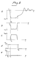
- The function is illustrated by means of the time diagrams in the Figure 2, where a) shows the voltage Vc from the modulator, which at the same time represents the cathode voltage of the magnetron as function of the time t, b) shows the cathode current IC as function of time, c) shows the envelope of the HF-voltage VHF, i.e. the generated magnetron pulse, Figure 2d) shows a control pulse V₂ fed to the switch SW₂ and e) shows a control pulse V₁ fed to the switch SW₁. In the Figure 2d) the
level 0 indicates that the switch SW₂ assumesposition 0, where it is open, and thelevel 1 that the switch assumesposition 1 where it is closed. In Figure 2e) thelevel 0 indicates that the switch SW₁ is set in theposition 0, where the output signal of the mixer B₂ is led to the cavities of the magnetron, and thelevel 1 that the switch SW₁ is set in theposition 1, where the output signal of the local oscillator STALO is led to the magnetron. - At the moment t₁ the voltage pulse Vc delivered by the modulator MOD to the cathode of the magnetron begins and the cathode voltage increases rapidly towards its final value. During the time interval t₁ to t₂ charging of the inner capacitances of the magnetron takes place. At the time moment t₂ immediately before the cathode voltage has reached its final value the magnetron will begin to generate HF-oscillations. At the moment t₀ lying before the moment t₁ both switches SW₂ and SW₁ are in the given example set in the
position 1. This means that in the interval before the triggering of the magnetron the output signal from the local oscillator STALO is fed to the cavities of the magnetron. At the time moment t₃ the switch SW₁ is set back to theposition 0, which means that the supply of the output signal of the local oscillator to the cavities of the magnetron is interrupted and that instead the output signal of the mixer B₂ is fed to the magnetron. The time moment t₃ must appear after the time moment t₂ when the magnetron starts. The time moment t₃ must furthermore appear before the time moment t₄ when the HF-oscillations have reached their final amplitude. In the given example the time moment t₃ is very close to the moment t₂, which is advantageous for the phase locking taking place by injecting the output signal of the mixer B₂ into the cavities of the magnetron in the moment t₃. The time moment t₀ must appear before the time moment t₂ and should for example not be later than the time moment t₁. At the time moment t₅ the switch SW₂ is reset to theposition 0 and the injection of the phase locking signal is interrupted. The time moment t₅ appears after the moment when the magnetron pulse has ceased, which means that injection of phase locking signal is maintained during the whole magnetron pulse. - Figure 3 shows an example of a circuit, in which the frequency difference between the transmitted frequency and the frequency supplied to the magnetron in the starting moment is not the same as the intermediate frequency in the system.
- In the same manner as in the first embodiment a signal of the transmission frequency is obtained thereby that the output signal from the stable oscillator STALO is mixed in a mixer B₂ with the output signal from the intermediate frequency oscillator MFO. The oscillator STALO is tuned to the difference between the tranmission frequency of the magnetron and the frequency of the intermediate frequency oscillator MFO and a mixing product from B₂ then will have the transmission frequency of the magnetron, which is led to the magnetron in the
position 0 of the switch SW₁. This takes place immediately before the moment when the magnetron pulse has reached its final amplitude. The signal fed to the magnetron in the starting moment is in the example according to Figure 3 obtained from a mixer B₃, where the signal from the mixer B₂ is mixed with a signal of suitable frequency derived from the oscillator MFO via a frequency divider Fdiv. The output signal from the frequency divider Fdiv is in the shown example also used to control the control unit PRF. For correct function of this system the phase difference between the signal from the oscillator MFO and the signal from the frequency divider Fdiv must be equal from pulse to pulse when the modulator MOD is triggered. This can be ensured in a simple manner if division with an integer is used in the frequency divider Fdiv, but other divisional factors are also possible. However, the modulator cannot be triggered at any selected zero transition in the output signal from the frequency divider Fdiv. - Instead of controlling the switch SW₂ on time basis by means of signal from the modulator or a control unit for the same the activation of the switch SW₂ can alternatively be effected on basis of a measurement of a magnetron value, as cathode voltage, cathode current or HF-envelope. Phase locking can also be effected in more than two steps or by using a frequency sweep during the front flank of the magnetron pulse. The transmission frequency of the magnetron can deviate somewhat from the final frequency of the injected locking signal provided that it is kept within the so called locking bandwidth relative to the injection frequency. The allowable deviation between the injection frequency and the own frequency of the magnetron is normally less than 1%.
Claims (6)
- A coherent radar comprising a magnetron (MAG), a modulator (MOD) for driving the magnetron for generation and transmission of HF-pulses, a stable local oscillator (STALO) for producing an intermediate frequency signal of a frequency corresponding to the difference between the frequency of the stable local oscillator (STALO) and the frequency of the transmitted pulses by mixing the output signal of the stable local oscillator (STALO) and echo pulses caused by the transmitted pulses, and an intermediate frequency oscillator (MFO) , the output signal of which is led, together with the intermediate frequency signal obtained by the mixing, to a phase sensitive detector (D) for detecting the echo pulses and producing a signal, which inter alia contains information about the mutual phase position between transmitted and received HF-signals, the modulator (MOD) being time controlled with respect to the intermediate frequency oscillator (MFO) in such manner that the front flank of the modulator pulse and thereby the magnetron pulse always appears in a predetermined phase position of the output signal of the intermediate frequency oscillator, while a phase stable signal is fed to the tuning cavities of the magnetron in a time interval before the triggering of the magnetron and during the build-up phase of the magnetron pulse, i.e. during the front flank of the magnetron pulse, characterized by means (SW₁, SW₂) for varying the frequency of the said phase stable signal during the front flank of the magnetron pulse between a first and a second or final frequency, the first frequency being derived from the frequency of the stable local oscillator (STALO) or the frequencies of said stable local oscillator (STALO) and the intermediate frequency oscillator (MFO), the second frequency being derived from the frequencies of the stable local oscillator and the intermediate frequency oscillator, which second frequency substantially corresponds to the transmission frequency of the magnetron (MAG), a phase stable signal of the first frequency being fed to the tuning cavities of the magnetron in a time interval before the triggering of the magnetron and during the beginning of the building-up phase of the magnetron pulse and a phase stable signal of the second frequency being fed to the tuning cavities of the magnetron during the end of the building-up phase of the magnetron pulse and during the magnetron pulse.
- A coherent radar as claimed in claim 1, characterized in that the frequency variation is made stepwise in at least one step by activation of a switching device (SW₁,SW₂).
- A coherent radar as claimed in any of the preceding claims, characterized in that the signal of the second frequency or the final frequency is generated by a mixer (B2), in which the output signal of the stable local oscillator (STALO) is mixed with the output signal of the intermediate frequency oscillator (MFO).
- A coherent radar as claimed in any of the preceding claims, characterized that the signal of the first frequency is the output signal from the the stable local oscillator (STALO) itself, whereby the difference between the two frequencies fed to the tuning cavities of the magnetron (MAG) during the front flank of the magnetron pulse will be equal to the frequency of the intermediate frequency signal.
- A coherent radar as claimed in any of the claims 1-3, characterized in that the first signal of the first frequency is generated by a mixer (B3), in which a signal derived from the stable local oscillator (STALO) is mixed with a signal derived from the intermediate frequency oscillator (MFO) via a converting stage (Fdiv), for example a frequency divider, whereby the difference between the two frequencies fed to the tuning cavities of the magnetron (MAG) during the front flank of the magnetron pulse, will deviate from the frequency of the intermediate frequency signal.
- A coherent radar as claimed in claim 2, characterized in that said switching device (SW₁,SW₂) is controlled from the modulator (MOD) or a control device (PRF) for the modulator, if desired via a time delay (DEL), so that its activation will have a given time relationship to the triggering moment of the magnetron (MAG).
Applications Claiming Priority (2)
| Application Number | Priority Date | Filing Date | Title |
|---|---|---|---|
| SE8801385 | 1988-04-14 | ||
| SE8801385A SE460805B (en) | 1988-04-14 | 1988-04-14 | COHERENT RADAR |
Publications (2)
| Publication Number | Publication Date |
|---|---|
| EP0337567A1 EP0337567A1 (en) | 1989-10-18 |
| EP0337567B1 true EP0337567B1 (en) | 1993-11-24 |
Family
ID=20372012
Family Applications (1)
| Application Number | Title | Priority Date | Filing Date |
|---|---|---|---|
| EP89200893A Expired - Lifetime EP0337567B1 (en) | 1988-04-14 | 1989-04-10 | A coherent radar |
Country Status (5)
| Country | Link |
|---|---|
| US (1) | US4935744A (en) |
| EP (1) | EP0337567B1 (en) |
| CN (1) | CN1052953A (en) |
| DE (1) | DE68910862D1 (en) |
| SE (1) | SE460805B (en) |
Cited By (35)
| Publication number | Priority date | Publication date | Assignee | Title |
|---|---|---|---|---|
| US7926975B2 (en) | 2007-12-21 | 2011-04-19 | Altair Engineering, Inc. | Light distribution using a light emitting diode assembly |
| US7938562B2 (en) | 2008-10-24 | 2011-05-10 | Altair Engineering, Inc. | Lighting including integral communication apparatus |
| US7946729B2 (en) | 2008-07-31 | 2011-05-24 | Altair Engineering, Inc. | Fluorescent tube replacement having longitudinally oriented LEDs |
| US7976196B2 (en) | 2008-07-09 | 2011-07-12 | Altair Engineering, Inc. | Method of forming LED-based light and resulting LED-based light |
| US8118447B2 (en) | 2007-12-20 | 2012-02-21 | Altair Engineering, Inc. | LED lighting apparatus with swivel connection |
| US8214084B2 (en) | 2008-10-24 | 2012-07-03 | Ilumisys, Inc. | Integration of LED lighting with building controls |
| US8256924B2 (en) | 2008-09-15 | 2012-09-04 | Ilumisys, Inc. | LED-based light having rapidly oscillating LEDs |
| US8299695B2 (en) | 2009-06-02 | 2012-10-30 | Ilumisys, Inc. | Screw-in LED bulb comprising a base having outwardly projecting nodes |
| US8324817B2 (en) | 2008-10-24 | 2012-12-04 | Ilumisys, Inc. | Light and light sensor |
| US8330381B2 (en) | 2009-05-14 | 2012-12-11 | Ilumisys, Inc. | Electronic circuit for DC conversion of fluorescent lighting ballast |
| US8360599B2 (en) | 2008-05-23 | 2013-01-29 | Ilumisys, Inc. | Electric shock resistant L.E.D. based light |
| US8362710B2 (en) | 2009-01-21 | 2013-01-29 | Ilumisys, Inc. | Direct AC-to-DC converter for passive component minimization and universal operation of LED arrays |
| US8421366B2 (en) | 2009-06-23 | 2013-04-16 | Ilumisys, Inc. | Illumination device including LEDs and a switching power control system |
| US8444292B2 (en) | 2008-10-24 | 2013-05-21 | Ilumisys, Inc. | End cap substitute for LED-based tube replacement light |
| US8454193B2 (en) | 2010-07-08 | 2013-06-04 | Ilumisys, Inc. | Independent modules for LED fluorescent light tube replacement |
| US8523394B2 (en) | 2010-10-29 | 2013-09-03 | Ilumisys, Inc. | Mechanisms for reducing risk of shock during installation of light tube |
| US8541958B2 (en) | 2010-03-26 | 2013-09-24 | Ilumisys, Inc. | LED light with thermoelectric generator |
| US8540401B2 (en) | 2010-03-26 | 2013-09-24 | Ilumisys, Inc. | LED bulb with internal heat dissipating structures |
| US8556452B2 (en) | 2009-01-15 | 2013-10-15 | Ilumisys, Inc. | LED lens |
| US8596813B2 (en) | 2010-07-12 | 2013-12-03 | Ilumisys, Inc. | Circuit board mount for LED light tube |
| US8653984B2 (en) | 2008-10-24 | 2014-02-18 | Ilumisys, Inc. | Integration of LED lighting control with emergency notification systems |
| US8664880B2 (en) | 2009-01-21 | 2014-03-04 | Ilumisys, Inc. | Ballast/line detection circuit for fluorescent replacement lamps |
| US8674626B2 (en) | 2008-09-02 | 2014-03-18 | Ilumisys, Inc. | LED lamp failure alerting system |
| US8870415B2 (en) | 2010-12-09 | 2014-10-28 | Ilumisys, Inc. | LED fluorescent tube replacement light with reduced shock hazard |
| US8901823B2 (en) | 2008-10-24 | 2014-12-02 | Ilumisys, Inc. | Light and light sensor |
| US9057493B2 (en) | 2010-03-26 | 2015-06-16 | Ilumisys, Inc. | LED light tube with dual sided light distribution |
| US9072171B2 (en) | 2011-08-24 | 2015-06-30 | Ilumisys, Inc. | Circuit board mount for LED light |
| US9163794B2 (en) | 2012-07-06 | 2015-10-20 | Ilumisys, Inc. | Power supply assembly for LED-based light tube |
| US9184518B2 (en) | 2012-03-02 | 2015-11-10 | Ilumisys, Inc. | Electrical connector header for an LED-based light |
| US9271367B2 (en) | 2012-07-09 | 2016-02-23 | Ilumisys, Inc. | System and method for controlling operation of an LED-based light |
| US9267650B2 (en) | 2013-10-09 | 2016-02-23 | Ilumisys, Inc. | Lens for an LED-based light |
| US9285084B2 (en) | 2013-03-14 | 2016-03-15 | Ilumisys, Inc. | Diffusers for LED-based lights |
| US9510400B2 (en) | 2014-05-13 | 2016-11-29 | Ilumisys, Inc. | User input systems for an LED-based light |
| US9574717B2 (en) | 2014-01-22 | 2017-02-21 | Ilumisys, Inc. | LED-based light with addressed LEDs |
| US10161568B2 (en) | 2015-06-01 | 2018-12-25 | Ilumisys, Inc. | LED-based light with canted outer walls |
Families Citing this family (8)
| Publication number | Priority date | Publication date | Assignee | Title |
|---|---|---|---|---|
| GB2444299B (en) | 2006-11-30 | 2011-07-27 | Secr Defence | Weather radar signal processing |
| CN102540262B (en) * | 2010-12-27 | 2013-10-30 | 中国电子科技集团公司第五十研究所 | Nonlinear node detector |
| JP5963573B2 (en) * | 2012-06-29 | 2016-08-03 | 古野電気株式会社 | Radar equipment |
| RU2503972C1 (en) * | 2012-08-07 | 2014-01-10 | Закрытое акционерное общество "Комплексный технический сервис" | Coherent-pulse radar set |
| CN103412311A (en) * | 2013-07-15 | 2013-11-27 | 陕西兴源电子设备有限公司 | Pulse digitalized radar |
| RU2710363C1 (en) * | 2019-07-10 | 2019-12-26 | Акционерное общество "Центральный научно-исследовательский радиотехнический институт имени академика А.И. Берга" | Onboard detector with compensation for variations of magnetic fields |
| JP7297619B2 (en) * | 2019-09-18 | 2023-06-26 | 株式会社東芝 | rangefinder |
| CN111913154B (en) * | 2020-08-14 | 2021-09-14 | 成都亘波雷达科技有限公司 | Magnetron radar receiving phase parameter word processing method |
Family Cites Families (8)
| Publication number | Priority date | Publication date | Assignee | Title |
|---|---|---|---|---|
| US2586028A (en) * | 1945-02-28 | 1952-02-19 | Grayson Harry | Radio echo moving target indicator |
| US2977589A (en) * | 1954-09-18 | 1961-03-28 | Csf | Electromagnetic detecting and tracking devices |
| US2901707A (en) * | 1956-10-19 | 1959-08-25 | Sanders Associates Inc | Coherent-pulsed oscillator |
| US3020539A (en) * | 1958-03-24 | 1962-02-06 | Maxson Electronics Corp | Modulated carrier wave moving target detection radar system |
| US4072944A (en) * | 1967-03-29 | 1978-02-07 | Sanders Associates, Inc. | Imminent collision detection apparatus |
| GB1468546A (en) * | 1974-07-11 | 1977-03-30 | Marconi Co Ltd | Pulsed doppler radar systems |
| US4079378A (en) * | 1977-02-28 | 1978-03-14 | General Dynamics Corporation | Coherent pulse radar system with time-shared frequency source |
| SE440958B (en) * | 1984-01-12 | 1985-08-26 | Philips Norden Ab | COHERENT RADAR |
-
1988
- 1988-04-14 SE SE8801385A patent/SE460805B/en not_active IP Right Cessation
-
1989
- 1989-04-10 EP EP89200893A patent/EP0337567B1/en not_active Expired - Lifetime
- 1989-04-10 US US07/335,915 patent/US4935744A/en not_active Expired - Fee Related
- 1989-04-10 DE DE89200893T patent/DE68910862D1/en not_active Expired - Lifetime
- 1989-04-11 CN CN89102320.8A patent/CN1052953A/en active Pending
Cited By (54)
| Publication number | Priority date | Publication date | Assignee | Title |
|---|---|---|---|---|
| US8118447B2 (en) | 2007-12-20 | 2012-02-21 | Altair Engineering, Inc. | LED lighting apparatus with swivel connection |
| US8928025B2 (en) | 2007-12-20 | 2015-01-06 | Ilumisys, Inc. | LED lighting apparatus with swivel connection |
| US7926975B2 (en) | 2007-12-21 | 2011-04-19 | Altair Engineering, Inc. | Light distribution using a light emitting diode assembly |
| US8360599B2 (en) | 2008-05-23 | 2013-01-29 | Ilumisys, Inc. | Electric shock resistant L.E.D. based light |
| US8807785B2 (en) | 2008-05-23 | 2014-08-19 | Ilumisys, Inc. | Electric shock resistant L.E.D. based light |
| US7976196B2 (en) | 2008-07-09 | 2011-07-12 | Altair Engineering, Inc. | Method of forming LED-based light and resulting LED-based light |
| US7946729B2 (en) | 2008-07-31 | 2011-05-24 | Altair Engineering, Inc. | Fluorescent tube replacement having longitudinally oriented LEDs |
| US8674626B2 (en) | 2008-09-02 | 2014-03-18 | Ilumisys, Inc. | LED lamp failure alerting system |
| US8256924B2 (en) | 2008-09-15 | 2012-09-04 | Ilumisys, Inc. | LED-based light having rapidly oscillating LEDs |
| US8444292B2 (en) | 2008-10-24 | 2013-05-21 | Ilumisys, Inc. | End cap substitute for LED-based tube replacement light |
| US9101026B2 (en) | 2008-10-24 | 2015-08-04 | Ilumisys, Inc. | Integration of LED lighting with building controls |
| US8324817B2 (en) | 2008-10-24 | 2012-12-04 | Ilumisys, Inc. | Light and light sensor |
| US8901823B2 (en) | 2008-10-24 | 2014-12-02 | Ilumisys, Inc. | Light and light sensor |
| US9585216B2 (en) | 2008-10-24 | 2017-02-28 | Ilumisys, Inc. | Integration of LED lighting with building controls |
| US9398661B2 (en) | 2008-10-24 | 2016-07-19 | Ilumisys, Inc. | Light and light sensor |
| US9635727B2 (en) | 2008-10-24 | 2017-04-25 | Ilumisys, Inc. | Light and light sensor |
| US10342086B2 (en) | 2008-10-24 | 2019-07-02 | Ilumisys, Inc. | Integration of LED lighting with building controls |
| US10036549B2 (en) | 2008-10-24 | 2018-07-31 | Ilumisys, Inc. | Lighting including integral communication apparatus |
| US9353939B2 (en) | 2008-10-24 | 2016-05-31 | iLumisys, Inc | Lighting including integral communication apparatus |
| US7938562B2 (en) | 2008-10-24 | 2011-05-10 | Altair Engineering, Inc. | Lighting including integral communication apparatus |
| US10176689B2 (en) | 2008-10-24 | 2019-01-08 | Ilumisys, Inc. | Integration of led lighting control with emergency notification systems |
| US8653984B2 (en) | 2008-10-24 | 2014-02-18 | Ilumisys, Inc. | Integration of LED lighting control with emergency notification systems |
| US10182480B2 (en) | 2008-10-24 | 2019-01-15 | Ilumisys, Inc. | Light and light sensor |
| US8251544B2 (en) | 2008-10-24 | 2012-08-28 | Ilumisys, Inc. | Lighting including integral communication apparatus |
| US8214084B2 (en) | 2008-10-24 | 2012-07-03 | Ilumisys, Inc. | Integration of LED lighting with building controls |
| US8946996B2 (en) | 2008-10-24 | 2015-02-03 | Ilumisys, Inc. | Light and light sensor |
| US8556452B2 (en) | 2009-01-15 | 2013-10-15 | Ilumisys, Inc. | LED lens |
| US8664880B2 (en) | 2009-01-21 | 2014-03-04 | Ilumisys, Inc. | Ballast/line detection circuit for fluorescent replacement lamps |
| US8362710B2 (en) | 2009-01-21 | 2013-01-29 | Ilumisys, Inc. | Direct AC-to-DC converter for passive component minimization and universal operation of LED arrays |
| US8330381B2 (en) | 2009-05-14 | 2012-12-11 | Ilumisys, Inc. | Electronic circuit for DC conversion of fluorescent lighting ballast |
| US8299695B2 (en) | 2009-06-02 | 2012-10-30 | Ilumisys, Inc. | Screw-in LED bulb comprising a base having outwardly projecting nodes |
| US8421366B2 (en) | 2009-06-23 | 2013-04-16 | Ilumisys, Inc. | Illumination device including LEDs and a switching power control system |
| US8840282B2 (en) | 2010-03-26 | 2014-09-23 | Ilumisys, Inc. | LED bulb with internal heat dissipating structures |
| US9013119B2 (en) | 2010-03-26 | 2015-04-21 | Ilumisys, Inc. | LED light with thermoelectric generator |
| US9057493B2 (en) | 2010-03-26 | 2015-06-16 | Ilumisys, Inc. | LED light tube with dual sided light distribution |
| US8540401B2 (en) | 2010-03-26 | 2013-09-24 | Ilumisys, Inc. | LED bulb with internal heat dissipating structures |
| US8541958B2 (en) | 2010-03-26 | 2013-09-24 | Ilumisys, Inc. | LED light with thermoelectric generator |
| US9395075B2 (en) | 2010-03-26 | 2016-07-19 | Ilumisys, Inc. | LED bulb for incandescent bulb replacement with internal heat dissipating structures |
| US8454193B2 (en) | 2010-07-08 | 2013-06-04 | Ilumisys, Inc. | Independent modules for LED fluorescent light tube replacement |
| US8596813B2 (en) | 2010-07-12 | 2013-12-03 | Ilumisys, Inc. | Circuit board mount for LED light tube |
| US8894430B2 (en) | 2010-10-29 | 2014-11-25 | Ilumisys, Inc. | Mechanisms for reducing risk of shock during installation of light tube |
| US8523394B2 (en) | 2010-10-29 | 2013-09-03 | Ilumisys, Inc. | Mechanisms for reducing risk of shock during installation of light tube |
| US8870415B2 (en) | 2010-12-09 | 2014-10-28 | Ilumisys, Inc. | LED fluorescent tube replacement light with reduced shock hazard |
| US9072171B2 (en) | 2011-08-24 | 2015-06-30 | Ilumisys, Inc. | Circuit board mount for LED light |
| US9184518B2 (en) | 2012-03-02 | 2015-11-10 | Ilumisys, Inc. | Electrical connector header for an LED-based light |
| US9163794B2 (en) | 2012-07-06 | 2015-10-20 | Ilumisys, Inc. | Power supply assembly for LED-based light tube |
| US9807842B2 (en) | 2012-07-09 | 2017-10-31 | Ilumisys, Inc. | System and method for controlling operation of an LED-based light |
| US9271367B2 (en) | 2012-07-09 | 2016-02-23 | Ilumisys, Inc. | System and method for controlling operation of an LED-based light |
| US9285084B2 (en) | 2013-03-14 | 2016-03-15 | Ilumisys, Inc. | Diffusers for LED-based lights |
| US9267650B2 (en) | 2013-10-09 | 2016-02-23 | Ilumisys, Inc. | Lens for an LED-based light |
| US9574717B2 (en) | 2014-01-22 | 2017-02-21 | Ilumisys, Inc. | LED-based light with addressed LEDs |
| US10260686B2 (en) | 2014-01-22 | 2019-04-16 | Ilumisys, Inc. | LED-based light with addressed LEDs |
| US9510400B2 (en) | 2014-05-13 | 2016-11-29 | Ilumisys, Inc. | User input systems for an LED-based light |
| US10161568B2 (en) | 2015-06-01 | 2018-12-25 | Ilumisys, Inc. | LED-based light with canted outer walls |
Also Published As
| Publication number | Publication date |
|---|---|
| SE8801385L (en) | 1989-10-15 |
| EP0337567A1 (en) | 1989-10-18 |
| CN1052953A (en) | 1991-07-10 |
| US4935744A (en) | 1990-06-19 |
| DE68910862D1 (en) | 1994-01-05 |
| SE460805B (en) | 1989-11-20 |
| SE8801385D0 (en) | 1988-04-14 |
Similar Documents
| Publication | Publication Date | Title |
|---|---|---|
| EP0337567B1 (en) | A coherent radar | |
| US4427982A (en) | Radar clutter reduction by use of frequency-diverse, wideband pulse-compression waveforms | |
| EP0499706B1 (en) | A transmitting and receiving part of a pulse doppler radar | |
| US4338604A (en) | Pulsed coherent doppler radar with frequency agility | |
| US4095224A (en) | Digital phase correction for coherent-on-receive pulsed radar system | |
| US5019825A (en) | Coherently interruptible frequency hopped chirp generator | |
| US4682178A (en) | HF arrangement | |
| US4021804A (en) | Synchronized, coherent timing system for coherent-on-receive radar system | |
| US6914556B1 (en) | Method and apparatus for magnetron coherence | |
| JP2644849B2 (en) | FM-CW radar device | |
| US3358282A (en) | Device for generating high frequency pulses having a predetermined frequency by means of a continuously tunable magnetron | |
| AU4313289A (en) | Coherent radar with recirculating fiber-optic delay line | |
| CN115800996A (en) | Phase-locked loop, radio frequency signal transmitter, radar sensor and electronic equipment | |
| GB1487439A (en) | Pulse radar apparatus | |
| US2977589A (en) | Electromagnetic detecting and tracking devices | |
| US2659076A (en) | Moving object radio pulse-echo system | |
| EP0276885B1 (en) | A radar system | |
| US3339197A (en) | Pulsed radar system | |
| US2659077A (en) | Moving target radio pulse echo system | |
| JPH06109833A (en) | Chirp-pulse compression and tracking radar apparatus | |
| US2617983A (en) | Moving target detecting system | |
| US3900799A (en) | Split pulse generator | |
| US3369233A (en) | Wideband coherent frequency modulator with dynamic offset | |
| CN85101915A (en) | High-frequency device | |
| GB1468546A (en) | Pulsed doppler radar systems |
Legal Events
| Date | Code | Title | Description |
|---|---|---|---|
| PUAI | Public reference made under article 153(3) epc to a published international application that has entered the european phase |
Free format text: ORIGINAL CODE: 0009012 |
|
| AK | Designated contracting states |
Kind code of ref document: A1 Designated state(s): DE FR GB SE |
|
| 17P | Request for examination filed |
Effective date: 19900417 |
|
| RAP1 | Party data changed (applicant data changed or rights of an application transferred) |
Owner name: NOBELTECH ELECTRONICS AB |
|
| 17Q | First examination report despatched |
Effective date: 19900609 |
|
| GRAA | (expected) grant |
Free format text: ORIGINAL CODE: 0009210 |
|
| AK | Designated contracting states |
Kind code of ref document: B1 Designated state(s): DE FR GB SE |
|
| PG25 | Lapsed in a contracting state [announced via postgrant information from national office to epo] |
Ref country code: SE Effective date: 19931124 Ref country code: FR Effective date: 19931124 Ref country code: DE Effective date: 19931124 |
|
| REF | Corresponds to: |
Ref document number: 68910862 Country of ref document: DE Date of ref document: 19940105 |
|
| PG25 | Lapsed in a contracting state [announced via postgrant information from national office to epo] |
Ref country code: GB Effective date: 19940410 |
|
| EN | Fr: translation not filed | ||
| PLBE | No opposition filed within time limit |
Free format text: ORIGINAL CODE: 0009261 |
|
| STAA | Information on the status of an ep patent application or granted ep patent |
Free format text: STATUS: NO OPPOSITION FILED WITHIN TIME LIMIT |
|
| 26N | No opposition filed | ||
| GBPC | Gb: european patent ceased through non-payment of renewal fee |
Effective date: 19940410 |