EP0337663A2 - Filter and bleed valve therefor - Google Patents
Filter and bleed valve therefor Download PDFInfo
- Publication number
- EP0337663A2 EP0337663A2 EP89303409A EP89303409A EP0337663A2 EP 0337663 A2 EP0337663 A2 EP 0337663A2 EP 89303409 A EP89303409 A EP 89303409A EP 89303409 A EP89303409 A EP 89303409A EP 0337663 A2 EP0337663 A2 EP 0337663A2
- Authority
- EP
- European Patent Office
- Prior art keywords
- filter
- cap
- bore
- valve
- stem
- Prior art date
- Legal status (The legal status is an assumption and is not a legal conclusion. Google has not performed a legal analysis and makes no representation as to the accuracy of the status listed.)
- Ceased
Links
- 238000001914 filtration Methods 0.000 claims abstract description 23
- 230000007704 transition Effects 0.000 claims description 12
- 230000013011 mating Effects 0.000 claims description 10
- 239000007788 liquid Substances 0.000 claims description 9
- 238000007789 sealing Methods 0.000 claims description 8
- 238000004891 communication Methods 0.000 claims description 3
- 230000007423 decrease Effects 0.000 claims description 2
- 239000000706 filtrate Substances 0.000 claims description 2
- 239000007789 gas Substances 0.000 description 17
- 239000004033 plastic Substances 0.000 description 4
- 229920003023 plastic Polymers 0.000 description 4
- 239000000463 material Substances 0.000 description 3
- 238000011109 contamination Methods 0.000 description 2
- 239000012528 membrane Substances 0.000 description 2
- 238000000034 method Methods 0.000 description 2
- 239000002991 molded plastic Substances 0.000 description 2
- 239000011295 pitch Substances 0.000 description 2
- 239000000126 substance Substances 0.000 description 2
- 230000002411 adverse Effects 0.000 description 1
- 238000010276 construction Methods 0.000 description 1
- 230000000694 effects Effects 0.000 description 1
- 238000012986 modification Methods 0.000 description 1
- 230000004048 modification Effects 0.000 description 1
- 239000004417 polycarbonate Substances 0.000 description 1
- 229920000515 polycarbonate Polymers 0.000 description 1
- 238000003466 welding Methods 0.000 description 1
Images

Classifications
-
- B—PERFORMING OPERATIONS; TRANSPORTING
- B01—PHYSICAL OR CHEMICAL PROCESSES OR APPARATUS IN GENERAL
- B01D—SEPARATION
- B01D29/00—Filters with filtering elements stationary during filtration, e.g. pressure or suction filters, not covered by groups B01D24/00 - B01D27/00; Filtering elements therefor
- B01D29/39—Filters with filtering elements stationary during filtration, e.g. pressure or suction filters, not covered by groups B01D24/00 - B01D27/00; Filtering elements therefor with hollow discs side by side on, or around, one or more tubes, e.g. of the leaf type
- B01D29/41—Filters with filtering elements stationary during filtration, e.g. pressure or suction filters, not covered by groups B01D24/00 - B01D27/00; Filtering elements therefor with hollow discs side by side on, or around, one or more tubes, e.g. of the leaf type mounted transversely on the tube
-
- B—PERFORMING OPERATIONS; TRANSPORTING
- B01—PHYSICAL OR CHEMICAL PROCESSES OR APPARATUS IN GENERAL
- B01D—SEPARATION
- B01D19/00—Degasification of liquids
- B01D19/0031—Degasification of liquids by filtration
-
- B—PERFORMING OPERATIONS; TRANSPORTING
- B01—PHYSICAL OR CHEMICAL PROCESSES OR APPARATUS IN GENERAL
- B01D—SEPARATION
- B01D36/00—Filter circuits or combinations of filters with other separating devices
- B01D36/001—Filters in combination with devices for the removal of gas, air purge systems
Definitions
- the present invention relates to filtration and more particularly to a filter for filtering substances from a pure or colloidal solution under pressure.
- a problem associated with filtering a solution under pressure is that if trapped air or gas is present in the filtering chamber, this can substantially reduce or block the flow through the filter unit.
- the prior art has attempted to provide features which can remove trapped air from the filtering chamber. These methods have usually been limited to simply allowing air to escape in an uncontrolled manner.
- the solution to be filtered is under pressure, this can result in the solution to be filtered squirting out of the chamber, causing a mess and potential contamination of the surrounding area and possibly affecting the results of the filtering process being conducted.
- a valve for releasing trapped air or gas from a filter for filtering a pressurised solution comprising a neck portion for communication with the filter for escape of air or gas therefrom, valve means in the neck portion, and a cap mounted for angular movement on the neck to move the valve means so as to control the escape of air or gas from the filter.
- the invention thus comprises a bleed valve for releasing trapped gas from within the filter chamber. It is a principal advantage of this invention that the bleed valve releases trapped air or gas from the filter chamber in a controlled manner.
- the bleed valve may include a stem secured to the filter having a bore therethrough for communication with the filter chamber and a cap for controlling the release of trapped gas within the filter chamber.
- the cap may have a plunger with a contact surface which mates with a portion of the inside surface of the stem bore and an extension which fits within a narrow portion of the bore. Further features are given in the claims.
- the invention enables gas or air trapped in the filter chamber to be released in a controlled manner, which guards against the solution squirting out of the chamber, contamination of the surrounding area and adverse effects on the filtration.
- the filter assembly 10 is designed to filter liquids under pressure up to about 65 psi (450 kN/m2), generally in the range from 10 to 25 psi (69 to 173 kN/m2) and can be disposed of after a single use.
- the filter assembly 10 comprises a plastics housing 12 formed by a moulded plastics upper portion 13 and a moulded plastics lower portion 15, which are sealed together by ultrasonic welding to form a filtering chamber 14 within.
- such filter units are disposable filter units designed for single use.
- the upper and lower portions 13, 15 may be made of any desired plastics material. In the embodiment illustrated, the portions 13, 15 are made of a polycarbonate.
- the housing 12 has an inlet port 16 integrally formed therein having a passage 26 which communicates with the filter chamber 14.
- the housing 12 further comprises an outlet port 19 for removing the liquid after it has been filtered.
- Filter means 17 for filtering a liquid entering the filtering chamber are provided within the chamber 14.
- the filter means 17 comprise a plurality of support disks 18 each having a flat filtering membrane 20 disposed on each side of the support disk 18 for filtering a liquid.
- the disks 18 each have a passageway therein, for receiving the filtrate which is filtered by the membrane 20, which communicates with a common passage 19′, which in turn communicates with the outlet port 19.
- the details of construction of the filter means 17 and may be found in concurrent co-pending U.S. Application Serial No. 181,417 and the European application which claims priority therefrom. However, any other suitable filter means may be used for filtering the liquid within the filter chamber 14.
- a bleed valve assembly 22 is provided in the housing 12 for removing trapped gas from within the filter chamber 14.
- the bleed valve assembly 22 comprises a stem member 24 which extends outwardly away from the housing 12.
- the stem 24 is formed integrally with the housing 12.
- the stem 24 has a passage or bore 26 which extends therethrough.
- the outer end 30 of the bore 26 communicates with the outside environment, such as the atmosphere, and the inner end 31 of the bore 26 communicates with the filtering chamber 14.
- the bore 26 has a longitudinal first section 27 of a preselected length L1 and diameter D1.
- the diameter D1 is substantially constant along the length L1.
- a transition or second section 34 is provided adjacent the inner end of the first longitudinal section 27, where the diameter of the bore 26 substantially decreases along the length L2 of the transition section 34.
- a mating surface 35 is disposed at an angle ⁇ of about 30 ⁇ with respect to the longitudinal axis A of the bore 26.
- this mating surface 35 may be disposed at any desired angle ⁇ capable of providing a seal.
- the bore 26 adjacent the inner end of the transition section 34 is provided with a narrow substantially cylindrical section 36 having a diameter D2 and a length L3.
- a recess 38 is conveniently provided a recess 38 at the inner end of the narrow cylindrical section 36. However, the recess 38 may be omitted if so desired.
- a plastics bleed cap 40 is provided for engagement with the exterior portion of the stem member 24.
- the cap 40 is made of a more pliable material than the stem 24.
- the exterior of the stem 24 is provided with threads 41 which mate with corresponding threads 42 in the inner surface of the bleed cap 40. When the bleed cap 40 is angularly moved in one direction or in the opposite direction, this will cause the cap 40 to move vertically up or down respectively.
- the threads 41, 42 are of a pitch and size which allow easy passage of a gas therethrough.
- the bleed cap 40 is provided with a plunger 43 which extends within the bore 26 for controlling the flow of trapped air from within the chamber 14 to the external environment, typically the atmosphere.
- the plunger 43 has a first longitudinal section 44 which terminates in an annular contact tip section 46 which is designed to mate with the mating surface 35 of the transition section 34 of the stem member 24.
- the longitudinal section 44 of the plunger 43 has a cross-sectional area sufficiently smaller than the longitudinal section 27 of the bore 26 to allow gas to flow easily in the space between the plunger 43 and the edge of the bore 26.
- the annular contact tip section 46 preferably has a curved configuration so as to provide sealing engagement when pressed against the mating surface 35 of the transition section 34 of the stem member 24.
- the plunger 43 has such a length that the upper inside surface 47 of the cap 40 does not engage the outer end 49 of the stem 24.
- a cylindrical extension 48 of length L4 is provided, which is designed to extend into the narrow cylindrical section 36 of the stem 24.
- the length L4 of the extension 48 is such that, during rotation of the cap 40, a portion of the extension 48 will still remain within the cylindrical section 36 so as to allow controlled escape of trapped air.
- L4 may be about 0.19 cm (0.075 ⁇ ).
- the cylindrical extension 48 is designed to have a diameter D4 only slightly less than the inside diameter D3 of the narrow cylindrical section 36 of the stem 24.
- the diameter D1 may be approximately 0.14 cm (0.055 ⁇ ) and the diameter D2 may be approximately 0.11 cm (0.045 ⁇ ).
- the contact tip section 46 engages the transition section 34, of the stem member 24 so as to provide an annular seal between the transition section 34 and the tip section 46 to prevent any air and/or liquid from escaping from within the pressurized chamber 14.
- the cap 40 is simply rotated in the appropriate direction so as to cause upward vertical movement of the cap 40, thereby causing the plunger 43 to move out of engagement with the transition section 34.
- trapped air or gas will be allowed to escape in a controlled manner from the space between the plunger 43 and surrounding parts of the inner surface of the bore 26, upwards past the exterior end of the bore 26 and past the threaded sections of the cap 40 and the stem 24.
- the pitches of threads 41, 42 are such that vertical movement of the plunger 43is relatively slow, preferably such that the extension 48 will not leave the narrow section 36 in less than 1/4 rotation of the cap 40 and, preferably, in not less than 1/2 rotation.
- the rate of escape of trapped gas is relatively slow and therefore can be controlled quite easily by rotation of cap the 40.
- the cap 40 and the housing 12 are generally made of a clear or translucent plastics material, the rate at which trapped gas escapes can be carefully controlled and, if necessary, the bleed cap 40 can be closed to prevent or minimize any escape of liquid from within the chamber 14. Additionally, since the sealing portions of the cap 40 and the stem 24 are distinct from the extension 48, repeated opening and closing of the cap 40 will not substantially affect the ability to control the rate of escape of trapped gases.
Landscapes
- Chemical & Material Sciences (AREA)
- Chemical Kinetics & Catalysis (AREA)
- Filtration Of Liquid (AREA)
- Containers And Packaging Bodies Having A Special Means To Remove Contents (AREA)
- Self-Closing Valves And Venting Or Aerating Valves (AREA)
- Fluid-Damping Devices (AREA)
- Details Of Valves (AREA)
Abstract
Description
- The present invention relates to filtration and more particularly to a filter for filtering substances from a pure or colloidal solution under pressure.
- A problem associated with filtering a solution under pressure is that if trapped air or gas is present in the filtering chamber, this can substantially reduce or block the flow through the filter unit. In some instances, the prior art has attempted to provide features which can remove trapped air from the filtering chamber. These methods have usually been limited to simply allowing air to escape in an uncontrolled manner. However, since the solution to be filtered is under pressure, this can result in the solution to be filtered squirting out of the chamber, causing a mess and potential contamination of the surrounding area and possibly affecting the results of the filtering process being conducted.
- Therefore it is an important object of this invention to remove trapped air or gas efficiently from within the filter chamber of a filter for filtering substances from a pure or colloidal solution under pressure.
- According to the invention there is provided a valve for releasing trapped air or gas from a filter for filtering a pressurised solution, comprising a neck portion for communication with the filter for escape of air or gas therefrom, valve means in the neck portion, and a cap mounted for angular movement on the neck to move the valve means so as to control the escape of air or gas from the filter. The invention thus comprises a bleed valve for releasing trapped gas from within the filter chamber. It is a principal advantage of this invention that the bleed valve releases trapped air or gas from the filter chamber in a controlled manner. The bleed valve may include a stem secured to the filter having a bore therethrough for communication with the filter chamber and a cap for controlling the release of trapped gas within the filter chamber. The cap may have a plunger with a contact surface which mates with a portion of the inside surface of the stem bore and an extension which fits within a narrow portion of the bore. Further features are given in the claims. The invention enables gas or air trapped in the filter chamber to be released in a controlled manner, which guards against the solution squirting out of the chamber, contamination of the surrounding area and adverse effects on the filtration.
- An embodiment of the invention will be described by way of example, with reference to the drawings, in which:
- Figure 1 is a top plan view of a closed filter made in accordance with the present invention;
- Figure 2 is a front elevational view of the filter of Figure 1;
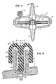
- Figure 3 is a cross-sectional view of the filter of Figure 2 taken along the line 3-3; and
- Figure 4 is an enlarged sectional view of a portion of the filter of Figure 1 illustrating means for removing trapped gas from within the filtering chamber.
- Referring to Figures 1 to 4, there is illustrated a
filter assembly 10. Typically, thefilter assembly 10 is designed to filter liquids under pressure up to about 65 psi (450 kN/m²), generally in the range from 10 to 25 psi (69 to 173 kN/m²) and can be disposed of after a single use. Thefilter assembly 10 comprises aplastics housing 12 formed by a moulded plasticsupper portion 13 and a moulded plasticslower portion 15, which are sealed together by ultrasonic welding to form afiltering chamber 14 within. Typically, such filter units are disposable filter units designed for single use. The upper andlower portions portions housing 12 has aninlet port 16 integrally formed therein having apassage 26 which communicates with thefilter chamber 14. Thehousing 12 further comprises anoutlet port 19 for removing the liquid after it has been filtered. - Filter means 17 for filtering a liquid entering the filtering chamber are provided within the
chamber 14. In the embodiment illustrated, the filter means 17 comprise a plurality ofsupport disks 18 each having a flat filteringmembrane 20 disposed on each side of thesupport disk 18 for filtering a liquid. Thedisks 18 each have a passageway therein, for receiving the filtrate which is filtered by themembrane 20, which communicates with acommon passage 19′, which in turn communicates with theoutlet port 19. The details of construction of the filter means 17 and may be found in concurrent co-pending U.S. Application Serial No. 181,417 and the European application which claims priority therefrom. However, any other suitable filter means may be used for filtering the liquid within thefilter chamber 14. - A
bleed valve assembly 22 is provided in thehousing 12 for removing trapped gas from within thefilter chamber 14. Referring to Figure 4, there is illustrated an enlarged cross-sectional view of the bleedvalve assembly 22 made in accordance with the present invention. Thebleed valve assembly 22 comprises astem member 24 which extends outwardly away from thehousing 12. Preferably, thestem 24 is formed integrally with thehousing 12. Thestem 24 has a passage orbore 26 which extends therethrough. Theouter end 30 of thebore 26 communicates with the outside environment, such as the atmosphere, and theinner end 31 of thebore 26 communicates with thefiltering chamber 14. Thebore 26 has a longitudinal first section 27 of a preselected length L1 and diameter D1. Preferably, the diameter D1 is substantially constant along the length L1. A transition orsecond section 34 is provided adjacent the inner end of the first longitudinal section 27, where the diameter of thebore 26 substantially decreases along the length L2 of thetransition section 34. In the embodiment illustrated, amating surface 35 is disposed at an angle α of about 30È with respect to the longitudinal axis A of thebore 26. However, thismating surface 35 may be disposed at any desired angle α capable of providing a seal. Thebore 26 adjacent the inner end of thetransition section 34 is provided with a narrow substantiallycylindrical section 36 having a diameter D2 and a length L3. In the embodiment illustrated, arecess 38 is conveniently provided arecess 38 at the inner end of the narrowcylindrical section 36. However, therecess 38 may be omitted if so desired. - A plastics bleed
cap 40 is provided for engagement with the exterior portion of thestem member 24. Preferably thecap 40 is made of a more pliable material than thestem 24. In the embodiment illustrated, the exterior of thestem 24 is provided withthreads 41 which mate withcorresponding threads 42 in the inner surface of thebleed cap 40. When thebleed cap 40 is angularly moved in one direction or in the opposite direction, this will cause thecap 40 to move vertically up or down respectively. Thethreads bleed cap 40 is provided with aplunger 43 which extends within thebore 26 for controlling the flow of trapped air from within thechamber 14 to the external environment, typically the atmosphere. - The
plunger 43 has a firstlongitudinal section 44 which terminates in an annularcontact tip section 46 which is designed to mate with themating surface 35 of thetransition section 34 of thestem member 24. Thelongitudinal section 44 of theplunger 43 has a cross-sectional area sufficiently smaller than the longitudinal section 27 of thebore 26 to allow gas to flow easily in the space between theplunger 43 and the edge of thebore 26. The annularcontact tip section 46 preferably has a curved configuration so as to provide sealing engagement when pressed against themating surface 35 of thetransition section 34 of thestem member 24. Theplunger 43 has such a length that the upper insidesurface 47 of thecap 40 does not engage theouter end 49 of thestem 24. At the inner end of thecontact tip section 46, acylindrical extension 48 of length L4 is provided, which is designed to extend into the narrowcylindrical section 36 of thestem 24. The length L4 of theextension 48 is such that, during rotation of thecap 40, a portion of theextension 48 will still remain within thecylindrical section 36 so as to allow controlled escape of trapped air. L4 may be about 0.19 cm (0.075˝). Thecylindrical extension 48 is designed to have a diameter D4 only slightly less than the inside diameter D3 of the narrowcylindrical section 36 of thestem 24. The diameter D1 may be approximately 0.14 cm (0.055˝) and the diameter D2 may be approximately 0.11 cm (0.045˝). - When the
bleed cap 40 is tightly secured to thestem 24, thecontact tip section 46 engages thetransition section 34, of thestem member 24 so as to provide an annular seal between thetransition section 34 and thetip section 46 to prevent any air and/or liquid from escaping from within the pressurizedchamber 14. However, when it is desired to remove trapped air from within thefilter chamber 14, thecap 40 is simply rotated in the appropriate direction so as to cause upward vertical movement of thecap 40, thereby causing theplunger 43 to move out of engagement with thetransition section 34. As this occurs, trapped air or gas will be allowed to escape in a controlled manner from the space between theplunger 43 and surrounding parts of the inner surface of thebore 26, upwards past the exterior end of thebore 26 and past the threaded sections of thecap 40 and thestem 24. The pitches ofthreads extension 48 will not leave thenarrow section 36 in less than 1/4 rotation of thecap 40 and, preferably, in not less than 1/2 rotation. - Since the
extension 48 is close in diameter to the narrowcylindrical section 36, the rate of escape of trapped gas is relatively slow and therefore can be controlled quite easily by rotation of cap the 40. Further, since thecap 40 and thehousing 12 are generally made of a clear or translucent plastics material, the rate at which trapped gas escapes can be carefully controlled and, if necessary, thebleed cap 40 can be closed to prevent or minimize any escape of liquid from within thechamber 14. Additionally, since the sealing portions of thecap 40 and thestem 24 are distinct from theextension 48, repeated opening and closing of thecap 40 will not substantially affect the ability to control the rate of escape of trapped gases. - It is to be understood that various changes or modifications may be made without departing from the scope of the present invention. For example, but not by way of limitation, the shape and/or configuration of the
mating surface 35 and thecontact tip section 46 may be varied as desired, so long as a sealing relationship is formed therebetween. The scope of the present invention is defined by the following claims.
Claims (11)
a stem (24) on a filter housing (12), the stem having a bore (26) extending therethrough into a filter chamber (14) in the housing, the said bore having a first longitudinal section (27) which communicates with the surrounding environment, a transition section (34) having a cross-sectional shape which decreases in size along its length and a narrow section (36) which communicates with the filter chamber, the transition section having an annular mating sealing surface (35);
a bleed cap (40) having means (42) for engaging the stem, the cap having a central longitudinal plunger (43) which extends into the stem bore, the plunger having a first longitudinal section (44), an annular contact tip section (46) for mating with the annular mating sealing surface and a longitudinal inner end (48) capable of extending into the narrow section of the bore, the cap when tightly secured to the stem causing the contact annular tip section to seal matingly with the mating sealing surface of the transition section and, when the cap is loosened, causing the contact annular tip section to move away from the transition section to allow controlled escape to the exterior of air or gas trapped within the chamber.
Applications Claiming Priority (2)
| Application Number | Priority Date | Filing Date | Title |
|---|---|---|---|
| US181416 | 1988-04-14 | ||
| US07/181,416 US4861466A (en) | 1988-04-14 | 1988-04-14 | Pressure filter assembly with bleed valve |
Publications (2)
| Publication Number | Publication Date |
|---|---|
| EP0337663A2 true EP0337663A2 (en) | 1989-10-18 |
| EP0337663A3 EP0337663A3 (en) | 1990-06-13 |
Family
ID=22664198
Family Applications (1)
| Application Number | Title | Priority Date | Filing Date |
|---|---|---|---|
| EP89303409A Ceased EP0337663A3 (en) | 1988-04-14 | 1989-04-06 | Filter and bleed valve therefor |
Country Status (3)
| Country | Link |
|---|---|
| US (1) | US4861466A (en) |
| EP (1) | EP0337663A3 (en) |
| JP (1) | JPH029403A (en) |
Cited By (3)
| Publication number | Priority date | Publication date | Assignee | Title |
|---|---|---|---|---|
| EP1101906A3 (en) * | 1999-11-20 | 2001-09-05 | IBS Filtran Kunststoff-/Metallerzeugnisse GmbH | Oil filter for engine or transmission |
| WO2002018037A2 (en) * | 2000-08-31 | 2002-03-07 | Millipore Corporation | Gas vent filter construction incorporating a hollow fiber membrane assembly |
| WO2002044529A1 (en) * | 2000-12-02 | 2002-06-06 | Ibs Filtran Kunststoff-/Metallerzeugnisse Gmbh | Suction oil filter for engines, gearboxes or automatic gear boxes |
Families Citing this family (9)
| Publication number | Priority date | Publication date | Assignee | Title |
|---|---|---|---|---|
| DE4321927C2 (en) * | 1993-07-01 | 1998-07-09 | Sartorius Gmbh | Filter unit with degassing device |
| US5634905A (en) * | 1996-02-14 | 1997-06-03 | W. L. Gore & Associates, Inc. | Apparatus for the prevention of retrograde movement of fluids during the use of air eliminating filters in intravenous therapy |
| KR0179284B1 (en) * | 1996-02-23 | 1999-03-20 | 문정환 | Bubble removing apparatus from filter housing of coating equipment |
| DE10111064B4 (en) * | 2001-03-08 | 2004-08-19 | Seitzschenk Filtersystems Gmbh | Filter module, installation kit for a filter module and filter device |
| US7794591B2 (en) | 2007-03-23 | 2010-09-14 | Zodiac Pool Systems, Inc. | Pool filter |
| AU2008251994B2 (en) * | 2007-10-05 | 2011-09-08 | Zodiac Pool Systems, Inc. | Methods and apparatus for a pool treatment and water system |
| US8516661B2 (en) * | 2009-04-29 | 2013-08-27 | Zodiac Pool Systems, Inc. | Retainer band for use in fluid-handling vessels |
| JP6191016B2 (en) | 2012-11-09 | 2017-09-06 | パナソニックIpマネジメント株式会社 | Semiconductor device |
| JP2015106656A (en) * | 2013-11-29 | 2015-06-08 | 東京エレクトロン株式会社 | Filter device |
Citations (4)
| Publication number | Priority date | Publication date | Assignee | Title |
|---|---|---|---|---|
| DE2148670A1 (en) * | 1970-09-30 | 1972-04-20 | Pall Corp | Disposable filters |
| US3701433A (en) * | 1970-11-10 | 1972-10-31 | Pall Corp | Filter for use in the filtration of blood |
| US3715863A (en) * | 1971-03-26 | 1973-02-13 | Bennett Pump Inc | Compact pump/air separator apparatus |
| FR2158213A1 (en) * | 1971-10-29 | 1973-06-15 | Sartorius Membranfilter Gmbh |
Family Cites Families (19)
| Publication number | Priority date | Publication date | Assignee | Title |
|---|---|---|---|---|
| US1467486A (en) * | 1921-06-24 | 1923-09-11 | Snow Mfg Company | Valve |
| US1535406A (en) * | 1923-01-29 | 1925-04-28 | George M Holley | Needle-valve retainer |
| US1546149A (en) * | 1924-05-01 | 1925-07-14 | James J Smith | Locking device for valve fittings |
| US1918959A (en) * | 1930-05-21 | 1933-07-18 | Ideal Lubricator Company | Adjustable valve |
| US1901971A (en) * | 1931-09-25 | 1933-03-21 | Adrian J Iorio | Fountain pen |
| US2983477A (en) * | 1956-04-19 | 1961-05-09 | M B Skinner Company | Plug valve saddle |
| US3255775A (en) * | 1962-10-08 | 1966-06-14 | Cabot Corp | Needle valve |
| US3484084A (en) * | 1967-07-07 | 1969-12-16 | Acf Ind Inc | Carburetor idle speed control |
| US3643917A (en) * | 1970-05-25 | 1972-02-22 | Shipston Engineering Co Ltd | Plastic drain cock |
| US3747894A (en) * | 1971-12-22 | 1973-07-24 | Genova Prod | Stop valve |
| US3912630A (en) * | 1972-10-24 | 1975-10-14 | Nordson Corp | Filter cartridge for thermoplastic applicator system |
| US4285498A (en) * | 1976-05-17 | 1981-08-25 | Imperial Chemical Industries Limited | Control valves |
| US4183500A (en) * | 1977-05-09 | 1980-01-15 | Imperial Chemical Industries Limited | Control valves |
| US4501663A (en) * | 1979-11-05 | 1985-02-26 | Millipore Corporation | Filter cartridges and methods and components for making them |
| US4276163A (en) * | 1979-11-13 | 1981-06-30 | Leonard Gordon | Hydrostatic relief valve |
| WO1981002616A1 (en) * | 1980-03-10 | 1981-09-17 | Corning Ltd | Safety locking arrangement |
| DD201387A1 (en) * | 1981-12-24 | 1983-07-20 | Siegfried Dreyer | FLAT MEMBRANE TRENNGERAET |
| DE3422979A1 (en) * | 1984-06-22 | 1986-01-02 | Robert Bosch Gmbh, 7000 Stuttgart | FILTER FOR DIESEL FUEL |
| IT8423859V0 (en) * | 1984-11-22 | 1984-11-22 | Macchi Ercole | VALVE GROUP STRUCTURE FOR STEAM IRON. |
-
1988
- 1988-04-14 US US07/181,416 patent/US4861466A/en not_active Expired - Fee Related
-
1989
- 1989-04-06 EP EP89303409A patent/EP0337663A3/en not_active Ceased
- 1989-04-12 JP JP1090879A patent/JPH029403A/en active Pending
Patent Citations (4)
| Publication number | Priority date | Publication date | Assignee | Title |
|---|---|---|---|---|
| DE2148670A1 (en) * | 1970-09-30 | 1972-04-20 | Pall Corp | Disposable filters |
| US3701433A (en) * | 1970-11-10 | 1972-10-31 | Pall Corp | Filter for use in the filtration of blood |
| US3715863A (en) * | 1971-03-26 | 1973-02-13 | Bennett Pump Inc | Compact pump/air separator apparatus |
| FR2158213A1 (en) * | 1971-10-29 | 1973-06-15 | Sartorius Membranfilter Gmbh |
Cited By (4)
| Publication number | Priority date | Publication date | Assignee | Title |
|---|---|---|---|---|
| EP1101906A3 (en) * | 1999-11-20 | 2001-09-05 | IBS Filtran Kunststoff-/Metallerzeugnisse GmbH | Oil filter for engine or transmission |
| WO2002018037A2 (en) * | 2000-08-31 | 2002-03-07 | Millipore Corporation | Gas vent filter construction incorporating a hollow fiber membrane assembly |
| WO2002018037A3 (en) * | 2000-08-31 | 2002-06-06 | Millipore Corp | Gas vent filter construction incorporating a hollow fiber membrane assembly |
| WO2002044529A1 (en) * | 2000-12-02 | 2002-06-06 | Ibs Filtran Kunststoff-/Metallerzeugnisse Gmbh | Suction oil filter for engines, gearboxes or automatic gear boxes |
Also Published As
| Publication number | Publication date |
|---|---|
| US4861466A (en) | 1989-08-29 |
| EP0337663A3 (en) | 1990-06-13 |
| JPH029403A (en) | 1990-01-12 |
Similar Documents
| Publication | Publication Date | Title |
|---|---|---|
| EP0337663A2 (en) | Filter and bleed valve therefor | |
| EP0325561B1 (en) | Apparatus for venting of gases from contact lens cases | |
| US4730635A (en) | Valve and method | |
| CA2421715C (en) | Self-sealing valve | |
| EP0022084A1 (en) | Device for vacuum sealing preserving jars used in the household | |
| US4301992A (en) | Diaphragm valve | |
| GB1482430A (en) | Closure arrangement | |
| US4168015A (en) | Tire inflation device | |
| EP0815915B1 (en) | Vacuum control valve for filtration device | |
| EP0247425A2 (en) | Flush device | |
| GB2076118A (en) | Injector device provided with a non-return valve | |
| KR860007149A (en) | Safety flow regulator | |
| US4679584A (en) | Soft seat Y-pattern check valve | |
| US3988001A (en) | Variable flow control valve for use with dental syringes and the like | |
| US4394921A (en) | Glassware stopper with venting valve | |
| DE2340389A1 (en) | SAMPLER | |
| US4708164A (en) | Safety relief valve | |
| US2679378A (en) | High-pressure valve | |
| US3993068A (en) | Piercing cannula of infusion and transfusion instruments | |
| US4728077A (en) | Drainage valve unit | |
| US5573031A (en) | Air bleed valve | |
| US4446883A (en) | End loaded valve | |
| US4637441A (en) | Inlet and outlet valves | |
| DE1293092B (en) | Auxiliary valve operated by gravity for a container with a riser pipe designed to dispense fluids under permanent pressure | |
| WO1983001669A1 (en) | Apparatus for discharging pressurised containers |
Legal Events
| Date | Code | Title | Description |
|---|---|---|---|
| PUAI | Public reference made under article 153(3) epc to a published international application that has entered the european phase |
Free format text: ORIGINAL CODE: 0009012 |
|
| AK | Designated contracting states |
Kind code of ref document: A2 Designated state(s): BE CH DE FR GB IT LI LU NL SE |
|
| PUAL | Search report despatched |
Free format text: ORIGINAL CODE: 0009013 |
|
| AK | Designated contracting states |
Kind code of ref document: A3 Designated state(s): BE CH DE FR GB IT LI LU NL SE |
|
| 17P | Request for examination filed |
Effective date: 19900808 |
|
| 17Q | First examination report despatched |
Effective date: 19911024 |
|
| STAA | Information on the status of an ep patent application or granted ep patent |
Free format text: STATUS: THE APPLICATION HAS BEEN REFUSED |
|
| 18R | Application refused |
Effective date: 19930731 |