EP0340922A1 - Bulk bin bag cassette - Google Patents
Bulk bin bag cassette Download PDFInfo
- Publication number
- EP0340922A1 EP0340922A1 EP89303487A EP89303487A EP0340922A1 EP 0340922 A1 EP0340922 A1 EP 0340922A1 EP 89303487 A EP89303487 A EP 89303487A EP 89303487 A EP89303487 A EP 89303487A EP 0340922 A1 EP0340922 A1 EP 0340922A1
- Authority
- EP
- European Patent Office
- Prior art keywords
- panel
- cassette
- diagonal
- side panels
- carton
- Prior art date
- Legal status (The legal status is an assumption and is not a legal conclusion. Google has not performed a legal analysis and makes no representation as to the accuracy of the status listed.)
- Granted
Links
Images


Classifications
-
- B—PERFORMING OPERATIONS; TRANSPORTING
- B65—CONVEYING; PACKING; STORING; HANDLING THIN OR FILAMENTARY MATERIAL
- B65D—CONTAINERS FOR STORAGE OR TRANSPORT OF ARTICLES OR MATERIALS, e.g. BAGS, BARRELS, BOTTLES, BOXES, CANS, CARTONS, CRATES, DRUMS, JARS, TANKS, HOPPERS, FORWARDING CONTAINERS; ACCESSORIES, CLOSURES, OR FITTINGS THEREFOR; PACKAGING ELEMENTS; PACKAGES
- B65D77/00—Packages formed by enclosing articles or materials in preformed containers, e.g. boxes, cartons, sacks or bags
- B65D77/04—Articles or materials enclosed in two or more containers disposed one within another
- B65D77/06—Liquids or semi-liquids or other materials or articles enclosed in flexible containers disposed within rigid containers
- B65D77/062—Flexible containers disposed within polygonal containers formed by folding a carton blank
Definitions
- the present invention relates to a bag cassette, more particularly the present invention relates to a bag cassette for use in a carton to position the bag and at the same time square the carton when the cassette is properly inserted and positioned within the carton.
- bag cassettes have been proposed and are being used for inserting bags into boxes so that the bags are oriented in the box and in some cases a spout position relative to the side wall of the box in alignment with an access opening.
- bag cassettes include a main bottom wall which may be divided by fold lines into a central rectangular panel and a pair of rectangular side panels. Each side panel has connected to its edge remote from its connection to the central panel a spacing panel which in turn is provided with a reinforcing flap connected thereto by a fold line substantially parallel to the fold line connecting the spacing panel to the rectangular side panel.
- the blank forming the cassette is composed of a substantially rectangular panel divided by a plurality of parallel fold lines into a first reinforcing flap, a first spacing panel, a first side panel, a central panel, a second side panel, a second spacing panel and a second reinforcing panel.
- the central panel has a width between its two fold line connections with the side panels equal to the combined widths of the two spacing panels and normally to provide best protection for the bag which will be enveloped by the cassette blank when folded, the two side panels will be substantially the same size.
- Such a cassette with the bag positioned against the main bottom panel (two side panels and central panel) and contained within the reinforcing flaps is normally inserted into the box with the central panel extending perpendicular to a pair of side walls and substantially centered on these side walls and then the two side panels are folded from a position perpendicular to the central panel to a position parallel thereto to fill out the bottom of the box.
- the spout of the bag contained within the cassette will extend through one of the reinforcing flaps and be connected thereto so that on filling of the bag the reinforcing flap is folded into face to face relationship with the inside of its corresponding wall in the carton and will bring the spout into alignment with a suitable access opening in the wall of the carton thereby to automatically position the spout.
- the present invention comprises a cassette or a blank for forming a cassette comprising a main body panel having a pair of spaced parallel diagonal fold lines extending substantially diagonally across said main bottom panel and dividing said main bottom panel into a diagonal panel and a pair of side panels, at least one main flap connected to each of said side panels by a first fold line, a second fold line on each of said main flaps, said second fold line being parallel to said first fold line and dividing its respective said main flap into a spacing panel and a reinforcing flap, the spacing between said diagonal fold lines being substantially equal to the sum of spaces between said first and said second fold lines on a pair of flaps connected one to each of said side panels.
- a selected one of said reinforcing flaps will be provided with means for securing a spout of a bag to be contained in position in said cassette.
- the cassette will further comprise a collapsed bag having a main body portion substantially coextensive with said main bottom panel, said spacing panels being folded around said bag in a position substantially perpendicular to its respective said side panel on its respective said first fold line, each said reinforcing flap being folded substantially perpendicular to its respective spacing panel on its respective of said second fold lines and said side panels are folded on said pair of parallel diagonal fold lines each into a position substantially perpendicular to said diagonal panel.
- a collapsed bag having a main body portion substantially coextensive with said main bottom panel, said spacing panels being folded around said bag in a position substantially perpendicular to its respective said side panel on its respective said first fold line, each said reinforcing flap being folded substantially perpendicular to its respective spacing panel on its respective of said second fold lines and said side panels are folded on said pair of parallel diagonal fold lines each into a position substantially perpendicular to said diagonal panel.
- the present invention also relates to a method of setting up a carton having at least four side walls into a squared position comprising inserting a cassette into said carton said cassette having formed by a main bottom panel divided into a pair of side panels one on each side of a diagonal panel by a pair of fold lines extending substantially diagonally of said main bottom panel, said bottom panel having essentially the same dimensions as the inside of said carton when said carton is in squared position, said cassette being inserted into said carton with said diagonal panel extending substantially diagonally of said carton by moving the first end of said diagonal panel into a bottom corner of said box with said diagonal panel extending upwardly and diagonally of said carton, forcing the end of said diagonal panel remote from said first end downwardly in said carton into position adjacent the bottom corner diagonally opposite said first bottom corner, folding said side panels into a position substantially parallel with said diagonal panel to move the outer edges of said side panels into position adjacent their corresponding inner side walls of said carton thereby to ensure said carton is in squared condition and said cassette properly positioned in said carton.
- the bag of the cassette is connected to a filling spout and as the bag is filled it forces reinforcing flaps connected to said side panels into face to face relationship with their respective inner side walls of the carton.
- one of said reinforcing flaps has connected thereto a spout that projects through the reinforcing flap and wherein filling of said bag forces said spout into a corresponding opening in a side wall of said carton against which said selected reinforcing flap is moved by filling of said bag.
- the present invention will be described in relation to a rectangular container and therefore in relation to a rectangular blank, however it will be understood that other shapes may be used with correspondingly shaped cartons and the shape of the blank adjusted accordingly provided a diagonal can be established between corners of the corner.
- the blank 10 shown in Figure 1 preferably will be made of corrugated board, i.e. a pair of kraft paper lines spaced by a corrugated medium, cut and scored to form the blank as illustrated at 10.
- This blank 10 is for a carton of square cross sections and has a main bottom panel or wall 12 which is divided by a pair of diagonal substantially parallel fold lines 14 and 16 into a central diagonal panel 18 and a pair of side panels 20 and 22.
- the panels 20 and 22 are substantially triangular in shape.
- each of the triangular side panels 20 and 22 has a pair of main flaps 26, 28, 30 and 32 foldably connected thereto via fold lines 34, 36, 38 and 40. These fold lines 34, 36, 38 and 40 delineate the outer periphery of the bottom panel 12 and two sides of each of the side panels.
- Each of these main flaps 26, 28, 30 and 32 is divided by a fold line 42, 44, 46 and 48 respectively into a spacing panel 50, 52, 54 and 56 respectively and a reinforcing flap 58, 60, 62 and 64 respectively.
- the connecting panels 50 and 52 are wider than the connecting panels 54 and 56 in the illustrated arrangement, i.e. the spacings between the fold lines 40 and 42 and say 38 and 46 are different. This difference in spacing or width of spacing panels 50, 52 and 55, 56 is to accommodate the projection of an emptying spout 72 on a bag 70 (see Figure 3) as will be described in more detail hereinbelow.
- the panel 64 is provided with a key hole shaped opening 66 adapted to lock a flanged spout 72 to the flap 64 is shown.
- the narrow end of the slot 66 aligns with a hole 68 in the flap 58 when the cassette is in closed position as will be described hereinbelow.
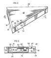
- Figure 2 shows the cassette with a bag contained therein folded into a closed position ready for shipment and storage.
- the combined widths of the spacing panels 50 and 56 (and thus of panels 52 and 54 which are the same width as panels 50 and 56 respectively) which is equal to the spacing between the fold lines 14 and 16, i.e. the width of the panel 18, so that the sides 20 and 22 when the cassette is closed are substantially parallel and substantially perpendicular to the panel 18 to permit easy stacking and storage.
- a bag 70 forming part of the cassette to be filled is incorporated within the cassette structure formed of corrugated board.
- the bag 70 covers substantially the full area of the bottom panel 12 and is folded into U shape configuration following the diagonal panel 18 and the two side panels 20 and 22.
- Emptying spout 72 has an annular encircling flange 74 spaced from the body of the bag 70 by a distance substantially equal to the thickness of the flange 64.
- the bag 70 is fixed to the flap 64 via spout 72 by passing the spout 72 and flange 74 through the large end of aperture 66 and then moving the spout 72 into the narrow end of aperture 66 so that the flap 64 is received between the bag 70 and flange 74 to lock the spout 72, thus the bag 70, to the flap 64 and thus to blank 10.
- This is done with the blank as shown in Figure 1 and the cassette positioned above the bottom panel 12 with the spout 72 projecting upwardly therefrom adjacent the fold line 40.
- the flap 32 is then folded along the fold line 40 and then along the fold line 48 to move the panel 56 into a position perpendicular to the side panel 22 and the reinforcing panel 64 into a position parallel to the side panel 22.
- Flaps 26, 28 and 30 may then be folded similarly to the flap 32 to position their respective spacing panels 50, 52 and 54 perpendicular to the bottom panel 12 and their respective reinforcing flaps 58, 60 and 62 substantially parallel to the bottom panel 12.
- flaps 50 and 58 are parallel to the side panel 20 and the flaps 62 and 64 are parallel to the side panel 22.
- the main bottom panel 12 is then folded along the lines 14 and 16 to place the central diagonal panel 18 in a position substantially perpendicular to the side panels 20 and 22. This moves the reinforcing panel 58 into face to face relationship with the panel 64 and the spout 72 projects through the aperture 68 to be contained within the cassette and tend to hold the cassette in closed position. Similarly the reinforcing flaps 60 and 62 are positioned in face to face relationship by the folding on lines 14 and 16 (see Figure 3).
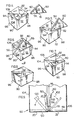
- the folded cassette which has been generally indicated at 80 in Figures 4 to 7 inclusive is used with a box such as the box 90.
- the box 90 incorporates an automatic closing feature the subject matter of applicant's corresponding United States application Serial No. 122,930 filed November 19, 1987 inventors Lau and Gillard (Case 230) which is schematically indicated by the triangular closure panels 92 and 94 that move into close position on squaring of the box.
- Lau and Gillard Cocoase 230
- the cassette may also be used with other boxes.
- the cassette 80 is moved into the box as shown in Figure 5 with the axial end 82 of diagonal panel 18 moving downward and into the bottom corner of the box 90 corresponding with one of the end edges of the triangular top closure panels 92 and 94, i.e. as indicated at 96.
- the trailing end 84 of the cassette 80 i.e. the end of the cassette which will always remain closest to the operator assuming the operator is handling the cassette in a normal manner is then moved downward as indicated by the arrow 86 to move the end 84 into the corner 98 diagonally opposite the corner 96.
- This movement tends to square the box as the size of the cassette is correlated with the size of the box 90 so that when the cassette 80 is forced into the bottom of the container 90 as indicated by the arrow 88 in Figure 7 and as shown when the movement is completed in Figure 9 the corner 98 of the box 90 can be forced toward the end 84 to tend to square the box.
- the cassette 80 is first moved to the sold line position, i.e.
- the cassette side walls 20 and 22 are then moved as indicated by the arrows 100 and 102 respectively from the solid line position into the bottom dash line position which at the same time moves the side walls 104 and 106 (shown in Figure 9) of the carton 90 from their dotted line position to their solid line position as indicated by the arrows 108 and 110 to complete the squaring up operation.
- the two remaining side walls 112 and 114 of the carton 90 obviously are similarly moved into squared position to completely square the box or carton 90.
- the filler tube for filling the bag 70 has been omitted however it is illustrated at 116 in phantom lines in Figure 9 and is included in Figures 10 and 11.
- This filler tube 116 will be connected to a filler spout 118 (see Figures 3, 9, and 11) communicating with the interior of the bag 70.
- the filler spout 118 is normally attached to the tube 116 before the cassette 80 is inserted into the box since it is easier to connect in this position and does not require reaching deep into the box to make the connection.
- the cassette when preconnected with the filler spout 118, may be slightly open when inserted into the box 90.
- the filler spout 72 is withdrawn from the hole 68 before the cassette 80 is introduced into the carton 90, i.e. just before the filler tube 116 is connected to the filler spout 118 on the bag 70.
- the cross section of the carton 90 and thus of the main panel bottom panel 12 is substantially square, thus when the cassette is in its folded condition illustrated in Figure 2, all corners of the two side panels are in substantial alignment, i.e. when the side panels 20 and 22 are folded perpendicular to the diagonal wall 18, the corners of these side walls 20 and 22 remote from fold lines 14 and 16 are in alignment and are located mid-length of the panel 18.
- the size and shape of the main bottom panel 12 will substantially correspond with the cross of the carton with which the cassette is to be used. If the shape of the container or carton 90 is other than square, for example if the cross section of the carton were rectangular, then the two points of the side panels 20 and 21 would be spaced equally on opposite sides of the centre of the panel 18.
- the present invention may also be applied to cassettes adapted to fit cartons with other cross sectional shapes.
- regular shaped polygons i.e. polygons having equal length sides
- the corners between the sides of the polygon on opposite sides of a diagonal panel equivalent to the panel 18 will be symmetrically positioned relative to the centre of the diagonal panel and will completely enclose the bag when in folded condition equivalent to that shown in Figure 2.
Abstract
Description
- The present invention relates to a bag cassette, more particularly the present invention relates to a bag cassette for use in a carton to position the bag and at the same time square the carton when the cassette is properly inserted and positioned within the carton.
- A variety of bag cassettes have been proposed and are being used for inserting bags into boxes so that the bags are oriented in the box and in some cases a spout position relative to the side wall of the box in alignment with an access opening. Generally such bag cassettes include a main bottom wall which may be divided by fold lines into a central rectangular panel and a pair of rectangular side panels. Each side panel has connected to its edge remote from its connection to the central panel a spacing panel which in turn is provided with a reinforcing flap connected thereto by a fold line substantially parallel to the fold line connecting the spacing panel to the rectangular side panel. In other words, the blank forming the cassette is composed of a substantially rectangular panel divided by a plurality of parallel fold lines into a first reinforcing flap, a first spacing panel, a first side panel, a central panel, a second side panel, a second spacing panel and a second reinforcing panel. The central panel has a width between its two fold line connections with the side panels equal to the combined widths of the two spacing panels and normally to provide best protection for the bag which will be enveloped by the cassette blank when folded, the two side panels will be substantially the same size.
- Such a cassette with the bag positioned against the main bottom panel (two side panels and central panel) and contained within the reinforcing flaps is normally inserted into the box with the central panel extending perpendicular to a pair of side walls and substantially centered on these side walls and then the two side panels are folded from a position perpendicular to the central panel to a position parallel thereto to fill out the bottom of the box.
- Preferably the spout of the bag contained within the cassette will extend through one of the reinforcing flaps and be connected thereto so that on filling of the bag the reinforcing flap is folded into face to face relationship with the inside of its corresponding wall in the carton and will bring the spout into alignment with a suitable access opening in the wall of the carton thereby to automatically position the spout.
- It will be apparent that with this type of cassette the box must be substantially squared before the cassette can be introduced and only two walls of the box have a cooperating reinforcing flap (and spacing wall) to reinforce the wall. Multi-walled containers, particularly large bulk containers that are relatively deep (say a container of about 1 cubic meter) it may well be difficult to properly position the cassette to insure that it extends from end to end of the carton and that the fold lines connecting the spacing panels to the side panels align with the desired opposed pair of inside walls of the box to ensure that the cassette is properly positioned to obtain maximum benefit and that on filling the bag, if a spout is held by reinforcing flap, that the spout automatically aligns with the aperture provided in the wall of the box.
- It is an object of the present invention to provide a bag cassette particularly suited for squaring multi-walled containers.
- Broadly, the present invention comprises a cassette or a blank for forming a cassette comprising a main body panel having a pair of spaced parallel diagonal fold lines extending substantially diagonally across said main bottom panel and dividing said main bottom panel into a diagonal panel and a pair of side panels, at least one main flap connected to each of said side panels by a first fold line, a second fold line on each of said main flaps, said second fold line being parallel to said first fold line and dividing its respective said main flap into a spacing panel and a reinforcing flap, the spacing between said diagonal fold lines being substantially equal to the sum of spaces between said first and said second fold lines on a pair of flaps connected one to each of said side panels.
- Preferably a selected one of said reinforcing flaps will be provided with means for securing a spout of a bag to be contained in position in said cassette.
- Preferably the cassette will further comprise a collapsed bag having a main body portion substantially coextensive with said main bottom panel, said spacing panels being folded around said bag in a position substantially perpendicular to its respective said side panel on its respective said first fold line, each said reinforcing flap being folded substantially perpendicular to its respective spacing panel on its respective of said second fold lines and said side panels are folded on said pair of parallel diagonal fold lines each into a position substantially perpendicular to said diagonal panel.
- The present invention also relates to a method of setting up a carton having at least four side walls into a squared position comprising inserting a cassette into said carton said cassette having formed by a main bottom panel divided into a pair of side panels one on each side of a diagonal panel by a pair of fold lines extending substantially diagonally of said main bottom panel, said bottom panel having essentially the same dimensions as the inside of said carton when said carton is in squared position, said cassette being inserted into said carton with said diagonal panel extending substantially diagonally of said carton by moving the first end of said diagonal panel into a bottom corner of said box with said diagonal panel extending upwardly and diagonally of said carton, forcing the end of said diagonal panel remote from said first end downwardly in said carton into position adjacent the bottom corner diagonally opposite said first bottom corner, folding said side panels into a position substantially parallel with said diagonal panel to move the outer edges of said side panels into position adjacent their corresponding inner side walls of said carton thereby to ensure said carton is in squared condition and said cassette properly positioned in said carton.
- Preferably the bag of the cassette is connected to a filling spout and as the bag is filled it forces reinforcing flaps connected to said side panels into face to face relationship with their respective inner side walls of the carton.
- Preferably one of said reinforcing flaps has connected thereto a spout that projects through the reinforcing flap and wherein filling of said bag forces said spout into a corresponding opening in a side wall of said carton against which said selected reinforcing flap is moved by filling of said bag.
- Further features, objects and advantages will be evident from the following detailed description of the preferred embodiments of the present invention taken in conjunction with the accompanying drawings in which:
- Figure 1 is a plan view of a blank for forming a cassette in accordance with one embodiment of the present invention.
- Figure 2 is an isometric view of a cassette constructed in accordance with the present invention.
- Figure 3 is a section along the lines 3-3 of Figure 2.
- Figures 4, 5, 6, 7 and 8 illustrate the sequence of insertion and unfolding of the cassette in a carton to square the carton and position the cassette relative to the carton.
- Figure 9 is a section along the line 9-9 of Figure 7 schematically illustrating the unfolding of the cassette and squaring of the carton.
- Figure 10 is a plan view of an open carton with a cassette in place and in position to be filled.
- Figure 11 is a schematic section along the lines 11-11 of Figure 10 showing the partially filled bag inflated against the reinforcing flaps and forcing the spout into the access opening in the carton wall.
- The present invention will be described in relation to a rectangular container and therefore in relation to a rectangular blank, however it will be understood that other shapes may be used with correspondingly shaped cartons and the shape of the blank adjusted accordingly provided a diagonal can be established between corners of the corner.
- The blank 10 shown in Figure 1, preferably will be made of corrugated board, i.e. a pair of kraft paper lines spaced by a corrugated medium, cut and scored to form the blank as illustrated at 10. This blank 10 is for a carton of square cross sections and has a main bottom panel or
wall 12 which is divided by a pair of diagonal substantiallyparallel fold lines diagonal panel 18 and a pair ofside panels panels - In the illustrated arrangement the axial ends of the
central panel 18 are pointed as indicated at 24 so that these corners may extend right into the corner of the carton as will be described hereinbelow but this is not essential and may be deleted. Each of thetriangular side panels main flaps fold lines fold lines bottom panel 12 and two sides of each of the side panels. - Each of these
main flaps fold line spacing panel flap panels panels fold lines spacing panels emptying spout 72 on a bag 70 (see Figure 3) as will be described in more detail hereinbelow. - In the illustrated arrangement the
panel 64 is provided with a key hole shapedopening 66 adapted to lock aflanged spout 72 to theflap 64 is shown. The narrow end of theslot 66 aligns with ahole 68 in theflap 58 when the cassette is in closed position as will be described hereinbelow. - Figure 2 shows the cassette with a bag contained therein folded into a closed position ready for shipment and storage. It will be noted that the combined widths of the
spacing panels 50 and 56 (and thus ofpanels panels fold lines panel 18, so that thesides panel 18 to permit easy stacking and storage. - In the arrangement shown in Figure 2 the triangular sections have been eliminated from the ends of the
panel 18. - It will be clearer from Figure 3 how a
bag 70 forming part of the cassette to be filled is incorporated within the cassette structure formed of corrugated board. Thebag 70 covers substantially the full area of thebottom panel 12 and is folded into U shape configuration following thediagonal panel 18 and the twoside panels Emptying spout 72 has an annular encircling flange 74 spaced from the body of thebag 70 by a distance substantially equal to the thickness of theflange 64. Thebag 70 is fixed to theflap 64 viaspout 72 by passing thespout 72 and flange 74 through the large end ofaperture 66 and then moving thespout 72 into the narrow end ofaperture 66 so that theflap 64 is received between thebag 70 and flange 74 to lock thespout 72, thus thebag 70, to theflap 64 and thus to blank 10. This is done with the blank as shown in Figure 1 and the cassette positioned above thebottom panel 12 with thespout 72 projecting upwardly therefrom adjacent thefold line 40. Theflap 32 is then folded along thefold line 40 and then along thefold line 48 to move thepanel 56 into a position perpendicular to theside panel 22 and the reinforcingpanel 64 into a position parallel to theside panel 22. - The flange 74 passes through the large end of the
aperture 66 then the bag and blank 10 are moved relatively to slide thespout 72 into the narrow portion of theopening 66 and position the bag in proper position over thebottom panel 12.Flaps flap 32 to position theirrespective spacing panels bottom panel 12 and their respective reinforcingflaps bottom panel 12. Inparticular flaps side panel 20 and theflaps side panel 22. - The
main bottom panel 12 is then folded along thelines diagonal panel 18 in a position substantially perpendicular to theside panels panel 58 into face to face relationship with thepanel 64 and thespout 72 projects through theaperture 68 to be contained within the cassette and tend to hold the cassette in closed position. Similarly the reinforcingflaps lines 14 and 16 (see Figure 3). - The folded cassette which has been generally indicated at 80 in Figures 4 to 7 inclusive is used with a box such as the
box 90. Thebox 90 incorporates an automatic closing feature the subject matter of applicant's corresponding United States application Serial No. 122,930 filed November 19, 1987 inventors Lau and Gillard (Case 230) which is schematically indicated by thetriangular closure panels - As illustrated, before the box is completely squared, the
cassette 80 is moved into the box as shown in Figure 5 with theaxial end 82 ofdiagonal panel 18 moving downward and into the bottom corner of thebox 90 corresponding with one of the end edges of the triangulartop closure panels - The
trailing end 84 of thecassette 80, i.e. the end of the cassette which will always remain closest to the operator assuming the operator is handling the cassette in a normal manner is then moved downward as indicated by thearrow 86 to move theend 84 into thecorner 98 diagonally opposite thecorner 96. This movement tends to square the box as the size of the cassette is correlated with the size of thebox 90 so that when thecassette 80 is forced into the bottom of thecontainer 90 as indicated by thearrow 88 in Figure 7 and as shown when the movement is completed in Figure 9 thecorner 98 of thebox 90 can be forced toward theend 84 to tend to square the box. Referring to Figure 9 it will be noted that thecassette 80 is first moved to the sold line position, i.e. extending diagonally across thebox 90 from thecorner 96 toward thecorner 98, thecassette side walls arrows side walls 104 and 106 (shown in Figure 9) of thecarton 90 from their dotted line position to their solid line position as indicated by the arrows 108 and 110 to complete the squaring up operation. The tworemaining side walls carton 90 obviously are similarly moved into squared position to completely square the box orcarton 90. - In Figures 4 to 8 inclusive the filler tube for filling the
bag 70 has been omitted however it is illustrated at 116 in phantom lines in Figure 9 and is included in Figures 10 and 11. Thisfiller tube 116 will be connected to a filler spout 118 (see Figures 3, 9, and 11) communicating with the interior of thebag 70. Thefiller spout 118 is normally attached to thetube 116 before thecassette 80 is inserted into the box since it is easier to connect in this position and does not require reaching deep into the box to make the connection. The cassette, when preconnected with thefiller spout 118, may be slightly open when inserted into thebox 90. - As shown in Figures 10 and 11, after the cassette has been positioned material is fed through the
filler tube 116 which starts to fill thebag 70. As thebag 70 fills it unfolds the reinforcingflaps adjacent side wall carton 90. - It will be apparent that the
spacing panels carton 90 when the cassette is unfolded to the final horizontal position shown in Figure 9 and that the reinforcing flaps are then folded from a position perpendicular to these panels into a position in the same place as these panels against their respective carton walls. It has been found that providing a main flap in face to face relationship with each carton wall provides significant reinforcement to the container. - The
filler spout 72 is withdrawn from thehole 68 before thecassette 80 is introduced into thecarton 90, i.e. just before thefiller tube 116 is connected to thefiller spout 118 on thebag 70. - Folding of the
flap 64 in a position against itsrespective wall 104 as thebag 70 is filled moves the emptyingspout 72, which is accurately located by the positioning of thecassette 80 in the bottom of thecontainer 90, into the aperture 120 (see Figures 10 and 11) so that thespout 72 is easily accessible when the carton is filled. - In the illustrated embodiment, the cross section of the
carton 90 and thus of the mainpanel bottom panel 12 is substantially square, thus when the cassette is in its folded condition illustrated in Figure 2, all corners of the two side panels are in substantial alignment, i.e. when theside panels diagonal wall 18, the corners of theseside walls fold lines panel 18. - In all cases the size and shape of the main
bottom panel 12 will substantially correspond with the cross of the carton with which the cassette is to be used. If the shape of the container orcarton 90 is other than square, for example if the cross section of the carton were rectangular, then the two points of theside panels 20 and 21 would be spaced equally on opposite sides of the centre of thepanel 18. - The present invention may also be applied to cassettes adapted to fit cartons with other cross sectional shapes. Generally with regular shaped polygons, (i.e. polygons having equal length sides) having an equal number of sides, the corners between the sides of the polygon on opposite sides of a diagonal panel equivalent to the
panel 18 will be symmetrically positioned relative to the centre of the diagonal panel and will completely enclose the bag when in folded condition equivalent to that shown in Figure 2. - For cartons having cross sectional shapes other than those with equal sides, it may be necessary to adjust the size of the reinforcing flaps equivalent to, for example the
flaps - Having described the invention, modifications will be evident to those skilled in the art without department from the spirit of the invention as defined in the appended claims.
Claims (10)
Priority Applications (1)
| Application Number | Priority Date | Filing Date | Title |
|---|---|---|---|
| AT89303487T ATE93196T1 (en) | 1988-05-06 | 1989-04-10 | BAG CASSETTE FOR BULK CONTAINERS. |
Applications Claiming Priority (2)
| Application Number | Priority Date | Filing Date | Title |
|---|---|---|---|
| US07/190,824 US4863021A (en) | 1988-05-06 | 1988-05-06 | Bulk bin bag cassette |
| US190824 | 1994-02-02 |
Publications (2)
| Publication Number | Publication Date |
|---|---|
| EP0340922A1 true EP0340922A1 (en) | 1989-11-08 |
| EP0340922B1 EP0340922B1 (en) | 1993-08-18 |
Family
ID=22702951
Family Applications (1)
| Application Number | Title | Priority Date | Filing Date |
|---|---|---|---|
| EP89303487A Expired - Lifetime EP0340922B1 (en) | 1988-05-06 | 1989-04-10 | Bulk bin bag cassette |
Country Status (5)
| Country | Link |
|---|---|
| US (1) | US4863021A (en) |
| EP (1) | EP0340922B1 (en) |
| AT (1) | ATE93196T1 (en) |
| DE (1) | DE68908461T2 (en) |
| ES (1) | ES2045418T3 (en) |
Cited By (1)
| Publication number | Priority date | Publication date | Assignee | Title |
|---|---|---|---|---|
| US10020759B2 (en) | 2015-08-04 | 2018-07-10 | The Boeing Company | Parallel modular converter architecture for efficient ground electric vehicles |
Families Citing this family (7)
| Publication number | Priority date | Publication date | Assignee | Title |
|---|---|---|---|---|
| US5213255A (en) * | 1991-05-01 | 1993-05-25 | Waldorf Corporation | Opening structure for wedge-shaped pie carton |
| US5558224A (en) * | 1995-05-08 | 1996-09-24 | Riverwood International Corporation | Triangular article carrier |
| USD418412S (en) * | 1998-04-13 | 2000-01-04 | Seishi Komatsu | Package |
| US20060169757A1 (en) * | 2005-02-01 | 2006-08-03 | Mcdowell Richard B | Multi-ply collapsible bulk container |
| US7552838B2 (en) * | 2005-02-01 | 2009-06-30 | Menasha Corporation | Cartridge and method for filling a bulk container with a flowable substance |
| EP2108598A1 (en) | 2008-04-08 | 2009-10-14 | DLC Developments Limited | Bag-in-box packaging system for bulk flowable materials |
| US8950654B2 (en) | 2012-06-08 | 2015-02-10 | Menasha Corporation | Folding carton with auto-erecting bottom |
Citations (6)
| Publication number | Priority date | Publication date | Assignee | Title |
|---|---|---|---|---|
| US2342324A (en) * | 1942-06-24 | 1944-02-22 | Brooks Paper Company | Bag-expanding means |
| US2981443A (en) * | 1956-09-04 | 1961-04-25 | Line Dispensers Inc B | Container and spout therefor |
| US3143249A (en) * | 1962-01-08 | 1964-08-04 | Stone Container Corp | Collapsible bulk fluid container |
| US3206094A (en) * | 1962-11-21 | 1965-09-14 | Reed Paper Group Ltd | Lined container |
| US3399818A (en) * | 1966-05-17 | 1968-09-03 | Douglass M. Stegner | Container |
| AU493047B2 (en) * | 1973-09-11 | 1978-05-11 | Pak Pacific Corporation Pty Ltd | improvements in containers |
Family Cites Families (4)
| Publication number | Priority date | Publication date | Assignee | Title |
|---|---|---|---|---|
| US1814561A (en) * | 1928-08-25 | 1931-07-14 | William L Krumm | Box |
| US4313542A (en) * | 1979-07-13 | 1982-02-02 | Champion International Corporation | Single-serving pie carton and blank |
| US4492333A (en) * | 1982-08-25 | 1985-01-08 | Champion International Corporation | Single slice pie carton with slanted openable rear wall and blank for forming same |
| GB2194512B (en) * | 1986-08-30 | 1989-12-20 | Tpt Ltd | Device facilitating filling and unfolding of bag within outer casing |
-
1988
- 1988-05-06 US US07/190,824 patent/US4863021A/en not_active Expired - Lifetime
-
1989
- 1989-04-10 EP EP89303487A patent/EP0340922B1/en not_active Expired - Lifetime
- 1989-04-10 DE DE89303487T patent/DE68908461T2/en not_active Expired - Lifetime
- 1989-04-10 AT AT89303487T patent/ATE93196T1/en not_active IP Right Cessation
- 1989-04-10 ES ES89303487T patent/ES2045418T3/en not_active Expired - Lifetime
Patent Citations (6)
| Publication number | Priority date | Publication date | Assignee | Title |
|---|---|---|---|---|
| US2342324A (en) * | 1942-06-24 | 1944-02-22 | Brooks Paper Company | Bag-expanding means |
| US2981443A (en) * | 1956-09-04 | 1961-04-25 | Line Dispensers Inc B | Container and spout therefor |
| US3143249A (en) * | 1962-01-08 | 1964-08-04 | Stone Container Corp | Collapsible bulk fluid container |
| US3206094A (en) * | 1962-11-21 | 1965-09-14 | Reed Paper Group Ltd | Lined container |
| US3399818A (en) * | 1966-05-17 | 1968-09-03 | Douglass M. Stegner | Container |
| AU493047B2 (en) * | 1973-09-11 | 1978-05-11 | Pak Pacific Corporation Pty Ltd | improvements in containers |
Cited By (1)
| Publication number | Priority date | Publication date | Assignee | Title |
|---|---|---|---|---|
| US10020759B2 (en) | 2015-08-04 | 2018-07-10 | The Boeing Company | Parallel modular converter architecture for efficient ground electric vehicles |
Also Published As
| Publication number | Publication date |
|---|---|
| ATE93196T1 (en) | 1993-09-15 |
| US4863021A (en) | 1989-09-05 |
| DE68908461T2 (en) | 1994-01-05 |
| EP0340922B1 (en) | 1993-08-18 |
| DE68908461D1 (en) | 1993-09-23 |
| ES2045418T3 (en) | 1994-01-16 |
Similar Documents
| Publication | Publication Date | Title |
|---|---|---|
| US3756471A (en) | Dispenser container having a tear-out sight gauge | |
| US4341338A (en) | Corrugated box bulk materials | |
| US3194471A (en) | Bulk container device | |
| US6085969A (en) | Paperboard carton and blank therefor | |
| US3910487A (en) | Reclosable carton | |
| US2493337A (en) | Lined carton or container | |
| US3397831A (en) | Reinforced bulk pack container | |
| US6168074B1 (en) | End opening bulk material box | |
| US4394905A (en) | Auto platform carton | |
| US5102382A (en) | Method and apparatus for closing bottom end flaps of a carton | |
| US4635815A (en) | Reinforced bulk material container | |
| US4154387A (en) | Two-cell bulk container with partial bellows bottom | |
| US5419485A (en) | End opening reinforced bulk material box | |
| US4830271A (en) | End closure for a multi-walled container | |
| EP0340922B1 (en) | Bulk bin bag cassette | |
| US4469224A (en) | Carton blank and carton for a bicycle | |
| US5066269A (en) | Method and apparatus for closing bottom end flaps of a carton | |
| US4174803A (en) | Multicell corrugated bulk container | |
| US4945711A (en) | Bulk bin bag cassette | |
| US4899927A (en) | Collapsible container | |
| US5639015A (en) | End opening bulk material box | |
| US7837089B2 (en) | Bulk material box | |
| US5447269A (en) | Multiple unit box and blank therefor | |
| US3041942A (en) | Method of assembling multi-wall bulk pak shipping containers | |
| CA1298218C (en) | Bulk bin bag cassette |
Legal Events
| Date | Code | Title | Description |
|---|---|---|---|
| PUAI | Public reference made under article 153(3) epc to a published international application that has entered the european phase |
Free format text: ORIGINAL CODE: 0009012 |
|
| AK | Designated contracting states |
Kind code of ref document: A1 Designated state(s): AT BE CH DE ES FR GB IT LI LU NL SE |
|
| 17P | Request for examination filed |
Effective date: 19900504 |
|
| 17Q | First examination report despatched |
Effective date: 19910823 |
|
| GRAA | (expected) grant |
Free format text: ORIGINAL CODE: 0009210 |
|
| AK | Designated contracting states |
Kind code of ref document: B1 Designated state(s): AT BE CH DE ES FR GB IT LI LU NL SE |
|
| REF | Corresponds to: |
Ref document number: 93196 Country of ref document: AT Date of ref document: 19930915 Kind code of ref document: T |
|
| ITF | It: translation for a ep patent filed |
Owner name: BUGNION S.P.A. |
|
| REF | Corresponds to: |
Ref document number: 68908461 Country of ref document: DE Date of ref document: 19930923 |
|
| ET | Fr: translation filed | ||
| REG | Reference to a national code |
Ref country code: ES Ref legal event code: FG2A Ref document number: 2045418 Country of ref document: ES Kind code of ref document: T3 |
|
| PLBE | No opposition filed within time limit |
Free format text: ORIGINAL CODE: 0009261 |
|
| STAA | Information on the status of an ep patent application or granted ep patent |
Free format text: STATUS: NO OPPOSITION FILED WITHIN TIME LIMIT |
|
| EPTA | Lu: last paid annual fee | ||
| 26N | No opposition filed | ||
| EAL | Se: european patent in force in sweden |
Ref document number: 89303487.6 |
|
| REG | Reference to a national code |
Ref country code: GB Ref legal event code: IF02 |
|
| PGFP | Annual fee paid to national office [announced via postgrant information from national office to epo] |
Ref country code: AT Payment date: 20030306 Year of fee payment: 15 |
|
| PGFP | Annual fee paid to national office [announced via postgrant information from national office to epo] |
Ref country code: CH Payment date: 20030317 Year of fee payment: 15 |
|
| PGFP | Annual fee paid to national office [announced via postgrant information from national office to epo] |
Ref country code: NL Payment date: 20030325 Year of fee payment: 15 |
|
| PGFP | Annual fee paid to national office [announced via postgrant information from national office to epo] |
Ref country code: BE Payment date: 20030402 Year of fee payment: 15 |
|
| PGFP | Annual fee paid to national office [announced via postgrant information from national office to epo] |
Ref country code: LU Payment date: 20030605 Year of fee payment: 15 |
|
| PG25 | Lapsed in a contracting state [announced via postgrant information from national office to epo] |
Ref country code: LU Free format text: LAPSE BECAUSE OF NON-PAYMENT OF DUE FEES Effective date: 20040410 Ref country code: AT Free format text: LAPSE BECAUSE OF NON-PAYMENT OF DUE FEES Effective date: 20040410 |
|
| PG25 | Lapsed in a contracting state [announced via postgrant information from national office to epo] |
Ref country code: LI Free format text: LAPSE BECAUSE OF NON-PAYMENT OF DUE FEES Effective date: 20040430 Ref country code: BE Free format text: LAPSE BECAUSE OF NON-PAYMENT OF DUE FEES Effective date: 20040430 Ref country code: CH Free format text: LAPSE BECAUSE OF NON-PAYMENT OF DUE FEES Effective date: 20040430 |
|
| BERE | Be: lapsed |
Owner name: *MACMILLAN BLOEDEL LTD Effective date: 20040430 |
|
| PG25 | Lapsed in a contracting state [announced via postgrant information from national office to epo] |
Ref country code: NL Free format text: LAPSE BECAUSE OF NON-PAYMENT OF DUE FEES Effective date: 20041101 |
|
| REG | Reference to a national code |
Ref country code: CH Ref legal event code: PL |
|
| NLV4 | Nl: lapsed or anulled due to non-payment of the annual fee |
Effective date: 20041101 |
|
| PGFP | Annual fee paid to national office [announced via postgrant information from national office to epo] |
Ref country code: GB Payment date: 20080317 Year of fee payment: 20 |
|
| PGFP | Annual fee paid to national office [announced via postgrant information from national office to epo] |
Ref country code: ES Payment date: 20080409 Year of fee payment: 20 Ref country code: DE Payment date: 20080430 Year of fee payment: 20 |
|
| PGFP | Annual fee paid to national office [announced via postgrant information from national office to epo] |
Ref country code: IT Payment date: 20080419 Year of fee payment: 20 |
|
| PGFP | Annual fee paid to national office [announced via postgrant information from national office to epo] |
Ref country code: SE Payment date: 20080404 Year of fee payment: 20 |
|
| PGFP | Annual fee paid to national office [announced via postgrant information from national office to epo] |
Ref country code: FR Payment date: 20080403 Year of fee payment: 20 |
|
| REG | Reference to a national code |
Ref country code: GB Ref legal event code: PE20 Expiry date: 20090409 |
|
| EUG | Se: european patent has lapsed | ||
| REG | Reference to a national code |
Ref country code: ES Ref legal event code: FD2A Effective date: 20090411 |
|
| PG25 | Lapsed in a contracting state [announced via postgrant information from national office to epo] |
Ref country code: ES Free format text: LAPSE BECAUSE OF EXPIRATION OF PROTECTION Effective date: 20090411 |
|
| PG25 | Lapsed in a contracting state [announced via postgrant information from national office to epo] |
Ref country code: GB Free format text: LAPSE BECAUSE OF EXPIRATION OF PROTECTION Effective date: 20090409 |