EP0341741B1 - Method of winding film on a spool and loading the spool with the film into a magazine and a system for carrying out the method - Google Patents
Method of winding film on a spool and loading the spool with the film into a magazine and a system for carrying out the method Download PDFInfo
- Publication number
- EP0341741B1 EP0341741B1 EP89108616A EP89108616A EP0341741B1 EP 0341741 B1 EP0341741 B1 EP 0341741B1 EP 89108616 A EP89108616 A EP 89108616A EP 89108616 A EP89108616 A EP 89108616A EP 0341741 B1 EP0341741 B1 EP 0341741B1
- Authority
- EP
- European Patent Office
- Prior art keywords
- spool
- film
- pallet
- film winding
- roll
- Prior art date
- Legal status (The legal status is an assumption and is not a legal conclusion. Google has not performed a legal analysis and makes no representation as to the accuracy of the status listed.)
- Expired - Lifetime
Links
Images


Classifications
-
- G—PHYSICS
- G03—PHOTOGRAPHY; CINEMATOGRAPHY; ANALOGOUS TECHNIQUES USING WAVES OTHER THAN OPTICAL WAVES; ELECTROGRAPHY; HOLOGRAPHY
- G03B—APPARATUS OR ARRANGEMENTS FOR TAKING PHOTOGRAPHS OR FOR PROJECTING OR VIEWING THEM; APPARATUS OR ARRANGEMENTS EMPLOYING ANALOGOUS TECHNIQUES USING WAVES OTHER THAN OPTICAL WAVES; ACCESSORIES THEREFOR
- G03B17/00—Details of cameras or camera bodies; Accessories therefor
- G03B17/26—Holders for containing light sensitive material and adapted to be inserted within the camera
-
- Y—GENERAL TAGGING OF NEW TECHNOLOGICAL DEVELOPMENTS; GENERAL TAGGING OF CROSS-SECTIONAL TECHNOLOGIES SPANNING OVER SEVERAL SECTIONS OF THE IPC; TECHNICAL SUBJECTS COVERED BY FORMER USPC CROSS-REFERENCE ART COLLECTIONS [XRACs] AND DIGESTS
- Y10—TECHNICAL SUBJECTS COVERED BY FORMER USPC
- Y10T—TECHNICAL SUBJECTS COVERED BY FORMER US CLASSIFICATION
- Y10T29/00—Metal working
- Y10T29/49—Method of mechanical manufacture
- Y10T29/49826—Assembling or joining
- Y10T29/49828—Progressively advancing of work assembly station or assembled portion of work
- Y10T29/49829—Advancing work to successive stations [i.e., assembly line]
-
- Y—GENERAL TAGGING OF NEW TECHNOLOGICAL DEVELOPMENTS; GENERAL TAGGING OF CROSS-SECTIONAL TECHNOLOGIES SPANNING OVER SEVERAL SECTIONS OF THE IPC; TECHNICAL SUBJECTS COVERED BY FORMER USPC CROSS-REFERENCE ART COLLECTIONS [XRACs] AND DIGESTS
- Y10—TECHNICAL SUBJECTS COVERED BY FORMER USPC
- Y10T—TECHNICAL SUBJECTS COVERED BY FORMER US CLASSIFICATION
- Y10T29/00—Metal working
- Y10T29/49—Method of mechanical manufacture
- Y10T29/49826—Assembling or joining
- Y10T29/49863—Assembling or joining with prestressing of part
- Y10T29/4987—Elastic joining of parts
-
- Y—GENERAL TAGGING OF NEW TECHNOLOGICAL DEVELOPMENTS; GENERAL TAGGING OF CROSS-SECTIONAL TECHNOLOGIES SPANNING OVER SEVERAL SECTIONS OF THE IPC; TECHNICAL SUBJECTS COVERED BY FORMER USPC CROSS-REFERENCE ART COLLECTIONS [XRACs] AND DIGESTS
- Y10—TECHNICAL SUBJECTS COVERED BY FORMER USPC
- Y10T—TECHNICAL SUBJECTS COVERED BY FORMER US CLASSIFICATION
- Y10T29/00—Metal working
- Y10T29/49—Method of mechanical manufacture
- Y10T29/49826—Assembling or joining
- Y10T29/49863—Assembling or joining with prestressing of part
- Y10T29/49874—Prestressing rod, filament or strand
-
- Y—GENERAL TAGGING OF NEW TECHNOLOGICAL DEVELOPMENTS; GENERAL TAGGING OF CROSS-SECTIONAL TECHNOLOGIES SPANNING OVER SEVERAL SECTIONS OF THE IPC; TECHNICAL SUBJECTS COVERED BY FORMER USPC CROSS-REFERENCE ART COLLECTIONS [XRACs] AND DIGESTS
- Y10—TECHNICAL SUBJECTS COVERED BY FORMER USPC
- Y10T—TECHNICAL SUBJECTS COVERED BY FORMER US CLASSIFICATION
- Y10T29/00—Metal working
- Y10T29/53—Means to assemble or disassemble
- Y10T29/53313—Means to interrelatedly feed plural work parts from plural sources without manual intervention
- Y10T29/53365—Multiple station assembly apparatus
-
- Y—GENERAL TAGGING OF NEW TECHNOLOGICAL DEVELOPMENTS; GENERAL TAGGING OF CROSS-SECTIONAL TECHNOLOGIES SPANNING OVER SEVERAL SECTIONS OF THE IPC; TECHNICAL SUBJECTS COVERED BY FORMER USPC CROSS-REFERENCE ART COLLECTIONS [XRACs] AND DIGESTS
- Y10—TECHNICAL SUBJECTS COVERED BY FORMER USPC
- Y10T—TECHNICAL SUBJECTS COVERED BY FORMER US CLASSIFICATION
- Y10T29/00—Metal working
- Y10T29/53—Means to assemble or disassemble
- Y10T29/534—Multiple station assembly or disassembly apparatus
-
- Y—GENERAL TAGGING OF NEW TECHNOLOGICAL DEVELOPMENTS; GENERAL TAGGING OF CROSS-SECTIONAL TECHNOLOGIES SPANNING OVER SEVERAL SECTIONS OF THE IPC; TECHNICAL SUBJECTS COVERED BY FORMER USPC CROSS-REFERENCE ART COLLECTIONS [XRACs] AND DIGESTS
- Y10—TECHNICAL SUBJECTS COVERED BY FORMER USPC
- Y10T—TECHNICAL SUBJECTS COVERED BY FORMER US CLASSIFICATION
- Y10T29/00—Metal working
- Y10T29/53—Means to assemble or disassemble
- Y10T29/53465—Film or tape cartridge
-
- Y—GENERAL TAGGING OF NEW TECHNOLOGICAL DEVELOPMENTS; GENERAL TAGGING OF CROSS-SECTIONAL TECHNOLOGIES SPANNING OVER SEVERAL SECTIONS OF THE IPC; TECHNICAL SUBJECTS COVERED BY FORMER USPC CROSS-REFERENCE ART COLLECTIONS [XRACs] AND DIGESTS
- Y10—TECHNICAL SUBJECTS COVERED BY FORMER USPC
- Y10T—TECHNICAL SUBJECTS COVERED BY FORMER US CLASSIFICATION
- Y10T29/00—Metal working
- Y10T29/53—Means to assemble or disassemble
- Y10T29/53478—Means to assemble or disassemble with magazine supply
Definitions
- This invention relates to a method of winding a photographic roll film such as 16mm film or 35mm film around a spool and loading the roll film-spool assembly into a film magazine, and a system for carrying out the method.
- the spool with the roll film must be delivered from one pickup arm to another pickup arm a plurality of times, and since the spool carrying thereon a roll film is hard to stably hold, trouble is apt to occur during delivery of the spool, which can cause various troubles such as interruption of the assembly line.
- the step of winding the roll film around the spool takes a much longer time than the other steps such as the step of inserting the spool with the roll film into a film magazine, or the step of capping the film magazine. Accordingly, in the known system in which the spool is provided with a roll film and sent to the magazine assembly station one by one, the time required to assemble each film magazine is governed by the time required to wind the roll film around the spool. This is not preferable from the viewpoint of increase in the productivity.
- the primary object of the present invention is to provide a method of winding a photographic roll film around a spool and loading the roll film-spool assembly into a film magazine in which troubles which accompanies delivery of the roll film-spool assembly can be prevented.
- Another object of the present invention is to provide a method of winding a photographic roll film around a spool and loading the roll film-spool assembly into a film magazine in which the effective time required to assemble each film cassette can be shortened.
- Still another object of the present invention is to provide a system for carrying out the method.
- a spool around which a roll film is to be wound is carried by a pallet having a spool holding shaft which holds the spool and rotates the spool under a force transmitted to the spool holding shaft from outside the pallet and a film pinch means which pinches the outer end portion (the leader portion) of the roll film wound around the spool and is moved from station to station in a film cassette assembly line.
- a method of winding a plurality of unexposed photographic roll film around plurality of spools and loading each spool with the wound film into a film magazine as claimed in claim 2 which is similar to the method in accordance with the first aspect of the present invention.
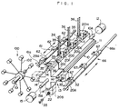
- a first indexing means 10 is rotatable about a shaft 10A, and is provided with four guide rails 11 which are arranged at intervals of 90° about the shaft 10A and extend in parallel to the shaft 10A.
- the shaft 10A is connected to a first indexer driving means 12 and is intermittently rotated in the counterclockwise direction by 90° at intervals of a predetermined time T1.
- a second indexing 13 is provided on the side of the first indexing means 10 opposite to the first indexer driving means 12 and is rotatable about a shaft 13A which is coaxial with the shaft 10A.
- the second indexing means 13 is provided with four guide rails 14 each of which is the same as the guide rail 11 of the first indexing means 10 in cross-sectional shape and adapted to be in alignment with one of the guide rails 11.
- the shaft 13A of the second indexing means 13 is connected to a second indexer driving means 15 and is intermittently rotated in the counterclockwise direction by 90° at intervals of a predetermined time T2 which is one third of the predetermined time T1. That is, the first indexing means 10 is rotated once every time the second indexing means 13 is rotated three times, or the first indexing means 10 is rotated by 90° every time the second indexing means 13 is rotated by 270°.
- a plurality of film winding pallets 20 (20A, 20B, 20C ⁇ ) are slid along the guide rails 11 and 14 in the longitudinal direction thereof in engagement with the guide rails.
- Reference numerals 20A, 20B, 20C and so on will sometimes be used in order to denote the film winding pallets 20 per se which are positioned in particular positions and sometimes be used in order to denote the particular positions, hereinbelow.
- the film winding pallet 20 has a carriage body 20a provided on the lower surface thereof with an engagement groove 21 which is adapted to be engaged with the guide rails 11 and 14 so that the carriage body 20a can slide along the rails.
- a bearing unit (not shown) is provided in the engagement groove 21 in order to facilitate the slide of the carriage body 20a along the rails 11 and 14.
- the film winding pallet 20 is provided with a spool holding shaft 22 which extends in parallel to the the engagement groove 21.
- the spool holding shaft 22 is provided with a collet chuck 22A on the front end thereof.
- the collet chuck 22A is given a work holding force by a coil spring 24, and the transmission of the work holding force to the chuck 22A is interrupted when a spool release lever 25 is depressed.
- the spool holding shaft 22 is connected, by way of a rotation transmission mechanism (not shown), to a rotation inputting shaft 23 which projects from a side of the carriage body 20a.
- the rotation inputting shaft 23 is provided with a claw clutch 23A on the outer end thereof.
- a pair of brake members 27 project outside from the side of the carriage body 20a and are urged outward by springs 26. Each brake member 27 is connected to a brake pad (not shown) and normally presses it against the spool holding shaft 22 so as to restrain the rotation of spool holding shaft 22. When pushed inward by an external force, the brake member 27 removes the brake pad from the spool holding shaft 22 and permits the spool holding shaft 22 to rotate freely.
- a pair of film pinch arms 29A and 29B are mounted on the top of the carriage body 20a so that they can rotate in a horizontal plane respectively about pivot shafts 28A and 28B.
- the film pinch arms 29A and 29B are moved between an open position shown in Figure 2 where they are positioned away from each other and a closure position above and in front of the collet chuck 22A where they abut against each other.
- the arms 29A and 29B forms a toggle mechanism and held in the open position or the closure position under the force of a toggle spring 30.
- the arms 29A and 29B are positioned one of the positions by operation of an arm opening and closing lever 31.
- a hook roller 32 which is used when the film winding pallet 20 is moved is provided in the vicinity of the arm opening and closing lever 31.
- the film winding pallet 20 chucks the longer boss portion 35E of a spool 35 for 35mm film ( Figure 3) with the collet chuck 22A in a manner which will be described later.
- three film winding pallets 20 with the spools 35 chucked are positioned on the uppermost one of the guide rails 11 of the first indexing means 10 as shown in Figure 1.
- the three film winding pallets 20 are spaced from each other by a predetermined distance and arranged in line so that the spool holding shafts 22 of the respective film winding pallets 20 are in alignment with each other in parallel to the rail 11.
- a roll film of a predetermined length is fed to each of the three spools 35 and an end of the roll film is brought into engagement with the spool 35.
- the operation of the engaging the roll film with the spool 35 will be described, hereinbelow, with reference to Figures 4 to 6 which show in detail the mechanism for the purpose.
- the mechanism is omitted in Figure 1.
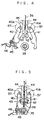
- Three pairs of clampers 40 and 41 are disposed so that one pair of clampers 40 and 41 are disposed on opposite sides of each spool 35 held by the film winding pallet 20 as shown in Figure 4.
- the clampers 40 and 41 are pivoted toward each other and clamp the spool 35 therebetween as shown in Figure 5 when the film winding pallet 20 holding the spool 35 is positioned in a predetermined position.
- the spool 35 is held so that its cassette slit 35A ( Figure 3) opens upward. Then a roll film 36 which has been held above a pair of guide plates 44 with its trailing end portion 36B directed downward is dropped between the guide plates 44 and a pair of feed rollers 42 and 43 below the guide plates 44 are rotated as shown by the arrows in Figure 5, whereby the trailing end portion 36B of the roll film 36 is inserted into the slit 35A of the spool 35.
- the trailing end portion 36B of the roll film 36 has been cut into the shape shown in Figure 7 and is provided with a pair of engagement holes 36A.
- the spool 35 is provided with a pair of engagement claws 35B in the slit 35A.
- Each engagement claw 35B has an inclined surface and hooked tip portion, and the engagement holes 36A are brought into engagement with the engagement claws 35B as the trailing end portion 36B of the roll film 36 is inserted into the slit 35A as shown in Figure 7.
- the trailing end portion 36B is connected to the spool 35.
- the trailing end portion 36B partly projects downward from the lower opening of the slit 35A (e.g., by 1mm).
- the projecting part of the trailing end portion 36B pushes downward a film insertion detecting lever 45 which is shown in Figures 4 and 5.
- the downward movement of the lever 45 is detected by a photoelectric sensor 46.
- FIG 8 shows winding driving means which rotates the spools 35 in order to wind the roll films 36 around the spools 35.
- the winding driving means is omitted in Figure 1.
- a table 50 is moved along a pair of guide rails 51 to the side of the first indexing means 10 as shown in Figure 8.
- Three winding driving shafts 52 are located on the table 50.
- Each driving shaft 52 is connected to the output shaft of a servomotor 54 by way of a clutch-brake unit 53.
- Each driving shaft 52 has a claw clutch (not shown) on the free end face thereof and is opposed to the rotation inputting shaft 23 of one of the film winding pallets 20.
- a pinch arm driving member 60 is moved in the direction parallel to the guide rails 11.
- the pinch arm driving member 60 has three abutment portions (not shown) which are adapted to abut against the arm opening and closing levers 31 of the respective film winding pallets 20, and when the pinch arm diving member 60 is moved in the direction parallel to the guide rails 11, each projection urges the corresponding arm opening and closing lever 31 to bring the film pinch arms 29A and 29B of the corresponding film winding pallet 20 to said closure position.
- the leader portion of the roll film 36 is pinched therebetween.
- each spool 35 is prevented from being reversed under the resiliency of the roll film 36 so as to unroll the roll film 36.
- the first indexer driving means 12 rotates the first indexing means 10 by 90°.
- the second indexing means 13 is also rotated by 90°. Accordingly, the three film winding pallets 20 which have been in the positions indicated at 20F, 20G and 20H in Figure 1 are moved to the positions indicated at 20C, 20D and 20E.
- Another three film winding pallets 20 have been positioned on the guide rail 11 which is in the uppermost position after the first indexing means 10 is thus rotated by 90° in the manner which will become apparent later, and the roll films 36 are wound around the spools 35 held by the another three film winding pallets 20 in the manner described above.
- a shifter 61 extends in parallel to the guide rails 11 and is opposed to the film winding pallets 20C to 20E.
- the shifter 61 comprises a guide rod 61a and three engagement members 62 which are slidable on the guide rod 61a and rotatable about the longitudinal axis of the guide rod 61a together with the guide rod 61a.
- the three engagement members 62 are spaced from each other by a distance equal to the distance between adjacent two film winding pallets 20.
- the engagement members 62 are moved along the guide rod 61a by a distance equal to the space between the film winding pallets and pushes the film winding pallets 20C to 20E toward the guide rails 14 of the second indexing means 13 so that the pallet which has been in the position 20C is delivered to one of the guide rails 14 as shown by the chained line in Figure 1 and the pallets which have been respectively in the positions 20D and 20E are moved to the positions 20C and 20D.
- the engagement member 62 nearest to the guide rails 14 is further moved by a predetermined distance L after the other engagement members 62 are stopped and moves the film winding pallet 20C to the position shown by the chained line.
- a magazine assembly system 100 is disposed beside the guide rails 14.
- the magazine assembly system 100 comprises a vertical indexing system 102 which intermittently rotates about a shaft 101 in a vertical plane perpendicular to the longitudinal axis of the guide rails 14.
- the indexing system 102 holds a magazine barrel plate 150 in an unrolled state in a position opposed to the film winding pallet 20 delivered to the guide rail 14 as shown in Figure 10.
- the spool 35 with the roll film 36 held by the film winding pallet 20 is moved in the longitudinal direction thereof above the magazine barrel plate 150, and the magazine barrel plate 150 is rolled so that opposite end portions 150A and 150B thereof are superposed one on the other and form the cassette slit.
- the engagement member 62 nearest to the guide rails 14 is returned by said predetermined distance L trailing the film winding pallet 20C on the guide rail 14.
- the film winding pallet 20C is still on the guide rail even after it is reversed by the distance L.
- the other two engagement member 62 are kept stationary.
- a spool releasing member 64 and a film releasing member 65 ( Figure 10) have been positioned in positions where they respectively interfere with the spool release lever 25 and the arm opening and closing lever 31.
- the releasing members 64 and 65 abut against the spool release lever 25 and the arm opening and closing lever 31 when the film winding pallet 20C is reversed, thereby causing the collet chuck 22A to release the spool 35 and moving the film pinch arms 29A and 29B to the open position so as to release the leader portion of the roll film 36.
- the guide rod 61a is rotated so as to release the engagement members 62 from the hook rollers 32 and then is returned to the original position.
- the magazine barrel plate 150 which has been rolled about the spool 35 with the roll film 36 is fed in sequence to a capping step, a caulking step and the like by the indexing system 102.
- the pallet is fed with another spool 35 and chucks it.
- the spool release lever 25 When the pallet chucks another spool, the spool release lever 25 is pushed and the collet chuck 22A is opened, and the longer boss portion 35E of the spool 35 is inserted into the chuck 22A. Thereafter, the spool release lever 25 is released and the collet chuck 22A is permitted to close.
- the spool 35 has been provided with a locator groove (not shown) on the outer peripheral surface thereof, and when the spool 35 is to be chucked by the collet chuck 22A, the spool 35 is revolved about its longitudinal axis until the locator groove is engaged with a probe claw (not shown).
- the spool 35 can be correctly oriented with respect to the collet chuck 22A so that when the pallet is brought to the position 20F, 20G or 20H shown in Figure 1, the slit 35A opens upward with the engagement claws 35B directed downward so as to permit insertion of the roll film 36 into the slit 35A and engagement of the engagement holes 36A of the roll film 36 with the engagement claws 35B.
- the film winding step can be performed in a short time with high reliability.
- the next pallet 20D is moved to one of the guide rails 14 and then the spool with the film carried by the pallet 20D is loaded in a magazine barrel.
- the pallet return shifter 66 is similar to the shifter 61 and comprises a guide rod 66a and three engagement members 67 which are slidable on the guide rod 66a and rotatable about the longitudinal axis of the guide rod 66a together with the guide rod 66a.
- the engagement 67 nearest to the second indexing means 13 engages with the hook roller 32 of the pallet in the position 20A and slides along the guide rod 66a by a predetermined distance, thereby, moving the pallet to one of the guide rails 11 of the first indexing means 10. While the pallet in the position 20A is thus moved to the first indexing means 10, another spool 35 is fed to the pallet which has delivered the spool 35 with the roll film 36 to the indexing system 102 and the spool 35 with the roll film 36 is delivered to the indexing system 102 from the pallet which has been moved to the second indexing means 13.
- the first indexing means 10 Since the first indexing means 10 is rotated once every time the second indexing means 13 is rotated three times, all the three pallets the spools 35 on which were provided with the roll films 36 at one time are thus returned to the first indexing means 10 each carrying thereon another spool by the time the second indexing means 13 and the first indexing means 13 and the first indexing means 10 make another simultaneous rotation. At the same time, winding of the roll films 36 around the spools 35 on another three pallets in the positions 20F, 20G and 20H is completed by the time. Then, when the first indexing means 10 is subsequently rotated by 90°, the three pallets are positioned in the positions 20F, 20G and 20H at one time. Then the operations described above are repeated.
- the operations of delivering the pallet 20 carrying thereon the spool 35 with the roll film 36 to the second indexing means 13, loading the spool 35 with the roll film 36 into the film magazine, feeding the pallet 20 with another spool 35, and returning the pallet 20 with another spool to the first indexing means 10 are performed while the roll films 36 are wound around the three spools 35, which are performed at one time.
- three spools are provided with the roll films at one time, and while the three spools are provided with the roll films, the spools which has been provided with the roll films in the preceding film winding operation are loaded into the film magazines, another three spools are fed to the pallets form which the spools with the roll film have removed and the pallets with another spool are returned.
- one, two or more than three spools may be provided with the roll films at one time.
- the system in accordance with the present invention may be arranged so that the operations described above are all performed in series.
- the system may be arranged so that after the roll films 36 are wound around the spools 35, all the spools 35 are simultaneously sent to the next step, that is, all the spools are loaded into the film magazines at one time by the same number of indexing systems.
- the time required to wind the roll film around the spool is too long as compared with the times required to perform other steps, the operation of exchanging the spools carrying thereon the roll films between two spool holding means such as pickup arms can be avoided.
- the number of spools subjected to each step may be one.
- the latter operation may be performed immediately after the former operation is completed if these operations can be performed in a very short time as compared with the operation of winding the roll film around the spool.
- the trailing end of the roll film may be fixed to the spool by use of adhesive tape or the like instead of the engagement claws 35B.
Description
- This invention relates to a method of winding a photographic roll film such as 16mm film or 35mm film around a spool and loading the roll film-spool assembly into a film magazine, and a system for carrying out the method.
- As disclosed, for instance, in Japanese Unexamined Patent Publication No. 52(1977)-115215, there has been wide known a system in which a roll film is wound around a spool on a horizontal or vertical index table which holds one or more spools and intermittently rotates, and the spool with the roll film is picked up and sent to a magazine assembly station, where the spool with the roll film is inserted in a film magazine.
- In the known system, the spool with the roll film must be delivered from one pickup arm to another pickup arm a plurality of times, and since the spool carrying thereon a roll film is hard to stably hold, trouble is apt to occur during delivery of the spool, which can cause various troubles such as interruption of the assembly line.
- Further, the step of winding the roll film around the spool takes a much longer time than the other steps such as the step of inserting the spool with the roll film into a film magazine, or the step of capping the film magazine. Accordingly, in the known system in which the spool is provided with a roll film and sent to the magazine assembly station one by one, the time required to assemble each film magazine is governed by the time required to wind the roll film around the spool. This is not preferable from the viewpoint of increase in the productivity.
- In view of the foregoing observations and description, the primary object of the present invention is to provide a method of winding a photographic roll film around a spool and loading the roll film-spool assembly into a film magazine in which troubles which accompanies delivery of the roll film-spool assembly can be prevented.
- Another object of the present invention is to provide a method of winding a photographic roll film around a spool and loading the roll film-spool assembly into a film magazine in which the effective time required to assemble each film cassette can be shortened.
- Still another object of the present invention is to provide a system for carrying out the method.
- In accordance with the present invention, a spool around which a roll film is to be wound is carried by a pallet having a spool holding shaft which holds the spool and rotates the spool under a force transmitted to the spool holding shaft from outside the pallet and a film pinch means which pinches the outer end portion (the leader portion) of the roll film wound around the spool and is moved from station to station in a film cassette assembly line.
- In accordance with a first aspect of the present invention, there is provided a method of winding a photographic roll film around a spool and loading the spool with the film into a film magazine as claimed in
claim 1. - In accordance with a second aspect of the present invention, there is provided a method of winding a plurality of unexposed photographic roll film around plurality of spools and loading each spool with the wound film into a film magazine as claimed in claim 2 which is similar to the method in accordance with the first aspect of the present invention.
- In accordance with a third aspect of the present invention, there is provided a system for winding a plurality of unexposed photographic roll film around a plurality of spool and loading each spool with the wound film into a film magazine as claimed in claim 3.
- In accordance with a fourth aspect of the present invention, there is provided a film winding pallet as claimed in claim 4.
-
- Figure 1 is a perspective view showing a main part of a system for winding a roll film around a spool and loading the roll film-spool assembly into a film magazine,
- Figure 2 is a perspective view showing the film winding pallet employed in the system shown in Figure 1,
- Figure 3 is a plan view showing a part of the film winding pallet,
- Figure 4 is a side view showing the means for engaging a roll film with a spool in the system shown in Figure 1,
- Figure 5 is a view similar to Figure 4 but showing a different state of the means for engaging a roll film with a spool,
- Figure 6 is a perspective view showing a part of the means shown in Figures 4 and 5,
- Figure 7 is a side view partly cut away showing the engagement of the roll film with the spool,
- Figure 8 is a perspective view showing the film winding means employed in the system shown in Figure 1,
- Figure 9 is a side view showing the state of the film winding pallet after completion of winding of the film roll, and
- Figure 10 is a perspective view for illustrating how to load the roll film with the spool into the film magazine.
- In Figure 1, a first indexing means 10 is rotatable about a shaft 10A, and is provided with four guide rails 11 which are arranged at intervals of 90° about the shaft 10A and extend in parallel to the shaft 10A. The shaft 10A is connected to a first indexer driving means 12 and is intermittently rotated in the counterclockwise direction by 90° at intervals of a predetermined time T1. A
second indexing 13 is provided on the side of the first indexing means 10 opposite to the first indexer driving means 12 and is rotatable about ashaft 13A which is coaxial with the shaft 10A. The second indexing means 13 is provided with fourguide rails 14 each of which is the same as the guide rail 11 of the first indexing means 10 in cross-sectional shape and adapted to be in alignment with one of the guide rails 11. Theshaft 13A of the second indexing means 13 is connected to a second indexer driving means 15 and is intermittently rotated in the counterclockwise direction by 90° at intervals of a predetermined time T2 which is one third of the predetermined time T1. That is, the first indexing means 10 is rotated once every time thesecond indexing means 13 is rotated three times, or the first indexing means 10 is rotated by 90° every time thesecond indexing means 13 is rotated by 270°. - A plurality of film winding pallets 20 (20A, 20B, 20C ····) are slid along the
guide rails 11 and 14 in the longitudinal direction thereof in engagement with the guide rails.Reference numerals film winding pallets 20 per se which are positioned in particular positions and sometimes be used in order to denote the particular positions, hereinbelow. As shown in Figure 2, thefilm winding pallet 20 has a carriage body 20a provided on the lower surface thereof with anengagement groove 21 which is adapted to be engaged with theguide rails 11 and 14 so that the carriage body 20a can slide along the rails. A bearing unit (not shown) is provided in theengagement groove 21 in order to facilitate the slide of the carriage body 20a along therails 11 and 14. Thefilm winding pallet 20 is provided with aspool holding shaft 22 which extends in parallel to the theengagement groove 21. As shown in Figure 3, thespool holding shaft 22 is provided with acollet chuck 22A on the front end thereof. Thecollet chuck 22A is given a work holding force by acoil spring 24, and the transmission of the work holding force to thechuck 22A is interrupted when aspool release lever 25 is depressed. Thespool holding shaft 22 is connected, by way of a rotation transmission mechanism (not shown), to arotation inputting shaft 23 which projects from a side of the carriage body 20a. Therotation inputting shaft 23 is provided with aclaw clutch 23A on the outer end thereof. A pair ofbrake members 27 project outside from the side of the carriage body 20a and are urged outward bysprings 26. Eachbrake member 27 is connected to a brake pad (not shown) and normally presses it against thespool holding shaft 22 so as to restrain the rotation ofspool holding shaft 22. When pushed inward by an external force, thebrake member 27 removes the brake pad from thespool holding shaft 22 and permits thespool holding shaft 22 to rotate freely. A pair offilm pinch arms pivot shafts film pinch arms collet chuck 22A where they abut against each other. Thearms toggle spring 30. Thearms lever 31. Ahook roller 32 which is used when thefilm winding pallet 20 is moved is provided in the vicinity of the arm opening and closinglever 31. - The
film winding pallet 20 chucks thelonger boss portion 35E of aspool 35 for 35mm film (Figure 3) with thecollet chuck 22A in a manner which will be described later. When a roll film is wound around thespool 35, threefilm winding pallets 20 with thespools 35 chucked are positioned on the uppermost one of the guide rails 11 of the first indexing means 10 as shown in Figure 1. At this time, the threefilm winding pallets 20 are spaced from each other by a predetermined distance and arranged in line so that thespool holding shafts 22 of the respectivefilm winding pallets 20 are in alignment with each other in parallel to the rail 11. A roll film of a predetermined length is fed to each of the threespools 35 and an end of the roll film is brought into engagement with thespool 35. The operation of the engaging the roll film with thespool 35 will be described, hereinbelow, with reference to Figures 4 to 6 which show in detail the mechanism for the purpose. The mechanism is omitted in Figure 1. Three pairs ofclampers clampers spool 35 held by thefilm winding pallet 20 as shown in Figure 4. Theclampers spool 35 therebetween as shown in Figure 5 when thefilm winding pallet 20 holding thespool 35 is positioned in a predetermined position. At this time, thespool 35 is held so that itscassette slit 35A ( Figure 3) opens upward. Then aroll film 36 which has been held above a pair ofguide plates 44 with itstrailing end portion 36B directed downward is dropped between theguide plates 44 and a pair offeed rollers guide plates 44 are rotated as shown by the arrows in Figure 5, whereby thetrailing end portion 36B of theroll film 36 is inserted into theslit 35A of thespool 35. The trailingend portion 36B of theroll film 36 has been cut into the shape shown in Figure 7 and is provided with a pair ofengagement holes 36A. Thespool 35 is provided with a pair ofengagement claws 35B in theslit 35A. Eachengagement claw 35B has an inclined surface and hooked tip portion, and the engagement holes 36A are brought into engagement with theengagement claws 35B as the trailingend portion 36B of theroll film 36 is inserted into theslit 35A as shown in Figure 7. Thus the trailingend portion 36B is connected to thespool 35. In this state, the trailingend portion 36B partly projects downward from the lower opening of theslit 35A (e.g., by 1mm). The projecting part of the trailingend portion 36B pushes downward a filminsertion detecting lever 45 which is shown in Figures 4 and 5. The downward movement of thelever 45 is detected by aphotoelectric sensor 46. When thesensor 46 detects the downward movement of thelever 45 and outputs a film insertion completion signal, thefeed rollers clamper convex surface 41B is formed on the inner side of theclamper 41 and aconcave surface 40B conforming to theconvex surface 41B is formed on the inner side of theclamper 40. Accordingly, the trailingend portion 36B of theroll film 36 is curved and stiffened when it is inserted into theslit 35A, which facilitates insertion of theroll film 36 into theslit 35A and prevents theroll film 36 from folding. - Figure 8 shows winding driving means which rotates the
spools 35 in order to wind theroll films 36 around thespools 35. The winding driving means is omitted in Figure 1. After thefeed rollers guide rails 51 to the side of the first indexing means 10 as shown in Figure 8. Three winding drivingshafts 52 are located on the table 50. Each drivingshaft 52 is connected to the output shaft of aservomotor 54 by way of a clutch-brake unit 53. Each drivingshaft 52 has a claw clutch (not shown) on the free end face thereof and is opposed to therotation inputting shaft 23 of one of thefilm winding pallets 20. When the table 50 is moved toward the first indexing means 10 by a predetermined distance, the claw clutch on the drivingshaft 52 is brought into engagement with the claw clutch 23A on therotation inputting shaft 23. At the same time,brake releasing members 59 push thebrake members 27 of the respectivefilm winding pallets 20 and release thespool holding shafts 22. Thereby, rotation of theservomotor 54 is transmitted to thespool holding shafts 22 and thespools 35 thereon are rotated, whereby theroll films 36 are wound around thespools 36. As described above, theroll films 36 are fed toward thespools 35 by thefeed rollers feed rollers servomotor 56 by way of a clutch-brake unit 55. When the threeroll films 36 are wound around therespective spools 35 in the manner described above, and the leader portion of eachroll film 36 is detected by aphotoelectric sensor 58, the clutch-brake units - While the leader portion of each
roll film 36 is still held between thefeed rollers arm driving member 60 is moved in the direction parallel to the guide rails 11. The pincharm driving member 60 has three abutment portions (not shown) which are adapted to abut against the arm opening and closing levers 31 of the respectivefilm winding pallets 20, and when the pincharm diving member 60 is moved in the direction parallel to the guide rails 11, each projection urges the corresponding arm opening and closinglever 31 to bring thefilm pinch arms film winding pallet 20 to said closure position. As shown in Figure 9, when thefilm pinch arms roll film 36 is pinched therebetween. Thereafter the table 50 is moved away from the first indexing means 10 to a predetermined waiting position. This causes thebrake releasing members 59 to move away from thebrake members 27, and the brake pads are pressed against the respectivespool holding shafts 22. Accordingly, eachspool 35 is prevented from being reversed under the resiliency of theroll film 36 so as to unroll theroll film 36. - After the
roll film 36 are wound around thespools 35 and the leader portions of theroll films 36 are pinched by thefilm pinch arms film winding pallets 20 which have been in the positions indicated at 20F, 20G and 20H in Figure 1 are moved to the positions indicated at 20C, 20D and 20E. Another threefilm winding pallets 20 have been positioned on the guide rail 11 which is in the uppermost position after the first indexing means 10 is thus rotated by 90° in the manner which will become apparent later, and theroll films 36 are wound around thespools 35 held by the another threefilm winding pallets 20 in the manner described above. - A
shifter 61 extends in parallel to the guide rails 11 and is opposed to thefilm winding pallets 20C to 20E. Theshifter 61 comprises a guide rod 61a and threeengagement members 62 which are slidable on the guide rod 61a and rotatable about the longitudinal axis of the guide rod 61a together with the guide rod 61a. The threeengagement members 62 are spaced from each other by a distance equal to the distance between adjacent twofilm winding pallets 20. When threefilm winding pallets 20 are moved to thepositions 20C to 20E, the guide rod 61a is rotated and theengagement members 62 are brought into engagement with thehook rollers 32 of the respectivefilm winding pallets 20C to 20E. Thereafter, theengagement members 62 are moved along the guide rod 61a by a distance equal to the space between the film winding pallets and pushes thefilm winding pallets 20C to 20E toward the guide rails 14 of the second indexing means 13 so that the pallet which has been in theposition 20C is delivered to one of the guide rails 14 as shown by the chained line in Figure 1 and the pallets which have been respectively in thepositions positions engagement member 62 nearest to the guide rails 14 is further moved by a predetermined distance L after theother engagement members 62 are stopped and moves thefilm winding pallet 20C to the position shown by the chained line. - A
magazine assembly system 100 is disposed beside the guide rails 14. Themagazine assembly system 100 comprises avertical indexing system 102 which intermittently rotates about a shaft 101 in a vertical plane perpendicular to the longitudinal axis of the guide rails 14. Theindexing system 102 holds amagazine barrel plate 150 in an unrolled state in a position opposed to thefilm winding pallet 20 delivered to theguide rail 14 as shown in Figure 10. When thefilm winding pallet 20 is moved to the position shown by the chained line, thespool 35 with theroll film 36 held by thefilm winding pallet 20 is moved in the longitudinal direction thereof above themagazine barrel plate 150, and themagazine barrel plate 150 is rolled so thatopposite end portions engagement member 62 nearest to the guide rails 14 is returned by said predetermined distance L trailing thefilm winding pallet 20C on theguide rail 14. Thefilm winding pallet 20C is still on the guide rail even after it is reversed by the distance L. At this time, the other twoengagement member 62 are kept stationary. Before theengagement member 62 is returned, aspool releasing member 64 and a film releasing member 65 ( Figure 10) have been positioned in positions where they respectively interfere with thespool release lever 25 and the arm opening and closinglever 31. Accordingly, the releasingmembers spool release lever 25 and the arm opening and closinglever 31 when thefilm winding pallet 20C is reversed, thereby causing thecollet chuck 22A to release thespool 35 and moving thefilm pinch arms roll film 36. After theengagement member 62 nearest to the guide rails 14 is returned by the distance L and the threeengagement members 62 are positioned in equal intervals, the guide rod 61a is rotated so as to release theengagement members 62 from thehook rollers 32 and then is returned to the original position. - The
magazine barrel plate 150 which has been rolled about thespool 35 with theroll film 36 is fed in sequence to a capping step, a caulking step and the like by theindexing system 102. Predetermined time T2 after the second indexing means 13 is rotated by 90° together with the first indexing means 10, the second indexing means 13 is further rotated by 90°, whereby the pallet which has delivered thespool 35 with theroll film 36 to theindexing system 102 is moved to theposition 20B. The pallet is fed with anotherspool 35 and chucks it. When the pallet chucks another spool, thespool release lever 25 is pushed and thecollet chuck 22A is opened, and thelonger boss portion 35E of thespool 35 is inserted into thechuck 22A. Thereafter, thespool release lever 25 is released and thecollet chuck 22A is permitted to close. Thespool 35 has been provided with a locator groove (not shown) on the outer peripheral surface thereof, and when thespool 35 is to be chucked by thecollet chuck 22A, thespool 35 is revolved about its longitudinal axis until the locator groove is engaged with a probe claw (not shown). In this manner, thespool 35 can be correctly oriented with respect to thecollet chuck 22A so that when the pallet is brought to theposition slit 35A opens upward with theengagement claws 35B directed downward so as to permit insertion of theroll film 36 into theslit 35A and engagement of theengagement holes 36A of theroll film 36 with theengagement claws 35B. When thespool 35 is oriented in this manner prior to the film winding step described above, the film winding step can be performed in a short time with high reliability. - While the pallet is fed with another
spool 35 in the manner described above, thenext pallet 20D is moved to one of the guide rails 14 and then the spool with the film carried by thepallet 20D is loaded in a magazine barrel. - Thereafter, the second indexing means 13 is rotated by 90° and the pallet provided with another
spool 35 is brought to theposition 20A. The pallet in theposition 20A is returned to the guide rail 11 of the first indexing means 10 by apallet return shifter 66. Thepallet return shifter 66 is similar to theshifter 61 and comprises aguide rod 66a and threeengagement members 67 which are slidable on theguide rod 66a and rotatable about the longitudinal axis of theguide rod 66a together with theguide rod 66a. Theengagement 67 nearest to the second indexing means 13 engages with thehook roller 32 of the pallet in theposition 20A and slides along theguide rod 66a by a predetermined distance, thereby, moving the pallet to one of the guide rails 11 of the first indexing means 10. While the pallet in theposition 20A is thus moved to the first indexing means 10, anotherspool 35 is fed to the pallet which has delivered thespool 35 with theroll film 36 to theindexing system 102 and thespool 35 with theroll film 36 is delivered to theindexing system 102 from the pallet which has been moved to the second indexing means 13. - Since the first indexing means 10 is rotated once every time the second indexing means 13 is rotated three times, all the three pallets the
spools 35 on which were provided with theroll films 36 at one time are thus returned to the first indexing means 10 each carrying thereon another spool by the time the second indexing means 13 and the first indexing means 13 and the first indexing means 10 make another simultaneous rotation. At the same time, winding of theroll films 36 around thespools 35 on another three pallets in thepositions positions - As can be understood from the description above, in this embodiment, the operations of delivering the
pallet 20 carrying thereon thespool 35 with theroll film 36 to the second indexing means 13, loading thespool 35 with theroll film 36 into the film magazine, feeding thepallet 20 with anotherspool 35, and returning thepallet 20 with another spool to the first indexing means 10 are performed while theroll films 36 are wound around the threespools 35, which are performed at one time. - In the embodiment described above, three spools are provided with the roll films at one time, and while the three spools are provided with the roll films, the spools which has been provided with the roll films in the preceding film winding operation are loaded into the film magazines, another three spools are fed to the pallets form which the spools with the roll film have removed and the pallets with another spool are returned. However, one, two or more than three spools may be provided with the roll films at one time. Further, the system in accordance with the present invention may be arranged so that the operations described above are all performed in series. That is, the system may be arranged so that after the
roll films 36 are wound around thespools 35, all thespools 35 are simultaneously sent to the next step, that is, all the spools are loaded into the film magazines at one time by the same number of indexing systems. In this case, though the time required to wind the roll film around the spool is too long as compared with the times required to perform other steps, the operation of exchanging the spools carrying thereon the roll films between two spool holding means such as pickup arms can be avoided. Further, the number of spools subjected to each step may be one. - Further, though, in the embodiment described above, the operation of feeding the
film winding pallet 20 with anotherspool 35 and the operation of returning the pallet to the first indexing means 10 are performed in different positions, the latter operation may be performed immediately after the former operation is completed if these operations can be performed in a very short time as compared with the operation of winding the roll film around the spool. Further, the trailing end of the roll film may be fixed to the spool by use of adhesive tape or the like instead of theengagement claws 35B.
Claims (4)
- A method of winding a photographic roll film around a spool and loading the spool with the wound film into a film magazine comprising the steps of
preparing a film winding pallet (20, 20A, 20B, 20C...) which has a spool holding shaft (22) which rotatably supports a spool (35), for rotatating said spool about its longitudinal axis under a force transmitted to the spool holding shaft (22) from outside the film winding pallet (20), and a film pinch means (29A, 29B) which is opened and closed under a force transmitted thereto from outside the film winding pallet (20) for pinching the leader portion of a roll film (36) when it is closed,
positioning the film winding pallet (20) with a spool (35) held on the spool holding shaft (22) in a predetermined film winding station,
connecting the end of a roll film (36) opposite to said leader portion to the spool (35),
thereafter transmitting a rotational force to the spool holding shaft (22) from outside the film winding pallet (20) so that the spool (35) is rotated and the roll film (36) is wound around the spool (35) with the leader portion kept unrolled,
transmitting a force to the film pinch means (29A, 29B) from outside the film winding pallet (20) so that the film pinch means (29A, 29B) is closed and pinches the leader portion of the roll film,
moving the film winding pallet (20) in the longitudinal direction of the spool (35), thereby loading the spool (35) with the roll film (36) into a magazine barrel,
transmitting a force to the film pinch means (29A, 29B) from outside the film winding pallet (20) so that film pinch means (29A, 29B) is opened and releases the leader portion of the roll film,
causing the spool holding shaft (22) to release the spool (35),
sending to a spool feeding station the film winding pallet (20) which has thus delivered the spool (35) with the roll film (36) to a film magazine,
causing the spool holding shaft (22) of the film winding pallet (20) to hold another spool (35), and
returning the film winding pallet (20) with said other spool (35) to said film winding station. - A method of winding a plurality of unexposed photographic roll films (36) around a plurality of spools (35) and loading each spool with the wound film into a film magazine comprising the steps of
preparing film winding pallets (20, 20A, 20B, 20C) to the number of n, n being not smaller than 2, each having a spool holding shaft (22) which rotatably supports a spool (35), for rotating said spool about its longitudinal axis under a force transmitted to the spool holding shaft (22) from outside the film winding pallet (20) and a film pinch means (29A, 29B) which is opened and closed under a force transmitted thereto from outside the film winding pallet (20) for pinching a leader portion of a roll film (36) when it is closed,
positioning the n film winding pallets (20), each holding a spool (35) on the spool holding shaft (22), in a predetermined film winding station,
connecting the end of a roll film (36) opposite to said leader portion to the spool (35) on each film winding pallet (20),
thereafter simultaneously transmitting rotational forces to the spool holding shafts (22) on the respective film winding pallets (20, 20A, 20B, 20C,...) from outside the film winding pallets so that the spools (35) are rotated and the roll films (36) are wound around the spools (35) with the leader portions kept unrolled,
transmitting forces to the film pinch means (29A, 29B) of the respective film winding pallets (20) from outside the film winding pallets so that the film pinch means (29A, 29B) are closed and pinch the leader portions of the roll films,
sending the film winding pallets (20) to a film magazine assembly station one by one,
moving each film winding pallet (20), in the longitudinal direction of the spool (35), thereby loading the spool (35) with the roll film (36) into a magazine barrel,
transmitting a force to the film pinch means (29A, 29B) from outside the film winding pallet (20), so. that film pinch means (29A, 29B) is opened and releases the leader portion of the roll film (36),
causing the spool holding shaft (22) to release the spool (35),
sending to a spool feeding station the film winding pallet (20) which has thus delivered the spool (25) with the roll film (36) to a film magazine,
causing the spool holding shaft (21) of the film winding pallet (20) to hold another spool (35), and
returning the film winding pallet (20) with said other spool to said film winding station so that film winding pallets (20) to the number of n are positioned in the film winding station,
wherein the time interval from the step of moving the film winding pallet (20) along the longitudinal direction of the spool (35) to the step of returning the film winding pallet (20) with said other spool (35) to the film winding station is within one n-th, where n is the number of pallets (20), of the time interval between the steps of simultaneously transmitting rotational forces for winding the film rolls (36) in two consecutive cycles. - A system for winding a plurality of unexposed photographic roll films (36) around a plurality of spools (35) and loading each spool with the wound film into a film magazine comprising:
a plurality of film winding pallets (20, 20A, 20B, 20C...20H), each having a spool holding shaft (22) which rotatably supports a spool (35) for rotating said spool about its longitudinal axis under a force transmitted to the spool holding shaft (22) from outside its corresponding film winding pallet (20) and a film pinch means (29A, 29B) which opens and closes under a force transmitted thereto from outside the film winding pallet (20) for pinching a leader portion of a roll film when the film pinch means (29A, 29B) is closed,
wherein said forces are generated and transmitted to the spool holding shaft (22) or the pinch means (29A, 29B) of each film winding pallet (20) from means (50-54, 60) positioned outside said pallet (20),
a first indexing means (10) having a plurality of guide members (11) which are disposed about a rotational axis at regular angular intervals with respect to each other and equidistant from said rotational axis, each guide member (11) being adapted to support n film winding pallets (20, 20A, 20B, 20C...), n being not smaller than 2, so that the spool holding shafts (22) of the respective film winding pallets (20) are in alignment with each other in a direction parallel to the rotational axis and the film winding pallets (20) are movable back and forth in the direction of the spool holding shaft (22),
a second indexing means (13) having a plurality of guide members (14) which are disposed about a rotational axis at regular angular intervals with respect to each other and equidistant from said rotational axis, the rotational axis of the second indexing means (15) being in alignment with the rotational axis of the first indexing means (10) and each guide member (14) of the second indexing means (15) being in alignment with a corresponding one of the guide members (14) of the first indexing means (10),
a first indexing means driving means (12) which intermittently rotates the first indexing means (19) at intervals of a first predetermined time T1 by an angle equal to the angular interval between adjacent two guide members (11) of the first indexing means (10),
a second indexing means driving means (15) which intermittently rotates the second indexing means (13) at intervals of a second predetermined time T2 by an angle equal to the angular interval between adjacent two guide members (14) of the second indexing means (13) and stops the same in a position where each of the guide members (14) of the second indexing means (13) is in alignment with a corresponding one of the guide members (11) of the first indexing means (10), the second predetermined time T2 being equal to one n-th of the first predetermined time T1, where n is the number of film winding pallets (20),
a means (44, 43, 42) for connecting the end of a roll film opposite to said leader portion to a corresponding spool (35) held by each of the n film winding pallets (20) on the guide rail (11) of the first indexing means (10) which is positioned in a predetermined film winding station,
a winding driving means (52, 23) which transmits rotational forces simultaneously to the spool holding shaft (22) held by each film winding pallet (20) in the predetermined film winding station from outside the film winding pallets (20) so that each spool (35) is rotated and the roll films (36) are wound around the spools (35) with the leader portions kept unrolled,
a film pinch means driving means (28A, 28B) which transmits forces to the film pinch means (29A, 29B) of the respective film winding pallets (20) from outside the film winding pallets (20) after the roll films (36) are wound around the spools (35) so that the film pinch means (29A, 29B) are closed and pinch the leader portions of the roll films (36),
a spool-film assembly feeding means for performing a spool-film assembly feeding operation which begins after the first indexing means (10) is rotated to position a selected guide member (11) thereof at a predetermined spool-film assembly feeding station, said assembly feeding means comprising means for moving a film winding pallet (20) located on the selected guide member (11) along the selected guide member in the direction of a free end of the spool (35) thereon, for delivering said film winding pallet (20) to one of the guide members (14) of the second indexing means (13), for loading the spool (35) on the delivered film winding pallet into a film magazine barrel plate (150), for transmitting a force to the film pinch means (29A, 29B) so that the film pinch means opens to release the leader portion of the roll film (36) of the spool (35) on the delivered film winding pallet (20), and for causing the spool holding shaft (22) to release said spool, the spool-film assembly feeding means being arranged to perform said spool-film assembly feeding operation within the second predetermined time T2,
a spool feeding means for performing a spool supplying operation which begins after the second indexing means (13) rotates the guide member (14) supporting thereon the delivered film winding pallet (20) to a predetermined spool supplying station, said supplying means comprising means for feeding another spool (35) to the spool holding shaft (22) of said delivered film winding pallet (20) and for causing the spool holding shaft (22) to hold said other spool, the spool supplying means being arranged to perform said spool supplying operation within the second predetermined time T2, and
a pallet returning means (66) for performing a pallet returning operation which begins after the second indexing means (13) rotates the guide member (14) supporting thereon the delivered film winding pallet (22) to a predetermined pallet returning station, said pallet returning operation comprising moving the delivered film winding pallet(20) from the guide member (14) of the second indexing means (15) to a guide member (11) of the first indexing means (10) said pallet returning means being arranged to perform said pallet returning operation within the second predetermined time T2. - A film winding pallet (20) comprising:
a spool holding shaft (22) which rotatably supports a spool (35) for rotating the spool (35) about its longitudinal axis;
a film pinch means (29A, 29B) for pinching the leader portion of a roll film (36) taken up around the spool (35) when it is closed;
means (23, 23A) for transmitting a rotational force to said spool holding shaft for rotating it, said rotational force being generated from means (50-54, 60) positioned outside the pallet;
means (31) for transmitting a force to said film pinch means for opening and closing it, said force being generated from means (50-54, 60) positioned outside the pallet;
a brake means (27) for braking the spool holding shaft (22) and for releasing the same as desired; and
an engagement portion (21) which is adapted to be engaged with an external guide member (11, 14) to be slidable along the external guide member (11, 14) in a direction parallel to the spool holding shaft (22).
Applications Claiming Priority (2)
| Application Number | Priority Date | Filing Date | Title |
|---|---|---|---|
| JP116404/88 | 1988-05-13 | ||
| JP63116404A JPH0833624B2 (en) | 1988-05-13 | 1988-05-13 | Film winding supply method and device |
Publications (3)
| Publication Number | Publication Date |
|---|---|
| EP0341741A2 EP0341741A2 (en) | 1989-11-15 |
| EP0341741A3 EP0341741A3 (en) | 1990-12-19 |
| EP0341741B1 true EP0341741B1 (en) | 1994-11-30 |
Family
ID=14686212
Family Applications (1)
| Application Number | Title | Priority Date | Filing Date |
|---|---|---|---|
| EP89108616A Expired - Lifetime EP0341741B1 (en) | 1988-05-13 | 1989-05-12 | Method of winding film on a spool and loading the spool with the film into a magazine and a system for carrying out the method |
Country Status (6)
| Country | Link |
|---|---|
| US (3) | US4947536A (en) |
| EP (1) | EP0341741B1 (en) |
| JP (1) | JPH0833624B2 (en) |
| CN (1) | CN1028805C (en) |
| AU (1) | AU621885B2 (en) |
| DE (1) | DE68919527T2 (en) |
Families Citing this family (28)
| Publication number | Priority date | Publication date | Assignee | Title |
|---|---|---|---|---|
| JP2777668B2 (en) * | 1989-12-08 | 1998-07-23 | コニカ株式会社 | Method and apparatus for making film scroll |
| US5163633A (en) * | 1991-04-12 | 1992-11-17 | Eastman Kodak Company | Apparatus for winding strips of web material onto spools |
| WO1992018405A1 (en) * | 1991-04-12 | 1992-10-29 | Eastman Kodak Company | Apparatus for winding a strip of web material onto a spool |
| EP0584583B1 (en) | 1992-08-03 | 1998-10-07 | Fuji Photo Film Co., Ltd. | Method for manufacturing photographic film and photographic film cassette |
| DE69315286T2 (en) * | 1992-09-10 | 1998-04-23 | Konishiroku Photo Ind | Manufacturing method for a photosensitive film cassette |
| US5450160A (en) * | 1993-12-22 | 1995-09-12 | Eastman Kodak Company | Film cartridge magazine |
| JPH07311443A (en) * | 1994-05-17 | 1995-11-28 | Fuji Photo Film Co Ltd | Method and device for assembling photographic film cartridge |
| GB9512650D0 (en) * | 1995-06-21 | 1995-08-23 | Kodak Ltd | Packing of photographic film |
| JP3609170B2 (en) * | 1995-10-05 | 2005-01-12 | 富士写真フイルム株式会社 | Web winding device |
| KR100205044B1 (en) * | 1995-10-25 | 1999-06-15 | 니시모토 칸이치 | Film winding apparatus |
| US5659802A (en) * | 1996-06-10 | 1997-08-19 | Eastman Kodak Company | Apparatus and method for loading a single-use camera |
| US5862413A (en) * | 1996-06-10 | 1999-01-19 | Eastman Kodak Company | Single-use camera with retainer cap for scroll of unexposed film |
| EP0828186B1 (en) * | 1996-09-04 | 2003-11-26 | Fuji Photo Film Co., Ltd. | Method and apparatus for producing roll photo film |
| US6018929A (en) * | 1996-12-27 | 2000-02-01 | Fuji Photo Film Co., Ltd. | Apparatus for processing and packaging photographic film, mechanism for and method of feeding resin components |
| US5758198A (en) * | 1997-04-22 | 1998-05-26 | Eastman Kodak Company | Apparatus and methods for loading a single-use camera and single-use camera loadable thereby |
| JP3773142B2 (en) * | 1997-05-01 | 2006-05-10 | 富士写真フイルム株式会社 | Manufacturing method and apparatus for film unit with lens |
| US6044623A (en) * | 1997-08-27 | 2000-04-04 | Fuji Photo Film Co., Ltd. | Method of and system for producing and packaging film |
| US6056232A (en) * | 1997-08-27 | 2000-05-02 | Fuji Photo Film Co., Ltd. | Method of loading film roll on film unwinder shaft and film producing and packaging system |
| EP1037098A1 (en) * | 1999-03-02 | 2000-09-20 | Fuji Photo Film B.V. | Method and apparatus for winding film around a spool |
| ATE356070T1 (en) * | 1999-06-22 | 2007-03-15 | Fuji Photo Film Co Ltd | METHOD AND APPARATUS FOR WINDING FILM, METHOD AND APPARATUS FOR FEEDING WINDING CORE AND METHOD AND APPARATUS FOR CONTROLLING THE CONDITION OF FILM ROLLS |
| JP3993719B2 (en) | 1999-07-07 | 2007-10-17 | 富士フイルム株式会社 | Film cartridge manufacturing method and apparatus |
| EP1205413A3 (en) * | 2000-11-08 | 2007-12-12 | FUJIFILM Corporation | Web winding apparatus, method of and apparatus for processing web edge, and web processing apparatus |
| US7254878B2 (en) | 2001-11-28 | 2007-08-14 | Fujifilm Corporation | Apparatus for and method of manufacturing film |
| DE20120240U1 (en) * | 2001-12-14 | 2003-04-24 | G & L Heikaus Kunststoffverarb | Device for the production of film rolls |
| JP3820368B2 (en) | 2001-12-28 | 2006-09-13 | 富士写真フイルム株式会社 | Film scroll creation device |
| US9566193B2 (en) * | 2011-02-25 | 2017-02-14 | Curt G. Joa, Inc. | Methods and apparatus for forming disposable products at high speeds with small machine footprint |
| US20170101281A1 (en) | 2015-10-13 | 2017-04-13 | Curt G. Joa, Inc. | Disposable product assembly systems and methods |
| JP7221633B2 (en) * | 2018-10-01 | 2023-02-14 | アズビル株式会社 | Excitation circuit and electromagnetic flowmeter |
Family Cites Families (22)
| Publication number | Priority date | Publication date | Assignee | Title |
|---|---|---|---|---|
| US2940232A (en) * | 1956-04-11 | 1960-06-14 | Eastman Kodak Co | 135 automatic spooling machine |
| US3518746A (en) * | 1967-10-30 | 1970-07-07 | Gaf Corp | Film winding and staking method |
| CH486048A (en) * | 1968-04-27 | 1970-02-15 | Agfa Gevaert Ag | Method and apparatus for winding photographic film tape onto a spool disposed within a cassette |
| AT302786B (en) * | 1969-10-20 | 1972-10-25 | M A G Maschinen Und Appbau Ges | Spool changing device at single-thread or multi-thread winding stations in wire processing plants |
| DE2041181A1 (en) * | 1970-08-19 | 1972-03-09 | Kocks Gmbh Friedrich | Device for pressing and tying wire ties |
| US3930296A (en) * | 1974-07-26 | 1976-01-06 | Gaf Corporation | Method and machine for loading and assembling film cartridges |
| JPS6048748B2 (en) * | 1976-03-24 | 1985-10-29 | 富士写真フイルム株式会社 | Film packaging method |
| JPS6053868B2 (en) * | 1976-03-24 | 1985-11-27 | 富士写真フイルム株式会社 | Film winding device |
| JPS52135725A (en) * | 1976-05-10 | 1977-11-14 | Fuji Photo Film Co Ltd | Film winding method |
| DE2715605C3 (en) * | 1977-04-07 | 1979-10-11 | Agfa-Gevaert Ag, 5090 Leverkusen | Automatic inserter for roll films |
| US4160528A (en) * | 1978-01-05 | 1979-07-10 | F. A. Malone & Son, Inc. | Carpet roll winding apparatus |
| US4261786A (en) * | 1978-10-27 | 1981-04-14 | Nrm Corporation | Modular servicer |
| DE3151956A1 (en) * | 1981-12-30 | 1983-07-07 | Agfa-Gevaert Ag, 5090 Leverkusen | DEVICE FOR TRANSPORTING A BAND-SHAPED COPY MATERIAL |
| JPS59143841A (en) * | 1983-02-03 | 1984-08-17 | Fuji Photo Film Co Ltd | Winding method and device for film |
| JPS6031140A (en) * | 1983-07-29 | 1985-02-16 | Fuji Photo Film Co Ltd | Film handling mechanism |
| JPS60159746A (en) * | 1984-01-30 | 1985-08-21 | Fuji Photo Film Co Ltd | Device for handling photographic film |
| US4519553A (en) * | 1984-07-02 | 1985-05-28 | International Business Machines Corporation | Multiple spindle winding apparatus |
| DE3600372A1 (en) * | 1986-01-09 | 1987-07-16 | Achenbach Buschhuetten Gmbh | CONVEYOR DEVICE FOR IMPORTING TAPE MATERIAL IN TAPE MACHINING MACHINES |
| DE3751500T2 (en) * | 1986-09-18 | 1996-02-22 | Fuji Photo Film Co Ltd | Apparatus for applying strips to housing sheets. |
| JPS6375735A (en) * | 1986-09-19 | 1988-04-06 | Konica Corp | Method and apparatus for capping photographic cartridge |
| JPH0834388B2 (en) * | 1987-06-29 | 1996-03-29 | 京セラ株式会社 | amplifier |
| US4928897A (en) * | 1988-01-18 | 1990-05-29 | Fuji Photo Film Co., Ltd. | Feeder for feeding photosensitive material |
-
1988
- 1988-05-13 JP JP63116404A patent/JPH0833624B2/en not_active Expired - Fee Related
-
1989
- 1989-05-10 AU AU34671/89A patent/AU621885B2/en not_active Ceased
- 1989-05-12 DE DE68919527T patent/DE68919527T2/en not_active Expired - Fee Related
- 1989-05-12 EP EP89108616A patent/EP0341741B1/en not_active Expired - Lifetime
- 1989-05-13 CN CN89103307.6A patent/CN1028805C/en not_active Expired - Fee Related
- 1989-05-15 US US07/351,236 patent/US4947536A/en not_active Expired - Lifetime
- 1989-11-27 US US07/441,740 patent/US4965931A/en not_active Expired - Lifetime
- 1989-11-27 US US07/441,576 patent/US4993654A/en not_active Expired - Lifetime
Also Published As
| Publication number | Publication date |
|---|---|
| DE68919527T2 (en) | 1995-04-06 |
| CN1028805C (en) | 1995-06-07 |
| CN1037974A (en) | 1989-12-13 |
| EP0341741A2 (en) | 1989-11-15 |
| US4947536A (en) | 1990-08-14 |
| DE68919527D1 (en) | 1995-01-12 |
| JPH0833624B2 (en) | 1996-03-29 |
| JPH01285937A (en) | 1989-11-16 |
| AU621885B2 (en) | 1992-03-26 |
| US4965931A (en) | 1990-10-30 |
| AU3467189A (en) | 1989-11-16 |
| EP0341741A3 (en) | 1990-12-19 |
| US4993654A (en) | 1991-02-19 |
Similar Documents
| Publication | Publication Date | Title |
|---|---|---|
| EP0341741B1 (en) | Method of winding film on a spool and loading the spool with the film into a magazine and a system for carrying out the method | |
| US4115913A (en) | Method and apparatus for wind loading film magazines | |
| US7384493B2 (en) | Method of and apparatus for processing a rolled article to apply a packaging sheet | |
| US6430808B1 (en) | Apparatus for manufacturing photographic film and photographic film cassette | |
| US4205436A (en) | Device for loading film cassettes | |
| US6393695B2 (en) | Automatic assembling method and apparatus for assembling photographic film cassettes | |
| US4250614A (en) | Device for assembling lamination stacks for electric machines | |
| US4524596A (en) | Method of forming and feeding torsion springs | |
| US6811111B2 (en) | Method of and apparatus for producing film scroll | |
| US4947277A (en) | System for checking the opening and closing function of cassette cover | |
| US5526998A (en) | Take-up system for photographic material in strip-form | |
| US6694607B2 (en) | Method of and apparatus for manufacturing film cartridge | |
| US5203801A (en) | Apparatus for supplying tape loading machines with reels of tape | |
| EP1037098A1 (en) | Method and apparatus for winding film around a spool | |
| JP3735412B2 (en) | Photosensitive film packaging equipment | |
| US4811911A (en) | Apparatus for winding a recording carrier onto a pair of spools | |
| WO1994020957B1 (en) | Tape duplicating apparatus and method | |
| US6398153B1 (en) | Method of and apparatus for processing film | |
| JPH04177683A (en) | Method and device for detecting one end of magnetic tape wound on reel of cassette automatic charger | |
| JPH02180119A (en) | Film supply apparatus | |
| JPH01150664A (en) | Film winding mechanism | |
| JPS61131961A (en) | Picture recorder |
Legal Events
| Date | Code | Title | Description |
|---|---|---|---|
| PUAI | Public reference made under article 153(3) epc to a published international application that has entered the european phase |
Free format text: ORIGINAL CODE: 0009012 |
|
| AK | Designated contracting states |
Kind code of ref document: A2 Designated state(s): DE GB NL |
|
| PUAL | Search report despatched |
Free format text: ORIGINAL CODE: 0009013 |
|
| AK | Designated contracting states |
Kind code of ref document: A3 Designated state(s): DE GB NL |
|
| 17P | Request for examination filed |
Effective date: 19910417 |
|
| 17Q | First examination report despatched |
Effective date: 19930129 |
|
| GRAA | (expected) grant |
Free format text: ORIGINAL CODE: 0009210 |
|
| AK | Designated contracting states |
Kind code of ref document: B1 Designated state(s): DE GB NL |
|
| REF | Corresponds to: |
Ref document number: 68919527 Country of ref document: DE Date of ref document: 19950112 |
|
| PLBE | No opposition filed within time limit |
Free format text: ORIGINAL CODE: 0009261 |
|
| STAA | Information on the status of an ep patent application or granted ep patent |
Free format text: STATUS: NO OPPOSITION FILED WITHIN TIME LIMIT |
|
| 26N | No opposition filed | ||
| REG | Reference to a national code |
Ref country code: GB Ref legal event code: IF02 |
|
| PGFP | Annual fee paid to national office [announced via postgrant information from national office to epo] |
Ref country code: GB Payment date: 20040430 Year of fee payment: 16 |
|
| PGFP | Annual fee paid to national office [announced via postgrant information from national office to epo] |
Ref country code: NL Payment date: 20040517 Year of fee payment: 16 |
|
| PGFP | Annual fee paid to national office [announced via postgrant information from national office to epo] |
Ref country code: DE Payment date: 20040629 Year of fee payment: 16 |
|
| PG25 | Lapsed in a contracting state [announced via postgrant information from national office to epo] |
Ref country code: GB Free format text: LAPSE BECAUSE OF NON-PAYMENT OF DUE FEES Effective date: 20050512 |
|
| PG25 | Lapsed in a contracting state [announced via postgrant information from national office to epo] |
Ref country code: NL Free format text: LAPSE BECAUSE OF NON-PAYMENT OF DUE FEES Effective date: 20051201 Ref country code: DE Free format text: LAPSE BECAUSE OF NON-PAYMENT OF DUE FEES Effective date: 20051201 |
|
| GBPC | Gb: european patent ceased through non-payment of renewal fee |
Effective date: 20050512 |
|
| NLV4 | Nl: lapsed or anulled due to non-payment of the annual fee |
Effective date: 20051201 |