EP0341996A2 - Reflector using Fresnel-type structures having a plurality of active faces - Google Patents
Reflector using Fresnel-type structures having a plurality of active faces Download PDFInfo
- Publication number
- EP0341996A2 EP0341996A2 EP89304713A EP89304713A EP0341996A2 EP 0341996 A2 EP0341996 A2 EP 0341996A2 EP 89304713 A EP89304713 A EP 89304713A EP 89304713 A EP89304713 A EP 89304713A EP 0341996 A2 EP0341996 A2 EP 0341996A2
- Authority
- EP
- European Patent Office
- Prior art keywords
- fresnel
- type structures
- light
- active faces
- light source
- Prior art date
- Legal status (The legal status is an assumption and is not a legal conclusion. Google has not performed a legal analysis and makes no representation as to the accuracy of the status listed.)
- Granted
Links
Images
Classifications
-
- F—MECHANICAL ENGINEERING; LIGHTING; HEATING; WEAPONS; BLASTING
- F21—LIGHTING
- F21V—FUNCTIONAL FEATURES OR DETAILS OF LIGHTING DEVICES OR SYSTEMS THEREOF; STRUCTURAL COMBINATIONS OF LIGHTING DEVICES WITH OTHER ARTICLES, NOT OTHERWISE PROVIDED FOR
- F21V7/00—Reflectors for light sources
- F21V7/04—Optical design
-
- F—MECHANICAL ENGINEERING; LIGHTING; HEATING; WEAPONS; BLASTING
- F21—LIGHTING
- F21V—FUNCTIONAL FEATURES OR DETAILS OF LIGHTING DEVICES OR SYSTEMS THEREOF; STRUCTURAL COMBINATIONS OF LIGHTING DEVICES WITH OTHER ARTICLES, NOT OTHERWISE PROVIDED FOR
- F21V7/00—Reflectors for light sources
- F21V7/0091—Reflectors for light sources using total internal reflection
-
- F—MECHANICAL ENGINEERING; LIGHTING; HEATING; WEAPONS; BLASTING
- F21—LIGHTING
- F21V—FUNCTIONAL FEATURES OR DETAILS OF LIGHTING DEVICES OR SYSTEMS THEREOF; STRUCTURAL COMBINATIONS OF LIGHTING DEVICES WITH OTHER ARTICLES, NOT OTHERWISE PROVIDED FOR
- F21V7/00—Reflectors for light sources
- F21V7/04—Optical design
- F21V7/09—Optical design with a combination of different curvatures
Definitions
- the present invention relates to lighting elements utilizing Fresnel-type reflectors.
- a common type of lighting fixture utilizes a light source with a reflecting element to produce a collimated or partially collimated beam of light.
- the reflective element may be spherical or parabolic in shape or may utilize Fresnel-type structures to simulate the operation of such reflectors.
- the light source is mounted at the optical center of such a reflective element.
- a problem common to such reflectors relates to the mounting of the light source. Because the light source is typically mounted in a fixture that extends through the reflective element, no reflections occur from directly behind the light source. As a result the light fixture does not produce uniform brightness over its entire surface. It will actually appear dimmer in the region closest to the light source. Furthermore surrounding the central dark region will be a bright band. The apparent brightness will then become progressively less toward the outer portions of the fixture. Thus such a light fixture will appear to have significant nonuniformities in brightness, with darker regions in the areas nearest to and farthest from the optical center of the light fixture.
- a reflector is provided with a plurality of Fresnel-type structures. At least some of those Fresnel-type structures have two active faces and a riser.
- the use of multiple active faces allows light to be directed in different directions in order to provide a uniform level of brightness across a lighting fixture. Some of the active faces may also be used to discord unneeded or unwanted light.
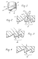
- FIG. 1 shows a lighting fixture 10 according to the invention.
- Lighting fixture 10 includes a housing 11 forming an optical cavity 12 having an optical window 13.
- Lighting fixture 10 further includes a reflective element 14 on a side of housing 11 opposed to optical window 13 and a light source 15.
- Reflective element 14 includes Fresnel-type structures 16 for collimating a portion of the light emitted by light source 15 and otherwise directing the remaining light to desired locations. Because light source 15 acts as a point source, Fresnel-type structures 16 are circular and concentric centered around light source 15. Alternatively, if a linear light source was used, the Fresnel-type structures should be linear and run parallel to the main axis of the light source.
- Fresnel-type structures 16 are arranged in three concentric groups.
- Figure 2 illustrates the structure of the Fresnel-type structures of the first group.
- Reflective element 14 comprises a transparent film 17, typically of a polymer material, and a reflective coating 18, typically of vacuum deposited metal.
- the Fresnel-type structures are provided on the rear surface of the reflector. None in the invention, however, precludes placing the Fresnel-type structures on the first surface.
- Fresnel-type structure 19 of Figure 2 is typical of the Fresnel-type structures of this first group.
- Fresnel-type structure 19 includes a first active face 20, a second active face 22, a third active face 24, and a riser 26.
- First active surface 20 reflects light emitted by light source 15, such as light ray 28, toward the center of the optical window.
- Second active face 22 reflects light, such as light ray 30, to the side in order to discard such light with respect to a viewer observing the light fixture from the front.
- Active face 24 reflects light, as exemplified by light ray 32, in the manner of a conventional Fresnel-type reflector, i.e. mimicking the operation of a reflector having a preselected curvature.
- active face 32 and other similar active faces may be designed to mimic the characteristics of a parabolic reflector.
- a second group of Fresnel-type structures is introduced concentric to and outside of the first group.
- Figure 3 shows a cross-section of the Fresnel-type structures of the second group such as Fresnel-type structure 34.
- Fresnel-type structure 34 includes two active faces, 36 and 38, and a step 40.
- Active face 36 discards unneeded light in a manner similar to active face 22 of Figure 2.
- Active face 38 acts to collimate light striking it in a manner similar to active face 24 of Figure 2.
- Fresnel-type structures 42 have an active face 44 and a riser 46. Active face 44 operates as a conventional Fresnel-type reflector and contributes to the collimated light output of the light fixture without discarding any of the light striking it.
Abstract
Description
- The present invention relates to lighting elements utilizing Fresnel-type reflectors.
- A common type of lighting fixture utilizes a light source with a reflecting element to produce a collimated or partially collimated beam of light. The reflective element may be spherical or parabolic in shape or may utilize Fresnel-type structures to simulate the operation of such reflectors. Typically the light source is mounted at the optical center of such a reflective element.
- A problem common to such reflectors relates to the mounting of the light source. Because the light source is typically mounted in a fixture that extends through the reflective element, no reflections occur from directly behind the light source. As a result the light fixture does not produce uniform brightness over its entire surface. It will actually appear dimmer in the region closest to the light source. Furthermore surrounding the central dark region will be a bright band. The apparent brightness will then become progressively less toward the outer portions of the fixture. Thus such a light fixture will appear to have significant nonuniformities in brightness, with darker regions in the areas nearest to and farthest from the optical center of the light fixture.
- Another problem with such lighting fixtures arises in their very common usage in automotive applications. Many countries have limitations on the amount or brightness of light emitted in particular directions by various lights on an automobile. For example "fill lights" between the headlights of a car must not emit more than a specified amount of light in a forward direction. This is to prevent obscuring the view of oncoming motorists. Some of the most reliable light sources, however, will exceed such safety standards if the efficiency of the reflector is too great. The efficiency of the reflector may be reduced by darkening portions thereof or by reducing the specular reflectivity of the mirror. Both of these solutions, however, tend to produce lighting fixtures that are less aesthetically pleasing.
- In the present invention a reflector is provided with a plurality of Fresnel-type structures. At least some of those Fresnel-type structures have two active faces and a riser. The use of multiple active faces allows light to be directed in different directions in order to provide a uniform level of brightness across a lighting fixture. Some of the active faces may also be used to discord unneeded or unwanted light.
-
- Figure 1 is a view of a lighting fixture according to the invention;
- Figure 2 is a schematic cross-sectional view of a first Fresnel-type structure used in a reflector according to the invention;
- Figure 3 is a schematic cross-sectional view of a second Fresnel-type structure used in a reflector according to the invention; and
- Figure 4 is a schematic cross-sectional view of a third Fresnel-type structure used in a reflector according to the invention.
- Figure 1 shows a lighting fixture 10 according to the invention. Lighting fixture 10 includes a housing 11 forming an
optical cavity 12 having anoptical window 13. Lighting fixture 10 further includes areflective element 14 on a side of housing 11 opposed tooptical window 13 and alight source 15.Reflective element 14 includes Fresnel-type structures 16 for collimating a portion of the light emitted bylight source 15 and otherwise directing the remaining light to desired locations. Becauselight source 15 acts as a point source, Fresnel-type structures 16 are circular and concentric centered aroundlight source 15. Alternatively, if a linear light source was used, the Fresnel-type structures should be linear and run parallel to the main axis of the light source. - In a preferred embodiment Fresnel-
type structures 16 are arranged in three concentric groups. Figure 2 illustrates the structure of the Fresnel-type structures of the first group.Reflective element 14 comprises atransparent film 17, typically of a polymer material, and areflective coating 18, typically of vacuum deposited metal. As may be seen in Figure 2, the Fresnel-type structures are provided on the rear surface of the reflector. Nothing in the invention, however, precludes placing the Fresnel-type structures on the first surface. - In the preferred embodiment the members of the first group are provided in an inner band closest to
light source 15. Fresnel-type structure 19 of Figure 2 is typical of the Fresnel-type structures of this first group. Fresnel-type structure 19 includes a firstactive face 20, a secondactive face 22, a thirdactive face 24, and ariser 26. Firstactive surface 20 reflects light emitted bylight source 15, such aslight ray 28, toward the center of the optical window. Secondactive face 22 reflects light, such aslight ray 30, to the side in order to discard such light with respect to a viewer observing the light fixture from the front.Active face 24 reflects light, as exemplified bylight ray 32, in the manner of a conventional Fresnel-type reflector, i.e. mimicking the operation of a reflector having a preselected curvature. For example,active face 32 and other similar active faces may be designed to mimic the characteristics of a parabolic reflector. - A second group of Fresnel-type structures is introduced concentric to and outside of the first group. Figure 3 shows a cross-section of the Fresnel-type structures of the second group such as Fresnel-
type structure 34. Fresnel-type structure 34 includes two active faces, 36 and 38, and astep 40.Active face 36 discards unneeded light in a manner similar toactive face 22 of Figure 2. Typically a smaller percentage of the light striking the second group of Fresnel-type structures will be discarded than is discarded by the first group of Fresnel-type structures. In this way the apparent brightness of the light fixture is made more nearly constant across its surface.Active face 38 acts to collimate light striking it in a manner similar toactive face 24 of Figure 2. - As the radius of the Fresnel-type structures increases, less of the light needs be discarded in order to maintain a uniform level of brightness across the light fixture. Eventually the radius becomes great enough that none of the light needs to be discarded. Thus a third group of Fresnel-type structures is introduced in the outer region of the reflector. Figure 4 illustrates the Fresnel-type structures of the third group such as Fresnel-
type structure 42. Fresnel-type structure 42 has anactive face 44 and ariser 46.Active face 44 operates as a conventional Fresnel-type reflector and contributes to the collimated light output of the light fixture without discarding any of the light striking it.
Claims (7)
at least some of said Fresnel-type structures comprise two active faces and a riser, one of said active faces being positioned to collimate light from said light source and the other of said active faces being positioned to reflect light from said light source to a location on said optical window adjacent said light source.
at least some of said Fresnel-type structures comprise two active faces and a riser.
Applications Claiming Priority (2)
| Application Number | Priority Date | Filing Date | Title |
|---|---|---|---|
| US07/192,212 US4989125A (en) | 1988-05-10 | 1988-05-10 | Reflector using fresnel-type structures having a plurality of active faces |
| US192212 | 1988-05-10 |
Publications (3)
| Publication Number | Publication Date |
|---|---|
| EP0341996A2 true EP0341996A2 (en) | 1989-11-15 |
| EP0341996A3 EP0341996A3 (en) | 1990-06-27 |
| EP0341996B1 EP0341996B1 (en) | 1993-10-06 |
Family
ID=22708712
Family Applications (1)
| Application Number | Title | Priority Date | Filing Date |
|---|---|---|---|
| EP89304713A Expired - Lifetime EP0341996B1 (en) | 1988-05-10 | 1989-05-10 | Reflector using fresnel-type structures having a plurality of active faces |
Country Status (9)
| Country | Link |
|---|---|
| US (1) | US4989125A (en) |
| EP (1) | EP0341996B1 (en) |
| JP (1) | JPH0218801A (en) |
| KR (1) | KR0147828B1 (en) |
| AU (1) | AU629207B2 (en) |
| BR (1) | BR8902170A (en) |
| CA (1) | CA1332390C (en) |
| DE (1) | DE68909668T2 (en) |
| ES (1) | ES2044107T3 (en) |
Cited By (6)
| Publication number | Priority date | Publication date | Assignee | Title |
|---|---|---|---|---|
| EP0405563A2 (en) * | 1989-06-29 | 1991-01-02 | Dainippon Screen Mfg. Co., Ltd. | Illumination system |
| EP0467608A2 (en) * | 1990-07-17 | 1992-01-22 | Minnesota Mining And Manufacturing Company | Uniform intensity profile catadioptric lens |
| EP0476893A1 (en) * | 1990-09-19 | 1992-03-25 | Minnesota Mining And Manufacturing Company | Uniform intensity profile catadioptric lens |
| EP0678703A1 (en) * | 1994-04-20 | 1995-10-25 | Automotive Lighting Rear Lamps Italia S.p.A. | Light for motor vehicles comprising a reflector including a plurality of reflecting areas |
| WO2005027057A1 (en) * | 2003-09-10 | 2005-03-24 | Giesecke & Devrient Gmbh | Lighting device |
| DE102007002438A1 (en) * | 2007-01-10 | 2008-07-17 | Fresnel Optics Gmbh | Lighting element with reflective Fresnel structure |
Families Citing this family (19)
| Publication number | Priority date | Publication date | Assignee | Title |
|---|---|---|---|---|
| US5243506A (en) * | 1991-06-17 | 1993-09-07 | Tir Systems Ltd. | High aspect ratio light emitter having high uniformity and directionality |
| US5339382A (en) * | 1993-02-23 | 1994-08-16 | Minnesota Mining And Manufacturing Company | Prism light guide luminaire with efficient directional output |
| US5844730A (en) * | 1993-04-07 | 1998-12-01 | Nikon Corporation | Light-supplying optical device |
| DE19521254A1 (en) * | 1994-06-24 | 1996-01-04 | Minnesota Mining & Mfg | Display system with brightness boosting film |
| CN1191507A (en) * | 1995-07-25 | 1998-08-26 | 株式会社小松制作所 | High-speed safety circuit of hydraulic machine |
| US5661839A (en) * | 1996-03-22 | 1997-08-26 | The University Of British Columbia | Light guide employing multilayer optical film |
| JPH1086899A (en) * | 1996-09-17 | 1998-04-07 | Komii Kogei Kk | Monitoring mirror for aircraft passenger cabin |
| US6031958A (en) * | 1997-05-21 | 2000-02-29 | Mcgaffigan; Thomas H. | Optical light pipes with laser light appearance |
| US6024462A (en) * | 1997-06-10 | 2000-02-15 | The University Of British Columbia | High efficiency high intensity backlighting of graphic displays |
| US6079844A (en) * | 1997-06-10 | 2000-06-27 | The University Of British Columbia | High efficiency high intensity backlighting of graphic displays |
| US6166787A (en) * | 1998-03-17 | 2000-12-26 | Motorola, Inc. | Optical display device having prismatic film for enhanced viewing |
| US6285425B1 (en) | 1998-06-29 | 2001-09-04 | Motorola, Inc. | Ridged reflector for an optical display having a curved and a planar facet for each ridge |
| US6285426B1 (en) | 1998-07-06 | 2001-09-04 | Motorola, Inc. | Ridged reflector having optically transmissive properties for an optical display device |
| US6345982B1 (en) * | 1999-09-01 | 2002-02-12 | Darcy M. Dunaway | Dental light controller and concentrator |
| JP4067387B2 (en) * | 2002-11-08 | 2008-03-26 | アルプス電気株式会社 | Light guiding material and lighting device |
| US7088405B2 (en) * | 2003-05-05 | 2006-08-08 | 3M Innovative Properties Company | Structured transflectors for enhanced ambient and backlight operation of transmissive liquid crystal displays |
| US20050237749A1 (en) * | 2004-04-22 | 2005-10-27 | 3M Innovative Properties Company | Transflector |
| CN100439943C (en) * | 2005-07-07 | 2008-12-03 | 香港理工大学 | Light-guiding plate and back-light moudle with same |
| DE102010027028B4 (en) * | 2010-07-14 | 2016-06-02 | Automotive Lighting Reutlingen Gmbh | Automotive lighting device with a reflector homogeneously distributing light |
Citations (2)
| Publication number | Priority date | Publication date | Assignee | Title |
|---|---|---|---|---|
| GB408366A (en) * | 1932-11-09 | 1934-04-12 | Holophane Ltd | Improvements in prismatic lighting units |
| US4081667A (en) * | 1976-07-28 | 1978-03-28 | Optical Coating Laboratory, Inc. | Lighting fixture having fresnel reflector with high reflection coating thereon |
Family Cites Families (14)
| Publication number | Priority date | Publication date | Assignee | Title |
|---|---|---|---|---|
| US1554315A (en) * | 1925-02-26 | 1925-09-22 | Frederick Joseph Green | Reflector for headlights |
| FR696573A (en) * | 1929-06-10 | 1931-01-05 | Improvements to light reflectors | |
| US2421277A (en) * | 1943-05-12 | 1947-05-27 | Richard W Luce | Reflective sign |
| US3710095A (en) * | 1970-09-23 | 1973-01-09 | Gen Motors Corp | Method of making a faceted reflector for a lighting unit |
| US4041306A (en) * | 1975-12-15 | 1977-08-09 | Kim Lighting, Inc. | Luminaire and reflector therefor |
| JPS54161767A (en) * | 1978-06-12 | 1979-12-21 | Ichikoh Ind Ltd | Lamp for automobile |
| JPS54161769A (en) * | 1978-06-12 | 1979-12-21 | Ichikoh Ind Ltd | Lamp for automobile |
| US4360863A (en) * | 1978-06-28 | 1982-11-23 | International Telephone And Telegraph Corporation | Luminaire for residential roadway lighting |
| ZA832713B (en) * | 1982-04-20 | 1984-08-29 | Evans Adlard & Co | Glass fibre paper separator for electrochemical cells |
| FR2525733A1 (en) * | 1982-04-23 | 1983-10-28 | Auteroche Sa | Headlamp reflector with sub-reflector to aim beam downwards - uses main reflector with stepped parabolic segments moulded in to deflect down part of light beam |
| JPS60163701A (en) * | 1984-02-06 | 1985-08-26 | Tokai Rika Co Ltd | Rotating body with display |
| FR2580782B1 (en) * | 1985-04-22 | 1987-07-10 | Cibie Projecteurs | ROAD PROJECTOR FOR A MOTOR VEHICLE INCORPORATING AN ELLIPTICAL REFLECTOR AND A PARABOLIC REFLECTOR |
| DE3669578D1 (en) * | 1985-08-06 | 1990-04-19 | Awa Ltd | LENS FOR TRAFFIC LAMP. |
| US4704661A (en) * | 1986-08-25 | 1987-11-03 | General Electric Company | Faceted reflector for headlamps |
-
1988
- 1988-05-10 US US07/192,212 patent/US4989125A/en not_active Expired - Lifetime
-
1989
- 1989-04-27 AU AU33793/89A patent/AU629207B2/en not_active Ceased
- 1989-05-05 CA CA000598802A patent/CA1332390C/en not_active Expired - Fee Related
- 1989-05-09 JP JP1115930A patent/JPH0218801A/en active Pending
- 1989-05-09 BR BR898902170A patent/BR8902170A/en unknown
- 1989-05-09 KR KR1019890006163A patent/KR0147828B1/en not_active IP Right Cessation
- 1989-05-10 EP EP89304713A patent/EP0341996B1/en not_active Expired - Lifetime
- 1989-05-10 DE DE89304713T patent/DE68909668T2/en not_active Expired - Fee Related
- 1989-05-10 ES ES89304713T patent/ES2044107T3/en not_active Expired - Lifetime
Patent Citations (2)
| Publication number | Priority date | Publication date | Assignee | Title |
|---|---|---|---|---|
| GB408366A (en) * | 1932-11-09 | 1934-04-12 | Holophane Ltd | Improvements in prismatic lighting units |
| US4081667A (en) * | 1976-07-28 | 1978-03-28 | Optical Coating Laboratory, Inc. | Lighting fixture having fresnel reflector with high reflection coating thereon |
Cited By (9)
| Publication number | Priority date | Publication date | Assignee | Title |
|---|---|---|---|---|
| EP0405563A2 (en) * | 1989-06-29 | 1991-01-02 | Dainippon Screen Mfg. Co., Ltd. | Illumination system |
| EP0405563A3 (en) * | 1989-06-29 | 1992-03-04 | Dainippon Screen Mfg. Co., Ltd. | Illumination system |
| EP0467608A2 (en) * | 1990-07-17 | 1992-01-22 | Minnesota Mining And Manufacturing Company | Uniform intensity profile catadioptric lens |
| EP0467608A3 (en) * | 1990-07-17 | 1992-04-22 | Minnesota Mining And Manufacturing Company | Uniform intensity profile catadioptric lens |
| EP0476893A1 (en) * | 1990-09-19 | 1992-03-25 | Minnesota Mining And Manufacturing Company | Uniform intensity profile catadioptric lens |
| EP0678703A1 (en) * | 1994-04-20 | 1995-10-25 | Automotive Lighting Rear Lamps Italia S.p.A. | Light for motor vehicles comprising a reflector including a plurality of reflecting areas |
| WO2005027057A1 (en) * | 2003-09-10 | 2005-03-24 | Giesecke & Devrient Gmbh | Lighting device |
| US7600898B2 (en) | 2003-09-10 | 2009-10-13 | Giesecke & Devrient Gmbh | Illuminating device for linearly illuminating a flat object |
| DE102007002438A1 (en) * | 2007-01-10 | 2008-07-17 | Fresnel Optics Gmbh | Lighting element with reflective Fresnel structure |
Also Published As
| Publication number | Publication date |
|---|---|
| BR8902170A (en) | 1990-01-02 |
| EP0341996B1 (en) | 1993-10-06 |
| DE68909668T2 (en) | 1994-04-28 |
| ES2044107T3 (en) | 1994-01-01 |
| KR0147828B1 (en) | 1998-10-01 |
| DE68909668D1 (en) | 1993-11-11 |
| US4989125A (en) | 1991-01-29 |
| KR890017487A (en) | 1989-12-16 |
| AU629207B2 (en) | 1992-10-01 |
| CA1332390C (en) | 1994-10-11 |
| AU3379389A (en) | 1989-11-16 |
| EP0341996A3 (en) | 1990-06-27 |
| JPH0218801A (en) | 1990-01-23 |
Similar Documents
| Publication | Publication Date | Title |
|---|---|---|
| EP0341996B1 (en) | Reflector using fresnel-type structures having a plurality of active faces | |
| US4799131A (en) | Automotive lighting element | |
| US5054885A (en) | Light fixture including a partially collimated beam of light and reflective prisms having peaks lying on a curved surface | |
| US4874228A (en) | Back-lit display | |
| US5762414A (en) | Indicating light, in particular a complementary stop light for a motor vehicle, having a number of light sources in line with each other | |
| JPH0758362A (en) | Optical system for light emitting diode | |
| US5097395A (en) | Multiple cavity light fixture | |
| JPH09167515A (en) | Peripheral optical element for changing direction of light beam from led | |
| US6224246B1 (en) | Signal lamp for vehicles | |
| AU633845B2 (en) | Light fixture | |
| JPH09180514A (en) | Display for automobile | |
| US4985814A (en) | Warning light with quadruple reflective surfaces | |
| JP2693173B2 (en) | Light fixtures | |
| EP1363067A2 (en) | Vehicle lamp with visor | |
| US6637918B2 (en) | Lighting or indicator device for a motor vehicle | |
| US6796694B2 (en) | Vehicular signal lamp | |
| EP0470752A1 (en) | Lamps | |
| US7420173B2 (en) | Reflective collimation optic | |
| JP3124235B2 (en) | Vehicle lighting | |
| EP0971166A2 (en) | Motor-vehicle light having segmented fresnel lenses | |
| JP3331579B2 (en) | Reflective surface structure of vehicle lighting | |
| JP3010528B2 (en) | Lamp | |
| JP2000173312A (en) | Lamp for vehicle | |
| JP2522999Y2 (en) | Body color lighting lens | |
| JP2001216817A (en) | Lighting fixture for vehicle |
Legal Events
| Date | Code | Title | Description |
|---|---|---|---|
| PUAI | Public reference made under article 153(3) epc to a published international application that has entered the european phase |
Free format text: ORIGINAL CODE: 0009012 |
|
| AK | Designated contracting states |
Kind code of ref document: A2 Designated state(s): DE ES FR GB IT SE |
|
| PUAL | Search report despatched |
Free format text: ORIGINAL CODE: 0009013 |
|
| AK | Designated contracting states |
Kind code of ref document: A3 Designated state(s): DE ES FR GB IT SE |
|
| 17P | Request for examination filed |
Effective date: 19901002 |
|
| 17Q | First examination report despatched |
Effective date: 19921113 |
|
| GRAA | (expected) grant |
Free format text: ORIGINAL CODE: 0009210 |
|
| ITF | It: translation for a ep patent filed |
Owner name: BARZANO' E ZANARDO ROMA S.P.A. |
|
| AK | Designated contracting states |
Kind code of ref document: B1 Designated state(s): DE ES FR GB IT SE |
|
| REF | Corresponds to: |
Ref document number: 68909668 Country of ref document: DE Date of ref document: 19931111 |
|
| REG | Reference to a national code |
Ref country code: ES Ref legal event code: FG2A Ref document number: 2044107 Country of ref document: ES Kind code of ref document: T3 |
|
| ET | Fr: translation filed | ||
| PG25 | Lapsed in a contracting state [announced via postgrant information from national office to epo] |
Ref country code: SE Effective date: 19940511 Ref country code: ES Free format text: LAPSE BECAUSE OF NON-PAYMENT OF DUE FEES Effective date: 19940511 |
|
| PLBE | No opposition filed within time limit |
Free format text: ORIGINAL CODE: 0009261 |
|
| STAA | Information on the status of an ep patent application or granted ep patent |
Free format text: STATUS: NO OPPOSITION FILED WITHIN TIME LIMIT |
|
| 26N | No opposition filed | ||
| EUG | Se: european patent has lapsed |
Ref document number: 89304713.4 Effective date: 19941210 |
|
| EUG | Se: european patent has lapsed |
Ref document number: 89304713.4 |
|
| REG | Reference to a national code |
Ref country code: ES Ref legal event code: FD2A Effective date: 19990301 |
|
| REG | Reference to a national code |
Ref country code: GB Ref legal event code: IF02 |
|
| PGFP | Annual fee paid to national office [announced via postgrant information from national office to epo] |
Ref country code: FR Payment date: 20020417 Year of fee payment: 14 |
|
| PGFP | Annual fee paid to national office [announced via postgrant information from national office to epo] |
Ref country code: GB Payment date: 20020501 Year of fee payment: 14 |
|
| PG25 | Lapsed in a contracting state [announced via postgrant information from national office to epo] |
Ref country code: GB Free format text: LAPSE BECAUSE OF NON-PAYMENT OF DUE FEES Effective date: 20030510 |
|
| GBPC | Gb: european patent ceased through non-payment of renewal fee |
Effective date: 20030510 |
|
| PG25 | Lapsed in a contracting state [announced via postgrant information from national office to epo] |
Ref country code: FR Free format text: LAPSE BECAUSE OF NON-PAYMENT OF DUE FEES Effective date: 20040130 |
|
| REG | Reference to a national code |
Ref country code: FR Ref legal event code: ST |
|
| PG25 | Lapsed in a contracting state [announced via postgrant information from national office to epo] |
Ref country code: IT Free format text: LAPSE BECAUSE OF NON-PAYMENT OF DUE FEES;WARNING: LAPSES OF ITALIAN PATENTS WITH EFFECTIVE DATE BEFORE 2007 MAY HAVE OCCURRED AT ANY TIME BEFORE 2007. THE CORRECT EFFECTIVE DATE MAY BE DIFFERENT FROM THE ONE RECORDED. Effective date: 20050510 |
|
| PGFP | Annual fee paid to national office [announced via postgrant information from national office to epo] |
Ref country code: DE Payment date: 20070702 Year of fee payment: 19 |
|
| PG25 | Lapsed in a contracting state [announced via postgrant information from national office to epo] |
Ref country code: DE Free format text: LAPSE BECAUSE OF NON-PAYMENT OF DUE FEES Effective date: 20081202 |