EP0342958A2 - High efficiency cube-corner retroreflective material - Google Patents
High efficiency cube-corner retroreflective material Download PDFInfo
- Publication number
- EP0342958A2 EP0342958A2 EP89304988A EP89304988A EP0342958A2 EP 0342958 A2 EP0342958 A2 EP 0342958A2 EP 89304988 A EP89304988 A EP 89304988A EP 89304988 A EP89304988 A EP 89304988A EP 0342958 A2 EP0342958 A2 EP 0342958A2
- Authority
- EP
- European Patent Office
- Prior art keywords
- elements
- grooves
- cube
- angle
- faces
- Prior art date
- Legal status (The legal status is an assumption and is not a legal conclusion. Google has not performed a legal analysis and makes no representation as to the accuracy of the status listed.)
- Granted
Links
Images


Classifications
-
- G—PHYSICS
- G02—OPTICS
- G02B—OPTICAL ELEMENTS, SYSTEMS OR APPARATUS
- G02B1/00—Optical elements characterised by the material of which they are made; Optical coatings for optical elements
- G02B1/10—Optical coatings produced by application to, or surface treatment of, optical elements
- G02B1/12—Optical coatings produced by application to, or surface treatment of, optical elements by surface treatment, e.g. by irradiation
-
- G—PHYSICS
- G02—OPTICS
- G02B—OPTICAL ELEMENTS, SYSTEMS OR APPARATUS
- G02B5/00—Optical elements other than lenses
- G02B5/12—Reflex reflectors
- G02B5/122—Reflex reflectors cube corner, trihedral or triple reflector type
- G02B5/124—Reflex reflectors cube corner, trihedral or triple reflector type plural reflecting elements forming part of a unitary plate or sheet
-
- Y—GENERAL TAGGING OF NEW TECHNOLOGICAL DEVELOPMENTS; GENERAL TAGGING OF CROSS-SECTIONAL TECHNOLOGIES SPANNING OVER SEVERAL SECTIONS OF THE IPC; TECHNICAL SUBJECTS COVERED BY FORMER USPC CROSS-REFERENCE ART COLLECTIONS [XRACs] AND DIGESTS
- Y10—TECHNICAL SUBJECTS COVERED BY FORMER USPC
- Y10S—TECHNICAL SUBJECTS COVERED BY FORMER USPC CROSS-REFERENCE ART COLLECTIONS [XRACs] AND DIGESTS
- Y10S359/00—Optical: systems and elements
- Y10S359/90—Methods
Definitions
- the present invention is directed to cube-corner retroreflective articles, particularly to such articles which are efficient at high incidence angles and which may be tailored so as to distribute light retroreflected by the material into a desired pattern or divergence profile.
- Cube-corner reflecting elements are trihedral structures which have three mutually perpendicular lateral faces meeting at a single corner, such as that configuration defined by the corner of a room or a cube.
- the retroreflectivity typically achieved by cube-corner type reflecting elements is through the principle of total internal reflection.
- a transparent cube-corner element receives a ray of incident light at an angle and sends it back in the same direction. See, for example, U.S. Patent Nos. 3,924,929, 4,672,089, 4,349,598, and 4,588,258.
- the light reflected by retroreflective articles back toward the source of the light has generally been spread into a cone-like pattern centered on the path the light traveled to the reflector; such a spreading has been necessary so that, for example, light from the headlamps of an oncoming vehicle, reflected back toward the vehicle by a retroreflective sign, will diverge sufficienty to reach the eyes of the driver, who is positioned off-axis from the headlamp beam.
- the spreading of light from cube-corner retroreflective articles has deficiencies: the cone of retroreflected light is often too narrow for many uses that require reflected light to be seen farther off-axis; and the three-sided nature of the cube-corner retroreflective elements gives the retroreflected cone of light an undesirable asymmetric shape, with the result that cube-corner retroreflective articles suffer from a variation in retroreflective brightness when viewed from different presentation angles (a glossary of terms is at the end of the specification).
- These deficiencies can be sufficiently severe that two persons sitting side-by-side in a vehicle passing a sign covered with cube-corner retroreflective sheeting may have distinctly different perceptions as to the brightness of the sign.
- U.S. Patent No. 3,817,596 increases the divergence or spreading of light rays from a cube-corner retroreflective article by deliberately tilting the faces of the cube-corner retroreflective elements out of perpendicularity or orthogonality.
- U.S. Patent No. 3,833,285 (Heenan) changes the divergence or spreading of light from a cube-corner retroreflective article in a different manner, specifically by incorporating into the article a set of special cube-corner retroreflective elements arranged in a row.
- a disadvantage of a retroreflective article as taught in U.S. Patent No. 3,833,285 is the fact that, in many retroreflective articles, such as traffic control signs, it could be distracting to have a single isolated row of retroreflective elements that distributes light in patterns that are noticeably different from those of other retroreflective elements of the article. For example, instead of seeing a uniformly lit retroreflective sign, an observer would see variations in brightness that could distract from an understanding of the information carried on the sign. Further, a product as described in U.S. Patent No. 3,833,285 required the precise manufacture of individual pins that are subsequently bundled together to form the row of elements, and it is difficult to precisely form and group together such distinct pins to obtain retroreflection within desired tolerances.
- a need exists for an improved retroreflective material which may be individually tailored so as to distribute light retroreflected by the material into a desired pattern or divergence profile and which is efficient at high angles of incidence.
- the present invention provides a retroreflective material which is efficient at high angles of incidence and which may be individually tailored so as to distribute light retroreflected by the material into a desired pattern or divergence profile.
- the retroreflective material of the present invention comprises a transparent surface layer having a front side and a back side and an array of cube-corner reflective elements, each of the reflecting elements including a rectangular base on the back side of the surface layer, two rectangular faces nearly perpendicular to each other each one being joined to an edge of the rectangular base to form a reflecting element having a triangular cross section, and two triangular faces that are approximately parallel to each other and approximately perpendicular to the rectangular faces, and forming the ends of the reflecting elements; and the triangular and rectangular faces defining a pair of approximate cube-corners therebetween, the reflecting elements arranged with their bases adjacent to the surface layer.
- the terms "approximately parallel” and “approximately perpendicular” are used herein to refer to faces which are truly parallel or perpendicular and faces which have small variations from true parallelism or perpendicularity.
- the reflecting elements are formed by two perpendicular intersecting sets of parallel grooves, the first set being V-shaped, and the second set of grooves each having a pair of faces each of which is nearly perpendicular to the rectangular base.
- the first set of grooves forms the rectangular faces and the second set of grooves forms the triangular faces of the reflecting elements.
- At least one of the sets of grooves includes more than one groove having a groove side angle that differs from another groove side angle of the same set by a small amount (less than 3°, usually less than 1°).
- the cube-corner retroreflective elements have small variations in at least one of the dihedral angles between the faces from one reflecting element to another, the variations existing in at least some but not necessarily all of the reflecting elements.
- the cube-corner retroreflective elements of a plurality of distinct shapes.
- At least one of the distinctive shapes is for a nonorthogonal cube-corner retroreflective element, by which it is meant that at least one face of the element is tilted at an angle that differs from the angle which would be required for all dihedral angles within the element to be orthogonal; even though the dihedral angles are not all orthogonal, such an element is still regarded as a cube-corner retroreflective element herein, because it closely resembles the ideal cube-corner retroreflective element in shape and function.
- the distinctively shaped cube-corner retroreflective elements retroreflect incident light in distinctively shaped light patterns.
- the overall pattern of the light retroreflected by an article of the invention i.e., divergence profile for the article, can be designed by specifying the variations in groove side angles.
- a practical benefit for signs is that they can be designed with a divergence profile that returns the light to the observer area, rather than back into the headlights of his car. That is, the divergence profile can be spread out.
- the array of reflecting elements is divided into repeating sub-arrays that each comprise a plurality of cube-corner reteroreflective elements of a plurality of different shapes.
- the divergence profile comprises a summation of the different light patterns in which the distinctively shaped cube-corner retroreflective elements in a sub-array retroreflect incident light, and the individual distinctive shaped light patterns can be selected to give the overall pattern a desired shape.
- the present invention also provides a method for preparing a tool from which cube-corner retroreflective articles are formed, comprising forming in tool stock at least one set of parallel grooves that define at least some lateral faces of the cube-corner elements, at least one of the grooves being varied to an angle different by a predetermined small amount from the angle required to provide orthogonal cube-corner elements.
- a representative retroreflective sheet material 10 manufactured from tooling made by the method of the invention is shown from the back of the sheet material in Fig. 1 and in section in Fig. 2.
- the configured back surface of the sheet material 10 is defined by three intersecting sets 11, 12, and 13 of parallel V-shaped grooves which form a dense or fully packed array of cube-corner retroreflective elements.
- the angles for the sides of the grooves i.e., the groove side angles, are chosen so that the dihedral angles formed at the lines of intersection of the grooves, e.g, the lines 14, 15 and 16 for the representative cube-corner retroreflective element 17 in Fig. 1, are approximately 90 o .
- At least one of the intersecting sets of parallel grooves includes, in a repeating pattern, grooves having one or both groove side angles different from at least one other groove side angle of the same set.
- repeating pattern it is meant that a particular distinctive groove side angle(s) occurs periodically across the array of cube-corner retroreflective elements, i.e., is spaced the same number of grooves from its previously occurring position in the array.
- Fig. 2 shows part of a representative set of grooves having groove side angles that differ in an exaggerated manner from other groove side angles of the same set.
- Fig. 2 shows a set of grooves 13 from the sheet material of Fig. 1, i.e., 131, 132, 133, and 134.
- this set of grooves there are four different groove side angles "a,” “b,” “c,” and “d,” extending between the sides of the grooves and a plane 18 that is perpendicular to a plane defined by the bottom edges 19 of the grooves.
- the present invention also includes configurations wherein the bottom edges of the grooves are not coplanar.
- the groove side angles are arranged in an a-b-c-d-a-b-c-d repeating pattern.
- the groove side angle "a" in this representative set is an angle that would form an orthogonal dihedral angle at the intersection of the groove side with groove sides of the other two sets of grooves (such groove side angles are sometimes termed "orthogonal-producing” herein), and the groove side angles "b,” “c,” and “d” do not produce orthogonal dihedral angles.
- the position of the groove sides that would be orthogonal-producing is shown in dotted lines in Fig. 2, and as will be seen, the angle "b” is less than that needed to obtain orthogonality, and the angles "c” and "d” are larger than that needed to obtain orthogonality.
- Figs. 3 and 4 show in schematic plan view representative patterns of grooves for a retroreflective article manufactured from tooling made by the method of the invention.
- each line represents one V-shaped groove, with the letter on each side of a line representing the groove side angle on that side of the groove.
- each of the three sets of grooves can have a different repeating pattern of groove side angles.
- one set has an a-b-b-a pattern
- a second set has an a-b-a-b-b-a-b-a pattern
- the third set has a c-d-e-f-d-c-f-e pattern.
- the different grooving patterns are, respectively, an a-b-b-a pattern, an a-b-a-b-b-a-b-a pattern, and a c-d-d-c pattern.
- a retroreflective material 110 of the present invention is shown having reflecting elements 120.
- Reflecting elements 120 include a rectangular base 122, a pair of rectangular faces 124 and 126 and a pair of approximately perpendicular triangular faces 128 and 129.
- the triangular faces 128 and 129 lie nearly perpendicular to the base 122.
- the rectangular base is less than or equal to 0.5 millimeter long, and the intersection of the rectangular faces 124 and 126 is less than 0.2 millimeter from the base.
- the rectangular faces 124 and 126 and the triangular faces 128 and 129 form cube-corners 130 and 132 as will be discussed in greater detail herein.
- the cube-corners 130 and 132 are referred to as cube-corners regardless of whether they are orthogonal or nonorthogonal cube-corners.
- the reflecting elements 120 are uniformly arranged in rows, as shown in Fig. 5, with the triangular faces 128 adjacent to the triangular faces 129 of neighboring reflecting elements 120.
- the rectangular faces 124 and 126 form a first v-shaped groove 134.
- the triangular faces 128 and 129 form a second groove 136 having as its approximately perpendicular faces the triangular faces 128 and 129.
- the first groove 134 and the second groove 136 are perpendicular to each other, as shown in Fig. 5.
- the retroreflective elements 120 are formed on the back side of a transparent surface layer 140.
- the elements 120 are attached to a backing material 160 which has an adhesive layer 162, which is used to attach the retroreflective material 110 to a signing material 164.
- This retroreflector is like that of U.S. Patent No. 4,349,598 (White) (which is incorporated by reference herein), with an important difference. Namely, the dihedral angles of at least some of the cube-corner elements are not 90°, but some angle slightly different from 90°, by a difference of less than 1° usually. The amount of this difference varies so that, for example, one cube-corner element may have a dihedral angle of 90°30′ and the one next to it may have an 89°50′ angle. There is a plurality of such variations in the retroreflector which is said to be multi-nonorthoganal. This feature helps to alleviate variations in the brightness of reflected light across the area of the retroreflector, and it results from variations in the grooves which form the cube-corner elements.
- the groove side angles of the first V-shaped groove 134 are approximately 45 o .
- the groove side angles of the second groove 136 which has approximately perpendicular sides is approximately 0 o .
- at least one of the intersecting sets of parallel grooves includes, preferably in a repeating pattern, grooves having one or both groove side angles different from at least one other groove side angle of the same set.
- Each retroreflective element of the sheet material of the invention has two cube-corners. In some cases both cube-corners will be identical, whereas in other situations the cube-corners may be slightly different from one another with one or both of the cube-corners being non-orthogonal.
- Fig. 6 shows part of a representative set of grooves having groove side angles that differ in an exaggerated manner from other groove side angles of the same set. These grooves will be referred to as right angle channel cross section grooves, since they look approximately like the cross section of a channel having right angle corners or sides perpendicular to the bottom.
- Fig. 6 shows a set of grooves 136 from the sheet material of Fig. 5, i.e. 1361, 1362, 1363, and 1364.
- this set of grooves there are three different groove side angles "g", "h”, and "i", extending between the sides of the grooves and a plane 139 that is perpendicular to a plane defined by the bottom edges 137 of the grooves.
- the groove side angles are arranged in an g-h-i-g-i-h-g-h repeating pattern.
- the groove side angle "g" in this representative set is an angle that would, in this representative article, form an orthogonal dihedral angle at the intersection of the groove side with a groove of the other set of V-shaped grooves.
- the groove side angles "h”, and “i” do not produce orthogonal dihedral angles.
- the position of the groove sides that would be orthogonal-producing is shown in dotted lines in Fig. 6.
- the angles "h” and "i" are larger than needed to obtain orthogonality.
- the groove side angles of the set of V-grooves in an article of the present invention can be varied as described above in the discussion about Fig. 2.
- an orthogonal cube-corner would be formed by the intersection of two groove side angles "a", of Fig. 2, and a groove side angle "g" in Fig. 6.
- Fig. 5 also shows a representative pattern of grooves for a retroreflective article of the invention.
- each horizontal line at the left side of the figure represents one V-shaped groove with the letter on each side of a line representing the groove side angle on that side of the groove.
- the pairs of vertical lines each represent a second groove having approximately perpendicular sidewalls, with the letter on each side of a line representing the groove side angle on that side of the groove.
- each of the two sets of grooves can have a different repeating pattern of groove side angles.
- first groove set has a "a-b-b-a” pattern
- the second set has a "g-h-i-g-i-h-g-h” pattern.
- the preferred repeating patterns of grooves form periodically repeating groupings of cube-corner retroreflective elements, or sub-arrays, distributed across one large-area side of the retroreflective article.
- sub-arrays consisting of potentially six distinctive cube-corner retroreflective elements are formed; i.e., assuming a, b, g, h, i are all different from one another, there are six cube-corner retroreflective elements of distinctive shape in the sub-array.
- groove side angles can be repeated more irregularly e.g. 4, 6, and then 5 grooves between recurrences of a given side angle.
- a particular nonorthogonal groove side angle will be repeated numerous times (e.g., 10 or even 100 times or more).
- a large number of the groove side angles e.g., one-third or more
- a particular groove side angle will usually be repeated within a rather short span of grooves, e.g., within a span of 10 or less grooves.
- groove side angles may be adjusted or chosen independently from one another, there need not be pairs of elements, but instead, if desired, the elements can all be different from one another.
- the pairs of elements for the array of Fig. 5 occur because of the particular repeating patterns of grooves used in the array, e.g., by the rotation of the a-b pattern to a b-a pattern in an adjacent groove so that each element is matched by a similarly shaped element rotated 180° from the first element. Whatever repeating patterns are used, so long as the patterns are periodic, the sub-arrays will all be identical to one another.
- c and e could be identical to one another, or other groove side angles could be identical.
- at least one of the two sets of grooves, and for greater control at least two of the sets of grooves (2 of 2 or 2 of 3) include at least one groove side angle that differs from at least one other groove side angle in the same set, with the result that a plurality (i.e., at least two) of the cube-corner retroreflective elements in a sub-array are distinctively shaped, i.e., have a shape different from one another.
- This difference in shape is more than simply a rotation of an element about its axis, such as the 180° rotation noted above or the similar 180° rotation of the cube-corner elements of U.S. Patent No. 4,588,258, but instead arises, for example, because a particular face of a cube-corner element is not orthogonal-producing.
- the individual groove side angles in each repeating pattern may be such as to produce orthogonality or non-orthogonality, though as noted, there will be at least one groove side angle in at least one set that is different from another groove side angle in the set, meaning that there must be at least one groove side angle in the set that is not orthogonal-producing.
- the amount of excess or deficiency from an angle that would be orthogonal-producing is generally a few arc-minutes, i.e., about 15-30 arc-minutes or less, though larger deviations can be used.
- the chosen groove side angles are obtained in the tooling from which articles of the invention are molded to within plus-or-minus about one-half arc-minute, and more preferably, plus-or-minus one-fourth arc-minute. Some further deviation may occur during the molding operation, though preferably there is no more than a two or three arc-minute change, and more preferably, no more than one or two arc-minutes change, during molding.
- the technique of forming a master for cube-corner retroreflectors by cutting intersecting sets of parallel grooves in a flat metal surface with a V-shaped diamond tool is disclosed in U.S. Patent No. 3,712,706, see for example column 3, lines 35-54, column 4, line 57-column 5, line 24, and column 17, line 25-column 22, line 47, all of which are incorporated herein by reference.
- An advantage of the method of the invention is that when cutting a groove, all of the faces produced along each side of the groove have precisely the same angle. Also, this same face angle can be obtained quite precisely each time that the cutting tool is indexed over to repeat the same groove.
- This precision in the shaping of identical cube-corner retroreflective elements allows for a precise overlapping of the retroreflective light patterns from each cube-corner retroreflective element and, therefore, minimizes the divergence or discrepancy between cube-corner elements having the same optical design.
- Such interactive precision contributes to the controlled use of light so that light is directed only at intended angles.
- the grooves forming the configured surface of a retroreflective article of the invention extend continuously across a multitude of sub-arrays, with the many individual sub-arrays being created by the repeating pattern of the grooves.
- Such continuous grooves contrast with the formation of individual pins, each having the shape of an individual cube-corner retroreflective element, such as is used with large cube-corner retroreflective elements, see U.S. Patent No. 3,833,285 (Heenan), and also contrast with the procedure taught in U.S. Patent No.
- the variation from orthogonality in a groove may be obtained by tilting or offsetting a V-shaped tool, such as a diamond-pointed tool, used to form a groove.
- a V-shaped tool such as a diamond-pointed tool
- the same tool may also be used to cut more than one set of grooves.
- the grooves having nearly perpendicular sides may be cut in a similar fashion.
- FIG. 8 shows a fragmentary plan view of the embodiment of Fig. 9.
- a retroreflective material 170 which permits improved angularity in the horizontal direction, is shown.
- Such improved angularity is important, for example, in pavement markers, or vertical barrier delineators.
- Retroreflective material with low angularity will only brightly retroreflect light that impinges on it within a narrow angular range centering approximately on its optical axis.
- the incident angle is the angle between the line of the light beam of the car headlights and a line perpendicular to the reflective sheeting surface in the pavement marker and the plane of the incident angle is defined by those two lines.
- Angularity is a property of the sheeting defined as the largest angle away from a line perpendicular to the reflecting surface of the pavement marker at which the marker will remain an effective retroreflector.
- FIG. 9 reflecting elements 172 and 174 having a base 171 are shown.
- Element 172 has a pair of tetragonal faces 176A and 176B which intersect to define a substantially perpendicular angle.
- a bisector 178 bisects the angle between the faces 176 and intersects the base 171 at a substantially perpendicular angle. This is a construction similar to that shown in Figs. 5-7 and will sometimes be referred to herein as perpendicular bisector elements.
- the element 174 has a pair of tetragonal faces 180A and 180B which intersect to define a substantially perpendicular angle which has a bisector 182.
- the bisector 182 intersects the base 171 at an angle other than substantially 90°.
- the angle, Beta is the angle between a line perpendicular to the base 171 and the bisector 182. Elements such as these will sometimes be referred to as canted bisector elements.
- a retroreflective material designed to have improved angularity may include elements, some or all of which are canted bisector elements such as element 174.
- the angle, Beta can, for example, be the same angle for all of the elements, can be varied randomly, can be varied uniformly, or can be designed in a number of repeating or random patterns for the particular end use.
- a master mold is made by cutting a first groove with an approximately 90° included angle tool.
- the 90° included angle tool is angularly symmetric (45° of the groove on each side of the perpendicular) for some cuts (perpendicular bisector elements) and positioned at varying degrees of asymmetry for others (canted bisector elements).
- the angle, Beta, or the angle from the perpendicular at which the bisector is canted is typically about 0° to less than about 45° and preferably about 0° to about 35°.
- the amount of cant of the bisector corresponds to the increase in angularity in the direction of the cant.
- the mold After the mold is cut it then serves as a master mold for the manufacture of negative molds.
- Duplicates of the master mold can be made from the negative molds by electroforming or other well-known techniques for mold duplication.
- a transparent plastic film or sheet may then be pressed against the duplicate mold or die to form or emboss in the film or sheet the pattern of the master mold.
- a liquid film forming material could be cast onto the mold.
- the base portion of the film or sheet which does not receive the mold impression then serves as a transparent cover sheet for the resulting retroreflective material.
- the composite of reflecting elements and transparent cover sheet is preferably backed with a layer of material to strengthen the composite and to protect the reflective elements from dirt and moisture.
- the backing layer is an opaque thermoplastic film or sheet, preferably one having good weathering properties.
- Suitable materials typically have thicknesses about equal to the thickness of the reflecting elements. Other thicknesses are also suitable, depending on the degree of flexibility desired.
- the backing film or sheet may be sealed in a grid pattern or in any other suitable configuration to the reflecting elements. Sealing may be effected by use of a number of methods, including ultrasonic welding, adhesives, or by heat sealing at discrete locations on the array of reflecting elements (see, for example, U.S. Patent No. 3,924,928). Sealing is important to prevent entry of soil and moisture and to preserve the air spaces around the cube-corner reflecting surfaces.
- the retroreflecting elements may be metalized. If the elements are metalized the air spaces around the elements are not important, as the metal reflects the light. For durability, it is desirable to cover the metal layer with a protective, typically polymeric, layer.
- backing sheets of polycarbonate, polybutyrate or fiber-reinforced plastic may be used.
- the material may be rolled or cut into strips or other suitable designs.
- the retroreflective material may also be backed with an adhesive and release sheet to render it useful for application to any substrate without the added step of applying an adhesive or using other fastening means.
- Groove Side Angle The angle between the groove side and a plane extending parallel to the length of the groove and perpendicular to a plane defined by the bottom of the sets of grooves. Where the bottoms of the grooves are not co-planar, the plane of reference is the front side of the transparent surface layer or the surface where light enters the retroreflective material.
- Reference Center - A point on or near a retroreflector which is designated to be the center of the device for the purpose of specifying its performance.
- Illumination Axis - A line segment from the reference center to the center of the illumination source.
- Observation Angle The angle between the illumination axis and the observation axis.
- Reference Axis - A designated line segment from the reference center which is used to describe the angular position of the retroreflector, and which for most articles, including sheet material of the invention, is a line perpendicular to the front surface of the article.
- Entrance Angle The angle between the illumination axis and the reference axis.
- Observation Half-Plane The half-plane that originates on the illumination axis and which contains the observation axis.
- Second Axis An axis through the reference center and perpendicular to both the first axis and the reference axis.
- Rotation Angle The dihedral angle from the half-plane originating on the reference axis and containing the positive part of the second axis (i.e., the part of the second axis that is in the observation half-plane) to the half-plane originating on the reference axis and containing the datum mark.
- the rotation angle and presentation angle represent the same motion when the datum mark is aligned vertically with the reference center of the article, the receptor or viewer is aligned vertically with the illumination axis, and the illumination axis is perpendicular to the front surface of the article.
- Sheeting of the invention having improved rotational symmetry is of advantage since it minimizes the differences in divergence profile caused by mounting the sheeting in different angular orientations.
- Observation Profile or Viewing Profile - A polar plot similar to that for the divergence profile but which defines the range of viewing positions contemplated for a viewer with respect to a retroreflective article of the invention. Ideally, the divergence profile for a retroreflective article would match the contemplated observation or viewing profile.
- divergence profile is generally used herein when emphasis is on the pattern of light as it leaves the reflector, while the term observation or viewing profile is generally used when emphasis is on the perception of light by a viewer.
Abstract
Description
- The present invention is directed to cube-corner retroreflective articles, particularly to such articles which are efficient at high incidence angles and which may be tailored so as to distribute light retroreflected by the material into a desired pattern or divergence profile.
- Retroreflective materials which employ cube-corner type reflecting elements are now well-known in the art. Cube-corner reflecting elements are trihedral structures which have three mutually perpendicular lateral faces meeting at a single corner, such as that configuration defined by the corner of a room or a cube. The retroreflectivity typically achieved by cube-corner type reflecting elements is through the principle of total internal reflection. A transparent cube-corner element receives a ray of incident light at an angle and sends it back in the same direction. See, for example, U.S. Patent Nos. 3,924,929, 4,672,089, 4,349,598, and 4,588,258.
- The light reflected by retroreflective articles back toward the source of the light has generally been spread into a cone-like pattern centered on the path the light traveled to the reflector; such a spreading has been necessary so that, for example, light from the headlamps of an oncoming vehicle, reflected back toward the vehicle by a retroreflective sign, will diverge sufficienty to reach the eyes of the driver, who is positioned off-axis from the headlamp beam. In conventional cube-corner retroreflective articles, this cone-like spreading of retroreflected light is obtained through imperfections in the cube-corner retroreflective elements (e.g., non-flatness of the faces, unintended tilting of the faces from the mutually perpendicular positions, etc.) and through diffraction caused by retroreflected light exiting through an aperture defined by the base edges of the three reflecting faces, see U.S. Patent No. 3,712,706 (Stamm).
- However, the spreading of light from cube-corner retroreflective articles has deficiencies: the cone of retroreflected light is often too narrow for many uses that require reflected light to be seen farther off-axis; and the three-sided nature of the cube-corner retroreflective elements gives the retroreflected cone of light an undesirable asymmetric shape, with the result that cube-corner retroreflective articles suffer from a variation in retroreflective brightness when viewed from different presentation angles (a glossary of terms is at the end of the specification). These deficiencies can be sufficiently severe that two persons sitting side-by-side in a vehicle passing a sign covered with cube-corner retroreflective sheeting may have distinctly different perceptions as to the brightness of the sign.
- U.S. Patent No. 3,817,596 (Tanaka) increases the divergence or spreading of light rays from a cube-corner retroreflective article by deliberately tilting the faces of the cube-corner retroreflective elements out of perpendicularity or orthogonality. As taught in papers such as P. R. Yoder, "Study of Light Deviation Errors in Triple Mirrors and Tetrahedral Prisms," Journal of the Optical Society of America, Vol. 48, No. 7, July, 1958; N.E. Rityn, "Optics of Corner Cube Reflectors," Soviet Journal of Optical Technology, Vol. 34, p. 198 et seq and H. D. Eckhardt, "Simple Model of Corner Reflector Phenomena, Applied Optics, Vol. 10, No. 7, July, 1971, such a tilting of the faces results in light reflected by the cube-corner retroreflective element being divided into as many as six different beams that diverge away from the reference axis of the element and thereby spread the light through a broader range of angles.
- Although the spreading of light taught in U.S. Patent No. 3,817,596 increases the observation angles from which the article may be seen by retroreflection, no effort is made to avoid the basic asymmetry that arises from the three-sided nature of a cube-corner retroreflective element. Further, the spreading reduces retroreflective brightness at commonly experienced smaller observation angles, i.e., the narrow angles near the reference axis, because the light that would ordinarily have been directed to such smaller observation angles is spread through an enlarged region of space. Much of the spread light is wasted, since the article will generally not be viewed from points throughout the enlarged space, and this lost light leaves the retroreflective brightness of the article significantly reduced (see Fig. 6 of U.S. Patent No. 3,817,596).
- U.S. Patent No. 3,833,285 (Heenan) changes the divergence or spreading of light from a cube-corner retroreflective article in a different manner, specifically by incorporating into the article a set of special cube-corner retroreflective elements arranged in a row.
- A disadvantage of a retroreflective article as taught in U.S. Patent No. 3,833,285 is the fact that, in many retroreflective articles, such as traffic control signs, it could be distracting to have a single isolated row of retroreflective elements that distributes light in patterns that are noticeably different from those of other retroreflective elements of the article. For example, instead of seeing a uniformly lit retroreflective sign, an observer would see variations in brightness that could distract from an understanding of the information carried on the sign. Further, a product as described in U.S. Patent No. 3,833,285 required the precise manufacture of individual pins that are subsequently bundled together to form the row of elements, and it is difficult to precisely form and group together such distinct pins to obtain retroreflection within desired tolerances.
- A need exists for an improved retroreflective material which may be individually tailored so as to distribute light retroreflected by the material into a desired pattern or divergence profile and which is efficient at high angles of incidence.
- The present invention provides a retroreflective material which is efficient at high angles of incidence and which may be individually tailored so as to distribute light retroreflected by the material into a desired pattern or divergence profile.
- The retroreflective material of the present invention comprises a transparent surface layer having a front side and a back side and an array of cube-corner reflective elements, each of the reflecting elements including a rectangular base on the back side of the surface layer, two rectangular faces nearly perpendicular to each other each one being joined to an edge of the rectangular base to form a reflecting element having a triangular cross section, and two triangular faces that are approximately parallel to each other and approximately perpendicular to the rectangular faces, and forming the ends of the reflecting elements; and the triangular and rectangular faces defining a pair of approximate cube-corners therebetween, the reflecting elements arranged with their bases adjacent to the surface layer. The terms "approximately parallel" and "approximately perpendicular" are used herein to refer to faces which are truly parallel or perpendicular and faces which have small variations from true parallelism or perpendicularity.
- The reflecting elements are formed by two perpendicular intersecting sets of parallel grooves, the first set being V-shaped, and the second set of grooves each having a pair of faces each of which is nearly perpendicular to the rectangular base. The first set of grooves forms the rectangular faces and the second set of grooves forms the triangular faces of the reflecting elements. At least one of the sets of grooves includes more than one groove having a groove side angle that differs from another groove side angle of the same set by a small amount (less than 3°, usually less than 1°).
- These differences in groove side angles can occur in a repeating pattern or sequence. As a consequence of the variation in groove side angle, the cube-corner retroreflective elements have small variations in at least one of the dihedral angles between the faces from one reflecting element to another, the variations existing in at least some but not necessarily all of the reflecting elements. Thus is formed a plurality of cube-corner retroreflective elements of a plurality of distinct shapes. At least one of the distinctive shapes is for a nonorthogonal cube-corner retroreflective element, by which it is meant that at least one face of the element is tilted at an angle that differs from the angle which would be required for all dihedral angles within the element to be orthogonal; even though the dihedral angles are not all orthogonal, such an element is still regarded as a cube-corner retroreflective element herein, because it closely resembles the ideal cube-corner retroreflective element in shape and function.
- The distinctively shaped cube-corner retroreflective elements retroreflect incident light in distinctively shaped light patterns. The overall pattern of the light retroreflected by an article of the invention, i.e., divergence profile for the article, can be designed by specifying the variations in groove side angles. A practical benefit for signs is that they can be designed with a divergence profile that returns the light to the observer area, rather than back into the headlights of his car. That is, the divergence profile can be spread out.
- With the repeating pattern of groove angle variations mentioned above which is preferred, the array of reflecting elements is divided into repeating sub-arrays that each comprise a plurality of cube-corner reteroreflective elements of a plurality of different shapes. The divergence profile comprises a summation of the different light patterns in which the distinctively shaped cube-corner retroreflective elements in a sub-array retroreflect incident light, and the individual distinctive shaped light patterns can be selected to give the overall pattern a desired shape.
- The present invention also provides a method for preparing a tool from which cube-corner retroreflective articles are formed, comprising forming in tool stock at least one set of parallel grooves that define at least some lateral faces of the cube-corner elements, at least one of the grooves being varied to an angle different by a predetermined small amount from the angle required to provide orthogonal cube-corner elements.
-
- Fig. 1 is a plan view of the back of retroreflective elements produced by the method of the invention formed by three intersecting sets of parallel V-shaped grooves;
- Fig. 2 shows part of a representative set of grooves having groove side angles that differ in an exaggerated manner from other groove side angles of the same set;
- Fig. 3 is a schematic plan view of representative patterns of grooves for a retroreflective article made by the method of the invention;
- Fig. 4 is a schematic plan view of a representative pattern of grooves for a retroreflective article of the method of the invention;
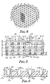
- Fig. 5 is a fragmentary plan view of the back of retroreflecting elements of the invention;
- Fig. 6 represents a view similar to a vertical cross-section along line 6-6 of Fig. 5, but having groove side angles that differ in an exaggerated manner from another groove side angle of the same set; and,
- Fig. 7 is a cross-section along line 7-7 of Fig. 5.
- Fig. 8 is a fragmentary plan view of a canted bisector embodiment of the present invention.
- Fig. 9 represents a schematic view similar to a vertical section along the line 9-9 of Fig. 8.
- A representative retroreflective sheet material 10 manufactured from tooling made by the method of the invention is shown from the back of the sheet material in Fig. 1 and in section in Fig. 2. As shown in Fig. 1, the configured back surface of the sheet material 10 is defined by three
intersecting sets 11, 12, and 13 of parallel V-shaped grooves which form a dense or fully packed array of cube-corner retroreflective elements. The angles for the sides of the grooves, i.e., the groove side angles, are chosen so that the dihedral angles formed at the lines of intersection of the grooves, e.g, thelines retroreflective element 17 in Fig. 1, are approximately 90o. However, at least one of the intersecting sets of parallel grooves includes, in a repeating pattern, grooves having one or both groove side angles different from at least one other groove side angle of the same set. By "repeating pattern," it is meant that a particular distinctive groove side angle(s) occurs periodically across the array of cube-corner retroreflective elements, i.e., is spaced the same number of grooves from its previously occurring position in the array. - Fig. 2 shows part of a representative set of grooves having groove side angles that differ in an exaggerated manner from other groove side angles of the same set. Specifically, Fig. 2 shows a set of
grooves 13 from the sheet material of Fig. 1, i.e., 13₁, 13₂, 13₃, and 13₄. In this set of grooves, there are four different groove side angles "a," "b," "c," and "d," extending between the sides of the grooves and aplane 18 that is perpendicular to a plane defined by thebottom edges 19 of the grooves. The present invention also includes configurations wherein the bottom edges of the grooves are not coplanar. The groove side angles are arranged in an a-b-c-d-a-b-c-d repeating pattern. The groove side angle "a" in this representative set is an angle that would form an orthogonal dihedral angle at the intersection of the groove side with groove sides of the other two sets of grooves (such groove side angles are sometimes termed "orthogonal-producing" herein), and the groove side angles "b," "c," and "d" do not produce orthogonal dihedral angles. The position of the groove sides that would be orthogonal-producing is shown in dotted lines in Fig. 2, and as will be seen, the angle "b" is less than that needed to obtain orthogonality, and the angles "c" and "d" are larger than that needed to obtain orthogonality. - Figs. 3 and 4 show in schematic plan view representative patterns of grooves for a retroreflective article manufactured from tooling made by the method of the invention. In these figures, each line represents one V-shaped groove, with the letter on each side of a line representing the groove side angle on that side of the groove. As illustrated by these examples, each of the three sets of grooves can have a different repeating pattern of groove side angles. In Fig. 3, one set has an a-b-b-a pattern, a second set has an a-b-a-b-b-a-b-a pattern, and the third set has a c-d-e-f-d-c-f-e pattern. In Fig. 4 the different grooving patterns are, respectively, an a-b-b-a pattern, an a-b-a-b-b-a-b-a pattern, and a c-d-d-c pattern.
- Referring to Figs. 5-7, a
retroreflective material 110 of the present invention is shown having reflectingelements 120. Reflectingelements 120 include arectangular base 122, a pair ofrectangular faces base 122. Typically, the rectangular base is less than or equal to 0.5 millimeter long, and the intersection of the rectangular faces 124 and 126 is less than 0.2 millimeter from the base. - The rectangular faces 124 and 126 and the triangular faces 128 and 129 form cube-
corners corners - The reflecting
elements 120 are uniformly arranged in rows, as shown in Fig. 5, with the triangular faces 128 adjacent to the triangular faces 129 of neighboring reflectingelements 120. The rectangular faces 124 and 126 form a first v-shapedgroove 134. The triangular faces 128 and 129 form a second groove 136 having as its approximately perpendicular faces the triangular faces 128 and 129. Thefirst groove 134 and the second groove 136 are perpendicular to each other, as shown in Fig. 5. - As shown in Fig. 7, the
retroreflective elements 120 are formed on the back side of atransparent surface layer 140. Theelements 120 are attached to abacking material 160 which has anadhesive layer 162, which is used to attach theretroreflective material 110 to asigning material 164. - This retroreflector is like that of U.S. Patent No. 4,349,598 (White) (which is incorporated by reference herein), with an important difference. Namely, the dihedral angles of at least some of the cube-corner elements are not 90°, but some angle slightly different from 90°, by a difference of less than 1° usually. The amount of this difference varies so that, for example, one cube-corner element may have a dihedral angle of 90°30′ and the one next to it may have an 89°50′ angle. There is a plurality of such variations in the retroreflector which is said to be multi-nonorthoganal. This feature helps to alleviate variations in the brightness of reflected light across the area of the retroreflector, and it results from variations in the grooves which form the cube-corner elements.
- The groove side angles of the first V-shaped
groove 134 are approximately 45o. The groove side angles of the second groove 136 which has approximately perpendicular sides is approximately 0o. However, at least one of the intersecting sets of parallel grooves includes, preferably in a repeating pattern, grooves having one or both groove side angles different from at least one other groove side angle of the same set. Each retroreflective element of the sheet material of the invention has two cube-corners. In some cases both cube-corners will be identical, whereas in other situations the cube-corners may be slightly different from one another with one or both of the cube-corners being non-orthogonal. - Fig. 6 shows part of a representative set of grooves having groove side angles that differ in an exaggerated manner from other groove side angles of the same set. These grooves will be referred to as right angle channel cross section grooves, since they look approximately like the cross section of a channel having right angle corners or sides perpendicular to the bottom. Specifically, Fig. 6 shows a set of grooves 136 from the sheet material of Fig. 5, i.e. 136₁, 136₂, 136₃, and 136₄. In this set of grooves there are three different groove side angles "g", "h", and "i", extending between the sides of the grooves and a
plane 139 that is perpendicular to a plane defined by thebottom edges 137 of the grooves. The groove side angles are arranged in an g-h-i-g-i-h-g-h repeating pattern. - The groove side angle "g" in this representative set is an angle that would, in this representative article, form an orthogonal dihedral angle at the intersection of the groove side with a groove of the other set of V-shaped grooves. The groove side angles "h", and "i" do not produce orthogonal dihedral angles. The position of the groove sides that would be orthogonal-producing is shown in dotted lines in Fig. 6. The angles "h" and "i" are larger than needed to obtain orthogonality.
- The groove side angles of the set of V-grooves in an article of the present invention can be varied as described above in the discussion about Fig. 2. For example, an orthogonal cube-corner would be formed by the intersection of two groove side angles "a", of Fig. 2, and a groove side angle "g" in Fig. 6.
- Fig. 5 also shows a representative pattern of grooves for a retroreflective article of the invention. In this figure, each horizontal line at the left side of the figure represents one V-shaped groove with the letter on each side of a line representing the groove side angle on that side of the groove. The pairs of vertical lines each represent a second groove having approximately perpendicular sidewalls, with the letter on each side of a line representing the groove side angle on that side of the groove. As illustrated by this example, each of the two sets of grooves can have a different repeating pattern of groove side angles. In Fig. 5, first groove set has a "a-b-b-a" pattern, and the second set has a "g-h-i-g-i-h-g-h" pattern.
- The preferred repeating patterns of grooves form periodically repeating groupings of cube-corner retroreflective elements, or sub-arrays, distributed across one large-area side of the retroreflective article. with the groove pattern shown in Fig. 5, sub-arrays consisting of potentially six distinctive cube-corner retroreflective elements are formed; i.e., assuming a, b, g, h, i are all different from one another, there are six cube-corner retroreflective elements of distinctive shape in the sub-array.
- Instead of being repeated in the repeating patterns discussed above, groove side angles can be repeated more irregularly e.g. 4, 6, and then 5 grooves between recurrences of a given side angle. In most retroreflective articles of the invention, there are a multitude of grooves, and a particular nonorthogonal groove side angle will be repeated numerous times (e.g., 10 or even 100 times or more). Also, in most retroreflective articles of the invention, a large number of the groove side angles (e.g., one-third or more), and often substantially all of the groove side angles, will be nonorthogonal. A particular groove side angle will usually be repeated within a rather short span of grooves, e.g., within a span of 10 or less grooves.
- Since groove side angles may be adjusted or chosen independently from one another, there need not be pairs of elements, but instead, if desired, the elements can all be different from one another. The pairs of elements for the array of Fig. 5 occur because of the particular repeating patterns of grooves used in the array, e.g., by the rotation of the a-b pattern to a b-a pattern in an adjacent groove so that each element is matched by a similarly shaped element rotated 180° from the first element. Whatever repeating patterns are used, so long as the patterns are periodic, the sub-arrays will all be identical to one another.
- It is not essential that all the groove side angles in a sub-array differ from one another. For example, in Fig. 3, c and e could be identical to one another, or other groove side angles could be identical. However, at least one of the two sets of grooves, and for greater control at least two of the sets of grooves (2 of 2 or 2 of 3) include at least one groove side angle that differs from at least one other groove side angle in the same set, with the result that a plurality (i.e., at least two) of the cube-corner retroreflective elements in a sub-array are distinctively shaped, i.e., have a shape different from one another. This difference in shape is more than simply a rotation of an element about its axis, such as the 180° rotation noted above or the similar 180° rotation of the cube-corner elements of U.S. Patent No. 4,588,258, but instead arises, for example, because a particular face of a cube-corner element is not orthogonal-producing.
- A further description of the manner and results of tailoring the groove side angles is found in the parent case, U.S. Patent No. 4,775,219, which is incorporated herein by reference.
- The individual groove side angles in each repeating pattern may be such as to produce orthogonality or non-orthogonality, though as noted, there will be at least one groove side angle in at least one set that is different from another groove side angle in the set, meaning that there must be at least one groove side angle in the set that is not orthogonal-producing. The amount of excess or deficiency from an angle that would be orthogonal-producing is generally a few arc-minutes, i.e., about 15-30 arc-minutes or less, though larger deviations can be used. Preferably, the chosen groove side angles are obtained in the tooling from which articles of the invention are molded to within plus-or-minus about one-half arc-minute, and more preferably, plus-or-minus one-fourth arc-minute. Some further deviation may occur during the molding operation, though preferably there is no more than a two or three arc-minute change, and more preferably, no more than one or two arc-minutes change, during molding. The technique of forming a master for cube-corner retroreflectors by cutting intersecting sets of parallel grooves in a flat metal surface with a V-shaped diamond tool is disclosed in U.S. Patent No. 3,712,706, see for example column 3, lines 35-54, column 4, line 57-column 5, line 24, and
column 17, line 25-column 22, line 47, all of which are incorporated herein by reference. - An advantage of the method of the invention is that when cutting a groove, all of the faces produced along each side of the groove have precisely the same angle. Also, this same face angle can be obtained quite precisely each time that the cutting tool is indexed over to repeat the same groove. This precision in the shaping of identical cube-corner retroreflective elements allows for a precise overlapping of the retroreflective light patterns from each cube-corner retroreflective element and, therefore, minimizes the divergence or discrepancy between cube-corner elements having the same optical design. Such interactive precision contributes to the controlled use of light so that light is directed only at intended angles.
- Preferably, the grooves forming the configured surface of a retroreflective article of the invention extend continuously across a multitude of sub-arrays, with the many individual sub-arrays being created by the repeating pattern of the grooves. Such continuous grooves contrast with the formation of individual pins, each having the shape of an individual cube-corner retroreflective element, such as is used with large cube-corner retroreflective elements, see U.S. Patent No. 3,833,285 (Heenan), and also contrast with the procedure taught in U.S. Patent No. 4,243,618 (Van Arnam) in which an array comprising zones of differently oriented cube-corner retroreflective elements are provided by grooving a planar surface formed by a bundle of pins, then loosening the bundle, rotating the pins, and reasseembling the bundle. The use of continuous grooves is advantageous because they are more convenient and less expensive to cut, and avoid disruption and loss of reflectivity at boundaries between zones.
- The variation from orthogonality in a groove may be obtained by tilting or offsetting a V-shaped tool, such as a diamond-pointed tool, used to form a groove. The same tool may also be used to cut more than one set of grooves. The grooves having nearly perpendicular sides may be cut in a similar fashion.
- Referring to Fig. 9, a schematic cross-section of an alternative embodiment of the present invention is shown. Fig. 8 shows a fragmentary plan view of the embodiment of Fig. 9. In Figs. 8 and 9, a
retroreflective material 170, which permits improved angularity in the horizontal direction, is shown. Such improved angularity is important, for example, in pavement markers, or vertical barrier delineators. Retroreflective material with low angularity will only brightly retroreflect light that impinges on it within a narrow angular range centering approximately on its optical axis. In a pavement marker positioned on a highway, the incident angle is the angle between the line of the light beam of the car headlights and a line perpendicular to the reflective sheeting surface in the pavement marker and the plane of the incident angle is defined by those two lines. Angularity is a property of the sheeting defined as the largest angle away from a line perpendicular to the reflecting surface of the pavement marker at which the marker will remain an effective retroreflector. - In Fig. 9, reflecting
elements Element 172 has a pair oftetragonal faces - The
element 174 has a pair oftetragonal faces base 171 and the bisector 182. Elements such as these will sometimes be referred to as canted bisector elements. - A retroreflective material designed to have improved angularity may include elements, some or all of which are canted bisector elements such as
element 174. The angle, Beta, can, for example, be the same angle for all of the elements, can be varied randomly, can be varied uniformly, or can be designed in a number of repeating or random patterns for the particular end use. - To produce retroreflective material of the present invention which includes canted bisector elements, a master mold is made by cutting a first groove with an approximately 90° included angle tool. The 90° included angle tool is angularly symmetric (45° of the groove on each side of the perpendicular) for some cuts (perpendicular bisector elements) and positioned at varying degrees of asymmetry for others (canted bisector elements).
- The angle, Beta, or the angle from the perpendicular at which the bisector is canted, is typically about 0° to less than about 45° and preferably about 0° to about 35°. The amount of cant of the bisector corresponds to the increase in angularity in the direction of the cant.
- To produce either canted or perpendicular bisector materials, after the mold is cut it then serves as a master mold for the manufacture of negative molds. Duplicates of the master mold can be made from the negative molds by electroforming or other well-known techniques for mold duplication. A transparent plastic film or sheet may then be pressed against the duplicate mold or die to form or emboss in the film or sheet the pattern of the master mold. Alternatively, a liquid film forming material could be cast onto the mold. By controlling the depth of the impression on the plastic film or sheet, the base portion of the film or sheet which does not receive the mold impression then serves as a transparent cover sheet for the resulting retroreflective material.
- In the next step of fabrication, the composite of reflecting elements and transparent cover sheet is preferably backed with a layer of material to strengthen the composite and to protect the reflective elements from dirt and moisture. Typically, the backing layer is an opaque thermoplastic film or sheet, preferably one having good weathering properties. Suitable materials typically have thicknesses about equal to the thickness of the reflecting elements. Other thicknesses are also suitable, depending on the degree of flexibility desired.
- The backing film or sheet may be sealed in a grid pattern or in any other suitable configuration to the reflecting elements. Sealing may be effected by use of a number of methods, including ultrasonic welding, adhesives, or by heat sealing at discrete locations on the array of reflecting elements (see, for example, U.S. Patent No. 3,924,928). Sealing is important to prevent entry of soil and moisture and to preserve the air spaces around the cube-corner reflecting surfaces.
- If desired, the retroreflecting elements may be metalized. If the elements are metalized the air spaces around the elements are not important, as the metal reflects the light. For durability, it is desirable to cover the metal layer with a protective, typically polymeric, layer.
- If added strength or toughness is required in the composite, backing sheets of polycarbonate, polybutyrate or fiber-reinforced plastic may be used. Depending upon the degree of flexibility of the resulting retroreflective material, the material may be rolled or cut into strips or other suitable designs. The retroreflective material may also be backed with an adhesive and release sheet to render it useful for application to any substrate without the added step of applying an adhesive or using other fastening means.
- Groove Side Angle - The angle between the groove side and a plane extending parallel to the length of the groove and perpendicular to a plane defined by the bottom of the sets of grooves. Where the bottoms of the grooves are not co-planar, the plane of reference is the front side of the transparent surface layer or the surface where light enters the retroreflective material.
- Reference Center - A point on or near a retroreflector which is designated to be the center of the device for the purpose of specifying its performance.
- Illumination Axis - A line segment from the reference center to the center of the illumination source.
- Observation Axis - A line segment from the reference center to the center of the light receptor or viewer.
- Observation Angle - The angle between the illumination axis and the observation axis.
- Reference Axis - A designated line segment from the reference center which is used to describe the angular position of the retroreflector, and which for most articles, including sheet material of the invention, is a line perpendicular to the front surface of the article.
- Entrance Angle - The angle between the illumination axis and the reference axis.
- Presentation Angle - The dihedral angle between the entrance plane (formed by the illumination axis and the reference axis) and the observation plane (formed by the illumination axis and the observation axis).
- Datum Mark - A mark on the retroreflector that is used to indicate the orientation of the retroreflector with respect to rotation about the reference axis.
- Observation Half-Plane - The half-plane that originates on the illumination axis and which contains the observation axis.
- First Axis - An axis through the reference center and perpendicular to the observation half-plane.
- Second Axis - An axis through the reference center and perpendicular to both the first axis and the reference axis.
- Rotation Angle - The dihedral angle from the half-plane originating on the reference axis and containing the positive part of the second axis (i.e., the part of the second axis that is in the observation half-plane) to the half-plane originating on the reference axis and containing the datum mark. Note that the rotation angle and presentation angle represent the same motion when the datum mark is aligned vertically with the reference center of the article, the receptor or viewer is aligned vertically with the illumination axis, and the illumination axis is perpendicular to the front surface of the article. Sheeting of the invention having improved rotational symmetry is of advantage since it minimizes the differences in divergence profile caused by mounting the sheeting in different angular orientations.
- Viewing Angle - The angle between the observation axis and the reference axis.
- Divergence Profile - A polar plot of retroreflective intensity as a function of observation angle on the r coordinate and presentation angle on the theta coordinate.
- Observation Profile or Viewing Profile - A polar plot similar to that for the divergence profile but which defines the range of viewing positions contemplated for a viewer with respect to a retroreflective article of the invention. Ideally, the divergence profile for a retroreflective article would match the contemplated observation or viewing profile.
- The term divergence profile is generally used herein when emphasis is on the pattern of light as it leaves the reflector, while the term observation or viewing profile is generally used when emphasis is on the perception of light by a viewer.
Claims (22)
(a) a rectangular base on the back side of the surface layer,
(b) two rectangular faces approximately perpendicular to each other, each one being joined to an edge of the rectangular base to form a reflecting element having a triangular cross section; and
(c) two triangular faces that are approximately parallel to each other and approximately perpendicular to said rectangular faces, and forming the ends of the reflecting elements;
said triangular and said rectangular faces defining a pair of cube-corners therebetween; said reflecting elements being formed by two approximately perpendicular sets of parallel grooves, a first set of V-shaped grooves, and a second set of grooves having a pair of faces nearly perpendicular to said rectangular base, at least one of the sets of grooves including more than one groove having a groove side angle that differs from another groove side angle of the same set by a small amount less than 3°, whereby the array of cube-corner retroreflective elements is characterized by small variations in at least one of the dihedral angles between the faces from one reflecting element to another, said variations existing in at least some but not necessarily all of the reflecting elements.
(a) a rectangular base on the back side of the surface layer;
(b) two mutually substantially perpendicular rectangular faces, each one being joined to an edge of the rectangular base to form a reflecting element having a triangular cross section; and
(c) two substantially parallel triangular faces perpendicular to said rectangular faces;
said triangular and rectangular faces defining a pair of cube-corners therebetween, each pair of said rectangular faces defining an angle of intersection having a bisector which intersects said base, said bisector forming an angle Beta with a line perpendicular to said base, said reflective material including perpendicular bisector elements, wherein Beta is substantially zero, and canted bisector elements wherein Beta is about 0° to less than about 45°.
(a) a rectangular base on the back side of the surface layer;
(b) two approximately mutually perpendicular rectangular faces, each being joined to an edge of the rectangular base to form a reflecting element having a triangular cross section; and
(c) two triangular faces that are approximately parallel to each other and approximately perpendicular to said rectangular faces;
said triangular and rectangular faces defining a pair of cube-corners therebetween; said reflecting elements being formed by two perpendicular sets of parallel grooves, a first set of V-shaped grooves, and a second set of grooves having a pair of faces nearly perpendicular to said rectangular base, at least one of the sets of grooves including more than one groove having a groove side angle that differs from another groove side angle of the same set by a small amount less than 3°, whereby the array of cube-corner retroreflective elements is characterized by small variations in at least one of the dihedral angles between the faces from one reflecting element to another, said variation existing in at least some but not necessarily all of the reflecting elements; each pair of said rectangular faces defining an angle of intersection having a bisector which intersects said base, said bisector forming an angle Beta with a line perpendicular to said base, said reflective material including perpendicular bisector elements, wherein Beta is substantially zero and canted bisector elements wherein Beta is about 0° to less than about 45°.
Applications Claiming Priority (2)
| Application Number | Priority Date | Filing Date | Title |
|---|---|---|---|
| US07/197,107 US4938563A (en) | 1986-11-21 | 1988-05-20 | High efficiency cube corner retroflective material |
| US197107 | 1988-05-20 |
Publications (3)
| Publication Number | Publication Date |
|---|---|
| EP0342958A2 true EP0342958A2 (en) | 1989-11-23 |
| EP0342958A3 EP0342958A3 (en) | 1990-02-21 |
| EP0342958B1 EP0342958B1 (en) | 1994-12-07 |
Family
ID=22728080
Family Applications (1)
| Application Number | Title | Priority Date | Filing Date |
|---|---|---|---|
| EP89304988A Expired - Lifetime EP0342958B1 (en) | 1988-05-20 | 1989-05-17 | High efficiency cube-corner retroreflective material |
Country Status (11)
| Country | Link |
|---|---|
| US (1) | US4938563A (en) |
| EP (1) | EP0342958B1 (en) |
| JP (1) | JP2986161B2 (en) |
| KR (1) | KR0151136B1 (en) |
| CN (1) | CN1022588C (en) |
| AT (1) | ATE115297T1 (en) |
| AU (1) | AU620399B2 (en) |
| BR (1) | BR8902358A (en) |
| CA (1) | CA1319551C (en) |
| DE (1) | DE68919749T2 (en) |
| ZA (1) | ZA893703B (en) |
Cited By (13)
| Publication number | Priority date | Publication date | Assignee | Title |
|---|---|---|---|---|
| WO1995011469A2 (en) * | 1993-10-20 | 1995-04-27 | Minnesota Mining And Manufacturing Company | Directly machined raised structure retroreflective cube corner article and method of manufacture |
| WO1995011471A1 (en) * | 1993-10-20 | 1995-04-27 | Minnesota Mining And Manufacturing Company | Raised zone retroreflective cube corner article and method of manufacture |
| WO1995011463A2 (en) * | 1993-10-20 | 1995-04-27 | Minnesota Mining And Manufacturing Company | Multiple structure cube corner article and method of manufacture |
| WO1997041465A1 (en) * | 1996-04-30 | 1997-11-06 | Minnesota Mining And Manufacturing Company | Glittering cube-corner retroreflective sheeting |
| US5763049A (en) * | 1996-04-30 | 1998-06-09 | Minnesota Mining And Manufacturing Company | Formed ultra-flexible retroreflective cube-corner composite sheeting with target optical properties and method for making same |
| US5770124A (en) * | 1996-04-30 | 1998-06-23 | Minnesota Mining And Manufacturing Company | Method of making glittering cube-corner retroreflective sheeting |
| US5814355A (en) * | 1996-04-30 | 1998-09-29 | Minnesota Mining And Manufacturing Company | Mold for producing glittering cube-corner retroreflective sheeting |
| WO1999015920A1 (en) * | 1997-09-25 | 1999-04-01 | Minnesota Mining And Manufacturing Company | Reflective article incorporating highly nonorthogonal reflecting surfaces |
| WO1999015921A1 (en) * | 1997-09-25 | 1999-04-01 | Minnesota Mining And Manufacturing Company | Dual use reflective article |
| US5948488A (en) * | 1996-04-30 | 1999-09-07 | 3M Innovative Properties Company | Glittering cube-corner article |
| US8596800B2 (en) | 2003-03-06 | 2013-12-03 | 3M Innovative Properties Company | Cube corner retroreflective sheeting having channels |
| US9703023B2 (en) | 2013-03-15 | 2017-07-11 | 3M Innovative Properties Company | Microtiled prismatic cube corner articles |
| DE102021111397A1 (en) | 2021-05-03 | 2022-11-03 | Sick Engineering Gmbh | Reflector for a transmissiometer and transmissiometer equipped therewith |
Families Citing this family (116)
| Publication number | Priority date | Publication date | Assignee | Title |
|---|---|---|---|---|
| US5171624A (en) * | 1990-06-01 | 1992-12-15 | Reflexite Corporation | Retroreflective microprismatic material and method of making same |
| US5138488A (en) * | 1990-09-10 | 1992-08-11 | Minnesota Mining And Manufacturing Company | Retroreflective material with improved angularity |
| US5189553A (en) * | 1992-06-08 | 1993-02-23 | Minnesota Mining And Manufacturing Company | Optimized construction of retroreflective articles for curved applications |
| US5348843A (en) * | 1992-06-12 | 1994-09-20 | Permar Systems, Inc. | Method for making porcelain tags and signs by selectively radiating a frit containing-emulsion coating applied thereto |
| CA2163349A1 (en) * | 1993-06-11 | 1994-12-22 | Terry L. Morris | Laser machined replication tooling |
| US5585164A (en) * | 1993-10-20 | 1996-12-17 | Minnesota Mining And Manufacturing Company | Dual groove set retroreflective cube corner article and method of manufacture |
| EP0724738B1 (en) * | 1993-10-20 | 2000-05-10 | Minnesota Mining And Manufacturing Company | Asymetric cube corner article and method of manufacture |
| US5600484A (en) * | 1993-10-20 | 1997-02-04 | Minnesota Mining And Manufacturing Company | Machining techniques for retroreflective cube corner article and method of manufacture |
| US5759468A (en) | 1993-10-20 | 1998-06-02 | Minnesota Mining And Manufacturing Company | Raised zone retroreflective cube corner article and method of manufacture |
| US5450235A (en) | 1993-10-20 | 1995-09-12 | Minnesota Mining And Manufacturing Company | Flexible cube-corner retroreflective sheeting |
| US5691846A (en) * | 1993-10-20 | 1997-11-25 | Minnesota Mining And Manufacturing Company | Ultra-flexible retroreflective cube corner composite sheetings and methods of manufacture |
| DK0791190T3 (en) * | 1994-11-07 | 2000-03-13 | Minnesota Mining & Mfg | Signaling objects and method of manufacturing the same |
| CN1071359C (en) * | 1994-11-28 | 2001-09-19 | 美国3M公司 | Articles exhibiting durable colour and/or fluorescent properties |
| US5816238A (en) * | 1994-11-28 | 1998-10-06 | Minnesota Mining And Manufacturing Company | Durable fluorescent solar collectors |
| US5485311A (en) * | 1995-01-06 | 1996-01-16 | Mcallister; Richard | Method of increasing retroreflective brightness in a retroreflective sheet material |
| US5706133A (en) * | 1995-02-09 | 1998-01-06 | Minnesota Mining And Manufacturing Company | Retroreflective signage articles, kits for producing same, and methods of making signage articles |
| US6190757B1 (en) * | 1995-02-09 | 2001-02-20 | 3M Innovative Properties Company | Compositions and thermal mass transfer donor elements for use in producing signage articles |
| EP0809679B1 (en) * | 1995-02-16 | 2000-05-17 | Minnesota Mining And Manufacturing Company | Articles incorporating pressure-sensitive adhesives having improved adhesion to plasticized polyvinyl chloride |
| US5700077A (en) * | 1995-03-23 | 1997-12-23 | Minnesota Mining And Manufacturing Company | Line light source including fluorescent colorant |
| WO1996042024A1 (en) * | 1995-06-09 | 1996-12-27 | Minnesota Mining And Manufacturing Company | Retroreflective cube corner article having scalene base triangles |
| US5639530A (en) * | 1995-06-16 | 1997-06-17 | Minnesota Mining And Manufacturing Company | Retroreflective articles comprising a non-thermoplastic hydrocarbon elastomer adhesive layer for life saving devices at sea |
| US20030170426A1 (en) * | 1995-12-01 | 2003-09-11 | W. Scott Thielman | Cellular retroreflective sheeting |
| US5870643A (en) * | 1995-12-28 | 1999-02-09 | Eastman Kodak Company | Single-use flash cameras with reflector or siren |
| US5706132A (en) * | 1996-01-19 | 1998-01-06 | Minnesota Mining And Manufacturing Company | Dual orientation retroreflective sheeting |
| USD383312S (en) * | 1996-01-19 | 1997-09-09 | Minnesota Mining And Manufacturing Company | Seal pattern on retroreflective sheeting |
| US5905826A (en) * | 1996-01-24 | 1999-05-18 | Minnesota Mining And Manufacturing Co. | Conspicuity marking system including light guide and retroreflective structure |
| CA2169807C (en) | 1996-02-19 | 1999-09-07 | Italo Caroli | Reflex pin with adjusted angle |
| US5805338A (en) * | 1996-04-10 | 1998-09-08 | Minnesota Minning And Manufacturing Company | Pillowed flexible cube-corner sheeting and methods of manufacture |
| US5919551A (en) * | 1996-04-12 | 1999-07-06 | 3M Innovative Properties Company | Variable pitch structured optical film |
| US6015214A (en) * | 1996-05-30 | 2000-01-18 | Stimsonite Corporation | Retroreflective articles having microcubes, and tools and methods for forming microcubes |
| JP3974959B2 (en) * | 1996-09-30 | 2007-09-12 | スリーエム カンパニー | Method for manufacturing retroreflective information display sheet |
| US5734501A (en) * | 1996-11-01 | 1998-03-31 | Minnesota Mining And Manufacturing Company | Highly canted retroreflective cube corner article |
| US6021559A (en) * | 1996-11-01 | 2000-02-08 | 3M Innovative Properties Company | Methods of making a cube corner article master mold |
| JPH10143098A (en) * | 1996-11-08 | 1998-05-29 | Minnesota Mining & Mfg Co <3M> | Retroreflecting sheet capabile of emitting light by itself, and reflective indicator |
| US6861141B2 (en) * | 1996-12-04 | 2005-03-01 | Gina M. Buccellato | Pavement marking article and raised pavement marker that uses pressure sensitive adhesive |
| US5981113A (en) | 1996-12-17 | 1999-11-09 | 3M Innovative Properties Company | Curable ink composition and imaged retroreflective article therefrom |
| US6461003B1 (en) | 1997-06-12 | 2002-10-08 | Purdue Research Foundation | Corner cube arrays and manufacture thereof |
| US5889615A (en) * | 1997-06-27 | 1999-03-30 | Minnesota Mining And Manufacturing Company | Dual axis retroreflective articles |
| US6253442B1 (en) * | 1997-07-02 | 2001-07-03 | 3M Innovative Properties Company | Retroreflective cube corner sheeting mold and method for making the same |
| US5981032A (en) * | 1997-07-02 | 1999-11-09 | 3M Innovative Properties Company | Retroreflective cube corner sheeting mold and sheeting formed therefrom |
| US6036322A (en) * | 1997-12-01 | 2000-03-14 | Reflexite Corporation | Multi-orientation retroreflective structure |
| US6045230A (en) * | 1998-02-05 | 2000-04-04 | 3M Innovative Properties Company | Modulating retroreflective article |
| US6282026B1 (en) | 1998-02-05 | 2001-08-28 | 3M Innovative Properties Company | Retroreflectors having two optical surfaces and varying retroreflectivity |
| US6067143A (en) * | 1998-06-04 | 2000-05-23 | Tomita; Akira | High contrast micro display with off-axis illumination |
| US6322652B1 (en) * | 1998-09-04 | 2001-11-27 | 3M Innovative Properties Company | Method of making a patterned surface articles |
| US6050691A (en) * | 1998-10-19 | 2000-04-18 | 3M Innovative Properties Company | Method of making randomly oriented cube-corner articles |
| US6055108A (en) * | 1999-02-11 | 2000-04-25 | Minnesota Mining And Manufacturing Company | Imaging articles and methods using dual-axis retroreflective elements |
| US6172810B1 (en) | 1999-02-26 | 2001-01-09 | 3M Innovative Properties Company | Retroreflective articles having polymer multilayer reflective coatings |
| US6482510B1 (en) | 1999-03-30 | 2002-11-19 | 3M Innovative Properties Company | Digital printable and releasable form construction and composition useful thereto |
| US6406787B1 (en) | 1999-03-30 | 2002-06-18 | 3M Innovative Properties Company | Digital printable and releasable form construction and composition useful thereto |
| US6540367B1 (en) | 1999-04-07 | 2003-04-01 | 3M Innovative Properties Company | Structured surface articles containing geometric structures with compound faces and methods for making same |
| US6246428B1 (en) | 1999-05-11 | 2001-06-12 | 3M Innovoative Properties Company | Method and system for thermal mass transfer printing |
| KR20010018578A (en) * | 1999-08-20 | 2001-03-05 | 성재갑 | Transformed Cube Corner Retroreflector Frustrated-Total-Internal-Reflecting Incident Rays and Method of Processing thereof |
| KR100373209B1 (en) | 1999-09-11 | 2003-02-25 | 주식회사 엘지화학 | Retroreflective article |
| US8728610B2 (en) * | 2000-02-25 | 2014-05-20 | 3M Innovative Properties Company | Compound mold and structured surface articles containing geometric structures with compound faces and method of making same |
| US6741523B1 (en) | 2000-05-15 | 2004-05-25 | 3M Innovative Properties Company | Microstructured time dependent indicators |
| US6572977B1 (en) | 2000-09-12 | 2003-06-03 | 3M Innovative Properties Company | Fluorescent red composition and articles made therefrom |
| US6312132B1 (en) | 2000-09-12 | 2001-11-06 | 3M Innovative Properties Company | Fluorescent red article and retroreflective article made therefrom |
| DE60236297D1 (en) * | 2001-06-11 | 2010-06-17 | Avery Dennison Corp | REPLACEMENTS WITH CONTROLLED DIVERGENCE MANUFACTURED BY THE GROOVING METHOD |
| KR100490816B1 (en) * | 2001-06-15 | 2005-05-24 | 샤프 가부시키가이샤 | Micro corner cube array, method of making the micro corner cube array and reflective type display device |
| US6931665B2 (en) | 2001-07-30 | 2005-08-23 | 3M Innovative Properties Company | Vapor permeable retroreflective garment |
| KR100417570B1 (en) * | 2001-08-17 | 2004-02-05 | 손광현 | Reflex reflector having double hologram diffraction grating layers |
| US20030211299A1 (en) * | 2001-09-27 | 2003-11-13 | 3M Innovative Properties Company | Adhesion-enhancing surfaces for marking materials |
| ATE434781T1 (en) * | 2002-04-03 | 2009-07-15 | 3M Innovative Properties Co | PRODUCTS FOR DISPLAYING TIME OR TIME-TEMPERATURE |
| JP2003315516A (en) * | 2002-04-18 | 2003-11-06 | Three M Innovative Properties Co | Reflective multilayer body |
| TWI341927B (en) * | 2002-05-15 | 2011-05-11 | Reflexite Corp | Optical structures |
| JP2005530160A (en) * | 2002-06-14 | 2005-10-06 | スリーエム イノベイティブ プロパティズ カンパニー | Shock indicator |
| DE10234246A1 (en) * | 2002-07-27 | 2004-02-05 | Tesa Ag | Pressure-sensitive adhesive material for bonding transparent substrates, e.g. in liquid crystal displays and other optical applications, comprises block copolymers with blocks of different refractive index |
| JP4079731B2 (en) * | 2002-09-24 | 2008-04-23 | 日東電工株式会社 | Light scattering reflector, method for producing the same, and reflective liquid crystal display device |
| US6976770B2 (en) * | 2002-10-14 | 2005-12-20 | Guide Corporation | Hermetically sealed lamp housing and method of making |
| US6871966B2 (en) * | 2002-12-12 | 2005-03-29 | Avery Dennison Corporation | Retroreflector with controlled divergence made by the method of localized substrate stress |
| US7156527B2 (en) | 2003-03-06 | 2007-01-02 | 3M Innovative Properties Company | Lamina comprising cube corner elements and retroreflective sheeting |
| DE10312708B4 (en) * | 2003-03-21 | 2007-06-28 | Ovd Kinegram Ag | retroreflector |
| US7396579B2 (en) * | 2003-05-15 | 2008-07-08 | 3M Innovative Properties Company | Fluorescent red-orange retroreflective sheeting |
| JP4457229B2 (en) | 2003-11-10 | 2010-04-28 | エイジェンシー フォー サイエンス, テクノロジー アンド リサーチ | Manufacture of microneedles and microneedles |
| EP1698915B1 (en) * | 2003-12-02 | 2014-11-12 | Nippon Carbide Kogyo Kabushiki Kaisha | Triangular pyramid type cube corner retro-reflection article having curved reflection side surface |
| WO2005066665A1 (en) * | 2003-12-24 | 2005-07-21 | Avery Dennison Corporation | Cube corner retroreflector with limited range |
| US7195360B2 (en) * | 2004-12-28 | 2007-03-27 | 3M Innovative Properties Company | Prismatic retroreflective article and method |
| KR20130008643A (en) * | 2004-12-28 | 2013-01-22 | 쓰리엠 이노베이티브 프로퍼티즈 컴파니 | Prismatic retroreflective article with fluorine- or silicon-containing prisms |
| JP4890800B2 (en) * | 2005-06-29 | 2012-03-07 | スリーエム イノベイティブ プロパティズ カンパニー | Transparent wavelength selective retroreflector |
| US7815355B2 (en) * | 2005-08-27 | 2010-10-19 | 3M Innovative Properties Company | Direct-lit backlight having light recycling cavity with concave transflector |
| TWI464494B (en) * | 2005-08-27 | 2014-12-11 | 3M Innovative Properties Co | Illumination assembly and system |
| US20070047228A1 (en) * | 2005-08-27 | 2007-03-01 | 3M Innovative Properties Company | Methods of forming direct-lit backlights having light recycling cavity with concave transflector |
| US7537374B2 (en) * | 2005-08-27 | 2009-05-26 | 3M Innovative Properties Company | Edge-lit backlight having light recycling cavity with concave transflector |
| EP1932031B1 (en) * | 2005-09-26 | 2012-06-20 | Avery Dennison Corporation | Retroreflective sheeting comprising a divergence enhancing layer |
| US7637639B2 (en) * | 2005-12-21 | 2009-12-29 | 3M Innovative Properties Company | LED emitter with radial prismatic light diverter |
| EP3270195B1 (en) | 2006-04-18 | 2023-12-20 | 3M Innovative Properties Company | Microstructured articles comprising nitrogen containing ingredient |
| US7611251B2 (en) | 2006-04-18 | 2009-11-03 | 3M Innovative Properties Company | Retroreflective articles comprising olefinic seal films |
| KR101469292B1 (en) * | 2006-07-17 | 2014-12-04 | 애브리 데니슨 코포레이션 | Method of making an array of aberrated optical elements |
| DE102006035786A1 (en) * | 2006-07-28 | 2008-03-13 | Tesa Ag | Adhesive film with high optical transparency for bonding as splinter protection on glass panes in consumer electronic components |
| US20080145626A1 (en) * | 2006-12-15 | 2008-06-19 | 3M Innovative Properties Company | Bossed laser validation form |
| US20080251417A1 (en) * | 2007-04-16 | 2008-10-16 | David Goodson | Using lenses and lens arrays to enhance the appearance of objects |
| US7547105B2 (en) * | 2007-07-16 | 2009-06-16 | 3M Innovative Properties Company | Prismatic retroreflective article with cross-linked image layer and method of making same |
| JP4858650B2 (en) * | 2010-03-02 | 2012-01-18 | ソニー株式会社 | Optical body, window material, joinery and solar shading device |
| USD665584S1 (en) * | 2010-03-05 | 2012-08-21 | Orafol Europe Gmbh | Retro-reflective sheeting with a corner cube surface pattern having angular corner cube circular regions |
| DE202010007107U1 (en) * | 2010-05-21 | 2011-11-09 | Sick Ag | widening reflector |
| CN102918430B (en) | 2010-06-01 | 2016-08-24 | 3M创新有限公司 | Multi-layer sealed film |
| WO2012082391A1 (en) | 2010-12-14 | 2012-06-21 | 3M Innovative Properties Company | Images and method of making the same |
| US9366790B2 (en) | 2011-05-31 | 2016-06-14 | 3M Innovative Properties Company | Retroreflective articles having composite cube-corners and methods of making |
| US9415539B2 (en) | 2011-05-31 | 2016-08-16 | 3M Innovative Properties Company | Method for making microstructured tools having discontinuous topographies, and articles produced therefrom |
| EP2714358B1 (en) | 2011-05-31 | 2020-02-19 | 3M Innovative Properties Company | Methods for making differentially pattern cured microstructured articles |
| JP2015507756A (en) | 2011-11-30 | 2015-03-12 | リアルディー インコーポレイテッド | Laser beam scanning display apparatus and method |
| SG11201406273XA (en) | 2012-04-06 | 2014-11-27 | 3M Innovative Properties Co | Tools for making retroreflective articles |
| CN102736150B (en) * | 2012-06-21 | 2014-09-17 | 绵阳龙华薄膜有限公司 | Improved microprism retroreflection material |
| WO2015187433A1 (en) * | 2014-05-27 | 2015-12-10 | Wang Michael W | Methods for optimizing retro-reflective display systems |
| JP2016080937A (en) * | 2014-10-20 | 2016-05-16 | 株式会社アスカネット | Mold for forming retroreflector and method of manufacturing retroreflector using the same |
| WO2017007615A1 (en) | 2015-07-07 | 2017-01-12 | 3M Innovative Properties Company | Polyurethane layer for a light directing article |
| CN108139516B (en) * | 2015-09-25 | 2020-10-16 | 亚斯卡奈特股份有限公司 | Retroreflective article |
| DE102016001543A1 (en) | 2016-02-10 | 2017-08-10 | Optoflux GmbH | Retro-reflectors |
| WO2017156448A1 (en) * | 2016-03-11 | 2017-09-14 | Mirraviz, Inc. | Customized reflection profiles for retro-reflective display system optimization |
| KR102437478B1 (en) | 2016-06-07 | 2022-08-30 | 쓰리엠 이노베이티브 프로퍼티즈 캄파니 | Acrylic Polyvinyl Acetal Film for Light Directing Applications |
| WO2018139035A1 (en) * | 2017-01-27 | 2018-08-02 | 株式会社アスカネット | Retroflector and retroflector production method |
| US10444615B2 (en) * | 2017-08-29 | 2019-10-15 | Avery Dennison Corporation | Retroreflective sheeting for projector-based display system |
| US11675086B1 (en) | 2019-08-20 | 2023-06-13 | Scan Systems, Corp. | Time-of-flight-based apparatus, systems, and methods for measuring tubular goods |
| US10794021B1 (en) * | 2020-06-03 | 2020-10-06 | Mark Joseph O'Neill | Retroreflective traffic stripe |
| CN115835943A (en) | 2020-08-27 | 2023-03-21 | 奥拉光学系统有限合伙公司 | Microprismatic retroreflective molds, sheeting, and articles and methods of making the same |
Citations (10)
| Publication number | Priority date | Publication date | Assignee | Title |
|---|---|---|---|---|
| US3712706A (en) | 1971-01-04 | 1973-01-23 | American Cyanamid Co | Retroreflective surface |
| US3817596A (en) | 1971-07-07 | 1974-06-18 | Ichikoh Industries Ltd | Light reflector and method of diffusing the reflecting light of a light reflector |
| US3833285A (en) | 1973-05-22 | 1974-09-03 | Amerace Esna Corp | Retrodirective reflector visible over wide range of observation angles |
| US3924928A (en) | 1975-03-12 | 1975-12-09 | Robert C Trimble | Attachment for reflectors for spoke wheels |
| US3924929A (en) | 1966-11-14 | 1975-12-09 | Minnesota Mining & Mfg | Retro-reflective sheet material |
| US4243618A (en) | 1978-10-23 | 1981-01-06 | Avery International Corporation | Method for forming retroreflective sheeting |
| US4349598A (en) | 1976-12-01 | 1982-09-14 | Minnesota Mining And Manufacturing Company | High incidence angle retroreflective material |
| US4588258A (en) | 1983-09-12 | 1986-05-13 | Minnesota Mining And Manufacturing Company | Cube-corner retroreflective articles having wide angularity in multiple viewing planes |
| US4672089A (en) | 1984-08-10 | 1987-06-09 | Amerace Corporation | Retroreflective sheeting |
| US4775219A (en) | 1986-11-21 | 1988-10-04 | Minnesota Mining & Manufacturing Company | Cube-corner retroreflective articles having tailored divergence profiles |
Family Cites Families (12)
| Publication number | Priority date | Publication date | Assignee | Title |
|---|---|---|---|---|
| US29396A (en) * | 1860-07-31 | Apparatus eob cleaning windows | ||
| US4208090A (en) * | 1967-03-24 | 1980-06-17 | Amerace Corporation | Reflector structure |
| US3923378A (en) * | 1973-04-24 | 1975-12-02 | Amerace Corp | Cube-corner reflector with non-aligned cube axes and element axes |
| US4073568A (en) * | 1975-11-26 | 1978-02-14 | Ferro Corporation | Retroreflector units with three mutually perpendicular surfaces defining a trihedral angle of a rectangular parallelepiped |
| US4066236A (en) * | 1976-06-25 | 1978-01-03 | Beatrice Foods Co. | Cube corner type retroreflector bodies and molds made therewith |
| US4095773A (en) * | 1976-11-18 | 1978-06-20 | Beatrice Foods Co. | Subassemblies for cube corner type retroreflector molds |
| US4202600A (en) * | 1978-04-24 | 1980-05-13 | Avery International Corporation | Diced retroreflective sheeting |
| US4576850A (en) * | 1978-07-20 | 1986-03-18 | Minnesota Mining And Manufacturing Company | Shaped plastic articles having replicated microstructure surfaces |
| US4582885A (en) * | 1978-07-20 | 1986-04-15 | Minnesota Mining And Manufacturing Company | Shaped plastic articles having replicated microstructure surfaces |
| US4189209A (en) * | 1978-10-13 | 1980-02-19 | Ferro Corporation | Retroreflector of integrated light reflecting units of varying configurations |
| US4460449A (en) * | 1983-01-03 | 1984-07-17 | Amerace Corporation | Apparatus for making a tool |
| US4703999A (en) * | 1986-06-16 | 1987-11-03 | Minnesota Mining And Manufacturing Company | Wide-angle-reflective cube-corner retroreflective sheeting |
-
1988
- 1988-05-20 US US07/197,107 patent/US4938563A/en not_active Expired - Lifetime
-
1989
- 1989-05-17 EP EP89304988A patent/EP0342958B1/en not_active Expired - Lifetime
- 1989-05-17 AU AU34879/89A patent/AU620399B2/en not_active Ceased
- 1989-05-17 AT AT89304988T patent/ATE115297T1/en not_active IP Right Cessation
- 1989-05-17 ZA ZA893703A patent/ZA893703B/en unknown
- 1989-05-17 DE DE68919749T patent/DE68919749T2/en not_active Expired - Fee Related
- 1989-05-19 JP JP1126553A patent/JP2986161B2/en not_active Expired - Fee Related
- 1989-05-19 BR BR898902358A patent/BR8902358A/en not_active IP Right Cessation
- 1989-05-19 CA CA000600167A patent/CA1319551C/en not_active Expired - Fee Related
- 1989-05-19 KR KR1019890006725A patent/KR0151136B1/en not_active IP Right Cessation
- 1989-05-19 CN CN89104605A patent/CN1022588C/en not_active Expired - Fee Related
Patent Citations (10)
| Publication number | Priority date | Publication date | Assignee | Title |
|---|---|---|---|---|
| US3924929A (en) | 1966-11-14 | 1975-12-09 | Minnesota Mining & Mfg | Retro-reflective sheet material |
| US3712706A (en) | 1971-01-04 | 1973-01-23 | American Cyanamid Co | Retroreflective surface |
| US3817596A (en) | 1971-07-07 | 1974-06-18 | Ichikoh Industries Ltd | Light reflector and method of diffusing the reflecting light of a light reflector |
| US3833285A (en) | 1973-05-22 | 1974-09-03 | Amerace Esna Corp | Retrodirective reflector visible over wide range of observation angles |
| US3924928A (en) | 1975-03-12 | 1975-12-09 | Robert C Trimble | Attachment for reflectors for spoke wheels |
| US4349598A (en) | 1976-12-01 | 1982-09-14 | Minnesota Mining And Manufacturing Company | High incidence angle retroreflective material |
| US4243618A (en) | 1978-10-23 | 1981-01-06 | Avery International Corporation | Method for forming retroreflective sheeting |
| US4588258A (en) | 1983-09-12 | 1986-05-13 | Minnesota Mining And Manufacturing Company | Cube-corner retroreflective articles having wide angularity in multiple viewing planes |
| US4672089A (en) | 1984-08-10 | 1987-06-09 | Amerace Corporation | Retroreflective sheeting |
| US4775219A (en) | 1986-11-21 | 1988-10-04 | Minnesota Mining & Manufacturing Company | Cube-corner retroreflective articles having tailored divergence profiles |
Non-Patent Citations (3)
| Title |
|---|
| H. D. ECKHARDT: "Simple Model of Corner Reflector Phenomena", APPLIED OPTICS, vol. 10, no. 7, July 1971 (1971-07-01) |
| N.E. RITYN: "Optics of Corner Cube Reflectors", SOVIET JOURNAL OF OPTICAL TECHNOLOGY, vol. 34, pages 198 |
| P. R. YODER: "Study of Light Deviation Errors in Triple Mirrors and Tetrahedral Prisms", JOURNAL OF THE OPTICAL SOCIETY OF AMERICA, vol. 48, no. 7, July 1958 (1958-07-01) |
Cited By (28)
| Publication number | Priority date | Publication date | Assignee | Title |
|---|---|---|---|---|
| CN1040691C (en) * | 1993-10-20 | 1998-11-11 | 美国3M公司 | Directly machined raised structure retroreflective cube corner article and method of mfg. |
| CN1040693C (en) * | 1993-10-20 | 1998-11-11 | 美国3M公司 | Raised zone retroreflective cube corner article and method of manufacture |
| US5914813A (en) * | 1993-10-20 | 1999-06-22 | 3M Innovative Properties Company | Multiple structure cube corner article |
| WO1995011463A3 (en) * | 1993-10-20 | 1995-08-24 | Minnesota Mining & Mfg | Multiple structure cube corner article and method of manufacture |
| WO1995011469A3 (en) * | 1993-10-20 | 1995-09-08 | Minnesota Mining & Mfg | Directly machined raised structure retroreflective cube corner article and method of manufacture |
| US5557836A (en) * | 1993-10-20 | 1996-09-24 | Minnesota Mining And Manufacturing Company | Method of manufacturing a cube corner article |
| WO1995011469A2 (en) * | 1993-10-20 | 1995-04-27 | Minnesota Mining And Manufacturing Company | Directly machined raised structure retroreflective cube corner article and method of manufacture |
| US5721640A (en) * | 1993-10-20 | 1998-02-24 | Minnesota Mining And Manufacturing Company | Multiple structure cube corner article and method of manufacture |
| WO1995011463A2 (en) * | 1993-10-20 | 1995-04-27 | Minnesota Mining And Manufacturing Company | Multiple structure cube corner article and method of manufacture |
| WO1995011471A1 (en) * | 1993-10-20 | 1995-04-27 | Minnesota Mining And Manufacturing Company | Raised zone retroreflective cube corner article and method of manufacture |
| AU719746B2 (en) * | 1996-04-30 | 2000-05-18 | Minnesota Mining And Manufacturing Company | Glittering cube-corner retroreflective sheeting |
| US5814355A (en) * | 1996-04-30 | 1998-09-29 | Minnesota Mining And Manufacturing Company | Mold for producing glittering cube-corner retroreflective sheeting |
| KR100294097B1 (en) * | 1996-04-30 | 2001-09-07 | 스프레이그 로버트 월터 | Glittering Cube-Corner Retroreflective Sheeting |
| US5840405A (en) * | 1996-04-30 | 1998-11-24 | Minnesota Mining And Manufacturing Company | Glittering cube-corner retroreflective sheeting |
| WO1997041465A1 (en) * | 1996-04-30 | 1997-11-06 | Minnesota Mining And Manufacturing Company | Glittering cube-corner retroreflective sheeting |
| KR100294100B1 (en) * | 1996-04-30 | 2001-09-07 | 스프레이그 로버트 월터 | Method of Making Glittering Cube-Corner Retroreflective Sheeting |
| US5763049A (en) * | 1996-04-30 | 1998-06-09 | Minnesota Mining And Manufacturing Company | Formed ultra-flexible retroreflective cube-corner composite sheeting with target optical properties and method for making same |
| US5948488A (en) * | 1996-04-30 | 1999-09-07 | 3M Innovative Properties Company | Glittering cube-corner article |
| US5770124A (en) * | 1996-04-30 | 1998-06-23 | Minnesota Mining And Manufacturing Company | Method of making glittering cube-corner retroreflective sheeting |
| WO1999015920A1 (en) * | 1997-09-25 | 1999-04-01 | Minnesota Mining And Manufacturing Company | Reflective article incorporating highly nonorthogonal reflecting surfaces |
| WO1999015921A1 (en) * | 1997-09-25 | 1999-04-01 | Minnesota Mining And Manufacturing Company | Dual use reflective article |
| US8596800B2 (en) | 2003-03-06 | 2013-12-03 | 3M Innovative Properties Company | Cube corner retroreflective sheeting having channels |
| US9465147B2 (en) | 2003-03-06 | 2016-10-11 | 3M Innovative Properties Company | Cube corner retroreflective sheeting having channels |
| US9724882B2 (en) | 2003-03-06 | 2017-08-08 | 3M Innovative Properties Company | Cube corner retroreflective sheeting having channels |
| US10562249B2 (en) | 2003-03-06 | 2020-02-18 | 3M Innovative Properties Company | Cube corner retroreflective sheeting having channels |
| US9703023B2 (en) | 2013-03-15 | 2017-07-11 | 3M Innovative Properties Company | Microtiled prismatic cube corner articles |
| US10502875B2 (en) | 2013-03-15 | 2019-12-10 | 3M Innovative Properties Company | Microtiled prismatic cube corner articles |
| DE102021111397A1 (en) | 2021-05-03 | 2022-11-03 | Sick Engineering Gmbh | Reflector for a transmissiometer and transmissiometer equipped therewith |
Also Published As
| Publication number | Publication date |
|---|---|
| AU620399B2 (en) | 1992-02-20 |
| US4938563A (en) | 1990-07-03 |
| AU3487989A (en) | 1989-11-23 |
| CN1022588C (en) | 1993-10-27 |
| EP0342958A3 (en) | 1990-02-21 |
| DE68919749D1 (en) | 1995-01-19 |
| ATE115297T1 (en) | 1994-12-15 |
| DE68919749T2 (en) | 1995-06-14 |
| JPH0222602A (en) | 1990-01-25 |
| BR8902358A (en) | 1990-01-09 |
| ZA893703B (en) | 1991-01-30 |
| KR890017553A (en) | 1989-12-16 |
| KR0151136B1 (en) | 1998-12-15 |
| JP2986161B2 (en) | 1999-12-06 |
| EP0342958B1 (en) | 1994-12-07 |
| CN1038885A (en) | 1990-01-17 |
| CA1319551C (en) | 1993-06-29 |
Similar Documents
| Publication | Publication Date | Title |
|---|---|---|
| EP0342958B1 (en) | High efficiency cube-corner retroreflective material | |
| US4775219A (en) | Cube-corner retroreflective articles having tailored divergence profiles | |
| JP3590061B2 (en) | Retroreflective corner cube article and method of making the same | |
| EP0548280B1 (en) | Retroreflective material with improved angularity | |
| EP0356005B1 (en) | High efficiency retroreflective material | |
| US7188960B2 (en) | Retroreflective sheeting having high retroreflectance at low observation angles | |
| US4588258A (en) | Cube-corner retroreflective articles having wide angularity in multiple viewing planes | |
| US6136416A (en) | Raised zone retroreflective cube corner article | |
| US5898523A (en) | Tiled retroreflective sheeting composed of highly canted cube corner elements | |
| US7156527B2 (en) | Lamina comprising cube corner elements and retroreflective sheeting | |
| EP0137736B1 (en) | Cube-corner retroreflective articles having wide angularity in multiple viewing planes | |
| JP3834596B2 (en) | Asymmetric corner cube article and manufacturing method | |
| US4243618A (en) | Method for forming retroreflective sheeting | |
| US5585164A (en) | Dual groove set retroreflective cube corner article and method of manufacture |
Legal Events
| Date | Code | Title | Description |
|---|---|---|---|
| PUAI | Public reference made under article 153(3) epc to a published international application that has entered the european phase |
Free format text: ORIGINAL CODE: 0009012 |
|
| AK | Designated contracting states |
Kind code of ref document: A2 Designated state(s): AT DE FR GB IT NL SE |
|
| PUAL | Search report despatched |
Free format text: ORIGINAL CODE: 0009013 |
|
| AK | Designated contracting states |
Kind code of ref document: A3 Designated state(s): AT DE FR GB IT NL SE |
|
| 17P | Request for examination filed |
Effective date: 19900809 |
|
| 17Q | First examination report despatched |
Effective date: 19921012 |
|
| GRAA | (expected) grant |
Free format text: ORIGINAL CODE: 0009210 |
|
| ITF | It: translation for a ep patent filed |
Owner name: BARZANO' E ZANARDO ROMA S.P.A. |
|
| AK | Designated contracting states |
Kind code of ref document: B1 Designated state(s): AT DE FR GB IT NL SE |
|
| REF | Corresponds to: |
Ref document number: 115297 Country of ref document: AT Date of ref document: 19941215 Kind code of ref document: T |
|
| REF | Corresponds to: |
Ref document number: 68919749 Country of ref document: DE Date of ref document: 19950119 |
|
| EAL | Se: european patent in force in sweden |
Ref document number: 89304988.2 |
|
| ET | Fr: translation filed | ||
| PLBE | No opposition filed within time limit |
Free format text: ORIGINAL CODE: 0009261 |
|
| STAA | Information on the status of an ep patent application or granted ep patent |
Free format text: STATUS: NO OPPOSITION FILED WITHIN TIME LIMIT |
|
| 26N | No opposition filed | ||
| PGFP | Annual fee paid to national office [announced via postgrant information from national office to epo] |
Ref country code: SE Payment date: 19980420 Year of fee payment: 10 |
|
| PG25 | Lapsed in a contracting state [announced via postgrant information from national office to epo] |
Ref country code: SE Free format text: LAPSE BECAUSE OF NON-PAYMENT OF DUE FEES Effective date: 19990518 |
|
| EUG | Se: european patent has lapsed |
Ref document number: 89304988.2 |
|
| PGFP | Annual fee paid to national office [announced via postgrant information from national office to epo] |
Ref country code: AT Payment date: 20000504 Year of fee payment: 12 |
|
| PG25 | Lapsed in a contracting state [announced via postgrant information from national office to epo] |
Ref country code: AT Free format text: LAPSE BECAUSE OF NON-PAYMENT OF DUE FEES Effective date: 20010517 |
|
| REG | Reference to a national code |
Ref country code: GB Ref legal event code: IF02 |
|
| PGFP | Annual fee paid to national office [announced via postgrant information from national office to epo] |
Ref country code: NL Payment date: 20020507 Year of fee payment: 14 |
|
| PG25 | Lapsed in a contracting state [announced via postgrant information from national office to epo] |
Ref country code: NL Free format text: LAPSE BECAUSE OF NON-PAYMENT OF DUE FEES Effective date: 20031201 |
|
| NLV4 | Nl: lapsed or anulled due to non-payment of the annual fee |
Effective date: 20031201 |
|
| PG25 | Lapsed in a contracting state [announced via postgrant information from national office to epo] |
Ref country code: IT Free format text: LAPSE BECAUSE OF NON-PAYMENT OF DUE FEES;WARNING: LAPSES OF ITALIAN PATENTS WITH EFFECTIVE DATE BEFORE 2007 MAY HAVE OCCURRED AT ANY TIME BEFORE 2007. THE CORRECT EFFECTIVE DATE MAY BE DIFFERENT FROM THE ONE RECORDED. Effective date: 20050517 |
|
| PGFP | Annual fee paid to national office [announced via postgrant information from national office to epo] |
Ref country code: FR Payment date: 20060517 Year of fee payment: 18 |
|
| PGFP | Annual fee paid to national office [announced via postgrant information from national office to epo] |
Ref country code: DE Payment date: 20060630 Year of fee payment: 18 |
|
| REG | Reference to a national code |
Ref country code: FR Ref legal event code: ST Effective date: 20080131 |
|
| PG25 | Lapsed in a contracting state [announced via postgrant information from national office to epo] |
Ref country code: DE Free format text: LAPSE BECAUSE OF NON-PAYMENT OF DUE FEES Effective date: 20071201 |
|
| PG25 | Lapsed in a contracting state [announced via postgrant information from national office to epo] |
Ref country code: FR Free format text: LAPSE BECAUSE OF NON-PAYMENT OF DUE FEES Effective date: 20070531 |
|
| PGFP | Annual fee paid to national office [announced via postgrant information from national office to epo] |
Ref country code: GB Payment date: 20080529 Year of fee payment: 20 |
|
| REG | Reference to a national code |
Ref country code: GB Ref legal event code: PE20 Expiry date: 20090516 |
|
| PG25 | Lapsed in a contracting state [announced via postgrant information from national office to epo] |
Ref country code: GB Free format text: LAPSE BECAUSE OF EXPIRATION OF PROTECTION Effective date: 20090516 |