EP0343829A2 - Card or badge for carrying data and reader therefor - Google Patents
Card or badge for carrying data and reader therefor Download PDFInfo
- Publication number
- EP0343829A2 EP0343829A2 EP89304934A EP89304934A EP0343829A2 EP 0343829 A2 EP0343829 A2 EP 0343829A2 EP 89304934 A EP89304934 A EP 89304934A EP 89304934 A EP89304934 A EP 89304934A EP 0343829 A2 EP0343829 A2 EP 0343829A2
- Authority
- EP
- European Patent Office
- Prior art keywords
- card
- radiation
- infra
- opaque
- badge
- Prior art date
- Legal status (The legal status is an assumption and is not a legal conclusion. Google has not performed a legal analysis and makes no representation as to the accuracy of the status listed.)
- Withdrawn
Links
- 230000005855 radiation Effects 0.000 claims abstract description 75
- 238000001228 spectrum Methods 0.000 claims abstract description 12
- 239000000463 material Substances 0.000 claims description 20
- 238000001514 detection method Methods 0.000 description 6
- 229920003023 plastic Polymers 0.000 description 5
- 239000004033 plastic Substances 0.000 description 5
- 238000000151 deposition Methods 0.000 description 2
- 238000001914 filtration Methods 0.000 description 2
- 230000005540 biological transmission Effects 0.000 description 1
- 238000012790 confirmation Methods 0.000 description 1
- 238000010276 construction Methods 0.000 description 1
- 230000008021 deposition Effects 0.000 description 1
- 238000010438 heat treatment Methods 0.000 description 1
- 238000004519 manufacturing process Methods 0.000 description 1
- 239000011159 matrix material Substances 0.000 description 1
- 239000000155 melt Substances 0.000 description 1
- 238000000034 method Methods 0.000 description 1
- 238000012544 monitoring process Methods 0.000 description 1
- 239000002245 particle Substances 0.000 description 1
- 239000000843 powder Substances 0.000 description 1
- 238000011179 visual inspection Methods 0.000 description 1
Images

Classifications
-
- G—PHYSICS
- G06—COMPUTING; CALCULATING OR COUNTING
- G06K—GRAPHICAL DATA READING; PRESENTATION OF DATA; RECORD CARRIERS; HANDLING RECORD CARRIERS
- G06K7/00—Methods or arrangements for sensing record carriers, e.g. for reading patterns
- G06K7/10—Methods or arrangements for sensing record carriers, e.g. for reading patterns by electromagnetic radiation, e.g. optical sensing; by corpuscular radiation
- G06K7/14—Methods or arrangements for sensing record carriers, e.g. for reading patterns by electromagnetic radiation, e.g. optical sensing; by corpuscular radiation using light without selection of wavelength, e.g. sensing reflected white light
-
- G—PHYSICS
- G06—COMPUTING; CALCULATING OR COUNTING
- G06K—GRAPHICAL DATA READING; PRESENTATION OF DATA; RECORD CARRIERS; HANDLING RECORD CARRIERS
- G06K2207/00—Other aspects
- G06K2207/1018—Source control
Definitions
- Cards or badges for carrying data in a concealed manner have many applications.
- One application is for use in relation to locations for which access is restricted to authorised persons only. Access to the location is controlled by an electronically operated lock which is responsive to data carried by a card.
- the card may carry merely sufficient data to operate the lock or may carry additional information for other purposes, for example, to maintain a record of those persons entering the location, the card may carry data to identify the card holder.
- Another application is for controlling access to a computer system such as through terminals of a banking or credit card computer system where only authorised users may gain access.
- the data carried by the card identifies the holder of the card for accounting purposes.
- Cards may also be used in time recording systems for monitoring the times of arrival and departure of employees at a place of work, each employee having a personal card which identifies that employee.
- a known card comprises a laminated card in which data is carried on an internal layer by means of areas of differing widths.
- the internal layer is bonded between outer layers which are opaque to visible light but are transparent to infra-red radiation.
- the binary digits of a string of data are recorded along a linear track on the card and are read serially by a reading device.
- the card is fed manually through the reading device and in order to allow for varying and different speeds of manual movement of the card through the reading device, the data is recorded in a self clocking form such that each recorded binary digit can be identified by the reading device.
- the infra-red radiation path between the source and the photocell is defined by a slit 0.4mm wide so that three different levels of radiation are detected in sensing the data track, i.e. no radiation corresponding to detection of an opaque bar, full level radiation corresponding to detection of a transparent area 0.5mm wide and half level radiation corresponding to detection of a 0.2mm wide transparent area.
- a scanning circuit connected to the output of the photocell senses whether, in the intervals between detection of adjacent opaque bars, the radiation received by the photocell is full level or half level and decodes these received radiation levels as binary bits of value '0' and '1'.
- a convenient method of manufacturing cards for reading by infra-red radiation is to form the opaque bars by a printing process on a sheet which is of plastics material and then to bond the printed sheet between outer sheets.
- the printing of the opaque bars must be of high definition.
- the printing definition which can be reliably achieved when printing in high volume on PVC sheet, which is to form the internal layer of the finished card, limits the maximum code density within the card.
- the grains of toner must be fixed by applying heat to the grains.
- This heating melts or softens plastics such as PVC commonly used as the internal sheet in data carrying cards. Even if the heat is insufficient to melt the plastic of which the sheet is formed, the opaque code bars absorb the heat to a greater extent than the transparent areas and as a result the plastic in and around the areas of the opaque bars is subjected to distortion.
- each area is rectangular.
- the first sheet may have a predetermined transmissivity to radiation in a visible region of the spectrum.
- a reading device for a card or badge includes a first source of infra-red radiation; a second source of radiation in a band different from infra-red; sensing means responsive to radiation from said first and second sources; and means to guide the card or badge along a path intersecting radiation received by the sensing means from the first and second sources such that the areas opaque to infra-red radiation interrupt the radiation received from the infra-red source.
- the second source of radiation is energised only at predetermined periods during reading data from the card or badge.
- the reading device may include means operative in response during sensing of a transparent space between opaque areas to energise the second source of radiation. Energisation of the second source may be effected during sensing of said selected transparent spaces.
- a system comprises the combination of a card or badge as hereinbefore defined and a reading device as hereinbefore defined.
- Figure 2 shows, in cross section, a part of a card reading device having an outer casing 16 and a slot 17 therein to receive the reference edge 15 of the card 10, the card being slidable along the slot in a direction perpendicular to the plane of the drawing with the reference edge 15 of the card engaging the bottom of the slot.
- An infra-red source 18, such as an LED, is positioned adjacent to one side of the slot 17 and a photocell 19 is positioned adjacent to the other side of the slot.
- the radiation from the source 18 passes through an aperture 20 and a slit 29 respectively in opposite side walls of the slot 17 and is received by the photocell 19.
- the radiation In its passage from the source to the photocell, the radiation passes through the card and is subjected to the transmissivity of that part of the card lying, at any instant, in a sensing position in the path of the radiation defined by the slit 29 in the wall of the slot.
- the slit 29 is disposed in relation to the bottom of the slot such that the track of code bars carried by the card passes through the sensing position as the card is moved manually along the length of the slot.
- sensing of the spaces provides a substantially uniform consistent maximum level output 23 from the photocell to give a peak reference level between the code bars. Since this reference level is obtained from sensing of transparent spaces it is independent of any variations in ink opacity, ink thickness or voids in opaque areas which may occur in printing of the code bars. Any variation in opacity of the code bars results in a change of the absolute values of the levels 25 and 26 but this is relatively insignificant because the detection circuit 27 connected to the output of the photocell 19 is designed to respond to the ratio of the levels 25 and 26 and not to the absolute values of the levels.
- the construction of the card or badge is such that the encoded data is concealed from being read by the naked eye. However it is not possible to prevent all attempts at illicit reading of the code and thereby allowing duplication of the code onto another sheet of material for illicit purposes. Greater security may be provided by ensuring that only cards which have a predetermined transmissivity to light in the visible region of the spectrum but transparent, apart from the code bars, to radiation in the infra-red region give a valid reading by the reading device.
- the transmissivity of the card to visible light may be such that the card is opaque to all visible light or it may be selectively and partially transparent and be formed of material having visible light filtering propertiesl.
- both sources 18 and 28 may be continuously energised in which case the output of the photocell, in the absence of a card in the slot, would be at a higher level than the reference level 23 and would be reduced to the reference level 23 upon sensing of a space 24 transparent to infra-red but opaque to light from the source 28, of a card moved through the slot. If the card is partially transparent to light from the source 28, the output from the photocell would be reduced toward the reference level 23 by an amount determined by the transmissivity of the card to light from the source 28. It is preferred to continuously energise the infra-red source 18 and to switch the visible light source 28 on and off at predetermined times in the sequence of reading the encoded data from the card.
- the card validity of the card is verified by checking the transmissivity of the card to radiation in another band of the spectrum, for example a visible colour band.
- the transmissivity to radiation in the other band of the spectrum may be substantially zero or may have a defined filtering characteristic to transmit a predetermined percentage of radiation within a predetermined band of radiation.
Abstract
Description
- This invention relates to cards or badges for carrying data and to reading devices for reading the data from the card or badge. In particular the invention relates to such cards and badges in which the data is carried in a concealed manner and can be read from the card or badge by the reading device.
- Cards or badges for carrying data in a concealed manner have many applications. One application is for use in relation to locations for which access is restricted to authorised persons only. Access to the location is controlled by an electronically operated lock which is responsive to data carried by a card. The card may carry merely sufficient data to operate the lock or may carry additional information for other purposes, for example, to maintain a record of those persons entering the location, the card may carry data to identify the card holder. Another application is for controlling access to a computer system such as through terminals of a banking or credit card computer system where only authorised users may gain access. In this specific application the data carried by the card identifies the holder of the card for accounting purposes. Cards may also be used in time recording systems for monitoring the times of arrival and departure of employees at a place of work, each employee having a personal card which identifies that employee.
- In many applications, and particularly where the card is used as a security measure, it is essential to ensure that the data carried by the card cannot be changed easily otherwise the card could be used for unauthorised and/or fraudulent purposes. Additional security of the data carried by the card is usually provided by recording the data on the card in such a manner that it is not readily discernible by a user of the card or by any third party into whose hands the card may fall inadvertently or by theft.
- A known card comprises a laminated card in which data is carried on an internal layer by means of areas of differing widths. The internal layer is bonded between outer layers which are opaque to visible light but are transparent to infra-red radiation. The binary digits of a string of data are recorded along a linear track on the card and are read serially by a reading device. Commonly, the card is fed manually through the reading device and in order to allow for varying and different speeds of manual movement of the card through the reading device, the data is recorded in a self clocking form such that each recorded binary digit can be identified by the reading device. The data is recorded in self clocking binary form by means of opaque bars, typically 0.5mm wide separated by wide transparent spaces 0.5mm wide in respect of binary digits of one value and narrow transparent spaces 0.2mm wide in respect of binary digits of the other value. The data is read from the card by means of a reading device which incorporates a source of infra-red radiation arranged to pass infra-red radiation through the thickness of the card, as the card is moved through the reading device, and a photocell sensitive to infra-red radiation receives the infra-red radiation which passes through the card. The infra-red radiation path between the source and the photocell is defined by a slit 0.4mm wide so that three different levels of radiation are detected in sensing the data track, i.e. no radiation corresponding to detection of an opaque bar, full level radiation corresponding to detection of a transparent area 0.5mm wide and half level radiation corresponding to detection of a 0.2mm wide transparent area. A scanning circuit connected to the output of the photocell senses whether, in the intervals between detection of adjacent opaque bars, the radiation received by the photocell is full level or half level and decodes these received radiation levels as binary bits of value '0' and '1'.
- A convenient method of manufacturing cards for reading by infra-red radiation is to form the opaque bars by a printing process on a sheet which is of plastics material and then to bond the printed sheet between outer sheets. In order to ensure reliable reading of the data, the printing of the opaque bars must be of high definition. The printing definition which can be reliably achieved when printing in high volume on PVC sheet, which is to form the internal layer of the finished card, limits the maximum code density within the card.
- In order to achieve the desired difference in transmissivity between the transparent areas and the opaque printed bars, it is necessary to use very dense ink which is substantially totally opaque to infra-red radiation. In addition very good printing definition is required to provide sharp clean edges to bars so as to achieve consistent levels of radiation passing through the spaces between the bars. This combination of requirements is difficult to meet when printing many thousands of uniquely coded cards.
- Currently available dot matrix printers and laser printers have been tried but it was found that they do not provide sufficiently high print definition and the printed areas do not have the required opacity to infra-red radiation to permit reliable printing of code bars at the required density. With printers such as laser printers in which the printing is effected by depositing grains of toner powder in selected areas on the print receiving surface, voids occur between the grains in areas intended to be totally opaque and additionally stray grains often are deposited in areas intended to be totally clear. Consequently areas intended to be totally opaque may be partially transparent and areas intended to be totally transparent may be partially obscured. The result is inconsistent opacity of the opaque bars and inconsistent transparency of the transparent spaces between the bars, particularly the narrow bars. Also with printers such as laser printers, which print by deposition of grains of toner on the print receiving surface, the grains of toner must be fixed by applying heat to the grains. This heating melts or softens plastics such as PVC commonly used as the internal sheet in data carrying cards. Even if the heat is insufficient to melt the plastic of which the sheet is formed, the opaque code bars absorb the heat to a greater extent than the transparent areas and as a result the plastic in and around the areas of the opaque bars is subjected to distortion.
- According to one aspect of the invention a card or badge is constructed of material substantially transparent to infra-red radiation and carrying binary data encoded in the form of a series of areas substantially opaque to infra-red radiation, said areas being separated by spaces transparent to infra-red radiation and being located internally of the card or badge along a track, one binary value being represented by an opaque area of first width, in a direction along the length of the track, and a second binary value being represented by an opaque area of second width, in said direction, less than said first width.
- Preferably each area is rectangular.
- Preferably the opaque areas are printed on a first sheet of material substantially transparent to infra-red radiation and said first sheet is interposed and bonded between second and third sheets of material substantially transparent to infra-red radiation and substantially opaque to radiation in a visible region of the spectrum.
- The second and third sheets of material may have a predetermined transmissivity to radiation in a visible region of the spectrum.
- The first sheet may have a predetermined transmissivity to radiation in a visible region of the spectrum.
- According to a second aspect of the invention a reading device for a card or badge includes a first source of infra-red radiation; a second source of radiation in a band different from infra-red; sensing means responsive to radiation from said first and second sources; and means to guide the card or badge along a path intersecting radiation received by the sensing means from the first and second sources such that the areas opaque to infra-red radiation interrupt the radiation received from the infra-red source.
- Preferably the second source of radiation is energised only at predetermined periods during reading data from the card or badge.
- The reading device may include means operative in response during sensing of a transparent space between opaque areas to energise the second source of radiation. Energisation of the second source may be effected during sensing of said selected transparent spaces.
- According to a further aspect of the invention a system comprises the combination of a card or badge as hereinbefore defined and a reading device as hereinbefore defined.
- Embodiments of the invention will now be described by way of example with reference to the drawings in which:-
- Figure 1 is an exploded view of a card carrying data in accordance with the invention
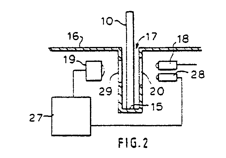
- Figure 2 shows a cross section of a part of a reading device
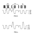
- Figure 3 illustrates the output of a photocell of the reading device of Figure 2 in relation to the data represented by code bars carried by the card and
- Figure 4 is similar to Figure 3 and illustrates the output of a photocell of the reading device for a card transparent to visible light.
- Referring first to Figure 1, a card or
badge 10 comprises aninner layer 11 sandwiched betweenouter layers inner layer 11 is PVC sheet. Theinner layer 11 has printed thereon, in ink which is opaque to infra-red radiation, a plurality ofcode bars 14 representing a string of binary data bits. The form of thecode bars 14 representing the data bits will be described in more detail hereinafter. After printing of thecode bars 14 theinner layer 11 andouter layers code bars 14 lying internally of the card orbadge 10. Theouter layers inner layer 11 has been bonded between theouter layers code bars 14 are hidden from visual inspection with visible light. Thecode bars 14 are arranged along a track extending parallel to areference edge 15 of the card so that when thecard 10 is guided through a reading device by engagement of thereference edge 15 of the card with a guide surface of the reading device, the code bars pass successively past a sensing position. - Figure 2 shows, in cross section, a part of a card reading device having an outer casing 16 and a
slot 17 therein to receive thereference edge 15 of thecard 10, the card being slidable along the slot in a direction perpendicular to the plane of the drawing with thereference edge 15 of the card engaging the bottom of the slot. An infra-red source 18, such as an LED, is positioned adjacent to one side of theslot 17 and a photocell 19 is positioned adjacent to the other side of the slot. The radiation from thesource 18 passes through anaperture 20 and aslit 29 respectively in opposite side walls of theslot 17 and is received by the photocell 19. In its passage from the source to the photocell, the radiation passes through the card and is subjected to the transmissivity of that part of the card lying, at any instant, in a sensing position in the path of the radiation defined by theslit 29 in the wall of the slot. Theslit 29 is disposed in relation to the bottom of the slot such that the track of code bars carried by the card passes through the sensing position as the card is moved manually along the length of the slot. - Referring now to Figure 3, a track of
code bars 14 of a card is shown together with the output signal corresponding to the passage of the track through the sensing position defined by theslit 29. Thecode bars 14 consist of opaquewide bars 21 representing one binary value, for example binary '0', and opaquenarrow bars 22 representing the other binary value, for example binary '1'. The inner layer on which the code bars are printed is of material transparent to infra-red radiation and hence the spaces between the code bars are transparent. The width of theslit 29, in the direction of movement of the card, is smaller than the width of thewide bars 21 and is larger than the width of thenarrow bars 22. As is shown in Figure 3, the output of the photocell is at amaximum level 23 when atransparent space 24 between code bars lies in the sensing position defined by theslit 29. When awide bar 21 lies in the sensing position and substantially inhibits radiation from the source reaching the photocell, the output of the photocell is reduced substantially to a zerolevel 25. However, when anarrow bar 22 passes through the sensing position, the radiation is only partially obscured from the photocell, because thenarrow bar 22 is less wide than theslits 20, and the output of the photocell is reduced from themaximum level 23 to alevel 26 intermediate themaximum level 23 and the zerolevel 25. Preferably the relationship of the width of theslits 20 and the width of thenarrow bars 22 is chosen such that theintermediate level 26 is approximately half themaximum level 23. - By utilising opaque code bars 14 with transparent spaces therebetween, sensing of the spaces provides a substantially uniform consistent
maximum level output 23 from the photocell to give a peak reference level between the code bars. Since this reference level is obtained from sensing of transparent spaces it is independent of any variations in ink opacity, ink thickness or voids in opaque areas which may occur in printing of the code bars. Any variation in opacity of the code bars results in a change of the absolute values of thelevels levels - The use of opaque code bars spaced by transparent spaces provides advantages in obtaining better definition during the printing of the bars than is obtained when using a code consisting of transparent or partially transparent windows in an opaque area. A smaller quantity of ink or toner is used and hence there is less ink to stray into areas intended to be transparent. Also the smaller overall area of the opaque code bars absorbs less heat during any heat fixing of toner particles and hence any distortion of the sheet of plastic material, on which printing is effected, is reduced. Higher definition is obtainable when printing fine, i.e. narrow, opaque areas on a transparent background than is possible when printing a relatively large opaque area containing fine clear areas. Accordingly improved consistency of high volume printing of tracks of code is obtained and as a result the code density on the card can be increased thereby permitting the encoding of longer streams of binary data on cards without increasing the dimensions of the card.
- The construction of the card or badge is such that the encoded data is concealed from being read by the naked eye. However it is not possible to prevent all attempts at illicit reading of the code and thereby allowing duplication of the code onto another sheet of material for illicit purposes. Greater security may be provided by ensuring that only cards which have a predetermined transmissivity to light in the visible region of the spectrum but transparent, apart from the code bars, to radiation in the infra-red region give a valid reading by the reading device. The transmissivity of the card to visible light may be such that the card is opaque to all visible light or it may be selectively and partially transparent and be formed of material having visible light filtering propertiesl. The reading device is provided with an
additional radiation source 28 arranged such that radiation from it passes through theaperture 20 and slit 29 and is received by the photocell 19. Thesource 28 produces radiation in the visible region of the spectrum. When acard 10 is moved along theslot 17, the photocell 19 receives radiation from the infra-red source 18 as described hereinbefore and, if the card is opaque to light from thesource 28, the output of the photocell 19 will be as shown in Figure 3. However if the card is transparent or partially transparent to visible light from thesource 28, the light from thesource 28 will also be received by the photocell and as a result the output from the photocell will be at a level higher than thereference level 23. If desired bothsources reference level 23 and would be reduced to thereference level 23 upon sensing of aspace 24 transparent to infra-red but opaque to light from thesource 28, of a card moved through the slot. If the card is partially transparent to light from thesource 28, the output from the photocell would be reduced toward thereference level 23 by an amount determined by the transmissivity of the card to light from thesource 28. It is preferred to continuously energise the infra-red source 18 and to switch the visiblelight source 28 on and off at predetermined times in the sequence of reading the encoded data from the card. For example, thelight source 28 would be switched on for a predetermined period during sensing of some of the transparent spaces between code bars. The detection circuit 27 is provided with means operative, in response to sensing of a transparent area of the card, to energise thesource 28 and then to detect an increase in the output of the photocell 19 when thesource 28 is energised as compared with when thesource 28 is not energised. Conveniently, thesource 28 may be energised during the sensing of each third transparent area along a code track of the card. If the card has a predetermined transmissivity to visible light from thesource 28 the output of the photocell is measured to check that the card being read has the required transmissivity to light from thesource 28 thereby providing confirmation or otherwise that the card is manufactured of material to a defined standard. The visiblelight source 28 may produce radiation in a narrow band of visible light, i.e. visible light of one colour such as red, yellow or green, and like the infra-red source may be an LED. Thus the card may be manufactured of materials having not only a predetermined transmissivity to visible light but also having a predetermined transmissivity only to the colour band of light radiated by thesource 28. Thus it will be appreciated that the data encoded in the card is read by transmission of radiation in one band, i.e. infra-red, through the card, validity of the card is verified by checking the transmissivity of the card to radiation in another band of the spectrum, for example a visible colour band. The transmissivity to radiation in the other band of the spectrum may be substantially zero or may have a defined filtering characteristic to transmit a predetermined percentage of radiation within a predetermined band of radiation.
Claims (10)
Applications Claiming Priority (2)
| Application Number | Priority Date | Filing Date | Title |
|---|---|---|---|
| GB888811935A GB8811935D0 (en) | 1988-05-20 | 1988-05-20 | Card/badge for carrying data & reader therefor |
| GB8811935 | 1988-05-20 |
Publications (2)
| Publication Number | Publication Date |
|---|---|
| EP0343829A2 true EP0343829A2 (en) | 1989-11-29 |
| EP0343829A3 EP0343829A3 (en) | 1990-05-09 |
Family
ID=10637213
Family Applications (1)
| Application Number | Title | Priority Date | Filing Date |
|---|---|---|---|
| EP89304934A Withdrawn EP0343829A3 (en) | 1988-05-20 | 1989-05-16 | Card or badge for carrying data and reader therefor |
Country Status (3)
| Country | Link |
|---|---|
| EP (1) | EP0343829A3 (en) |
| JP (1) | JPH01307937A (en) |
| GB (1) | GB8811935D0 (en) |
Cited By (20)
| Publication number | Priority date | Publication date | Assignee | Title |
|---|---|---|---|---|
| WO2001018745A2 (en) * | 1999-09-07 | 2001-03-15 | American Express Travel Related Services Company, Inc. | Transparent transaction card with infrared blocking layer |
| WO2002005204A1 (en) * | 2000-07-07 | 2002-01-17 | Schlumberger Systèmes | Transparent data card |
| US6705530B2 (en) | 1999-10-01 | 2004-03-16 | Perfect Plastic Printing Corporation | Transparent/translucent financial transaction card |
| WO2004044825A1 (en) * | 2002-11-06 | 2004-05-27 | American Express Travel Related Services Company, Inc. | A transparent transaction card |
| US6749123B2 (en) | 1999-09-07 | 2004-06-15 | American Express Travel Related Services Company, Inc. | Transaction card |
| US6764014B2 (en) | 1999-09-07 | 2004-07-20 | American Express Travel Related Services Company, Inc. | Transaction card |
| US7650314B1 (en) | 2001-05-25 | 2010-01-19 | American Express Travel Related Services Company, Inc. | System and method for securing a recurrent billing transaction |
| US7746215B1 (en) | 2001-07-10 | 2010-06-29 | Fred Bishop | RF transactions using a wireless reader grid |
| US7814332B2 (en) | 2001-07-10 | 2010-10-12 | Blayn W Beenau | Voiceprint biometrics on a payment device |
| US7889052B2 (en) | 2001-07-10 | 2011-02-15 | Xatra Fund Mx, Llc | Authorizing payment subsequent to RF transactions |
| US7988038B2 (en) | 2001-07-10 | 2011-08-02 | Xatra Fund Mx, Llc | System for biometric security using a fob |
| US8001054B1 (en) | 2001-07-10 | 2011-08-16 | American Express Travel Related Services Company, Inc. | System and method for generating an unpredictable number using a seeded algorithm |
| US8071180B2 (en) | 1999-06-21 | 2011-12-06 | Cambridge University Technical Services Limited | Aligned polymer organic TFT |
| US8279042B2 (en) | 2001-07-10 | 2012-10-02 | Xatra Fund Mx, Llc | Iris scan biometrics on a payment device |
| US8289136B2 (en) | 2001-07-10 | 2012-10-16 | Xatra Fund Mx, Llc | Hand geometry biometrics on a payment device |
| US8294552B2 (en) | 2001-07-10 | 2012-10-23 | Xatra Fund Mx, Llc | Facial scan biometrics on a payment device |
| US8818907B2 (en) | 2000-03-07 | 2014-08-26 | Xatra Fund Mx, Llc | Limiting access to account information during a radio frequency transaction |
| US9024719B1 (en) | 2001-07-10 | 2015-05-05 | Xatra Fund Mx, Llc | RF transaction system and method for storing user personal data |
| US9886692B2 (en) | 2001-07-10 | 2018-02-06 | Chartoleaux Kg Limited Liability Company | Securing a transaction between a transponder and a reader |
| US10839388B2 (en) | 2001-07-10 | 2020-11-17 | Liberty Peak Ventures, Llc | Funding a radio frequency device transaction |
Families Citing this family (11)
| Publication number | Priority date | Publication date | Assignee | Title |
|---|---|---|---|---|
| US7837116B2 (en) | 1999-09-07 | 2010-11-23 | American Express Travel Related Services Company, Inc. | Transaction card |
| US8066190B2 (en) | 1999-09-07 | 2011-11-29 | American Express Travel Related Services Company, Inc. | Transaction card |
| US8548927B2 (en) | 2001-07-10 | 2013-10-01 | Xatra Fund Mx, Llc | Biometric registration for facilitating an RF transaction |
| US7705732B2 (en) | 2001-07-10 | 2010-04-27 | Fred Bishop | Authenticating an RF transaction using a transaction counter |
| US7827106B2 (en) | 2001-07-10 | 2010-11-02 | American Express Travel Related Services Company, Inc. | System and method for manufacturing a punch-out RFID transaction device |
| US9031880B2 (en) | 2001-07-10 | 2015-05-12 | Iii Holdings 1, Llc | Systems and methods for non-traditional payment using biometric data |
| US9454752B2 (en) | 2001-07-10 | 2016-09-27 | Chartoleaux Kg Limited Liability Company | Reload protocol at a transaction processing entity |
| US7735725B1 (en) | 2001-07-10 | 2010-06-15 | Fred Bishop | Processing an RF transaction using a routing number |
| US7668750B2 (en) | 2001-07-10 | 2010-02-23 | David S Bonalle | Securing RF transactions using a transactions counter |
| US6805287B2 (en) | 2002-09-12 | 2004-10-19 | American Express Travel Related Services Company, Inc. | System and method for converting a stored value card to a credit card |
| US7318550B2 (en) | 2004-07-01 | 2008-01-15 | American Express Travel Related Services Company, Inc. | Biometric safeguard method for use with a smartcard |
Citations (7)
| Publication number | Priority date | Publication date | Assignee | Title |
|---|---|---|---|---|
| US3536894A (en) * | 1965-07-23 | 1970-10-27 | Jerry E Travioli | Electronic credit card acceptor |
| GB2084929A (en) * | 1980-10-13 | 1982-04-21 | Copytex Sicherheitssyst | A method for the detection of authenticity in a data carrier and apparatus for applying said method |
| FR2496935A1 (en) * | 1980-12-24 | 1982-06-25 | Hengstler Kg | DEVICE FOR THE ELECTRONIC READING OF INFORMATION MEDIA BY MEANS OF INFRARED LIGHT |
| GB2108906A (en) * | 1981-09-16 | 1983-05-25 | Itr Int Time Ltd | Identification card with concealed coding and decoding module |
| US4583766A (en) * | 1984-05-08 | 1986-04-22 | Kenneth R. Wessel | Secure badge for infrared badge reader and process for making same |
| GB2170657A (en) * | 1985-02-05 | 1986-08-06 | Stc Plc | Semiconductor memory device |
| EP0265838A2 (en) * | 1986-10-30 | 1988-05-04 | Interflex Datensysteme GmbH | Forgery-proof code card reader system |
Family Cites Families (2)
| Publication number | Priority date | Publication date | Assignee | Title |
|---|---|---|---|---|
| JPS6464616A (en) * | 1987-09-07 | 1989-03-10 | Hitachi Ltd | Method for operation of electric cleaner |
| JPH04189335A (en) * | 1990-11-22 | 1992-07-07 | Matsushita Electric Ind Co Ltd | Cleaner |
-
1988
- 1988-05-20 GB GB888811935A patent/GB8811935D0/en active Pending
- 1988-08-03 JP JP63192868A patent/JPH01307937A/en active Pending
-
1989
- 1989-05-16 EP EP89304934A patent/EP0343829A3/en not_active Withdrawn
Patent Citations (7)
| Publication number | Priority date | Publication date | Assignee | Title |
|---|---|---|---|---|
| US3536894A (en) * | 1965-07-23 | 1970-10-27 | Jerry E Travioli | Electronic credit card acceptor |
| GB2084929A (en) * | 1980-10-13 | 1982-04-21 | Copytex Sicherheitssyst | A method for the detection of authenticity in a data carrier and apparatus for applying said method |
| FR2496935A1 (en) * | 1980-12-24 | 1982-06-25 | Hengstler Kg | DEVICE FOR THE ELECTRONIC READING OF INFORMATION MEDIA BY MEANS OF INFRARED LIGHT |
| GB2108906A (en) * | 1981-09-16 | 1983-05-25 | Itr Int Time Ltd | Identification card with concealed coding and decoding module |
| US4583766A (en) * | 1984-05-08 | 1986-04-22 | Kenneth R. Wessel | Secure badge for infrared badge reader and process for making same |
| GB2170657A (en) * | 1985-02-05 | 1986-08-06 | Stc Plc | Semiconductor memory device |
| EP0265838A2 (en) * | 1986-10-30 | 1988-05-04 | Interflex Datensysteme GmbH | Forgery-proof code card reader system |
Cited By (27)
| Publication number | Priority date | Publication date | Assignee | Title |
|---|---|---|---|---|
| US8071180B2 (en) | 1999-06-21 | 2011-12-06 | Cambridge University Technical Services Limited | Aligned polymer organic TFT |
| US6764014B2 (en) | 1999-09-07 | 2004-07-20 | American Express Travel Related Services Company, Inc. | Transaction card |
| WO2001018745A3 (en) * | 1999-09-07 | 2001-09-13 | American Express Travel Relate | Transparent transaction card with infrared blocking layer |
| WO2001018745A2 (en) * | 1999-09-07 | 2001-03-15 | American Express Travel Related Services Company, Inc. | Transparent transaction card with infrared blocking layer |
| US7377443B2 (en) | 1999-09-07 | 2008-05-27 | American Express Travel Related Services Company, Inc. | Transaction card |
| AU781322B2 (en) * | 1999-09-07 | 2005-05-19 | American Express Travel Related Services Company, Inc. | Transaction card |
| US6749123B2 (en) | 1999-09-07 | 2004-06-15 | American Express Travel Related Services Company, Inc. | Transaction card |
| US6705530B2 (en) | 1999-10-01 | 2004-03-16 | Perfect Plastic Printing Corporation | Transparent/translucent financial transaction card |
| EP1581846A4 (en) * | 1999-10-01 | 2005-10-05 | American Express Travel Relate | Transparent/translucent financial transaction card |
| US6732936B1 (en) | 1999-10-01 | 2004-05-11 | Perfect Plastic Printing Corp. | Transparent/translucent financial transaction card |
| US8818907B2 (en) | 2000-03-07 | 2014-08-26 | Xatra Fund Mx, Llc | Limiting access to account information during a radio frequency transaction |
| WO2002005204A1 (en) * | 2000-07-07 | 2002-01-17 | Schlumberger Systèmes | Transparent data card |
| US7650314B1 (en) | 2001-05-25 | 2010-01-19 | American Express Travel Related Services Company, Inc. | System and method for securing a recurrent billing transaction |
| US7746215B1 (en) | 2001-07-10 | 2010-06-29 | Fred Bishop | RF transactions using a wireless reader grid |
| US8289136B2 (en) | 2001-07-10 | 2012-10-16 | Xatra Fund Mx, Llc | Hand geometry biometrics on a payment device |
| US7988038B2 (en) | 2001-07-10 | 2011-08-02 | Xatra Fund Mx, Llc | System for biometric security using a fob |
| US8001054B1 (en) | 2001-07-10 | 2011-08-16 | American Express Travel Related Services Company, Inc. | System and method for generating an unpredictable number using a seeded algorithm |
| US7814332B2 (en) | 2001-07-10 | 2010-10-12 | Blayn W Beenau | Voiceprint biometrics on a payment device |
| US8074889B2 (en) | 2001-07-10 | 2011-12-13 | Xatra Fund Mx, Llc | System for biometric security using a fob |
| US8279042B2 (en) | 2001-07-10 | 2012-10-02 | Xatra Fund Mx, Llc | Iris scan biometrics on a payment device |
| US7889052B2 (en) | 2001-07-10 | 2011-02-15 | Xatra Fund Mx, Llc | Authorizing payment subsequent to RF transactions |
| US8294552B2 (en) | 2001-07-10 | 2012-10-23 | Xatra Fund Mx, Llc | Facial scan biometrics on a payment device |
| US10839388B2 (en) | 2001-07-10 | 2020-11-17 | Liberty Peak Ventures, Llc | Funding a radio frequency device transaction |
| US9024719B1 (en) | 2001-07-10 | 2015-05-05 | Xatra Fund Mx, Llc | RF transaction system and method for storing user personal data |
| US9336634B2 (en) | 2001-07-10 | 2016-05-10 | Chartoleaux Kg Limited Liability Company | Hand geometry biometrics on a payment device |
| US9886692B2 (en) | 2001-07-10 | 2018-02-06 | Chartoleaux Kg Limited Liability Company | Securing a transaction between a transponder and a reader |
| WO2004044825A1 (en) * | 2002-11-06 | 2004-05-27 | American Express Travel Related Services Company, Inc. | A transparent transaction card |
Also Published As
| Publication number | Publication date |
|---|---|
| GB8811935D0 (en) | 1988-06-22 |
| JPH01307937A (en) | 1989-12-12 |
| EP0343829A3 (en) | 1990-05-09 |
Similar Documents
| Publication | Publication Date | Title |
|---|---|---|
| EP0343829A2 (en) | Card or badge for carrying data and reader therefor | |
| US4538059A (en) | Identification card with concealed coding and a simple reader module to decode it | |
| EP0866420A2 (en) | Identification card or badge | |
| US4544184A (en) | Tamper-proof identification card and identification system | |
| US5463212A (en) | Latent image forming member and method of manufacturing, latent image reading apparatus and latent image reading system | |
| US4013894A (en) | Secure property document and system | |
| US4034211A (en) | System and method for providing a security check on a credit card | |
| GB2108906A (en) | Identification card with concealed coding and decoding module | |
| CA1200385A (en) | Optically-readable cards | |
| US4066910A (en) | Transmissivity-coded data card systems | |
| CA2198880A1 (en) | Authenticating data storage articles | |
| US6384409B1 (en) | Optical tracking system | |
| US3604901A (en) | Information card | |
| US3858031A (en) | Credit card having clear middle layer encoded by discrete opaque areas and system for decoding same by laser beam | |
| US4678898A (en) | Identification card with improved concealed coding and an optical swipe reader housing for use with it | |
| KR930003424B1 (en) | Magnetic recording card and its data recording method | |
| US6981648B1 (en) | Information carrier medium and reader for reading the information carrier medium | |
| GB2214679A (en) | Verification | |
| WO1995013196A1 (en) | Coded indentification card and other standardized documents | |
| WO1993017402A1 (en) | System for detecting holes punched in the magnetic card | |
| JP3021589B2 (en) | Information recording medium | |
| CA1207457A (en) | Identification card with concealed coding and a simple reader module to decode it | |
| GB2201126A (en) | Security documents | |
| JPS60173722A (en) | Magnetic card | |
| JPH05197848A (en) | Information recording medium |
Legal Events
| Date | Code | Title | Description |
|---|---|---|---|
| PUAI | Public reference made under article 153(3) epc to a published international application that has entered the european phase |
Free format text: ORIGINAL CODE: 0009012 |
|
| AK | Designated contracting states |
Kind code of ref document: A2 Designated state(s): AT DE ES FR GB IT SE |
|
| PUAL | Search report despatched |
Free format text: ORIGINAL CODE: 0009013 |
|
| AK | Designated contracting states |
Kind code of ref document: A3 Designated state(s): AT DE ES FR GB IT SE |
|
| 17P | Request for examination filed |
Effective date: 19901029 |
|
| 17Q | First examination report despatched |
Effective date: 19921117 |
|
| STAA | Information on the status of an ep patent application or granted ep patent |
Free format text: STATUS: THE APPLICATION IS DEEMED TO BE WITHDRAWN |
|
| 18D | Application deemed to be withdrawn |
Effective date: 19930330 |