EP0344606A2 - Collapsible needle cover - Google Patents
Collapsible needle cover Download PDFInfo
- Publication number
- EP0344606A2 EP0344606A2 EP89109403A EP89109403A EP0344606A2 EP 0344606 A2 EP0344606 A2 EP 0344606A2 EP 89109403 A EP89109403 A EP 89109403A EP 89109403 A EP89109403 A EP 89109403A EP 0344606 A2 EP0344606 A2 EP 0344606A2
- Authority
- EP
- European Patent Office
- Prior art keywords
- needle
- cover
- cannula
- segments
- syringe
- Prior art date
- Legal status (The legal status is an assumption and is not a legal conclusion. Google has not performed a legal analysis and makes no representation as to the accuracy of the status listed.)
- Granted
Links
- 239000012530 fluid Substances 0.000 claims abstract description 11
- 230000000149 penetrating effect Effects 0.000 claims 2
- 238000002347 injection Methods 0.000 abstract description 21
- 239000007924 injection Substances 0.000 abstract description 21
- 201000010099 disease Diseases 0.000 abstract description 7
- 208000037265 diseases, disorders, signs and symptoms Diseases 0.000 abstract description 7
- 230000002708 enhancing effect Effects 0.000 abstract description 4
- 230000006378 damage Effects 0.000 abstract 1
- 210000003811 finger Anatomy 0.000 description 15
- 238000000034 method Methods 0.000 description 5
- 230000000717 retained effect Effects 0.000 description 3
- 239000003814 drug Substances 0.000 description 2
- 229940079593 drug Drugs 0.000 description 2
- 208000015181 infectious disease Diseases 0.000 description 2
- 208000030507 AIDS Diseases 0.000 description 1
- 208000035473 Communicable disease Diseases 0.000 description 1
- 239000004743 Polypropylene Substances 0.000 description 1
- 230000000712 assembly Effects 0.000 description 1
- 238000000429 assembly Methods 0.000 description 1
- 238000009534 blood test Methods 0.000 description 1
- 230000009977 dual effect Effects 0.000 description 1
- 230000002458 infectious effect Effects 0.000 description 1
- 230000002452 interceptive effect Effects 0.000 description 1
- 239000000463 material Substances 0.000 description 1
- 238000012986 modification Methods 0.000 description 1
- 230000004048 modification Effects 0.000 description 1
- 230000037368 penetrate the skin Effects 0.000 description 1
- -1 polypropylene Polymers 0.000 description 1
- 229920001155 polypropylene Polymers 0.000 description 1
- 230000005855 radiation Effects 0.000 description 1
- 238000012360 testing method Methods 0.000 description 1
- 210000003813 thumb Anatomy 0.000 description 1
- 239000011782 vitamin Substances 0.000 description 1
- 229940088594 vitamin Drugs 0.000 description 1
- 229930003231 vitamin Natural products 0.000 description 1
- 235000013343 vitamin Nutrition 0.000 description 1
- 150000003722 vitamin derivatives Chemical class 0.000 description 1
- 239000002699 waste material Substances 0.000 description 1
Images


Classifications
-
- A—HUMAN NECESSITIES
- A61—MEDICAL OR VETERINARY SCIENCE; HYGIENE
- A61M—DEVICES FOR INTRODUCING MEDIA INTO, OR ONTO, THE BODY; DEVICES FOR TRANSDUCING BODY MEDIA OR FOR TAKING MEDIA FROM THE BODY; DEVICES FOR PRODUCING OR ENDING SLEEP OR STUPOR
- A61M5/00—Devices for bringing media into the body in a subcutaneous, intra-vascular or intramuscular way; Accessories therefor, e.g. filling or cleaning devices, arm-rests
- A61M5/178—Syringes
- A61M5/31—Details
- A61M5/32—Needles; Details of needles pertaining to their connection with syringe or hub; Accessories for bringing the needle into, or holding the needle on, the body; Devices for protection of needles
- A61M5/3205—Apparatus for removing or disposing of used needles or syringes, e.g. containers; Means for protection against accidental injuries from used needles
- A61M5/321—Means for protection against accidental injuries by used needles
- A61M5/3243—Means for protection against accidental injuries by used needles being axially-extensible, e.g. protective sleeves coaxially slidable on the syringe barrel
- A61M5/3275—Means for protection against accidental injuries by used needles being axially-extensible, e.g. protective sleeves coaxially slidable on the syringe barrel being connected to the needle hub or syringe by radially deflectable members, e.g. longitudinal slats, cords or bands
-
- A—HUMAN NECESSITIES
- A61—MEDICAL OR VETERINARY SCIENCE; HYGIENE
- A61M—DEVICES FOR INTRODUCING MEDIA INTO, OR ONTO, THE BODY; DEVICES FOR TRANSDUCING BODY MEDIA OR FOR TAKING MEDIA FROM THE BODY; DEVICES FOR PRODUCING OR ENDING SLEEP OR STUPOR
- A61M5/00—Devices for bringing media into the body in a subcutaneous, intra-vascular or intramuscular way; Accessories therefor, e.g. filling or cleaning devices, arm-rests
- A61M5/178—Syringes
- A61M5/31—Details
- A61M5/32—Needles; Details of needles pertaining to their connection with syringe or hub; Accessories for bringing the needle into, or holding the needle on, the body; Devices for protection of needles
- A61M5/3205—Apparatus for removing or disposing of used needles or syringes, e.g. containers; Means for protection against accidental injuries from used needles
- A61M5/321—Means for protection against accidental injuries by used needles
- A61M5/3243—Means for protection against accidental injuries by used needles being axially-extensible, e.g. protective sleeves coaxially slidable on the syringe barrel
- A61M5/3245—Constructional features thereof, e.g. to improve manipulation or functioning
- A61M2005/3247—Means to impede repositioning of protection sleeve from needle covering to needle uncovering position
Definitions
- This invention relates to a safety enhancing and relatively low-cost needle cover which is integrally connected to a disposable needle cannula of a hypodermic syringe, wherein the cover is collapsible from an open, expanded configuration, at which the cannula is exposed for administering an injection, to a closed, generally planar configuration, at which the cannula is completely surrounded, shielded, and isolated after use.
- Hypodermic syringes are used for a variety of purposes.
- the syringe may be used to expulse fluid medication to a patient by way of a hypodermic needle cannula.
- the syringe may be used to treat a patient with a communicable disease.
- the needle cannula thereof Prior to disposal of the syringe, the needle cannula thereof is sometimes broken to prevent reuse.
- Health care workers are especially susceptible to accidental and potentially infectious needle strikes due to the careless handling or breaking of the cannula and disposing of the syringe after use.
- the resulting mini-accidents caused by an inadvertent needle strike typically require a blood test for such diseases as AIDS and Hepatitus.
- the corresponding cost and inefficiency of testing health care workers who have received an inadvertent needle strike result in considerable waste, which may be particularly damaging to a health care facility which is striving for economy.
- this invention relates to a safety enhancing, relatively low-cost, needle cover which is integrally bonded to and collapsible around a disposable, single use needle cannula.
- the combination cannula and collapsible needle cover is detachably connected to the distal bore of a hypodermic syringe.
- the combination cannula and collapsible needle cover is integrally connected to the distal bore of a syringe so as to form a one-piece, disposable syringe assembly.
- the needle cover of the present invention comprises distally and proximally oriented pairs of needle cover segments, each of which segments being joined to an adjacent segment by means of an integral hinge around which said cover segments pivot.
- the needle cover is collapsible from an open, expanded configuration, at which the needle cannula is biased in an armed state for administering an injection, to a closed, generally planar configuration, at which the needle cannula is biased in a shielded state, to be completely surrounded and isolated by the cover.
- a pair of oppositely disposed, rotatable motion transferring arms is connected to the needle cover so that a health care worker may manually and selectively move the cover between the open and closed configurations.
- a locking catch is connected to one of the needle cover segments and is adapted to move into respective engagement with adjacent cover segments to either releasably retain the needle cover in the open configuration with the cannula in the armed state or permanently lock the needle cover in the closed configuration with the cannula in the shielded state. Accordingly, the needle cannula may be safely disposed of after use within its collapsible cover to avoid subjecting the health care worker to an accidental needle strike and the spread of a contagious, and possibly life threatening, disease.
- the needle cover may be formed from distally and proximally oriented pairs of needle cover segments and intermediate cover segments located therebetween.
- the cover segments are pivotally interconnected with one another at respective, integral hinges to permit the needle cover to be moved between the open, expanded configuration and the closed, substantially planar configuration.
- the needle cover of this embodiment is characterized by a minimized lateral width in the open configuration to facilitate the positioning of the syringe and the alignment of the needle cannula during the administration of an injection.
- the needle cover is provided with a pair of axially projecting resilient fingers which engage the needle cannula and function as spring locks to releasably retain the cover in the open, expanded configuration so that an injection may be administered.
- the resilient fingers slide rearwardly along the cannula to cause the needle cover to be continuously rotated and automatically snapped-locked in a swept-back, over center configuration without the addition of a separate locking element.
- FIGs. 1-5 of the drawings show the needle cover 1 detachably connected to the distal bore of the hollow cylinder 3 of a conventional hypodermic syringe (shown in phantom and represented by the reference numeral 2).
- the needle cover 1 is preferably, but not necessarily, fabricated from a radiation grade polypropylene material.
- FIG. 1 shows the needle cover 1 in a closed, generally planar configuration so as to completely surround, shield, and isolate a needle cannula 4 and thereby prevent an accidental needle strike and the spread of a contagious, and possibly life threatening disease.
- FIG. 1 shows the needle cover 1 in a closed, generally planar configuration so as to completely surround, shield, and isolate a needle cannula 4 and thereby prevent an accidental needle strike and the spread of a contagious, and possibly life threatening disease.
- the needle cover 1 shows the needle cover 1 in an open, expanded configuration to expose the cannula 4 and thereby permit said cannula to either communicate with a source of fluid (so that the syringe 2 may be infused with a medication, vitamin, or the like) or penetrate the skin of a patient (so that an injection may be administered according to medically accepted techniques).
- a source of fluid so that the syringe 2 may be infused with a medication, vitamin, or the like
- an injection may be administered according to medically accepted techniques.
- the collapsible needle cover 1 and needle cannula 4 are integrally connected to one another so as to be attached to or removed from the syringe 2 as a one piece, combination cannula/cover.
- the needle cover 1 is shown comprising distally and proximally oriented pairs of needle cover segments 6-1 and 6-2.
- Each needle cover segment 6-1 and 6-2 is joined to its adjacent segment by means of a respective, integral hinge 7 around which the cover pivots when moving between the closed and open configurations of FIGs. 1 and 2.
- a narrow orifice 8 is established through the hinge 7 at the intersection of the distally oriented cover segments 6-1, so as to receive the distal end of needle cannula 4 therethrough when the needle cover 1 is moved to the open, expanded configuration of FIG. 2.
- the proximally oriented pair of needle cover segments 6-2 are connected to a needle support 10 by means of integral hinges 9.
- a conventional luer lock fitting 12 projects proximally from the needle support 10.
- the luer lock fitting 12 of needle cover 1 is interconnected (i.e. rotated into engagement) with the distal bore of the syringe cylinder 3 whereby to detachably connect the needle cover 1 to the syringe 2.
- the needle support 10 is integrally connected (e.g. molded or thermally bonded) to the needle cannula 4 so as to support and retain the cannula in coaxial alignment with the luer lock fitting 12 and the cylinder 3 of syringe 2.
- the needle cover 1 and needle cannula 4 are packed and shipped to health care facilities as a single piece, combination cannula/cover. Moreover, and in the assembled relationship, the proximal end of cannula 4 communicates with the interior with the syringe cylinder 3 via the luer lock fitting 12, whereby the cylinder may be infused with fluid or fluid may be expulsed from the cylinder (with the needle cover 1 in the open, expanded configuration of FIG. 2).
- a pair of motion transferring arms 14 projects outwardly and in opposite directions from respective proximally oriented needle cover segments 6-2.
- the motion transferring arms 14 may be manually rotated towards one another, whereby to cause the needle cover segments 6-1 and 6-2 to pivot around their respective hinges 8 and 9 and thereby cause needle cover 1 to move from the closed, substantially planar configuration of FIG. 1, to the open, expanded configuration of FIG. 2, such that needle cannula 4 is biased in an armed state from a shielded state.
- a locking catch 16 extends from one of the proximally oriented cover segments 6-2.
- a first notch 18 is formed in the other of the proximally oriented cover segments 6-2.
- a second notch 20 is formed in the distally oriented cover segment 6-1 which lies immediately above and is contiguous with the proximally oriented cover segment 6-2 from which locking catch 16 extends.
- the locking catch 16 performs a dual function. In a first case, locking catch 16 is rotated through notch 20 to automatically and releasibly retain needle cover 1 in the open, expanded configuration of FIGs. 2 and 4 and thereby permit the cylinder 3 of syringe 2 to be infused with fluid for the purpose of administering an injection.
- locking catch 16 is rotated through notch 18 to automatically lock needle cover 1 in the closed, substantially planar configuration of FIGs. 1 and 5, whereby the needle cannula 4 is surrounded, shielded, and isolated to permit the cannula to be safely handled and discarded after use while avoiding an accidental needle strike.
- FIG. 3 shows the needle cover 1 immediately after its removal from a package in which said cover is transported to a health care facility. More particularly, a pre-sterilized needle cover 1 is packed in a substantially collapsed condition with the needle cover segments 6-1 and 6-2 thereof pivoted around their respective hinges 7 and 9 to the closed, generally planar configuration to surround needle cannula 4.
- needle cannula 4 may be biased in the armed state (of FIG. 4) from the shielded state (of FIG.
- the locking catch 16 is located next to, but outside, the notch 18 in the adjacent proximally oriented cover segment 6-2. That is to say, the needle cover 1 is moved to but not locked in the closed, generally planar configuration.
- the combination needle cover 1/needle cannula 4 is removed from its package with the cover in the collapsed configuration and the needle cannula 4 in the shielded state.
- the cover is then removably attached to the syringe 2 by rotating the luer lock fitting 12 of the cover into engagement with the distal bore of the syringe cylinder 3.
- the needle cover 1 is moved out of the collapsed condition, so that needle cannula 4 can be biased in the armed state. More particularly, with the needle cover 1 attached to the cylinder 3 of syringe 2, the health care worker applies an axially and proximally directed force to each of the pair of motion transferring arms 14 (in the direction of the reference arrows 22 of FIG. 3). Accordingly, the arms 14 will rotate towards one another in a generally proximal direction, whereby to correspondingly cause needle cover segments 6-1 and 6-2 to pivot around their respective hinges 7 and 9 for movement to the open, expanded configuration of FIG. 4.
- the locking catch 16 which extends from a proximally oriented cover segment 6-2 is advanced through the notch 20, whereby to be automatically snapped into engagement with its adjacent, contiguously disposed and distally oriented cover segment 6-1 in which the notch 20 is formed to releasably and reliably retain needle cover 1 in the open, expanded configuration.
- the distal end of needle cannula 4 extends through the opening 8 in the hinge 7 between adjacent distally oriented cover segments 6-1, so that cannula 4 is held in the armed state at which syringe cylinder 3 is infused with fluid for subsequent injection through the skin of a patient.
- the needle cover 1 is again collapsed whereby cover segments 6-1 and 6-2 are returned to the closed, generally planar configuration and needle cannula 4 is biased in the shielded state. More particularly, the health care worker detaches the locking catch 16 from (i.e. rotates locking catch 16 out of engagement with) the distally oriented needle cover segment 6-1, such that the catch is moved out of notch 20.
- the health care worker then applies equal and opposite, laterally directed forces (in the direction of the reference arrows 26) to the proximally oriented needle cover segment 6-2 to cause the segments 6-1 and 6-2 to pivot around their respective hinges 7 and 9 and thereby collapse needle cover 1 around needle cannula 4.
- the continued application of the laterally directed forces advances locking catch 16 through the notch 18 in the proximally oriented cover segment 6-2 in which said notch is formed.
- locking catch 16 is automatically snapped into engagement with cover segment 6-2, whereby to permanently lock needle cover 1 in the closed, generally planar configuration with needle cannula 4 biased in the shielded state.
- the needle cover segments 6-1 and 6-2 surround, shield and isolate the cannula 4 so that the syringe 2 may be safely handled without subjecting the health care worker to an accidental needle strike and the spread contagious and possibly life-threatening disease.
- the locking catch 16 prevents the inadvertent return of the needle cover 1 to the open, expanded configuration (of FIG. 4), needle cover 1 may be detached from syringe cylinder 3.
- the needle cannula 4 need not be directly handled, cut, or otherwise destroyed after use, but may be conveniently and safely discarded in the shielded state of FIG. 5 within the collapsed needle cover 1.
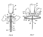
- FIGs. 6 and 7 of the drawings A collapsible needle cover 31 according to a second embodiment of the present invention is now described while referring to FIGs. 6 and 7 of the drawings.
- the needle cover 31 of FIGs. 6 and 7 is integrally connected (e.g. molded or bonded) to a needle cannula 34.
- needle cover 31 is also integrally connected to the distal bore of a cylinder 33 from a syringe 32 so as to form a one-piece, disposable syringe assembly.
- Needle cover 31 comprises distally and proximally oriented pairs of needle cover segments 36-1 and 36-2 which are hingedly interconnected with one another and adapted to pivot when cover 31 is moved between the closed and open configurations. That is, FIG. 6 shows the needle cover 36 in a closed, generally planar configuration with the needle cover segments 36-1 and 36-2 completely surrounding, shielding, and isolating the cannula 34 so as to prevent an accidental needle strike. FIG. 7 shows the needle cover 31 in the open, expanded configuration to expose the cannula 34 through an orifice 38 in the cover 31 and thereby permit the fluid contents of syringe 33 to be injected through the skin of a patient.
- a pair of force transferring arms 44 project outwardly and in opposite directions from respective proximally oriented needle cover segments 36-2.
- axially and proximally directed forces may be manually applied to the motion transferring arms 44 (in the direction of the reference arrows 46 of FIG. 6) to cause said arms to rotate, whereby needle cover segments 36-1 and 36-2 are correspondingly pivoted around their respective hinges.
- the needle cover 31 is moved to the open, expanded configuration of FIG. 7 with needle cannula 34 biased in the armed state.
- a description of the return of needle cover 31 to the closed, generally planar configuration of FIG. 6 with needle cannula 34 in the shielded state is similar to that which was previously provided when referring to FIG. 5. Therefore, for purposes of brevity, this description will be omitted.
- FIGs. 8-10 of the drawings illustrate a collapsible and disposable needle cover 60 formed in accordance with a third embodiment of the present invention. It is preferable that the needle cover 60 of the present embodiment include a needle cannula 62 that is integrally connected (e.g. molded or bonded) to a needle supporting hub 64 having a liner lock fitting.
- a needle cannula 62 that is integrally connected (e.g. molded or bonded) to a needle supporting hub 64 having a liner lock fitting.
- a one-piece combination needle cannula and collapsible needle cover is provided that is adapted to be removably attached to the distal end of a conventional syringe (shown in phantom and represented by the reference numeral 66), whereby cannula 62 may be shielded and removed from the syringe 60 after use to permit the cannula to be safely handled and discarded while avoiding an accidental needle strike and the possible spread of a contagious disease.
- Needle cover 60 comprises distally and proximally oriented pairs of needle cover segments 68 and 70. Needle cover segments 68 and 70 are hingedly interconnected with intermediate needle cover segments 72, such that the needle cover segments 68, 70 and 72 are adapted to pivot relative to one another when the needle cover 60 is moved between the closed and open configurations.
- FIG. 8 shows the needle cover 60 in a closed, generally planar configuration with the distal, proximal and intermediate cover segments 68, 70 and 72 completely surrounding, shielding and isolating the cannula 62 so as to prevent an accidental needle strike.
- FIG. 10 shows the needle cover 60 in an open, expanded configuration to expose the cannula 62 through an opening 74 in the cover to permit the contents of syringe 66 to be injected into a targeted tissue area of the patient.
- one of the distal cover segments 68 is pivotally connected at an integral hinge 75 with a first intermediate cover segments 72-1.
- Intermediate cover segment 72-1 extends continuously from integral hinge 75 to an integral hinge 76 formed with one of the proximal cover segments 70.
- the other distal cover segment 68 is pivotally connected at an integral hinge 77 with a second intermediate cover segment 72-2.
- Intermediate cover segment 72-2 is also hingedly connected to the first intermediate cover segment 72-1.
- a third intermediate cover segment 72-3 is connected from an integral hinge 78 with the other proximal needle cover segment 70 to the first intermediate cover segment 72-1.
- Each of the proximal cover segments 70 is also hingedly connected to the hub 64, such that the hub 64 and needle cover 60 are integrally connected together.
- Each of the distal cover segments 68 is also pivotally connected together at an integral hinge through which the opening 74 is formed for receiving the needle cannula 62.
- the hingedly connected distal, proximal and intermediate cover segments 68, 70 and 72 will be aligned with one another to form a figure "8" when the needle cover 60 is collapsed from the closed, planar configuration (of FIG. 8) to the open, expanded configuration (of FIG. 10).
- the advantage of the hereinabove disclosed arrangement of pivotally interconencted needle cover segments is that the lateral width of needle cover 60 will be minimized relative to the needle covers 1 and 31 of FIGs. 1-7 when said needle cover 60 is located in the open, expanded configuration of FIG. 10 for administering an injection.
- the needle cover 60 which is characterized by reduced lateral width, will make the process of administering the injection easier and more reliable and permit the health care worker to make a veni puncture through the patient's skin without interfering with the bevel orientation of the cutting surface of cannula 62.
- a pair of motion transferring arms 80 project outwardly and in opposite directions from respective proximally oriented needle cover segments 70.
- Axially and proximally directed forces may be manually applied to motion transferring arms 80 (in the direction of the reference arrows 82 of FIG. 9) to cause said arms to rotate, whereby the proximal, distal and intermediate needle cover segments 68, 70 and 72 are correspondingly pivoted around their respective hinges.
- the needle cover 60 is moved (in the direction of the reference arrow 84 of FIG. 9) to the open, expanded configuration of FIG. 10 with needle cannula 62 biased in the armed state through opening 74.
- the continued application of force to motion transferring arms 78 also causes a locking catch 86, which extends from one of the proximally oriented cover segments 70, to be advanced towards and rotated into a notch 88 formed in one of the distally oriented cover segments 68, whereby catch 86 is snapped into engagement with cover segment 68.
- the needle cover 60 is shown in FIG. 10 releasably retained in the open, expanded configuration of relatively small lateral width so that an injection may be efficiently administered.
- a description of the process for detaching locking catch 86 from the notch 88 and collapsing the needle cover 60 to the closed, generally planar configuration of FIG. 8 with needle cannula 62 in the shielded state (suitable to permit the combination needle cover and cannula to be removed from syringe 66 and safely discarded after use) is similar to the process described when previously referring to FIG. 5. Therefore, this process will not be described again.
- FIGs. 11-13 of the drawings illustrate a collapsible needle cover 90 according to a fourth embodiment of the present invention.
- Needle cover 90 includes a needle cannula 92 and needle supporting hub 94 which are integrally interconnected with needle cover 90 to form a one piece disposable needle cannula and collapsible needle cover that is adapted to be attached to the distal end of a conventional syringe (shown in phantom and represented by reference numeral 96) or removed from the syringe and safely discarded with the cannula 92 surrounded and shielded after use.
- Needle cover 90 also includes pairs of distally and proximally oriented needle cover segments 97 and 99 which are pivotally interconnected with one another by means of integral hinges.
- the needle cover 90 is adapted to be moved between a closed, substantially planar configuration (of FIG. 11) at which to surround and shield the cannula 92, and an open, expanded configuration (of FIG. 13), at which the cannula 92 is exposed through an opening in the needle cover to permit the contents of the syringe 96 to be injected into a targeted tissue area of the patient.
- the needle cover 90 is provided with a pair of axially projecting resilient fingers 100 which, as will soon be explained, act as spring locks that cooperate with cannula 92 to releasably retain the needle cover 90 in the open, expanded configuration (of FIG. 13) so that an injection may be administered.
- cover 90 can be automatically and reliably locked in the open configuration by means of the fingers 100 without the inclusion of an additional locking catch (such as that designated by reference numeral 16 in FIG. 4).
- each finger 100 is coextensively formed with and projected outwardly from a respective distal needle cover segment 97.
- fingers 100 In the closed, planar configuration of FIG. 11, fingers 100 extend in generally spaced, parallel alignment with one another and with the needle cannula 92 which is located therebetween.
- the fingers 100 will correspondingly rotate into contact with and slide along needle cannula 92 as the needle cover 90 is positioned in the open, expanded configuration of FIG. 13. That is, the fingers 100 are disposed opposite one another to grip the cannula 92 therebetween, such that the fingers slide axially and proximally along cannula 92 as needle cover 90 is moved to the expanded configuration.
- the distally and proximally oriented needle cover segments 97 and 99 are pivoted relative to one another to assume a swept back, over-center configuration. That is to say, cover segments 97 and 99 are rotated in a generally rearward direction and past a horizontal reference line (designated by reference numeral 104 of FIG. 13).
- the aforementioned swept back, over-center configuration is achieved by aligning the motion transferring arms 102 in a slightly forward direction (best shown in FIG.
- the health care worker applies a sufficient forward (i.e. axial and distal) pressure to the needle cover 90 to overcome the locking force exerted by resilient fingers 100. Accordingly, the needle cover 90 is moved out of the open configuration and collapsed towards the closed configuration (of FIG. 11), whereby to surround and shield the cannula 92 after use. The needle cover 90 may then be removed from the syringe 96 and safely discarded without subjecting the health care worker to an accidental, and possibly life-threatening, needle strike.
- a reliable, safely enhancing needle cover is available which is integrally connected to a needle cannula and easily manipulated between open and closed configurations, whereby either an injection may be administered or the cannula may be completely surrounded, shielded, and isolated so as to be suitable for disposal after a single use without requiring the needle to be handled, cut or destroyed. Accordingly, a health care worker will not be subjected to the risk of an accidental needle strike and the spread of a contagious and life-threatening disease.
Abstract
Description
- This invention relates to a safety enhancing and relatively low-cost needle cover which is integrally connected to a disposable needle cannula of a hypodermic syringe, wherein the cover is collapsible from an open, expanded configuration, at which the cannula is exposed for administering an injection, to a closed, generally planar configuration, at which the cannula is completely surrounded, shielded, and isolated after use.
- Hypodermic syringes are used for a variety of purposes. By way of example, the syringe may be used to expulse fluid medication to a patient by way of a hypodermic needle cannula. However, the syringe may be used to treat a patient with a communicable disease. Prior to disposal of the syringe, the needle cannula thereof is sometimes broken to prevent reuse. Health care workers are especially susceptible to accidental and potentially infectious needle strikes due to the careless handling or breaking of the cannula and disposing of the syringe after use. The resulting mini-accidents caused by an inadvertent needle strike typically require a blood test for such diseases as AIDS and Hepatitus. The corresponding cost and inefficiency of testing health care workers who have received an inadvertent needle strike result in considerable waste, which may be particularly damaging to a health care facility which is striving for economy.
- The following United States patents disclose various needle cover arrangements:
3,840̸,0̸0̸8 October 8, 1974 3,884,230̸ May 20̸, 1975 4,139,0̸0̸9 February 13, 1979 4,30̸3,0̸69 December 1, 1981 4,664,653 May 12, 1987 4,725,267 February 16, 1988 4,735,618 April 5, 1988 - In general terms, this invention relates to a safety enhancing, relatively low-cost, needle cover which is integrally bonded to and collapsible around a disposable, single use needle cannula. In a first embodiment of the invention, the combination cannula and collapsible needle cover is detachably connected to the distal bore of a hypodermic syringe. In a second embodiment, the combination cannula and collapsible needle cover is integrally connected to the distal bore of a syringe so as to form a one-piece, disposable syringe assembly.
- The needle cover of the present invention comprises distally and proximally oriented pairs of needle cover segments, each of which segments being joined to an adjacent segment by means of an integral hinge around which said cover segments pivot. The needle cover is collapsible from an open, expanded configuration, at which the needle cannula is biased in an armed state for administering an injection, to a closed, generally planar configuration, at which the needle cannula is biased in a shielded state, to be completely surrounded and isolated by the cover. A pair of oppositely disposed, rotatable motion transferring arms is connected to the needle cover so that a health care worker may manually and selectively move the cover between the open and closed configurations.
- A locking catch is connected to one of the needle cover segments and is adapted to move into respective engagement with adjacent cover segments to either releasably retain the needle cover in the open configuration with the cannula in the armed state or permanently lock the needle cover in the closed configuration with the cannula in the shielded state. Accordingly, the needle cannula may be safely disposed of after use within its collapsible cover to avoid subjecting the health care worker to an accidental needle strike and the spread of a contagious, and possibly life threatening, disease.
- In an additional embodiment of the invention, the needle cover may be formed from distally and proximally oriented pairs of needle cover segments and intermediate cover segments located therebetween. The cover segments are pivotally interconnected with one another at respective, integral hinges to permit the needle cover to be moved between the open, expanded configuration and the closed, substantially planar configuration. The needle cover of this embodiment is characterized by a minimized lateral width in the open configuration to facilitate the positioning of the syringe and the alignment of the needle cannula during the administration of an injection.
- In yet another embodiment of the invention, the needle cover is provided with a pair of axially projecting resilient fingers which engage the needle cannula and function as spring locks to releasably retain the cover in the open, expanded configuration so that an injection may be administered. The resilient fingers slide rearwardly along the cannula to cause the needle cover to be continuously rotated and automatically snapped-locked in a swept-back, over center configuration without the addition of a separate locking element.
-
- FIG. 1 shows the collapsible needle cover according to a first embodiment of the invention detachably connected to the distal bore of a hypodermic syringe and moved to a closed, generally planar configuration for surrounding and shielding a disposable needle cannula;
- FIG. 2 shows the collapsible needle cover of FIG. 1 in an open, generally expanded configuration to expose the needle cannula for the purpose of administering an injection of the fluid contents of the syringe;
- FIGs. 3-5 illustrate the details for operating the needle cover of FIG. 1;
- FIGs. 6 and 7 show the collapsible needle cover according to a second embodiment of the invention integrally connected to the distal bore of a hypodermic syringe to form a one-piece, disposable syringe assembly;
- Figs. 8-10 show the collapsible needle cover according to a third embodiment of the invention having a minimized lateral width when in the open, expanded configuration for administering an injection; and
- FIGs. 11 to 13 shows the collapsible needle cover according to a fourth embodiment of the invention having resilient fingers for automatically and reliably locking said cover in the open, expanded configuration for administering an injection.
- The collapsible needle cover according to a first embodiment of the present invention is best described while referring to FIGs. 1-5 of the drawings, where FIGs. 1 and 2 show the needle cover 1 detachably connected to the distal bore of the
hollow cylinder 3 of a conventional hypodermic syringe (shown in phantom and represented by the reference numeral 2). The needle cover 1 is preferably, but not necessarily, fabricated from a radiation grade polypropylene material. FIG. 1 shows the needle cover 1 in a closed, generally planar configuration so as to completely surround, shield, and isolate aneedle cannula 4 and thereby prevent an accidental needle strike and the spread of a contagious, and possibly life threatening disease. FIG. 2 shows the needle cover 1 in an open, expanded configuration to expose thecannula 4 and thereby permit said cannula to either communicate with a source of fluid (so that thesyringe 2 may be infused with a medication, vitamin, or the like) or penetrate the skin of a patient (so that an injection may be administered according to medically accepted techniques). As will soon be described, the collapsible needle cover 1 andneedle cannula 4 are integrally connected to one another so as to be attached to or removed from thesyringe 2 as a one piece, combination cannula/cover. - Referring to concurrently to FIGs. 1 and 2, the needle cover 1 is shown comprising distally and proximally oriented pairs of needle cover segments 6-1 and 6-2. Each needle cover segment 6-1 and 6-2 is joined to its adjacent segment by means of a respective,
integral hinge 7 around which the cover pivots when moving between the closed and open configurations of FIGs. 1 and 2. Anarrow orifice 8 is established through thehinge 7 at the intersection of the distally oriented cover segments 6-1, so as to receive the distal end ofneedle cannula 4 therethrough when the needle cover 1 is moved to the open, expanded configuration of FIG. 2. - The proximally oriented pair of needle cover segments 6-2 are connected to a
needle support 10 by means ofintegral hinges 9. A conventional luer lock fitting 12 projects proximally from theneedle support 10. In the assembled relationship of FIGs. 1 and 2, the luer lock fitting 12 of needle cover 1 is interconnected (i.e. rotated into engagement) with the distal bore of thesyringe cylinder 3 whereby to detachably connect the needle cover 1 to thesyringe 2. Theneedle support 10 is integrally connected (e.g. molded or thermally bonded) to theneedle cannula 4 so as to support and retain the cannula in coaxial alignment with the luer lock fitting 12 and thecylinder 3 ofsyringe 2. Hence, the needle cover 1 andneedle cannula 4 are packed and shipped to health care facilities as a single piece, combination cannula/cover. Moreover, and in the assembled relationship, the proximal end ofcannula 4 communicates with the interior with thesyringe cylinder 3 via the luer lock fitting 12, whereby the cylinder may be infused with fluid or fluid may be expulsed from the cylinder (with the needle cover 1 in the open, expanded configuration of FIG. 2). - A pair of
motion transferring arms 14 projects outwardly and in opposite directions from respective proximally oriented needle cover segments 6-2. As will be explained when referring to FIG. 4 themotion transferring arms 14 may be manually rotated towards one another, whereby to cause the needle cover segments 6-1 and 6-2 to pivot around theirrespective hinges needle cannula 4 is biased in an armed state from a shielded state. - A
locking catch 16 extends from one of the proximally oriented cover segments 6-2. Afirst notch 18 is formed in the other of the proximally oriented cover segments 6-2. Asecond notch 20 is formed in the distally oriented cover segment 6-1 which lies immediately above and is contiguous with the proximally oriented cover segment 6-2 from whichlocking catch 16 extends. As will also be explained while referring to FIGs. 4 and 5, thelocking catch 16 performs a dual function. In a first case,locking catch 16 is rotated throughnotch 20 to automatically and releasibly retain needle cover 1 in the open, expanded configuration of FIGs. 2 and 4 and thereby permit thecylinder 3 ofsyringe 2 to be infused with fluid for the purpose of administering an injection. In a second case,locking catch 16 is rotated throughnotch 18 to automatically lock needle cover 1 in the closed, substantially planar configuration of FIGs. 1 and 5, whereby theneedle cannula 4 is surrounded, shielded, and isolated to permit the cannula to be safely handled and discarded after use while avoiding an accidental needle strike. - The operation of the collapsible needle cover 1 is now describe while referring to FIGs. 3,4, and 5 of the drawings. FIG. 3 shows the needle cover 1 immediately after its removal from a package in which said cover is transported to a health care facility. More particularly, a pre-sterilized needle cover 1 is packed in a substantially collapsed condition with the needle cover segments 6-1 and 6-2 thereof pivoted around their
respective hinges needle cannula 4. However, to permit the cover 1 to be moved, by a health care worker, out of the collapsed condition, wherebyneedle cannula 4 may be biased in the armed state (of FIG. 4) from the shielded state (of FIG. 3) so that an injection may be administered, thelocking catch 16 is located next to, but outside, thenotch 18 in the adjacent proximally oriented cover segment 6-2. That is to say, the needle cover 1 is moved to but not locked in the closed, generally planar configuration. - The combination needle cover 1/
needle cannula 4 is removed from its package with the cover in the collapsed configuration and theneedle cannula 4 in the shielded state. The cover is then removably attached to thesyringe 2 by rotating the luer lock fitting 12 of the cover into engagement with the distal bore of thesyringe cylinder 3. - In FIG. 4, the needle cover 1 is moved out of the collapsed condition, so that
needle cannula 4 can be biased in the armed state. More particularly, with the needle cover 1 attached to thecylinder 3 ofsyringe 2, the health care worker applies an axially and proximally directed force to each of the pair of motion transferring arms 14 (in the direction of thereference arrows 22 of FIG. 3). Accordingly, thearms 14 will rotate towards one another in a generally proximal direction, whereby to correspondingly cause needle cover segments 6-1 and 6-2 to pivot around theirrespective hinges catch 16, which extends from a proximally oriented cover segment 6-2 is advanced through thenotch 20, whereby to be automatically snapped into engagement with its adjacent, contiguously disposed and distally oriented cover segment 6-1 in which thenotch 20 is formed to releasably and reliably retain needle cover 1 in the open, expanded configuration. Moreover, the distal end ofneedle cannula 4 extends through theopening 8 in thehinge 7 between adjacent distally oriented cover segments 6-1, so thatcannula 4 is held in the armed state at whichsyringe cylinder 3 is infused with fluid for subsequent injection through the skin of a patient. - After an injection is administered, and referring now to FIG. 5 of the drawings, the needle cover 1 is again collapsed whereby cover segments 6-1 and 6-2 are returned to the closed, generally planar configuration and
needle cannula 4 is biased in the shielded state. More particularly, the health care worker detaches the lockingcatch 16 from (i.e. rotates lockingcatch 16 out of engagement with) the distally oriented needle cover segment 6-1, such that the catch is moved out ofnotch 20. With his thumb and index finger, the health care worker then applies equal and opposite, laterally directed forces (in the direction of the reference arrows 26) to the proximally oriented needle cover segment 6-2 to cause the segments 6-1 and 6-2 to pivot around theirrespective hinges needle cannula 4. The continued application of the laterally directed forcesadvances locking catch 16 through thenotch 18 in the proximally oriented cover segment 6-2 in which said notch is formed. - Accordingly, locking
catch 16 is automatically snapped into engagement with cover segment 6-2, whereby to permanently lock needle cover 1 in the closed, generally planar configuration withneedle cannula 4 biased in the shielded state. Hence, the needle cover segments 6-1 and 6-2 surround, shield and isolate thecannula 4 so that thesyringe 2 may be safely handled without subjecting the health care worker to an accidental needle strike and the spread contagious and possibly life-threatening disease. Since the lockingcatch 16 prevents the inadvertent return of the needle cover 1 to the open, expanded configuration (of FIG. 4), needle cover 1 may be detached fromsyringe cylinder 3. However, unlike many conventionally syringe assemblies, theneedle cannula 4 need not be directly handled, cut, or otherwise destroyed after use, but may be conveniently and safely discarded in the shielded state of FIG. 5 within the collapsed needle cover 1. - A
collapsible needle cover 31 according to a second embodiment of the present invention is now described while referring to FIGs. 6 and 7 of the drawings. Like the needle cover 1 of FIGs. 1-5, theneedle cover 31 of FIGs. 6 and 7 is integrally connected (e.g. molded or bonded) to aneedle cannula 34. However,needle cover 31 is also integrally connected to the distal bore of acylinder 33 from asyringe 32 so as to form a one-piece, disposable syringe assembly. -
Needle cover 31 comprises distally and proximally oriented pairs of needle cover segments 36-1 and 36-2 which are hingedly interconnected with one another and adapted to pivot whencover 31 is moved between the closed and open configurations. That is, FIG. 6 shows the needle cover 36 in a closed, generally planar configuration with the needle cover segments 36-1 and 36-2 completely surrounding, shielding, and isolating thecannula 34 so as to prevent an accidental needle strike. FIG. 7 shows theneedle cover 31 in the open, expanded configuration to expose thecannula 34 through anorifice 38 in thecover 31 and thereby permit the fluid contents ofsyringe 33 to be injected through the skin of a patient. - A pair of
force transferring arms 44 project outwardly and in opposite directions from respective proximally oriented needle cover segments 36-2. As previously disclosed when referring to FIGs. 4 and 5, axially and proximally directed forces may be manually applied to the motion transferring arms 44 (in the direction of thereference arrows 46 of FIG. 6) to cause said arms to rotate, whereby needle cover segments 36-1 and 36-2 are correspondingly pivoted around their respective hinges. Hence, theneedle cover 31 is moved to the open, expanded configuration of FIG. 7 withneedle cannula 34 biased in the armed state. The continued application of force to motion transferring arms 46 (in the direction of reference arrows 50) also causes a lockingcatch 48, which extends from a proximally oriented cover segment 36-2, to be advanced through anotch 52 and snapped into engagement with the adjacent and contiguously disposed distal cover segment 36-1 in which such notch is formed. Accordingly, theneedle cover 31 is releasably retained in the open, expanded configuration of FIG. 7 so that an injection may be administered. - A description of the return of
needle cover 31 to the closed, generally planar configuration of FIG. 6 withneedle cannula 34 in the shielded state (suitable to permit the one-piece syringe 32 of the second embodiment to be safely discarded after use) is similar to that which was previously provided when referring to FIG. 5. Therefore, for purposes of brevity, this description will be omitted. - FIGs. 8-10 of the drawings illustrate a collapsible and
disposable needle cover 60 formed in accordance with a third embodiment of the present invention. It is preferable that theneedle cover 60 of the present embodiment include aneedle cannula 62 that is integrally connected (e.g. molded or bonded) to aneedle supporting hub 64 having a liner lock fitting. Therefore, a one-piece combination needle cannula and collapsible needle cover is provided that is adapted to be removably attached to the distal end of a conventional syringe (shown in phantom and represented by the reference numeral 66), wherebycannula 62 may be shielded and removed from thesyringe 60 after use to permit the cannula to be safely handled and discarded while avoiding an accidental needle strike and the possible spread of a contagious disease. -
Needle cover 60 comprises distally and proximally oriented pairs ofneedle cover segments Needle cover segments needle cover segments needle cover 60 is moved between the closed and open configurations. To this end, FIG. 8 shows theneedle cover 60 in a closed, generally planar configuration with the distal, proximal andintermediate cover segments cannula 62 so as to prevent an accidental needle strike. FIG. 10 shows theneedle cover 60 in an open, expanded configuration to expose thecannula 62 through anopening 74 in the cover to permit the contents ofsyringe 66 to be injected into a targeted tissue area of the patient. - More particularly, and as best shown in FIG. 9, one of the
distal cover segments 68 is pivotally connected at anintegral hinge 75 with a first intermediate cover segments 72-1. Intermediate cover segment 72-1 extends continuously fromintegral hinge 75 to anintegral hinge 76 formed with one of theproximal cover segments 70. The otherdistal cover segment 68 is pivotally connected at anintegral hinge 77 with a second intermediate cover segment 72-2. Intermediate cover segment 72-2 is also hingedly connected to the first intermediate cover segment 72-1. A third intermediate cover segment 72-3 is connected from anintegral hinge 78 with the other proximalneedle cover segment 70 to the first intermediate cover segment 72-1. Each of theproximal cover segments 70 is also hingedly connected to thehub 64, such that thehub 64 and needle cover 60 are integrally connected together. Each of thedistal cover segments 68 is also pivotally connected together at an integral hinge through which theopening 74 is formed for receiving theneedle cannula 62. - In the configuration shown in FIG. 9, the hingedly connected distal, proximal and
intermediate cover segments needle cover 60 is collapsed from the closed, planar configuration (of FIG. 8) to the open, expanded configuration (of FIG. 10). The advantage of the hereinabove disclosed arrangement of pivotally interconencted needle cover segments is that the lateral width ofneedle cover 60 will be minimized relative to the needle covers 1 and 31 of FIGs. 1-7 when saidneedle cover 60 is located in the open, expanded configuration of FIG. 10 for administering an injection. Accordingly, theneedle cover 60, which is characterized by reduced lateral width, will make the process of administering the injection easier and more reliable and permit the health care worker to make a veni puncture through the patient's skin without interfering with the bevel orientation of the cutting surface ofcannula 62. - A pair of
motion transferring arms 80 project outwardly and in opposite directions from respective proximally orientedneedle cover segments 70. Axially and proximally directed forces may be manually applied to motion transferring arms 80 (in the direction of thereference arrows 82 of FIG. 9) to cause said arms to rotate, whereby the proximal, distal and intermediateneedle cover segments needle cover 60 is moved (in the direction of thereference arrow 84 of FIG. 9) to the open, expanded configuration of FIG. 10 withneedle cannula 62 biased in the armed state throughopening 74. - The continued application of force to
motion transferring arms 78 also causes a lockingcatch 86, which extends from one of the proximally orientedcover segments 70, to be advanced towards and rotated into anotch 88 formed in one of the distally orientedcover segments 68, wherebycatch 86 is snapped into engagement withcover segment 68. Accordingly, theneedle cover 60 is shown in FIG. 10 releasably retained in the open, expanded configuration of relatively small lateral width so that an injection may be efficiently administered. - A description of the process for detaching locking
catch 86 from thenotch 88 and collapsing theneedle cover 60 to the closed, generally planar configuration of FIG. 8 withneedle cannula 62 in the shielded state (suitable to permit the combination needle cover and cannula to be removed fromsyringe 66 and safely discarded after use) is similar to the process described when previously referring to FIG. 5. Therefore, this process will not be described again. - FIGs. 11-13 of the drawings illustrate a
collapsible needle cover 90 according to a fourth embodiment of the present invention.Needle cover 90 includes aneedle cannula 92 andneedle supporting hub 94 which are integrally interconnected withneedle cover 90 to form a one piece disposable needle cannula and collapsible needle cover that is adapted to be attached to the distal end of a conventional syringe (shown in phantom and represented by reference numeral 96) or removed from the syringe and safely discarded with thecannula 92 surrounded and shielded after use.Needle cover 90 also includes pairs of distally and proximally orientedneedle cover segments needle cover 90 is adapted to be moved between a closed, substantially planar configuration (of FIG. 11) at which to surround and shield thecannula 92, and an open, expanded configuration (of FIG. 13), at which thecannula 92 is exposed through an opening in the needle cover to permit the contents of thesyringe 96 to be injected into a targeted tissue area of the patient. - In accordance with the present embodiment, the
needle cover 90 is provided with a pair of axially projectingresilient fingers 100 which, as will soon be explained, act as spring locks that cooperate withcannula 92 to releasably retain theneedle cover 90 in the open, expanded configuration (of FIG. 13) so that an injection may be administered. Thus, cover 90 can be automatically and reliably locked in the open configuration by means of thefingers 100 without the inclusion of an additional locking catch (such as that designated byreference numeral 16 in FIG. 4). - More particularly, each
finger 100 is coextensively formed with and projected outwardly from a respective distalneedle cover segment 97. In the closed, planar configuration of FIG. 11,fingers 100 extend in generally spaced, parallel alignment with one another and with theneedle cannula 92 which is located therebetween. As theneedle cover 90 is moved, in FIG. 12, towards the open, expanded configuration (by means of force transferring arms 102), thefingers 100 will correspondingly rotate into contact with and slide alongneedle cannula 92 as theneedle cover 90 is positioned in the open, expanded configuration of FIG. 13. That is, thefingers 100 are disposed opposite one another to grip thecannula 92 therebetween, such that the fingers slide axially and proximally alongcannula 92 asneedle cover 90 is moved to the expanded configuration. - When the
needle cover 90 is in the open, expanded configuration of FIG. 13, the distally and proximally orientedneedle cover segments segments reference numeral 104 of FIG. 13). The aforementioned swept back, over-center configuration is achieved by aligning themotion transferring arms 102 in a slightly forward direction (best shown in FIG. 11) and by elongating the integral hinges which connect distal andproximal cover segments needle supporting hub 94 to permit the continued rearward rotation of the cover segments around their hinges and beyond thehorizontal reference line 104. The advantage of the foregoing is that once theneedle cover 90 is rotated beyondhorizontal reference line 104, the cover segments will easily and continuously rotate around their respective hinges, such thatcover 90 is automatically snapped and locked in the open, expanded configuration. The engagement ofneedle cannula 62 byresilient fingers 100, as such fingers slide axially along the cannula, causes theneedle cover 90 to be continuously rotated to and snap-locked in the open configuration, as shown in FIG. 13. Moreover, theresilient fingers 100 form a spring to actively oppose the return ofneedle cover 90 to the closed configuration of FIG. 11. Therefore,needle cover 90 may be reliably retained in the open, expanded configuration, so that an injection may be administered, without the inclusion of an additional locking catch. - Once the injection has been completed, the health care worker applies a sufficient forward (i.e. axial and distal) pressure to the
needle cover 90 to overcome the locking force exerted byresilient fingers 100. Accordingly, theneedle cover 90 is moved out of the open configuration and collapsed towards the closed configuration (of FIG. 11), whereby to surround and shield thecannula 92 after use. Theneedle cover 90 may then be removed from thesyringe 96 and safely discarded without subjecting the health care worker to an accidental, and possibly life-threatening, needle strike. - By virtue of the present invention, a reliable, safely enhancing needle cover is available which is integrally connected to a needle cannula and easily manipulated between open and closed configurations, whereby either an injection may be administered or the cannula may be completely surrounded, shielded, and isolated so as to be suitable for disposal after a single use without requiring the needle to be handled, cut or destroyed. Accordingly, a health care worker will not be subjected to the risk of an accidental needle strike and the spread of a contagious and life-threatening disease.
- It will be apparent that while the preferred embodiments of the invention have been shown and described, various modifications may be made without departing from the true spirit and scope of the invention. Having thus set forth a preferred embodiment of the invention what is claimed is:
Claims (11)
a pair of generally planar, proximal cover segments (70);
a pair of generally planar, distal cover segments (68); and
a pair of generally planar, intermediate cover segments (72) located between said pairs of proximal and distal cover segments,
each of said pair of distal cover segments (68) having a first end pivotally interconnected with one other and a second end pivotally connected to a respective first end of each of said pair of intermediate cover segments (72), and each of said pair of proximal cover segments (70) having a first end pivotally interconnected with one other and a second end pivotally connected to a respective second end of each of said pair of intermediate cover segments.
Applications Claiming Priority (2)
| Application Number | Priority Date | Filing Date | Title |
|---|---|---|---|
| US07/200,361 US4935013A (en) | 1988-02-23 | 1988-05-31 | Collapsible needle cover |
| US200361 | 1988-05-31 |
Publications (3)
| Publication Number | Publication Date |
|---|---|
| EP0344606A2 true EP0344606A2 (en) | 1989-12-06 |
| EP0344606A3 EP0344606A3 (en) | 1990-10-24 |
| EP0344606B1 EP0344606B1 (en) | 1993-12-15 |
Family
ID=22741400
Family Applications (1)
| Application Number | Title | Priority Date | Filing Date |
|---|---|---|---|
| EP89109403A Expired - Lifetime EP0344606B1 (en) | 1988-05-31 | 1989-05-24 | Collapsible needle cover |
Country Status (6)
| Country | Link |
|---|---|
| US (1) | US4935013A (en) |
| EP (1) | EP0344606B1 (en) |
| JP (1) | JPH0226563A (en) |
| CA (1) | CA1329084C (en) |
| DE (1) | DE68911380T2 (en) |
| ES (1) | ES2046370T3 (en) |
Cited By (28)
| Publication number | Priority date | Publication date | Assignee | Title |
|---|---|---|---|---|
| WO1991009637A1 (en) * | 1989-12-21 | 1991-07-11 | Andrew William Steer | Needle protector |
| WO1991009639A2 (en) * | 1989-12-21 | 1991-07-11 | Andrew William Steer | Needle protector |
| WO1994019036A1 (en) * | 1993-02-26 | 1994-09-01 | Daniel Guillet | Syringe needle protecting device |
| GB2283429A (en) * | 1993-11-04 | 1995-05-10 | David Howell Jenkins | A protector for a syringe needle or scalpel |
| EP0654281A2 (en) * | 1993-11-24 | 1995-05-24 | Becton, Dickinson and Company | Single-handedly actuatable safety shield for needles |
| US5601536A (en) * | 1990-04-20 | 1997-02-11 | Becton Dickinson And Company | Needle tip cover |
| EP0930903A1 (en) * | 1996-09-26 | 1999-07-28 | Becton Dickinson and Company | Shield and actuator for needles |
| FR2778571A1 (en) * | 1998-05-15 | 1999-11-19 | Device Research & Dev Drd | Needle guard for use with medical syringes |
| WO1999059660A1 (en) * | 1998-05-15 | 1999-11-25 | Device Research & Development (Drd) | Device for protecting and neutralising a needle for medical use |
| WO2000016832A1 (en) * | 1998-09-23 | 2000-03-30 | Koh Lawrence R | Needle point guard safety cap assembly |
| FR2788984A1 (en) * | 1999-01-28 | 2000-08-04 | Dit De Callac Jean Marie Colin | Automatic and self-locking safety device for glass or plastic syringes has main component with cylinder and arms and secondary elements with springs |
| GB2369779A (en) * | 2000-12-11 | 2002-06-12 | Tacit Technology Ltd | Hinged needle guard |
| US6592556B1 (en) | 2000-07-19 | 2003-07-15 | Tyco Healthcare Group Lp | Medical needle safety apparatus and methods |
| DE10204836A1 (en) * | 2002-02-06 | 2003-08-14 | Disetronic Licensing Ag | Needle cover and cannula holder with needle cover |
| GB2398248A (en) * | 2003-02-14 | 2004-08-18 | Scient Generics Ltd | Safety device with trigger mechanism |
| US6796968B2 (en) | 1999-11-04 | 2004-09-28 | Tyco Healthcare Group Lp | Reaccessible medical needle safety devices and methods |
| US7001363B2 (en) | 2002-04-05 | 2006-02-21 | F. Mark Ferguson | Safety shield for medical needles |
| USRE38996E1 (en) | 1990-04-20 | 2006-02-28 | Becton, Dickinson And Company | Needle tip cover |
| WO2010046112A1 (en) * | 2008-10-22 | 2010-04-29 | Hans Haindl | Cannula having a safety device |
| US7776016B1 (en) | 2004-02-26 | 2010-08-17 | C. R. Bard, Inc. | Huber needle safety enclosure |
| US7862547B2 (en) | 1999-11-04 | 2011-01-04 | Tyco Healthcare Group Lp | Safety shield for medical needles |
| US8496627B2 (en) | 2006-03-21 | 2013-07-30 | Covidien Lp | Passive latch ring safety shield for injection devices |
| US8597253B2 (en) | 2007-04-20 | 2013-12-03 | Bard Access Systems | Huber needle with safety sheath |
| US8728029B2 (en) | 2001-12-17 | 2014-05-20 | Bard Access Systems, Inc. | Safety needle with collapsible sheath |
| US9248234B2 (en) | 2010-09-10 | 2016-02-02 | C. R. Bard, Inc. | Systems for isolation of a needle-based infusion set |
| EP2404631B1 (en) * | 2009-12-18 | 2016-06-29 | Unisis Corp. | Medical needle |
| US10525234B2 (en) | 2010-09-10 | 2020-01-07 | C. R. Bard, Inc. | Antimicrobial/haemostatic interface pad for placement between percutaneously placed medical device and patient skin |
| US10729846B2 (en) | 2010-09-10 | 2020-08-04 | C. R. Bard, Inc. | Self-sealing pad for a needle-based infusion set |
Families Citing this family (70)
| Publication number | Priority date | Publication date | Assignee | Title |
|---|---|---|---|---|
| US5800404A (en) * | 1989-03-10 | 1998-09-01 | Poulsen; Thomas Edward | Safety hypodermic needle |
| SE465012B (en) * | 1989-12-08 | 1991-07-15 | Freja Invest Kommanditbolag | CLEANING AID FOR ACHIEVEMENT OF POINTING OF BODY PARTS |
| US5069669A (en) * | 1989-12-11 | 1991-12-03 | Design Opportunity Corp. | Expandable finger guard for a hypodermic needle cap |
| US5053017A (en) * | 1990-02-28 | 1991-10-01 | Chamuel Steven R | Hypodermic needle safety clip |
| US5176655A (en) * | 1990-11-08 | 1993-01-05 | Mbo Laboratories, Inc. | Disposable medical needle and catheter placement assembly having full safety enclosure means |
| US5114409A (en) * | 1991-01-23 | 1992-05-19 | Design Opportunity Corp. | Blank for and method of fabricating a needle cap finger guard |
| US5183468A (en) * | 1991-04-02 | 1993-02-02 | Mclees Donald J | Snap ring needle guard |
| US5256152A (en) * | 1991-10-29 | 1993-10-26 | Marks Lloyd A | Safety needle and method of using same |
| US5324302A (en) * | 1992-10-13 | 1994-06-28 | Sherwood Medical Company | Lancet with locking cover |
| CA2131323A1 (en) * | 1992-03-10 | 1993-09-16 | Thomas C. Kuracina | Medical injection devices with safety features |
| US5704919A (en) * | 1992-12-04 | 1998-01-06 | Travenol Laboratories (Israel) Ltd. | Intravenous cannula assembly |
| US5250031A (en) * | 1992-12-14 | 1993-10-05 | The George Washington University | Locking needle cover |
| US5308322A (en) * | 1993-04-19 | 1994-05-03 | Tennican Patrick O | Central venous catheter access system |
| US5312368A (en) * | 1993-05-21 | 1994-05-17 | Haynes-Miller, Inc. | Protective shield for hypodermic syringe |
| US5693022A (en) * | 1993-05-21 | 1997-12-02 | Haynes-Miller | Protective shield for hypodermic syringe |
| JP2517922Y2 (en) * | 1993-05-24 | 1996-11-20 | 武盛 豊永 | Injection needle with cap |
| US5836921A (en) * | 1993-08-23 | 1998-11-17 | Mahurkar; Sakharam D. | Hypodermic needle assembly |
| US5643222A (en) * | 1993-08-23 | 1997-07-01 | Mahurkar; Sakharam D. | Hypodermic needle assembly |
| US5591133A (en) * | 1994-06-09 | 1997-01-07 | Lawrence R. Koh | Flexing safety shield for hypodermic needles |
| US5466223A (en) * | 1994-06-20 | 1995-11-14 | Becton, Dickinson And Company | Needle assembly having single-handedly activatable needle barrier |
| US5925020A (en) * | 1994-11-22 | 1999-07-20 | Becton, Dickinson And Company | Needle point barrier |
| US5823997A (en) * | 1995-01-10 | 1998-10-20 | Specialized Health Products, Inc. | Medical needle safety apparatus and methods |
| GB9501218D0 (en) * | 1995-01-21 | 1995-03-15 | Boc Group Plc | Medical devices |
| US5531704A (en) * | 1995-03-03 | 1996-07-02 | Emk Enterprises, Llc | Needle puncture prevention device |
| CA2178255A1 (en) * | 1995-07-12 | 1997-01-13 | Becton, Dickinson And Company | Telescoping needle shield |
| DE69618405T2 (en) * | 1995-09-18 | 2002-08-01 | Becton Dickinson Co | Needle protection with collapsing cover |
| US5772636A (en) * | 1996-12-02 | 1998-06-30 | Becton Dickinson And Company | Catheter assembly with interlocking telescoping needle shield |
| US6117108A (en) * | 1997-08-20 | 2000-09-12 | Braun Melsungen Ag | Spring clip safety IV catheter |
| US5957892A (en) * | 1998-03-12 | 1999-09-28 | Specialized Health Products, Inc. | Safety catheter insertion apparatus and methods |
| US6126637A (en) * | 1998-04-15 | 2000-10-03 | Science Incorporated | Fluid delivery device with collapsible needle cover |
| US6409706B1 (en) * | 1999-05-14 | 2002-06-25 | Randall A. Loy | Safety syringe, fluid collection device, and associated methods |
| AU2005237135B2 (en) * | 1999-11-04 | 2009-12-17 | Kpr U.S., Llc | Reaccessible Medical Needle Safety Devices and Methods |
| US7198618B2 (en) * | 1999-11-04 | 2007-04-03 | Tyco Healthcare Group Lp | Safety shield for medical needles |
| US6254575B1 (en) | 1999-11-04 | 2001-07-03 | Specialized Health Products | Reaccessible medical needle safety devices and methods |
| US8226617B2 (en) | 1999-11-04 | 2012-07-24 | Tyco Healthcare Group Lp | Safety shield apparatus and mounting structure for use with medical needle devices |
| US6234999B1 (en) | 2000-01-18 | 2001-05-22 | Becton, Dickinson And Company | Compact needle shielding device |
| IT1318346B1 (en) * | 2000-06-12 | 2003-08-25 | Cgm Spa | PROTECTION DEVICE FOR MEDICAL NEEDLES. |
| US6685677B2 (en) | 2000-09-07 | 2004-02-03 | Christopher H. Green | Needle shield converting to a needleless needle |
| US6537255B1 (en) | 2000-10-09 | 2003-03-25 | B Braun Medical, Inc. | Huber needle with folding safety wings |
| US7361159B2 (en) * | 2001-03-02 | 2008-04-22 | Covidien Ag | Passive safety shield |
| US6527747B2 (en) * | 2001-05-25 | 2003-03-04 | Becton Dickinson And Company | Introducer needle assembly having a tethered needle shield |
| JP4333363B2 (en) * | 2001-08-17 | 2009-09-16 | ベクトン・ディキンソン・アンド・カンパニー | Blood collection assembly |
| US6984223B2 (en) | 2001-11-13 | 2006-01-10 | Becton, Dickinson And Company | Needle safety device |
| AU2003201338A1 (en) * | 2002-03-20 | 2003-10-16 | Becton, Dickinson And Company | Shieldable needle assembly with biased safety shield |
| IL157981A (en) | 2003-09-17 | 2014-01-30 | Elcam Medical Agricultural Cooperative Ass Ltd | Auto-injector |
| WO2005034778A1 (en) * | 2003-09-18 | 2005-04-21 | Facet Technologies, Llc | Lancing device end cap with flexing contact elements |
| US7226434B2 (en) * | 2003-10-31 | 2007-06-05 | Tyco Healthcare Group Lp | Safety shield |
| IL160891A0 (en) | 2004-03-16 | 2004-08-31 | Auto-mix needle | |
| US7850650B2 (en) | 2005-07-11 | 2010-12-14 | Covidien Ag | Needle safety shield with reset |
| US7905857B2 (en) | 2005-07-11 | 2011-03-15 | Covidien Ag | Needle assembly including obturator with safety reset |
| US7828773B2 (en) | 2005-07-11 | 2010-11-09 | Covidien Ag | Safety reset key and needle assembly |
| US7850664B1 (en) * | 2005-03-01 | 2010-12-14 | Pruter Rick L | Method and system for protecting and using biopsy system instruments |
| US20060276747A1 (en) | 2005-06-06 | 2006-12-07 | Sherwood Services Ag | Needle assembly with removable depth stop |
| US7731692B2 (en) | 2005-07-11 | 2010-06-08 | Covidien Ag | Device for shielding a sharp tip of a cannula and method of using the same |
| US7654735B2 (en) | 2005-11-03 | 2010-02-02 | Covidien Ag | Electronic thermometer |
| US8057431B2 (en) | 2006-12-21 | 2011-11-15 | B. Braun Melsungen Ag | Hinged cap for needle device |
| US8357104B2 (en) | 2007-11-01 | 2013-01-22 | Coviden Lp | Active stylet safety shield |
| DE602008002806D1 (en) | 2007-12-20 | 2010-11-11 | Tyco Healthcare | Locking cap arrangement with spring-loaded collar |
| US7938800B2 (en) * | 2008-05-13 | 2011-05-10 | Lawrence R. Koh and Nina Merrell-Koh | Needleshield assembly and methods of use |
| WO2009140529A2 (en) * | 2008-05-14 | 2009-11-19 | John Stephens | Needle protective device |
| US8043268B1 (en) | 2008-07-22 | 2011-10-25 | Marks Lloyd A | Safety needle and method of using same |
| US8109912B2 (en) * | 2008-09-12 | 2012-02-07 | Calibra Medical, Inc. | Wearable infusion assembly |
| US8617118B1 (en) | 2008-11-04 | 2013-12-31 | Lloyd A. Marks | Safety needle and method of making same |
| EP2510964A1 (en) * | 2011-04-11 | 2012-10-17 | Becton Dickinson France | Needle assembly and injection device with foldable needle protecting means |
| US8821453B2 (en) | 2011-07-25 | 2014-09-02 | Safety Syringes, Inc. | Folding panel needle guard |
| JP6045591B2 (en) * | 2011-09-13 | 2016-12-14 | サノフィ−アベンティス・ドイチュラント・ゲゼルシャフト・ミット・ベシュレンクテル・ハフツング | Safety device and injection device |
| US10350369B2 (en) | 2014-01-06 | 2019-07-16 | Novo Nordisk A/S | Shielding mechanism for an injection apparatus |
| US9662455B2 (en) | 2015-09-08 | 2017-05-30 | Npa Limited | Segmented safety cover for needle delivery |
| CA3145017A1 (en) * | 2019-08-02 | 2021-02-11 | John Knight | Variable length injection syringe |
| US11266792B2 (en) | 2019-10-28 | 2022-03-08 | FGC Holdings Limited | Single use safety needle guard |
Citations (4)
| Publication number | Priority date | Publication date | Assignee | Title |
|---|---|---|---|---|
| US4139009A (en) * | 1976-11-23 | 1979-02-13 | Marcial Alvarez | Hypodermic needle assembly with retractable needle cover |
| US4490142A (en) * | 1983-08-22 | 1984-12-25 | Silvern Rubin D | Carpule syringe with rapidly acting mechanism for controllably _positively retaining the hub of a hypodermic needle |
| US4735618A (en) * | 1987-07-20 | 1988-04-05 | Henry E. Szachowicz, Jr. | Protective enclosure for hypodermic syringe |
| WO1989007955A1 (en) * | 1988-02-23 | 1989-09-08 | Habley Medical Technology Corporation | Collapsible needle cover |
Family Cites Families (3)
| Publication number | Priority date | Publication date | Assignee | Title |
|---|---|---|---|---|
| US3904033A (en) * | 1974-11-08 | 1975-09-09 | Xomox Corp | Pick-guard |
| US4139069A (en) * | 1977-06-23 | 1979-02-13 | Acurex Corporation | Digital weighing method |
| US4725267A (en) * | 1987-05-06 | 1988-02-16 | Vaillancourt Vincent L | Post-injection needle sheath |
-
1988
- 1988-05-31 US US07/200,361 patent/US4935013A/en not_active Expired - Fee Related
-
1989
- 1989-05-24 EP EP89109403A patent/EP0344606B1/en not_active Expired - Lifetime
- 1989-05-24 DE DE89109403T patent/DE68911380T2/en not_active Expired - Fee Related
- 1989-05-24 ES ES198989109403T patent/ES2046370T3/en not_active Expired - Lifetime
- 1989-05-25 CA CA000600669A patent/CA1329084C/en not_active Expired - Fee Related
- 1989-05-30 JP JP1138992A patent/JPH0226563A/en active Pending
Patent Citations (4)
| Publication number | Priority date | Publication date | Assignee | Title |
|---|---|---|---|---|
| US4139009A (en) * | 1976-11-23 | 1979-02-13 | Marcial Alvarez | Hypodermic needle assembly with retractable needle cover |
| US4490142A (en) * | 1983-08-22 | 1984-12-25 | Silvern Rubin D | Carpule syringe with rapidly acting mechanism for controllably _positively retaining the hub of a hypodermic needle |
| US4735618A (en) * | 1987-07-20 | 1988-04-05 | Henry E. Szachowicz, Jr. | Protective enclosure for hypodermic syringe |
| WO1989007955A1 (en) * | 1988-02-23 | 1989-09-08 | Habley Medical Technology Corporation | Collapsible needle cover |
Cited By (42)
| Publication number | Priority date | Publication date | Assignee | Title |
|---|---|---|---|---|
| WO1991009639A2 (en) * | 1989-12-21 | 1991-07-11 | Andrew William Steer | Needle protector |
| WO1991009639A3 (en) * | 1989-12-21 | 1991-08-22 | Andrew William Steer | Needle protector |
| WO1991009637A1 (en) * | 1989-12-21 | 1991-07-11 | Andrew William Steer | Needle protector |
| US5601536A (en) * | 1990-04-20 | 1997-02-11 | Becton Dickinson And Company | Needle tip cover |
| USRE38996E1 (en) | 1990-04-20 | 2006-02-28 | Becton, Dickinson And Company | Needle tip cover |
| WO1994019036A1 (en) * | 1993-02-26 | 1994-09-01 | Daniel Guillet | Syringe needle protecting device |
| FR2701848A1 (en) * | 1993-02-26 | 1994-09-02 | Guillet Daniel | Protective device for a syringe needle. |
| GB2283429A (en) * | 1993-11-04 | 1995-05-10 | David Howell Jenkins | A protector for a syringe needle or scalpel |
| US5700249A (en) * | 1993-11-04 | 1997-12-23 | Jenkins; David Howell | Needle point protector |
| GB2283429B (en) * | 1993-11-04 | 1998-04-01 | David Howell Jenkins | A needle point protector |
| EP0654281A2 (en) * | 1993-11-24 | 1995-05-24 | Becton, Dickinson and Company | Single-handedly actuatable safety shield for needles |
| EP0654281A3 (en) * | 1993-11-24 | 1995-12-20 | Becton Dickinson Co | Single-handedly actuatable safety shield for needles. |
| AU673779B2 (en) * | 1993-11-24 | 1996-11-21 | Becton Dickinson & Company | Single-handedly actuatable safety shield for needles |
| EP0930903A1 (en) * | 1996-09-26 | 1999-07-28 | Becton Dickinson and Company | Shield and actuator for needles |
| EP0930903A4 (en) * | 1996-09-26 | 2000-04-26 | Becton Dickinson Co | Shield and actuator for needles |
| WO1999059660A1 (en) * | 1998-05-15 | 1999-11-25 | Device Research & Development (Drd) | Device for protecting and neutralising a needle for medical use |
| FR2778571A1 (en) * | 1998-05-15 | 1999-11-19 | Device Research & Dev Drd | Needle guard for use with medical syringes |
| WO2000016832A1 (en) * | 1998-09-23 | 2000-03-30 | Koh Lawrence R | Needle point guard safety cap assembly |
| FR2788984A1 (en) * | 1999-01-28 | 2000-08-04 | Dit De Callac Jean Marie Colin | Automatic and self-locking safety device for glass or plastic syringes has main component with cylinder and arms and secondary elements with springs |
| US6796968B2 (en) | 1999-11-04 | 2004-09-28 | Tyco Healthcare Group Lp | Reaccessible medical needle safety devices and methods |
| US7862547B2 (en) | 1999-11-04 | 2011-01-04 | Tyco Healthcare Group Lp | Safety shield for medical needles |
| US6592556B1 (en) | 2000-07-19 | 2003-07-15 | Tyco Healthcare Group Lp | Medical needle safety apparatus and methods |
| GB2369779A (en) * | 2000-12-11 | 2002-06-12 | Tacit Technology Ltd | Hinged needle guard |
| US8728029B2 (en) | 2001-12-17 | 2014-05-20 | Bard Access Systems, Inc. | Safety needle with collapsible sheath |
| DE10204836A1 (en) * | 2002-02-06 | 2003-08-14 | Disetronic Licensing Ag | Needle cover and cannula holder with needle cover |
| US7211069B2 (en) | 2002-02-06 | 2007-05-01 | Tecpharma Licensing Ag | Needle cover and cannula support comprising a needle cover |
| US7001363B2 (en) | 2002-04-05 | 2006-02-21 | F. Mark Ferguson | Safety shield for medical needles |
| GB2398248A (en) * | 2003-02-14 | 2004-08-18 | Scient Generics Ltd | Safety device with trigger mechanism |
| US8152768B2 (en) | 2004-02-26 | 2012-04-10 | C. R. Bard, Inc. | Huber needle safety enclosure |
| US8574197B2 (en) | 2004-02-26 | 2013-11-05 | C. R. Bard, Inc. | Huber needle safety enclosure |
| US8852154B2 (en) | 2004-02-26 | 2014-10-07 | C. R. Bard, Inc. | Huber needle safety enclosure |
| US7776016B1 (en) | 2004-02-26 | 2010-08-17 | C. R. Bard, Inc. | Huber needle safety enclosure |
| US8496627B2 (en) | 2006-03-21 | 2013-07-30 | Covidien Lp | Passive latch ring safety shield for injection devices |
| US9713673B2 (en) | 2007-04-20 | 2017-07-25 | Bard Access Systems, Inc. | Huber needle with safety sheath |
| US8597253B2 (en) | 2007-04-20 | 2013-12-03 | Bard Access Systems | Huber needle with safety sheath |
| WO2010046112A1 (en) * | 2008-10-22 | 2010-04-29 | Hans Haindl | Cannula having a safety device |
| EP2404631B1 (en) * | 2009-12-18 | 2016-06-29 | Unisis Corp. | Medical needle |
| US9248234B2 (en) | 2010-09-10 | 2016-02-02 | C. R. Bard, Inc. | Systems for isolation of a needle-based infusion set |
| US10143799B2 (en) | 2010-09-10 | 2018-12-04 | C. R. Bard, Inc. | Systems for isolation of a needle-based infusion set |
| US10525234B2 (en) | 2010-09-10 | 2020-01-07 | C. R. Bard, Inc. | Antimicrobial/haemostatic interface pad for placement between percutaneously placed medical device and patient skin |
| US10729846B2 (en) | 2010-09-10 | 2020-08-04 | C. R. Bard, Inc. | Self-sealing pad for a needle-based infusion set |
| US10806900B2 (en) | 2010-09-10 | 2020-10-20 | C. R. Bard. Inc. | Insertion device with interface pad and methods of making |
Also Published As
| Publication number | Publication date |
|---|---|
| CA1329084C (en) | 1994-05-03 |
| JPH0226563A (en) | 1990-01-29 |
| EP0344606A3 (en) | 1990-10-24 |
| ES2046370T3 (en) | 1994-02-01 |
| DE68911380T2 (en) | 1994-04-14 |
| EP0344606B1 (en) | 1993-12-15 |
| US4935013A (en) | 1990-06-19 |
| DE68911380D1 (en) | 1994-01-27 |
Similar Documents
| Publication | Publication Date | Title |
|---|---|---|
| EP0344606A2 (en) | Collapsible needle cover | |
| US4950250A (en) | Collapsible needle cover | |
| US4767413A (en) | Dental syringe having an automatically retractable needle | |
| US4826489A (en) | Disposable safety syringe having means for retracting its needle cannula into its medication cartridge | |
| US4820275A (en) | Retractable needle syringe with integral spring | |
| US4944723A (en) | Universal disposable safety syringe system | |
| JP2796805B2 (en) | Shielded syringe assembly | |
| US4834717A (en) | Disposable, pre-sterilizable syringe for a pre-filled medication cartridge | |
| CA1306159C (en) | Safety syringe having a needle to be retracted and canted within a protective sleeve | |
| US5507730A (en) | One-piece glass prefilled syringe system | |
| US7862547B2 (en) | Safety shield for medical needles | |
| US7001363B2 (en) | Safety shield for medical needles | |
| EP0761247A1 (en) | Needle shield assembly having a releasable lock | |
| EP0324365A2 (en) | Disposable safety syringe | |
| AU4531193A (en) | Multiple injection syringe system | |
| JPH0211164A (en) | Injector | |
| EP0357751B1 (en) | Collapsible needle cover | |
| JPH046764Y2 (en) | ||
| JPH02503285A (en) | collapsible needle cover | |
| WO1997011728A1 (en) | Non-reusable syringe with removable plunger usable as a needle guard | |
| MXPA97005023A (en) | Assembly needle protector that has a canula treader for use a |
Legal Events
| Date | Code | Title | Description |
|---|---|---|---|
| PUAI | Public reference made under article 153(3) epc to a published international application that has entered the european phase |
Free format text: ORIGINAL CODE: 0009012 |
|
| AK | Designated contracting states |
Kind code of ref document: A2 Designated state(s): BE DE ES FR GB IT NL |
|
| PUAL | Search report despatched |
Free format text: ORIGINAL CODE: 0009013 |
|
| AK | Designated contracting states |
Kind code of ref document: A3 Designated state(s): BE DE ES FR GB IT NL |
|
| 17P | Request for examination filed |
Effective date: 19910102 |
|
| 17Q | First examination report despatched |
Effective date: 19920421 |
|
| GRAA | (expected) grant |
Free format text: ORIGINAL CODE: 0009210 |
|
| AK | Designated contracting states |
Kind code of ref document: B1 Designated state(s): BE DE ES FR GB IT NL |
|
| REF | Corresponds to: |
Ref document number: 68911380 Country of ref document: DE Date of ref document: 19940127 |
|
| REG | Reference to a national code |
Ref country code: ES Ref legal event code: FG2A Ref document number: 2046370 Country of ref document: ES Kind code of ref document: T3 |
|
| ITF | It: translation for a ep patent filed |
Owner name: ING. ZINI MARANESI & C. S.R.L. |
|
| ET | Fr: translation filed | ||
| PLBE | No opposition filed within time limit |
Free format text: ORIGINAL CODE: 0009261 |
|
| STAA | Information on the status of an ep patent application or granted ep patent |
Free format text: STATUS: NO OPPOSITION FILED WITHIN TIME LIMIT |
|
| 26N | No opposition filed | ||
| PGFP | Annual fee paid to national office [announced via postgrant information from national office to epo] |
Ref country code: DE Payment date: 19960531 Year of fee payment: 8 |
|
| PGFP | Annual fee paid to national office [announced via postgrant information from national office to epo] |
Ref country code: GB Payment date: 19960731 Year of fee payment: 8 |
|
| PGFP | Annual fee paid to national office [announced via postgrant information from national office to epo] |
Ref country code: FR Payment date: 19960809 Year of fee payment: 8 |
|
| PGFP | Annual fee paid to national office [announced via postgrant information from national office to epo] |
Ref country code: NL Payment date: 19960828 Year of fee payment: 8 Ref country code: BE Payment date: 19960828 Year of fee payment: 8 |
|
| PGFP | Annual fee paid to national office [announced via postgrant information from national office to epo] |
Ref country code: ES Payment date: 19960830 Year of fee payment: 8 |
|
| PG25 | Lapsed in a contracting state [announced via postgrant information from national office to epo] |
Ref country code: GB Effective date: 19970524 |
|
| PG25 | Lapsed in a contracting state [announced via postgrant information from national office to epo] |
Ref country code: ES Free format text: LAPSE BECAUSE OF NON-PAYMENT OF DUE FEES Effective date: 19970526 |
|
| PG25 | Lapsed in a contracting state [announced via postgrant information from national office to epo] |
Ref country code: BE Effective date: 19970531 |
|
| BERE | Be: lapsed |
Owner name: HABLEY MEDICAL TECHNOLOGY CORP. Effective date: 19970531 |
|
| PG25 | Lapsed in a contracting state [announced via postgrant information from national office to epo] |
Ref country code: NL Effective date: 19971201 |
|
| GBPC | Gb: european patent ceased through non-payment of renewal fee |
Effective date: 19970524 |
|
| PG25 | Lapsed in a contracting state [announced via postgrant information from national office to epo] |
Ref country code: FR Free format text: LAPSE BECAUSE OF NON-PAYMENT OF DUE FEES Effective date: 19980130 |
|
| NLV4 | Nl: lapsed or anulled due to non-payment of the annual fee |
Effective date: 19971201 |
|
| PG25 | Lapsed in a contracting state [announced via postgrant information from national office to epo] |
Ref country code: DE Free format text: LAPSE BECAUSE OF NON-PAYMENT OF DUE FEES Effective date: 19980203 |
|
| REG | Reference to a national code |
Ref country code: FR Ref legal event code: ST |
|
| REG | Reference to a national code |
Ref country code: ES Ref legal event code: FD2A Effective date: 19990405 |
|
| PG25 | Lapsed in a contracting state [announced via postgrant information from national office to epo] |
Ref country code: IT Free format text: LAPSE BECAUSE OF NON-PAYMENT OF DUE FEES Effective date: 20050524 |