EP0346924A2 - Diamond drill bit - Google Patents
Diamond drill bit Download PDFInfo
- Publication number
- EP0346924A2 EP0346924A2 EP89110988A EP89110988A EP0346924A2 EP 0346924 A2 EP0346924 A2 EP 0346924A2 EP 89110988 A EP89110988 A EP 89110988A EP 89110988 A EP89110988 A EP 89110988A EP 0346924 A2 EP0346924 A2 EP 0346924A2
- Authority
- EP
- European Patent Office
- Prior art keywords
- bit
- angle
- face
- drill bit
- rotary drill
- Prior art date
- Legal status (The legal status is an assumption and is not a legal conclusion. Google has not performed a legal analysis and makes no representation as to the accuracy of the status listed.)
- Withdrawn
Links
- 239000010432 diamond Substances 0.000 title claims abstract description 73
- 229910003460 diamond Inorganic materials 0.000 title claims abstract description 59
- 238000005520 cutting process Methods 0.000 claims abstract description 70
- 230000015572 biosynthetic process Effects 0.000 claims abstract description 32
- 238000005755 formation reaction Methods 0.000 claims description 31
- 239000011159 matrix material Substances 0.000 claims description 30
- 238000005553 drilling Methods 0.000 claims description 25
- 239000012530 fluid Substances 0.000 claims description 13
- 239000000463 material Substances 0.000 abstract description 6
- 230000035515 penetration Effects 0.000 description 7
- 239000011435 rock Substances 0.000 description 6
- 230000008901 benefit Effects 0.000 description 5
- 238000005266 casting Methods 0.000 description 3
- XLYOFNOQVPJJNP-UHFFFAOYSA-N water Substances O XLYOFNOQVPJJNP-UHFFFAOYSA-N 0.000 description 3
- OKTJSMMVPCPJKN-UHFFFAOYSA-N Carbon Chemical compound [C] OKTJSMMVPCPJKN-UHFFFAOYSA-N 0.000 description 2
- 230000003628 erosive effect Effects 0.000 description 2
- 229910002804 graphite Inorganic materials 0.000 description 2
- 239000010439 graphite Substances 0.000 description 2
- 239000002184 metal Substances 0.000 description 2
- 229910052751 metal Inorganic materials 0.000 description 2
- 238000012986 modification Methods 0.000 description 2
- 230000004048 modification Effects 0.000 description 2
- UONOETXJSWQNOL-UHFFFAOYSA-N tungsten carbide Chemical compound [W+]#[C-] UONOETXJSWQNOL-UHFFFAOYSA-N 0.000 description 2
- 229910000906 Bronze Inorganic materials 0.000 description 1
- 229910000570 Cupronickel Inorganic materials 0.000 description 1
- 238000005299 abrasion Methods 0.000 description 1
- 229910045601 alloy Inorganic materials 0.000 description 1
- 239000000956 alloy Substances 0.000 description 1
- 239000010974 bronze Substances 0.000 description 1
- 239000002131 composite material Substances 0.000 description 1
- 150000001875 compounds Chemical class 0.000 description 1
- 238000010276 construction Methods 0.000 description 1
- YOCUPQPZWBBYIX-UHFFFAOYSA-N copper nickel Chemical compound [Ni].[Cu] YOCUPQPZWBBYIX-UHFFFAOYSA-N 0.000 description 1
- KUNSUQLRTQLHQQ-UHFFFAOYSA-N copper tin Chemical compound [Cu].[Sn] KUNSUQLRTQLHQQ-UHFFFAOYSA-N 0.000 description 1
- 230000003247 decreasing effect Effects 0.000 description 1
- 239000012634 fragment Substances 0.000 description 1
- 229910001092 metal group alloy Inorganic materials 0.000 description 1
- 239000000843 powder Substances 0.000 description 1
- 230000000979 retarding effect Effects 0.000 description 1
- 238000010008 shearing Methods 0.000 description 1
Images


Classifications
-
- E—FIXED CONSTRUCTIONS
- E21—EARTH DRILLING; MINING
- E21B—EARTH DRILLING, e.g. DEEP DRILLING; OBTAINING OIL, GAS, WATER, SOLUBLE OR MELTABLE MATERIALS OR A SLURRY OF MINERALS FROM WELLS
- E21B10/00—Drill bits
- E21B10/42—Rotary drag type drill bits with teeth, blades or like cutting elements, e.g. fork-type bits, fish tail bits
- E21B10/43—Rotary drag type drill bits with teeth, blades or like cutting elements, e.g. fork-type bits, fish tail bits characterised by the arrangement of teeth or other cutting elements
-
- E—FIXED CONSTRUCTIONS
- E21—EARTH DRILLING; MINING
- E21B—EARTH DRILLING, e.g. DEEP DRILLING; OBTAINING OIL, GAS, WATER, SOLUBLE OR MELTABLE MATERIALS OR A SLURRY OF MINERALS FROM WELLS
- E21B10/00—Drill bits
- E21B10/02—Core bits
- E21B10/04—Core bits with core destroying means
-
- E—FIXED CONSTRUCTIONS
- E21—EARTH DRILLING; MINING
- E21B—EARTH DRILLING, e.g. DEEP DRILLING; OBTAINING OIL, GAS, WATER, SOLUBLE OR MELTABLE MATERIALS OR A SLURRY OF MINERALS FROM WELLS
- E21B10/00—Drill bits
- E21B10/46—Drill bits characterised by wear resisting parts, e.g. diamond inserts
- E21B10/48—Drill bits characterised by wear resisting parts, e.g. diamond inserts the bit being of core type
- E21B10/485—Drill bits characterised by wear resisting parts, e.g. diamond inserts the bit being of core type with inserts in form of chisels, blades or the like
-
- Y—GENERAL TAGGING OF NEW TECHNOLOGICAL DEVELOPMENTS; GENERAL TAGGING OF CROSS-SECTIONAL TECHNOLOGIES SPANNING OVER SEVERAL SECTIONS OF THE IPC; TECHNICAL SUBJECTS COVERED BY FORMER USPC CROSS-REFERENCE ART COLLECTIONS [XRACs] AND DIGESTS
- Y10—TECHNICAL SUBJECTS COVERED BY FORMER USPC
- Y10S—TECHNICAL SUBJECTS COVERED BY FORMER USPC CROSS-REFERENCE ART COLLECTIONS [XRACs] AND DIGESTS
- Y10S76/00—Metal tools and implements, making
- Y10S76/12—Diamond tools
-
- Y—GENERAL TAGGING OF NEW TECHNOLOGICAL DEVELOPMENTS; GENERAL TAGGING OF CROSS-SECTIONAL TECHNOLOGIES SPANNING OVER SEVERAL SECTIONS OF THE IPC; TECHNICAL SUBJECTS COVERED BY FORMER USPC CROSS-REFERENCE ART COLLECTIONS [XRACs] AND DIGESTS
- Y10—TECHNICAL SUBJECTS COVERED BY FORMER USPC
- Y10T—TECHNICAL SUBJECTS COVERED BY FORMER US CLASSIFICATION
- Y10T408/00—Cutting by use of rotating axially moving tool
- Y10T408/81—Tool having crystalline cutting edge
Landscapes
- Engineering & Computer Science (AREA)
- Geology (AREA)
- Life Sciences & Earth Sciences (AREA)
- Mining & Mineral Resources (AREA)
- Physics & Mathematics (AREA)
- Environmental & Geological Engineering (AREA)
- Fluid Mechanics (AREA)
- Mechanical Engineering (AREA)
- General Life Sciences & Earth Sciences (AREA)
- Geochemistry & Mineralogy (AREA)
- Earth Drilling (AREA)
- Processing Of Stones Or Stones Resemblance Materials (AREA)
- Drilling Tools (AREA)
Abstract
Description
- The present invention relates to rotary drill bits for drilling boreholes into subterranean formations. More particularly, the invention relates to a novel rotary bit design utilizing diamond cutting elements.
- Drill bits utilizing diamonds or similar hard cutting elements are commonly employed in drilling and coring operations, particularly in hard subterranean formations such as chert, quartzitic sandstones or the like. The construction of such diamond drill bits usually includes a body portion having means for interconnection of the bit onto a drill string, and a matrix portion for mounting the diamonds or other cutting elements. Drilling fluid is directed down to the bottom of the borehole through the drill string and from a port generally disposed in the central portion of the bit. Fluid passageways or water courses that cross the drilling surfaces of the bit are also provided to transport this drilling fluid across the bit face to cool and lubricate the drilling surface of the bit and to facilitate movement of drill cuttings from the drilling area.
- The general theory of diamond bit operation is not simply to crush the formation and thereby make drilling progress, but rather to create tiny fractures as the cutting elements pass over the formation so that drilling fluid which is maintained at a higher pressure than the formation pressure, can enter these fractures and remove the fractured portions of the formation. While most diamond bits use this crushing or fracturing action to create the hole, some bits have been developed which utilize a shearing action to cut through the formation.
- Many different types of "diamond" cutting elements have been developed and used. These include natural diamonds, synthetic diamonds, and composites which include combinations of diamonds with other compounds such as tungsten carbide. Additionally, many different types of diamond shapes have been used. These include natural round stones, mechanically and chemically rounded and polished stones, natural cubic stones and natural octahedral stones. These stones have been inserted in many different configurations in diamond drill bits and in bits of many different shapes.
- Although diamond drill bits are the best type of bit for hard formations, their penetration rate is lower than other types of bits since they generally have to rely on crushing and fracturing action to cut through the formation. Accordingly, it would be a significant advancement in the art to provide a diamond drill bit which retains the advantages of having the hard diamonds as the cutting elements while providing a means for increasing the penetration rate of the bit. Such a bit is disclosed and claimed herein.
- The present invention provides a novel drill bit which utilizes hemispherically shaped diamond inserts having a cleaved face to cut through rock formations. The diamond inserts are preferably formed by cleaving round diamonds in half.
- The drill bit comprises a body portion having a matrix for holding the diamonds in place. Passageways are created across the face of the matrix to allow drilling fluid to cool and lubricate the bit and carry cuttings away. These passageways divide the face of the drill bit into a plurality of fins. A plurality of hemispherically shaped diamond cutting elements are mounted in each of the fins.
- The hemispherically shaped diamond cutting elements are embedded in the matrix of the bit such that a portion of the cleaved, planar face of each element is exposed. The elements are positioned such that they have a leading edge in the direction of rotation of the bit and an outer edge which is distal from the matrix. The leading edge is inclined downward at a first angle α from a plane normal to the face of the bit and parallel to the direction of rotation to create a pitch. The outer edge is inclined downward at a second angle β from a plane normal to the face of the bit and parallel to the intersection of the planar face of the diamond element with the face of the bit.
- The diamond edge penetrates and fractures the formation progressively and at the same time removes the fractured cuttings by grooving with the rotation of the bit. The pressure on the diamond is directed on the cleaved face which provides the maximum resistance without damaging the diamond.
- The angle of inclination to create the pitch can be varied within suitable ranges depending upon the type of formation in which the bit will be used. For example, in extremely hard formations, the angles are smaller such that less material is removed with each rotation of the bit. For bits which are used in softer formations, the angles can be increased to provide for greater penetration rates.
- In the preferred embodiment, a plurality of fins are provided and only a single row of diamond cutting elements is arranged in each fin. However, it is also possible to provide arrangements with diamond cutting elements side-by-side, provided that the cutting surfaces of the diamonds are properly aligned.
- The grooving action of the cleaved diamonds can complete the fracturing of the debris and remove the fractured pieces which are held in place by the hydraulic pressure of the drilling mud in addition to simply fracturing the rock formation.
- One advantage of the drill bit of the present invention is that it provides faster penetration rates than conventional diamond drill bits. The cutting action of the hemispherically shaped diamond inserts which slice and groove into the formation creates a borehole faster than the crushing and fracturing action of the prior art drill bits. A further advantage of the present invention is that the diamond cutting elements can be recycled by removing them from the matrix and rotating them such that a new edge of the hemisphere is exposed. Another advantage is that the major cutting forces are applied to the cleaved face of the diamond. These and other advantages of the present invention will be more fully apparent from the following description and attached drawings taken in conjunction with the claims.
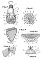
- FIGURE 1 is a perspective view of a drill bit embodying the present invention;
- FIGURE 2 is a plan view of the crown end of the drill bit of Figure 1;
- FIGURES 3 and 3A are perspective views of a slice of the bit illustrated in Figures 1 and 2;
- FIGURES 4 and 4A-4C are schematic views illustrating the orientation of the diamond inserts in the matrix of the bit;
- FIGURE 5 is a partial cross-sectional view of the bit of Figures 1 and 2;
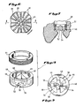
- FIGURE 6 is a plan view of the crown end of a second preferred embodiment of the present invention;
- FIGURE 7 is a partial cross-sectional view of the bit of Figure 6.
- FIGURE 8 is a perspective view of the center cutting element of the bit of Figures 6 and 7.
- FIGURE 9 is a bottom plan view of the element of Figure 8.
- FIGURE 10 is a cross-sectional view taken along line 10-10 of Figure 4A showing the grooving action of the diamond inserts of the present invention.
- FIGURE 11 is a plan view of a tool used to form a mold for casting the bit of the present invention.
- The present invention provides a novel design for a drill bit which utilizes cleaved, hemispherically shaped diamond cutting elements to provide a bit having increased penetration rates.
- Reference is now made to the drawings in which like parts are designated with like numerals throughout. Illustrated in Figures 1 and 2 is a
drill bit 10 of the type which may be constructed in accordance with the instant invention.Drill bit 10 comprises abody 12 formed of suitable material to withstand stress during operation. The upper portion of the body is provided with an exteriorly threadedneck 14 so that thebit 10 may be interconnected at the bottom of a drilling string. The lower body section orcrown 16 of thebit 10 is surfaced with ametal matrix 18 in which thediamond cutting elements 20 may be embedded. The matrix is a relatively hard, tough material such as bronze, or a similar metal alloy such as copper nickel alloy containing powdered tungsten carbide in quantities sufficient to convey the required strength and erosion resistance. Alternatively, the matrix may be composed of a suitably hard plastic material capable of being cast upon the bit and having the properties of resisting wear and retaining the cutting elements. The material is of a suitable thickness to provide the required strength, resistance to erosion and abrasion, and to embed the diamond cutting elements firmly therein. - In casting the matrix material upon the
bit body 12, it is common to provide recesses or a roughened surface on the bit body so that the matrix material will rigidly and firmly anchor to the bit body and form a permanent and fixed part of the drill bit. - In the embodiment illustrated in Figure 1, the matrix of the drill bit is shaped to have a generally semitoroidal end face defining an outer
cylindrical gauge face 22, a lower, generallycurved drilling face 24, and aninterior coring face 26. Theinterior face 26 opens into acentral passageway 28 extending through the bit body, and through which drilling fluid is directed down the drill string to the formation and across the face of the bit.Matrix 18 is formed such that it has a plurality offins 30 into which thediamond cutting elements 20 are embedded. - Fins 30 define a plurality of channels or
water courses 32 which extend outwardly from the central passageway in the interior face, across the drilling face and up the gauge face of the bit. Accordingly, drilling fluid delivered through the drill pipe throughpassageway 28 is distributed through these flow passageways orwater courses 32 to wash cuttings from the drilling area and upwardly to the top of the well as is well-known in the art. Additionally, in the embodiment illustrated, the matrix of the bit is provided with a series ofjunk slots 34 which are designed to discharge cuttings from the drilling area. It should be noted that a number of other configurations suitable for use on a diamond drilling bit would be obvious to those skilled in the art. - As can best be seen in Figure 5, a pair of hemispherically shaped
diamond cutting elements 33 are placed in aprojection 35 incentral passageway 28.Cutting elements 33 remove the core that is formed as drilling face 24 progresses through the formation. - Reference is next made to Figures 3, 3A, 4 and 4A-4C which illustrate the manner in which
diamond cutting elements 20 are embedded in thematrix 18 in accordance with the teachings of the present invention.Cutting elements 20 have a hemispherical shape and aplanar surface 38 formed by cleaving a diamond. In the preferred embodiment, cuttingelements 20 are obtained by cleaving a round diamond in half. - As can best be seen in Figure 4A and 4C,
diamond cutting elements 20 are embedded inmatrix 18 such that thecenter 21 of eachelement 20 is behindface 19 ofmatrix 18. Accordingly, slightly over half of each cuttingelement 20 is embedded within the matrix to ensure that the elements are securely fixed in place. -
Diamond cutting elements 20 are oriented withinmatrix 18 offins 30 to provide the optimum cutting surface. Generally, the rounded surface of cuttingelement 20 is oriented on thelowermost tip 31 offin 30. The orientation ofelements 20 can best be seen with reference to Figures 4 and 4A. - Illustrated in Figure 4 are lines X-X′, Y-Y′ and Z-Z′ which are oriented at 90 degrees to each other to define a three dimensional space and which intersect each other at
center 21 ofdiamond element 20. The plane defined by Lines Y-Y′ and Z-Z′ is parallel to face 19 offin 30 with line Y-Y′ passing through thecenter 21 ofdiamond element 20. It should be appreciated that while line Y-Y′ has been shown as a straight line for purposes of illustration in Figure 4A, it is parallel to face 19 offin 30 and will be a curved line whereface 19 is curved. Line X-X′ is perpendicular to face 19 offin 30. - The flat or
planar surface 38 which is defined by the cleaved face ofelement 20 is rotated in two directions with respect to the plane defined by lines X-X′ and Z-Z′. First, as shown in Figure 4B, leadingedge 40 ofelement 20 is inclined downward around the X-X′ axis at a first angle α as illustrated by line P-P′ to create a pitch. This permits cuttingelement 20 to groove down into the rock formations. Angle α can be increased or decreased depending upon the type of formation in which the bit will be used. Generally, angle α is within the range of 30-60 degrees. Preferably, angle α is about 45 degrees. - The
outer edge 44 ofdiamond cutting element 20 is also inclined downward around the P-P′ axis from a plane defined by lines X-X′ and P-P′ at a second angle β as illustrated by line W-W′ in Figure 4. This downward inclination exposes thesharp cutting edge 44 andplanar surface 38 of cuttingelement 20 to the formation being drilled. If angle β is formed before angle α, the rotation occurs around the Z-Z′ axis as illustrated on Figure 4C. Angle β can also be adjusted within a suitable range depending upon the size of the cutting element and the hardness of the formation in which bit 10 will be used. Generally, angle β is within the range of 15-30 degrees. Preferably, angle β is about 30 degrees. - As can be seen from the foregoing, lines P-P′ and W-W′ define the
planar surface 38 ofelement 20. This plane is rotated in two directions from the plane defined by lines X-X′ and Z-Z′ if angle β is created first. Otherwise, angle β is measured from the plane defined by lines X-X′ and P-P′. - As can be seen in Figures 3 and 3A, the orientation of the diamond cutting elements changes as they progress from the outer face to the interior face of
bit 10. The greatest change occurs adjacent lowermost tip 31 offin 30. - Reference is next made to Figures 6-9 which illustrate a second preferred embodiment of the present invention. In this embodiment,
fins 30 are substantially identical to the embodiment illustrated in Figures 1 and 2. Acore cutting insert 46 is provided at the center ofcentral passageway 28 to remove the core which is left as the formation is being drilled.Core cutting insert 46 is generally disk shaped withcrossbars 48 andopenings 49 formed in the center thereof.Insert 46 is positioned incentral passageway 28 and is secured in place by threadedring 51.Openings 49 permit drilling fluid to pass throughinsert 46 to clean and lubricate the face ofbit 10. The upper edges ofcrossbars 48 are tapered to create as little turbulence as possible as the fluid passes throughopenings 49. - A pair of
notches 50 are formed in the bottom ofinsert 46 to permit easy alignment ofinsert 46 withincentral passageway 28. Thenotches 50 also help prevent rotation ofinsert 46 withinbit 10. - A pair of
diamond cutting elements crossbars 48 for removing the core.Diamond cutting elements elements elements diamond cutting elements - Reference is next made to Figure 10 which illustrates the cutting and grooving action of
diamond cutting elements 20. Asplanar surface 38 of cuttingelement 20 engagesrock formation 60, it fractures and grooves the rock thus formingpieces 62 which are carried away by the drilling fluid. Agroove 64 is formed inrock formation 60 by the cutting action ofelement 20. - Figure 11 illustrates a
tool 66 which can be used in the formation of a mold for castingbit 10. Generally, diamond bits are formed by mounting the diamonds in a graphite mold which is then filled with a metal powder that is sintered to form the matrix which holds the diamonds.Tool 66 includes a hemispherically shapedbody 68 which is covered with a plurality of cuttingblades 70. Aring 72, also covered with cutting blades is formed adjacentplanar face 74 ofbody 68. -
Body 68 is mounted on ashaft 76 for attachment to a suitable mill.Tool 66 is rotated by the mill and cuts a portion of a hemispherically shaped hole in the graphite mold into whichdiamond cutting elements 20 can be mounted. Since the edge ofbody 68 adjacentplanar face 74 tends to wear first,ring 72 is provided to create a slightly larger opening adjacent the planar face. This ensures that the hole created bytool 66 is properly sized to receive thediamond cutting element 20, especially the sharp edge adjacent the cleaved face. - As can be seen from the foregoing, the present invention provides a novel drill bit design which uses hemispherically shaped diamond inserts having a cleaved face as cutting elements. The inserts are positioned in the matrix of the bit to expose a sharp cutting surface which knives through the formation being drilled to provide faster penetration rates than other types of diamond drilling bits.
- While the invention has been described with respect to the presently preferred embodiments, it will be appreciated that changes and modifications can be made without departing from the scope or essential characteristics of the invention. Accordingly, the scope of the invention is defined by the appended claims rather than by the foregoing description. All changes or modifications which come within the meaning and range of equivalency of the claims are to be embraced within their scope.
Claims (16)
a body portion including a matrix forming a face of said bit;
means to define fluid passageways across said matrix, said means dividing said matrix into a plurality of fins; and
a plurality of hemispherically shaped diamond cutting elements embedded in each of said fins, each element having a cleaved, planar face, a portion of the planar face of each of said cutting elements which is not embedded in each fin being disposed to define a cutting surface to successively drill the formation upon rotation of the bit.
a body portion including a matrix forming a face of said bit;
means to define fluid passageways across said matrix, said means dividing said matrix into a plurality of fins;
a plurality of hemispherically shaped diamond cutting elements each having a cleaved planar face, said elements being embedded in each of said fins such that a portion of the planar face of each element is exposed, the elements being positioned such that they have a leading edge in the direction of rotation of the bit and an outer edge distal from said matrix, wherein the leading edge is inclined downward at a first angle α from a plane normal to the face of the bit and parallel to the direction of rotation and wherein the outer edge is inclined downward at a second angle β from a plane normal to the face of the bit and parallel to the intersection of the planar face of the diamond element with the face of the bit.
Applications Claiming Priority (2)
| Application Number | Priority Date | Filing Date | Title |
|---|---|---|---|
| US208407 | 1988-06-17 | ||
| US07/208,407 US4858706A (en) | 1987-09-15 | 1988-06-17 | Diamond drill bit with hemispherically shaped diamond inserts |
Publications (2)
| Publication Number | Publication Date |
|---|---|
| EP0346924A2 true EP0346924A2 (en) | 1989-12-20 |
| EP0346924A3 EP0346924A3 (en) | 1991-05-08 |
Family
ID=22774503
Family Applications (1)
| Application Number | Title | Priority Date | Filing Date |
|---|---|---|---|
| EP19890110988 Withdrawn EP0346924A3 (en) | 1988-06-17 | 1989-06-16 | Diamond drill bit |
Country Status (3)
| Country | Link |
|---|---|
| US (1) | US4858706A (en) |
| EP (1) | EP0346924A3 (en) |
| CA (1) | CA1314281C (en) |
Cited By (1)
| Publication number | Priority date | Publication date | Assignee | Title |
|---|---|---|---|---|
| FR2915232A1 (en) * | 2007-04-23 | 2008-10-24 | Total Sa | TREPAN FOR DRILLING A WELL AND METHOD FOR DRESSING THE SAME. |
Families Citing this family (22)
| Publication number | Priority date | Publication date | Assignee | Title |
|---|---|---|---|---|
| US4989578A (en) * | 1989-08-30 | 1991-02-05 | Lebourg Maurice P | Method for forming diamond cutting elements for a diamond drill bit |
| US5056382A (en) * | 1990-12-20 | 1991-10-15 | Smith International, Inc. | Matrix diamond drag bit with PCD cylindrical cutters |
| US5158393A (en) * | 1991-01-22 | 1992-10-27 | Joseph Bossler | Industrial and roadway identification and floor surface treatment system, and diamond surface drill bit for use in installing the system |
| US5252009A (en) * | 1991-01-22 | 1993-10-12 | Joseph Bossler | Industrial and roadway identification and floor surface treatment system, and diamond surface drill bit for use in installing the system |
| US5279375A (en) * | 1992-03-04 | 1994-01-18 | Baker Hughes Incorporated | Multidirectional drill bit cutter |
| US5247923A (en) * | 1992-03-09 | 1993-09-28 | Lebourg Maurice P | Method of forming a diamond drill bit element using laser trimming |
| US5560440A (en) * | 1993-02-12 | 1996-10-01 | Baker Hughes Incorporated | Bit for subterranean drilling fabricated from separately-formed major components |
| BE1010802A3 (en) * | 1996-12-16 | 1999-02-02 | Dresser Ind | Drilling head. |
| US7571780B2 (en) * | 2006-03-24 | 2009-08-11 | Hall David R | Jack element for a drill bit |
| US8522897B2 (en) | 2005-11-21 | 2013-09-03 | Schlumberger Technology Corporation | Lead the bit rotary steerable tool |
| US8360174B2 (en) | 2006-03-23 | 2013-01-29 | Schlumberger Technology Corporation | Lead the bit rotary steerable tool |
| US7753144B2 (en) | 2005-11-21 | 2010-07-13 | Schlumberger Technology Corporation | Drill bit with a retained jack element |
| US20070192112A1 (en) * | 2006-02-10 | 2007-08-16 | Hall David R | A Method for Providing Pavement Degradation Equipment |
| US7954401B2 (en) | 2006-10-27 | 2011-06-07 | Schlumberger Technology Corporation | Method of assembling a drill bit with a jack element |
| US7721826B2 (en) | 2007-09-06 | 2010-05-25 | Schlumberger Technology Corporation | Downhole jack assembly sensor |
| US20090138242A1 (en) * | 2007-11-27 | 2009-05-28 | Schlumberger Technology Corporation | Minimizing stick-slip while drilling |
| US8261632B2 (en) | 2008-07-09 | 2012-09-11 | Baker Hughes Incorporated | Methods of forming earth-boring drill bits |
| CA2773336C (en) * | 2009-04-02 | 2017-08-22 | Newtech Drilling Products, Llc | Drill bit for earth boring |
| US8701799B2 (en) | 2009-04-29 | 2014-04-22 | Schlumberger Technology Corporation | Drill bit cutter pocket restitution |
| WO2011057303A2 (en) * | 2009-11-09 | 2011-05-12 | Newtech Drilling Products, Llc. | Drill bit with recessed center |
| US20150368976A1 (en) * | 2014-06-19 | 2015-12-24 | Tercel Ip Ltd | Fixed-cutter drill bits generating cores |
| WO2017106388A1 (en) | 2015-12-14 | 2017-06-22 | Smith International, Inc. | Direct casting of ultrahard insert in bit body |
Citations (4)
| Publication number | Priority date | Publication date | Assignee | Title |
|---|---|---|---|---|
| US3311181A (en) * | 1964-05-04 | 1967-03-28 | John B Fowler | Bi-metal drilling tooth |
| US3407445A (en) * | 1966-03-02 | 1968-10-29 | Gen Electric | High pressure reaction vessel for the preparation of diamond |
| US3537491A (en) * | 1968-09-12 | 1970-11-03 | Wallace Murray Corp | Cutting tools |
| US4492277A (en) * | 1983-02-22 | 1985-01-08 | Creighton Kenneth R | Hydraulic energy drill bit |
Family Cites Families (9)
| Publication number | Priority date | Publication date | Assignee | Title |
|---|---|---|---|---|
| US2199692A (en) * | 1937-08-11 | 1940-05-07 | Globe Oil Tools Co | Demountable blade bit |
| US3027952A (en) * | 1958-07-30 | 1962-04-03 | Socony Mobil Oil Co Inc | Drill bit |
| US3318399A (en) * | 1965-03-22 | 1967-05-09 | Exxon Production Research Co | Diamond bits and similar tools |
| US3997011A (en) * | 1975-05-27 | 1976-12-14 | Staroba Otto R | Button drill bit structure |
| US4109737A (en) * | 1976-06-24 | 1978-08-29 | General Electric Company | Rotary drill bit |
| US4254840A (en) * | 1978-10-05 | 1981-03-10 | Reed Tool Company | Drill bit insert |
| US4373593A (en) * | 1979-03-16 | 1983-02-15 | Christensen, Inc. | Drill bit |
| DE3113109C2 (en) * | 1981-04-01 | 1983-11-17 | Christensen, Inc., 84115 Salt Lake City, Utah | Rotary drill bit for deep drilling |
| US4716976A (en) * | 1986-10-28 | 1988-01-05 | Kennametal Inc. | Rotary percussion drill bit |
-
1988
- 1988-06-17 US US07/208,407 patent/US4858706A/en not_active Expired - Fee Related
-
1989
- 1989-06-16 EP EP19890110988 patent/EP0346924A3/en not_active Withdrawn
- 1989-06-16 CA CA000603100A patent/CA1314281C/en not_active Expired - Fee Related
Patent Citations (4)
| Publication number | Priority date | Publication date | Assignee | Title |
|---|---|---|---|---|
| US3311181A (en) * | 1964-05-04 | 1967-03-28 | John B Fowler | Bi-metal drilling tooth |
| US3407445A (en) * | 1966-03-02 | 1968-10-29 | Gen Electric | High pressure reaction vessel for the preparation of diamond |
| US3537491A (en) * | 1968-09-12 | 1970-11-03 | Wallace Murray Corp | Cutting tools |
| US4492277A (en) * | 1983-02-22 | 1985-01-08 | Creighton Kenneth R | Hydraulic energy drill bit |
Non-Patent Citations (1)
| Title |
|---|
| SOVIET INVENTIONS ILLUSTRATED Section P/Q,week 84/19,20 June 1984 Derwent Publications Ltd.,London,GB * |
Cited By (5)
| Publication number | Priority date | Publication date | Assignee | Title |
|---|---|---|---|---|
| FR2915232A1 (en) * | 2007-04-23 | 2008-10-24 | Total Sa | TREPAN FOR DRILLING A WELL AND METHOD FOR DRESSING THE SAME. |
| WO2008149240A2 (en) * | 2007-04-23 | 2008-12-11 | Total S.A. | Bit for drilling wells and associated drilling method |
| WO2008149240A3 (en) * | 2007-04-23 | 2009-02-12 | Total Sa | Bit for drilling wells and associated drilling method |
| RU2469173C2 (en) * | 2007-04-23 | 2012-12-10 | Тоталь С.А. | Well drilling bit, and drilling method |
| US8960335B2 (en) | 2007-04-23 | 2015-02-24 | Total S.A. | Bit for drilling wells and associated drilling method |
Also Published As
| Publication number | Publication date |
|---|---|
| US4858706A (en) | 1989-08-22 |
| EP0346924A3 (en) | 1991-05-08 |
| CA1314281C (en) | 1993-03-09 |
Similar Documents
| Publication | Publication Date | Title |
|---|---|---|
| US4858706A (en) | Diamond drill bit with hemispherically shaped diamond inserts | |
| US4940099A (en) | Cutting elements for roller cutter drill bits | |
| US4989578A (en) | Method for forming diamond cutting elements for a diamond drill bit | |
| US4719979A (en) | Expendable diamond drag bit | |
| US4352400A (en) | Drill bit | |
| US5176212A (en) | Combination drill bit | |
| CA2456501C (en) | Multi-lobed cutter element for drill bit | |
| US4602691A (en) | Diamond drill bit with varied cutting elements | |
| US7757789B2 (en) | Drill bit and insert having bladed interface between substrate and coating | |
| EP0554568B1 (en) | Mosaic diamond drag bit cutter having a nonuniform wear pattern | |
| US5443565A (en) | Drill bit with forward sweep cutting elements | |
| US6296069B1 (en) | Bladed drill bit with centrally distributed diamond cutters | |
| EP0117241B1 (en) | Drill bit and improved cutting element | |
| AU612454B2 (en) | Method and apparatus for establishing hydraulic flow regime in drill bits | |
| US5247923A (en) | Method of forming a diamond drill bit element using laser trimming | |
| EP0354164A2 (en) | Blade drill bit and method for its construction | |
| EA027355B1 (en) | Kerfing hybrid drill bit | |
| US6932172B2 (en) | Rotary contact structures and cutting elements | |
| JPS6144193B2 (en) | ||
| USRE33757E (en) | Diamond drill bit with varied cutting elements | |
| EP0643194B1 (en) | Asymmetrical PDC cutter for a drilling bit | |
| CA1335812C (en) | Excavating tooth for an earth auger | |
| CN112983286B (en) | Cutting tooth and drill bit with same | |
| US20040231894A1 (en) | Rotary tools or bits | |
| EP0236924A2 (en) | Diamond setting in a cutting tooth in a drill bit with an increased effective diamond width |
Legal Events
| Date | Code | Title | Description |
|---|---|---|---|
| PUAI | Public reference made under article 153(3) epc to a published international application that has entered the european phase |
Free format text: ORIGINAL CODE: 0009012 |
|
| AK | Designated contracting states |
Kind code of ref document: A2 Designated state(s): AT BE DE ES FR GB GR IT NL SE |
|
| PUAL | Search report despatched |
Free format text: ORIGINAL CODE: 0009013 |
|
| AK | Designated contracting states |
Kind code of ref document: A3 Designated state(s): AT BE DE ES FR GB GR IT NL SE |
|
| 17P | Request for examination filed |
Effective date: 19911108 |
|
| 17Q | First examination report despatched |
Effective date: 19921103 |
|
| STAA | Information on the status of an ep patent application or granted ep patent |
Free format text: STATUS: THE APPLICATION IS DEEMED TO BE WITHDRAWN |
|
| 18D | Application deemed to be withdrawn |
Effective date: 19940309 |