EP0347743A2 - Septum for implantable devices releasing agents - Google Patents
Septum for implantable devices releasing agents Download PDFInfo
- Publication number
- EP0347743A2 EP0347743A2 EP89110846A EP89110846A EP0347743A2 EP 0347743 A2 EP0347743 A2 EP 0347743A2 EP 89110846 A EP89110846 A EP 89110846A EP 89110846 A EP89110846 A EP 89110846A EP 0347743 A2 EP0347743 A2 EP 0347743A2
- Authority
- EP
- European Patent Office
- Prior art keywords
- septum
- chamber
- substance
- opening
- dispensing
- Prior art date
- Legal status (The legal status is an assumption and is not a legal conclusion. Google has not performed a legal analysis and makes no representation as to the accuracy of the status listed.)
- Granted
Links
Images

Classifications
-
- A—HUMAN NECESSITIES
- A61—MEDICAL OR VETERINARY SCIENCE; HYGIENE
- A61M—DEVICES FOR INTRODUCING MEDIA INTO, OR ONTO, THE BODY; DEVICES FOR TRANSDUCING BODY MEDIA OR FOR TAKING MEDIA FROM THE BODY; DEVICES FOR PRODUCING OR ENDING SLEEP OR STUPOR
- A61M5/00—Devices for bringing media into the body in a subcutaneous, intra-vascular or intramuscular way; Accessories therefor, e.g. filling or cleaning devices, arm-rests
- A61M5/14—Infusion devices, e.g. infusing by gravity; Blood infusion; Accessories therefor
- A61M5/142—Pressure infusion, e.g. using pumps
- A61M5/14244—Pressure infusion, e.g. using pumps adapted to be carried by the patient, e.g. portable on the body
- A61M5/14276—Pressure infusion, e.g. using pumps adapted to be carried by the patient, e.g. portable on the body specially adapted for implantation
-
- A—HUMAN NECESSITIES
- A61—MEDICAL OR VETERINARY SCIENCE; HYGIENE
- A61M—DEVICES FOR INTRODUCING MEDIA INTO, OR ONTO, THE BODY; DEVICES FOR TRANSDUCING BODY MEDIA OR FOR TAKING MEDIA FROM THE BODY; DEVICES FOR PRODUCING OR ENDING SLEEP OR STUPOR
- A61M39/00—Tubes, tube connectors, tube couplings, valves, access sites or the like, specially adapted for medical use
- A61M39/02—Access sites
- A61M39/0208—Subcutaneous access sites for injecting or removing fluids
- A61M2039/0238—Subcutaneous access sites for injecting or removing fluids having means for locating the implanted device to insure proper injection, e.g. radio-emitter, protuberances, radio-opaque markers
-
- Y—GENERAL TAGGING OF NEW TECHNOLOGICAL DEVELOPMENTS; GENERAL TAGGING OF CROSS-SECTIONAL TECHNOLOGIES SPANNING OVER SEVERAL SECTIONS OF THE IPC; TECHNICAL SUBJECTS COVERED BY FORMER USPC CROSS-REFERENCE ART COLLECTIONS [XRACs] AND DIGESTS
- Y10—TECHNICAL SUBJECTS COVERED BY FORMER USPC
- Y10S—TECHNICAL SUBJECTS COVERED BY FORMER USPC CROSS-REFERENCE ART COLLECTIONS [XRACs] AND DIGESTS
- Y10S128/00—Surgery
- Y10S128/12—Pressure infusion
Definitions
- the invention relates to a septum for implantable drug delivery devices, e.g. Medications, to the patient's body, the septum being tightly inserted as a cover for a medication chamber into the associated opening through one or more clamping members.
- implantable drug delivery devices e.g. Medications
- the invention has for its object to provide a septum of the type mentioned, in which a larger area is available for piercing, without changing the free span of the septum.
- this object is achieved in that the septum is annular, the part of the device wall located within the septum being firmly connected to the rest of the housing. This ensures that a much larger area is available for inserting the injection needle, so that the septum is not so stressed by the injection needle punctures. Due to the design according to the invention, the device for delivering active substances is somewhat larger in diameter, but this disadvantage is largely eliminated by the considerably longer shelf life of the septum.
- the septum according to the invention is suitable for implantable devices for the metered delivery of a substance, for example medication, the device having two chambers separated from one another by a flexible membrane of which one chamber containing the substance to be dispensed is provided with a dispensing opening connected to a dispensing catheter and a refill opening, and the other chamber is filled with a propellant which isobarically expands to dispense the substance to be dispensed under evaporation.
- the septum according to the invention can be used to seal the chamber which contains the substance to be dispensed. It can also be achieved that the refilling of the chamber can be carried out much more often without the septum becoming leaky.
- the septum according to the application is also advantageous on an implantable device for the metered delivery of a substance, for example medication, in which the device has two chambers separated from one another by a flexible membrane, one of which contains the substance to be dispensed with one with a dispensing opening connected to a dispensing catheter and a refilling opening is provided, and the other chamber is filled with a propellant which isobarically expands to dispense the substance to be dispensed under evaporation, a device for additional dispensing of medication or between the dispensing opening of the chamber and the dispensing catheter is provided in the outlet catheter.
- the annular septum can serve to seal the chamber for the additional introduction of medicaments, the septum being arranged around the refill opening.
- the septum can be found more easily.
- This finding of the annular chamber can also be made considerably easier by a template which is placed on the patient's skin, the position of the template being determined, for example, by the palpable edge of the implanted device.
- the refill opening can be provided centrally on the device and the annular septum can be arranged concentrically to the refill opening.
- the template can also be placed on the implanted device in order to find the annular septum in such a way that the center of the template coincides with the central, outwardly projecting refill opening.
- the template then has a continuous opening at a distance from the center corresponding to the radius of the annular chamber, which defines the location of the annular chamber. If the position of the template is determined by the palpable edge of the implanted device, then the refill opening must be arranged exactly in the center of the device. The edge of the template could also be used to determine the location of the annular chamber if its diameter corresponds to that of the annular chamber.
- Such implantable devices for the metered delivery of a substance usually serve to introduce insulin or other long-term medication directly into the body, these devices being refilled by means of an injection syringe via the refill openings, which are closed by a septum.
- an injection syringe via the refill openings, which are closed by a septum.
- this chamber is provided on the outer periphery of the device and, like the refill opening, is closed with a circular septum, through which the additional injection of the medication is made possible by means of an injection needle.
- This known embodiment has the disadvantage that the doctor who injects the additional medication first has to search for this additional opening of the chamber, which is closed with a septum, which is not very easy with an implanted device.
- the site for the additional introduction of the drug is very often pierced by the injection needle, which can then lead to leaks in the septum. All of these disadvantages are avoided by the inventive design described above.
- the device has a housing composed of two parts 1, 2, the interior of which is divided into two chambers 4, 5 by a flexible membrane 3.
- the chamber 4 is intended to receive the medication to be dispensed, the chamber 5 containing a propellant which isobarly expands due to the body heat.
- the expansion of the propellant acts on the membrane 3 in the sense of displacing the medicament from the chamber 4, the medicament being dispensed into the patient's body via the outlet opening 6, an outlet reducing device 7 and an outlet catheter 8.
- the outlet catheter 8 Before the medication reaches the outlet catheter 8, it is introduced into a chamber 9, which is provided in a ring on part 1 of the housing.
- This chamber 9 is closed on its upper side by a ring 10, which can be pierced by an injection needle and automatically seals again after the injection needle has been pulled out, that is to say by a septum.
- This ring 10 is held in place by an annular fastening device 11.
- the chamber 4 can be refilled via a further septum 12, which is held in place by means of a fastening part 13.
- the implantable device is designed as a rotating body, the refill opening 12 being arranged centrally in the device and the annular chamber 9 being arranged concentrically thereto.
- a template (not shown) can be placed on the patient's skin in such a way that the center of the template coincides with the refill opening.
- the template has a hole at a distance from the center corresponding to the radius of the annular chamber, which hole is then located above the annular chamber after the template has been placed accordingly, so that when the injection needle is inserted through the hole, the annular chamber is reliably found.
- the outlet reducing device 7 is formed in the present case by a hose turn which is wound several times in a recess in part 1 of the housing. These The recess is sealed by a cover 14 so that a smooth outer contour of the implantable device is achieved.
- the chamber 9 and thus the sealing ring 10 are arranged concentrically around the refill opening 12.
- the implanted device continuously delivers the medication in the chamber 4 to the patient's body via the outlet catheter 8. If more of this medication or another additional medication is now to be dispensed to the patient's body for health reasons, then the ring 10 is pierced by means of an injection syringe, which is pointed at the puncture site by the attached template, and the medication to be dispensed into the chamber 9 injected, from which it is delivered directly to the body via the outlet catheter 8.
- the flow resistance in the outlet reducing device 7 is so great that the medication is prevented from being pushed back into the chamber 4 of the implantable device. It does not necessarily have to be the same medication that is dispensed via the chamber 4, but it can e.g. heparin or a similar substance can also be injected to clear the catheter.
- annular chamber 21 is provided in a housing 20, which is open at the top, that is to say in the direction of the end face of the housing 20. There, the chamber 21 is closed by means of an annular septum 22, which is fixed in the housing 20 by means of annular clamping members 23, 24.
- the supply line for a permanent medication is designated with 25 and with 26 delivery catheter.
- a disk-shaped housing which consists of two parts, namely the bottom 30 and an upper part 31.
- a circular opening is provided, in which a central piece 32 is inserted centrally, which is fixed on the upper part via arms 33, 34, 35.
- An annular space is left between the upper part 31 and the middle piece 32, which is closed off by an equally annular septum 36.
- the annular septum 36 is again fastened with annular clamping members 37, 38 to the upper part or to the middle piece.
- the middle piece 32 has a smaller thickness than the upper part 31 is high, so that in the interior of the housing Chamber is left in which the injected drug is located.
- the supply line is designated with 39 and the outlet catheter with 40.
- the shape of the chamber is not critical and can be selected according to the purpose.
- FIGS. 3 to 5 are mere injection sites for medication, whereas the embodiment according to FIGS. 1 and 2 is a device for the metered continuous dispensing of medications, which additionally has a device for injecting medications. All the embodiments have in common that the septum or one of the septa is annular, which achieves the advantages set out above.
- the design according to the invention can also serve as a mere injection point for medications which are to be brought to special organs, the hollow organ in this regard, such as e.g. the vein to be brought in is difficult or impossible to access.
- the leads 25 and 39 are then omitted, so that only the outlet catheter 26 or 40 leads away from the implanted device.
Landscapes
- Health & Medical Sciences (AREA)
- Hematology (AREA)
- Engineering & Computer Science (AREA)
- Anesthesiology (AREA)
- Biomedical Technology (AREA)
- Heart & Thoracic Surgery (AREA)
- Vascular Medicine (AREA)
- Life Sciences & Earth Sciences (AREA)
- Animal Behavior & Ethology (AREA)
- General Health & Medical Sciences (AREA)
- Public Health (AREA)
- Veterinary Medicine (AREA)
- Media Introduction/Drainage Providing Device (AREA)
- Infusion, Injection, And Reservoir Apparatuses (AREA)
Abstract
Septum für implantierbare Vorrichtungen zur Abgabe von Wirkstoffen, z.B. Medikamenten, an den Körper des Patienten, wobei das Septum als Abdeckung einer Medikamentkammer in die zugehörige Öffnung durch ein oder mehrere Klemmorgane dicht eingesetzt ist, wobei das Septum (22; 36; 10) ringförmig ausgebildet ist, und wobei der innerhalb des Septums befindliche Teil (32) der Vorrichtungswandung mit dem übrigen Gehäuse (31) fest verbunden ist.Septum for implantable drug delivery devices, e.g. Medications, on the patient's body, wherein the septum as a cover of a medication chamber is inserted tightly into the associated opening by one or more clamping members, the septum (22; 36; 10) being annular and the part located within the septum (32) of the device wall with the rest of the housing (31) is firmly connected.
Description
Die Erfindung bezieht sich auf ein Septum für implantierbare Vorrichtungen zur Abgabe von Wirkstoffen, z.B. Medikamenten, an den Körper des Patienten, wobei das Septum als Abdeckung einer Medikamentenkammer in die zugehörige Öffnung durch ein oder mehrere Klemmorgane dicht eingesetzt ist.The invention relates to a septum for implantable drug delivery devices, e.g. Medications, to the patient's body, the septum being tightly inserted as a cover for a medication chamber into the associated opening through one or more clamping members.
Bei bekannten Ausbildungen dieser Art ist bisher ein kreisrundes Septum verwendet worden, das am Rand durch Klemmorgane in der Vorrichtung gehalten ist. Der Mittelbereich des Septums hat die Öffnung der Medikamentenkammer frei überspannt, so daß der Größe des Septums durch die Spannweite insofern Grenzen gesetzt sind, als das Septum ein sehr elastischer, gummiartiger Körper ist, der sich nach jedem Einstich einer Injektionsnadel wieder dicht verschließen muß, wodurch bei zu großer Spannweite das Septum beim Einstechen am Boden der Kammer zur Anlage kommt, wodurch das Nachfüllen der Kammer erheblich behindert wird. Aufgrund der bei den bekannten Ausbildungen nur kleinen zur Verfügung stehenden Fläche zum Einstechen mittels der Injektionsnadel wird jede Einstichstelle sehr oft durch die Injektionsnadel benützt, so daß die bisherigen Septen bald zum Undichtwerden neigen.In known designs of this type, a circular septum has been used so far, which is held on the edge by clamping members in the device. The middle area of the septum has spanned the opening of the medication chamber freely, so that the size of the septum is limited by the span, insofar as the septum is a very elastic, rubber-like body that has to close tightly after each injection needle injection, which means that if the span is too large, the septum comes into contact with the piercing at the bottom of the chamber, which considerably hinders the refilling of the chamber. Due to the small area available for piercing by means of the injection needle in the known designs, each puncture site is very often used by the injection needle, so that the previous septa soon tend to leak.
Der Erfindung liegt die Aufgabe zugrunde, ein Septum der eingangs genannten Art zu schaffen, bei welchem eine größere Fläche zum Einstechen zur Verfügung steht, ohne daß die freie Spannweite des Septums verändert wird.The invention has for its object to provide a septum of the type mentioned, in which a larger area is available for piercing, without changing the free span of the septum.
Erfindungsgemäß wird diese Aufgabe dadurch gelöst, daß das Septum ringförmig ausgebildet ist, wobei der innerhalb des Septums befindliche Teil der Vorrichtungswandung mit dem übrigen Gehäuse fest verbunden ist. Dadurch wird erreicht, daß eine wesentlich größere Fläche für das Einstechen der Injektionsnadel zur Verfügung steht, so daß das Septum durch die Einstiche der Injektionsnadel nicht so beansprucht wird. Durch die erfindungsgemäße Ausbildung wird zwar die Vorrichtung zur Abgabe von Wirkstoffen durchmessermäßig etwas größer, jedoch ist dieser Nachteil durch die wesentlich längere Haltbarkeit des Septums bei weitem aufgehoben.According to the invention, this object is achieved in that the septum is annular, the part of the device wall located within the septum being firmly connected to the rest of the housing. This ensures that a much larger area is available for inserting the injection needle, so that the septum is not so stressed by the injection needle punctures. Due to the design according to the invention, the device for delivering active substances is somewhat larger in diameter, but this disadvantage is largely eliminated by the considerably longer shelf life of the septum.
In besonders vorteilhafter Weise eignet sich das erfindungsgemäße Septum für implantierbare Vorrichtungen zur dosierten Abgabe eines Stoffes, z.B. Medikaments, wobei die Vorrichtung zwei voneinander durch eine flexible Membran getrennte Kammern aufweist, von welchen die eine Kammer, die den abzugebenden Stoff enthält, mit einer mit einem Ausgabekatheter verbundenen Ausgabeöffnung und einer Nachfüllöffnung versehen ist, und die andere Kammer mit einem Treibmittel gefüllt ist, das sich zur Ausgabe des abzugebenden Stoffes unter Verdampfung isobar ausdehnt. Bei einer solchen Ausbildung kann das erfindungsgemäße Septum zur Abdichtung der Kammer, die den abzugebenden Stoff enthält, dienen. Auch dadurch kann erreicht werden, daß die Nachfüllung der Kammer wesentlich öfter durchgeführt werden kann, ohne daß das Septum undicht wird.In a particularly advantageous manner, the septum according to the invention is suitable for implantable devices for the metered delivery of a substance, for example medication, the device having two chambers separated from one another by a flexible membrane of which one chamber containing the substance to be dispensed is provided with a dispensing opening connected to a dispensing catheter and a refill opening, and the other chamber is filled with a propellant which isobarically expands to dispense the substance to be dispensed under evaporation. With such a design, the septum according to the invention can be used to seal the chamber which contains the substance to be dispensed. It can also be achieved that the refilling of the chamber can be carried out much more often without the septum becoming leaky.
Weiters ist das anmeldungsgemäße Septum auch an einer implantierbaren Vorrichtung zur dosierten Abgabe eines Stoffes, z.B. Medikaments, vorteilhaft, bei welcher die Vorrichtung zwei voneinander durch eine flexible Membran getrennte Kammern aufweist, von welchen die eine Kammer, die den abzugebenden Stoff enthält, mit einer mit einem Ausgabekatheter verbundenen Ausgabeöffnung und einer Nachfüllöffnung versehen ist, und die andere Kammer mit einem Treibmittel gefüllt ist, das sich zur Ausgabe des abzugebenden Stoffes unter Verdampfung isobar ausdehnt, wobei zwischen der Ausgabeöffnung der Kammer und dem Ausgabekatheter eine Einrichtung für ein zusätzliches Eingeben von Medikamenten od. dgl. in den Auslaßkatheter vorgesehen ist. Bei einer solchen Vorrichtung kann das ringförmige Septum zur Abdichtung der Kammer für das zusätzliche Eingeben von Medikamenten dienen, wobei das Septum um die Nachfüllöffnung herum angeordnet ist. Dadurch ist neben der Vergrößerung der Oberfläche, die von der Injektionsnadel zu durchdringen ist, erreicht, daß das Septum leichter aufgefunden werden kann. Dieses Auffinden der ringförmigen Kammer kann überdies auch noch durch eine Schablone wesentlich erleichtert werden, die auf die Haut des Patienten gelegt wird, wobei die Lage der Schablone etwa durch den tastbaren Rand der implantierten Vorrichtung bestimmt wird. Schließlich kann die Nachfüllöffnung zentrisch an der Vorrichtung vorgesehen und das ringförmige Septum konzentrisch zur Nachfüllöffnung angeordnet sein. Dadurch kann zum Auffinden des ringförmigen Septums die Schablone auch so auf der implantierten Vorrichtung aufgesetzt werden, daß das Zentrum der Schablone mit der zentralen, nach außen vorspringenden Nachfüllöffnung übereinstimmt. Die Schablone besitzt dann in einer dem Radius der ringförmigen Kammer entsprechenden Entfernung vom Zentrum eine durchgehende öffnung, welche den Ort der ringförmigen Kammer anzeigt. Wenn die Lage der Schablone durch den tastbaren Rand der implantierten Vorrichtung bestimmt wird, dann muß die Nachfüllöffnung genau zentrisch in der Vorrichtung angeordnet sein. Zur Bestimmung des Ortes der ringförmigen Kammer könnte auch der Rand der Schablone dienen, wenn deren Durchmesser jenem der ringförmigen Kammer entspricht.Furthermore, the septum according to the application is also advantageous on an implantable device for the metered delivery of a substance, for example medication, in which the device has two chambers separated from one another by a flexible membrane, one of which contains the substance to be dispensed with one with a dispensing opening connected to a dispensing catheter and a refilling opening is provided, and the other chamber is filled with a propellant which isobarically expands to dispense the substance to be dispensed under evaporation, a device for additional dispensing of medication or between the dispensing opening of the chamber and the dispensing catheter is provided in the outlet catheter. In such a device, the annular septum can serve to seal the chamber for the additional introduction of medicaments, the septum being arranged around the refill opening. As a result, in addition to the increase in the surface area to be penetrated by the injection needle, the septum can be found more easily. This finding of the annular chamber can also be made considerably easier by a template which is placed on the patient's skin, the position of the template being determined, for example, by the palpable edge of the implanted device. Finally, the refill opening can be provided centrally on the device and the annular septum can be arranged concentrically to the refill opening. As a result, the template can also be placed on the implanted device in order to find the annular septum in such a way that the center of the template coincides with the central, outwardly projecting refill opening. The template then has a continuous opening at a distance from the center corresponding to the radius of the annular chamber, which defines the location of the annular chamber. If the position of the template is determined by the palpable edge of the implanted device, then the refill opening must be arranged exactly in the center of the device. The edge of the template could also be used to determine the location of the annular chamber if its diameter corresponds to that of the annular chamber.
Derartige implantierbare Vorrichtungen zur dosierten Abgabe eines Stoffes dienen üblicherweise dazu, Insulin oder sonstige Dauermedikamente in den Körper direkt einzubringen, wobei diese Vorrichtungen über die Nachfüllöffnungen, welche durch ein Septum abgeschlossen sind, mittels einer Injektionsspritze nachgefüllt werden. Nun ist es aber vielfach erforderlich, daß zu der kontinuierlichen Dosierung des Medikaments auch zusätzliches Medikament gegeben werden muß. Dazu ist es bereits bekannt, eine zusätzliche Kammer vorzusehen, welche mit dem Auslaßkatheter in Verbindung steht, und über welche zusätzliches Medikament direkt in den Auslaßkatheter eingespritzt werden kann. Diese Kammer ist bei der bekannten Ausführung an der Außenperipherie der Vorrichtung vorgesehen, und ebenso wie die Nachfüllöffnung mit einem kreisrunden Septum abgeschlossen, durch welches hindurch mittels einer Injektionsnadel das zusätzliche Einspritzen des Medikaments ermöglicht ist. Diese bekannte Ausführung hat den Nachteil, daß der Arzt, der das zusätzliche Medikament einspritzt, diese zusätzlich mit einem Septum verschlossene Öffnung der Kammer erst suchen muß, was bei einer implantierten Vorrichtung nicht ganz einfach ist. Außerdem wird die Stelle zur zusätzlichen Einführung des Medikaments von der Injektionsnadel sehr oft durchstochen, was dann in der Folge zu Undichtheiten des Septums führen kann. All diese genannten Nachteile werden durch die vorstehend beschriebene erfindungsgemäße Ausbildung vermieden.Such implantable devices for the metered delivery of a substance usually serve to introduce insulin or other long-term medication directly into the body, these devices being refilled by means of an injection syringe via the refill openings, which are closed by a septum. Now, however, it is often necessary to add additional medication to the continuous dosage of the medication. For this purpose, it is already known to provide an additional chamber which is connected to the outlet catheter and via which additional medicament can be injected directly into the outlet catheter. In the known embodiment, this chamber is provided on the outer periphery of the device and, like the refill opening, is closed with a circular septum, through which the additional injection of the medication is made possible by means of an injection needle. This known embodiment has the disadvantage that the doctor who injects the additional medication first has to search for this additional opening of the chamber, which is closed with a septum, which is not very easy with an implanted device. In addition, the site for the additional introduction of the drug is very often pierced by the injection needle, which can then lead to leaks in the septum. All of these disadvantages are avoided by the inventive design described above.
In der Zeichnung sind einige Ausführungsbeispiele des Erfindungsgegenstandes dargestellt.
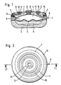
- Fig. 1 zeigt einen Vertikalschnitt durch eine mit einem erfindungsgemäßen Septum versehene Vorrichtung zur dosierten Abgabe eines Medikaments, und zwar nach Linie I-I der Fig. 2.
- Fig. 2 veranschaulicht eine Draufsicht auf die erfindungsgemäße Vorrichtung gemäß
Anspruch 1. - Fig. 3 zeigt einen Vertikalschnitt durch eine mit dem erfindungsgemäßen Septum versehene Zuspritzeinrichtung für ein Medikament.
- Fig. 4 zeigt einen Schnitt nach Linie IV-IV der Fig. 5 einer anderen Ausführungsform einer Zuspritzeinrichtung, welche gleichfalls mit dem erfindungsgemäßen Septum versehen ist.
- Fig. 5 zeigt einen Schnitt nach Linie V-V der Fig. 4.
- 1 shows a vertical section through a device provided with a septum according to the invention for the metered delivery of a medicament, specifically along line II of FIG. 2.
- 2 illustrates a top view of the device according to the invention according to
claim 1. - 3 shows a vertical section through an injection device for a medicament provided with the septum according to the invention.
- Fig. 4 shows a section along line IV-IV of Fig. 5 of another embodiment of an injection device, which is also provided with the septum according to the invention.
- FIG. 5 shows a section along line VV of FIG. 4.
Die Vorrichtung weist ein aus zwei Teilen 1, 2 zusammengesetztes Gehäuse auf, dessen Innenraum durch eine flexible Membran 3 in zwei Kammern 4, 5 geteilt ist. Die Kammer 4 ist dabei zur Aufnahme des abzugebenden Medikaments bestimmt, wobei die Kammer 5 ein Treibmittel enthält, welches sich durch die Körperwärme isobar ausdehnt. Durch das Ausdehnen des Treibmittels wird die Membran 3 im Sinne einer Verdrängung des Medikaments aus der Kammer 4 beaufschlagt, wobei das Medikament über die Auslaßöffnung 6, eine Auslaßreduziereinrichtung 7 und einen Auslaßkatheter 8 in den Körper des Patienten abgegeben wird. Bevor das Medikament den Auslaßkatheter 8 erreicht, wird es in eine Kammer 9 eingeleitet, welche ringförmig am dem Teil 1 des Gehäuses vorgesehen ist. Diese Kammer 9 ist an ihrer Oberseite durch einen Ring 10, welcher von einer Injektionsnadel durchstochen werden kann und sich nach Herausziehen der Injektionsnadel selbsttätig wieder abdichtet, also durch ein Septum, abgeschlossen. Dieser Ring 10 wird über eine ringförmige Befestigungseinrichtung 11 in seiner Lage festgehalten. Die Kammer 4 ist über ein weiteres Septum 12, welches mittels eines Befestigungsteiles 13 festgehalten ist, nachfüllbar.The device has a housing composed of two
Vorliegend ist die implantierbare Vorrichtung als Rotationskörper ausgebildet, wobei die Nachfüllöffnung 12 in der Vorrichtung zentrisch und die ringförmige Kammer 9 konzentrisch dazu angeordnet ist. Zur Auffindung der ringförmigen Kammer 9 ist eine - nicht dargestellte - Schablone so auf die Haut des Patienten auflegbar, daß das Zentrum der Schablone mit der Nachfüllöffnung übereinstimmt. Die Schablone besitzt in einem, dem Radius der ringförmigen Kammer entsprechenden Abstand vom Zentrum ein Loch, welches sich dann nach entsprechendem Auflegen der Schablone über der ringförmigen Kammer befindet, so daß bei Einstechen der Injektionsnadel durch das Loch hindurch zuverlässig die ringförmige Kammer aufgefunden wird.In the present case, the implantable device is designed as a rotating body, the refill opening 12 being arranged centrally in the device and the
Die Auslaßreduziereinrichtung 7 ist im vorliegenden Fall durch eine Schlauchwindung gebildet, welche mehrfach in einer Ausnehmung des Teiles 1 des Gehäuses herumgewunden ist. Diese Ausnehmung ist durch einen Deckel 14 so abgedichtet, daß eine glatte äußere Kontur der implantierbaren Vorrichtung erzielt ist.The outlet reducing device 7 is formed in the present case by a hose turn which is wound several times in a recess in
Wie aus Fig. 2 hervorgeht, ist die Kammer 9 und damit der Abdichtring 10 konzentrisch um die Nachfüllöffnung 12 herum angeordnet.As can be seen from FIG. 2, the
Das implantierte Gerät gibt über den Auslaßkatheter 8 kontinuierlich das in der Kammer 4 befindliche Medikament an den Körper des Patienten ab. Soll nun aus gesundheitlichen Gründen mehr von diesem Medikament oder ein anderes zusätzliches Medikament an den Körper des Patienten abgegeben werden, dann wird mittels einer Injektionsspritze, der der Einstichort von der aufgesetzten Schablone gewiesen wird, der Ring 10 durchstochen und das abzugebenden Medikament in die Kammer 9 injiziert, von welcher es unmittelbar über den Auslaßkatheter 8 an den Körper abgegeben wird. Der Flußwiderstand in der Auslaßreduziereinrichtung 7 ist dabei so groß, daß ein Zurückdrängen des Medikaments in die Kammer 4 der implantierbaren Vorrichtung verhindert ist. Es muß sich dabei nicht unbedingt um dasselbe Medikament handeln, das über die Kammer 4 ausgegeben wird, sondern es kann z.B. auch zur Freimachung des Katheters 8 Heparin oder eine ähnliche Substanz eingespritzt werden.The implanted device continuously delivers the medication in the
Beim Ausführungsbeispiel nach Fig. 3 ist in einem Gehäuse 20 eine ringförmige Kammer 21 vorgesehen, welche nach oben, also in Richtung zur Stirnfläche des Gehäuses 20 offen ist. Dort ist die Kammer 21 mittels eines ringförmigen Septums 22 abgeschlossen, welches mittels ringförmiger Klemmorgane 23, 24 im Gehäuse 20 festgelegt ist. Mit 25 ist die Zuleitung für eine Dauermedikament und mit 26 Abgabekatheter bezeichnet.In the exemplary embodiment according to FIG. 3, an
Bei der Ausführungsform gemäß Fig. 4 ist gleichfalls ein scheibenförmiges Gehäuse vorgesehen, welches aus zwei Teilen besteht, nämlich aus dem Boden 30 und einem Oberteil 31. In diesem Oberteil 31 ist eine kreisförmige Öffnung vorgesehen, in welche zentral ein Mittelstück 32 eingesetzt ist, welches über Arme 33, 34, 35 am Oberteil festgelegt ist. Zwischen dem Oberteil 31 und dem Mittelstück 32 ist ein ringförmiger Raum freigelassen, welcher über ein gleichfalls ringförmiges Septum 36 abgeschlossen ist. Das ringförmige Septum 36 ist wieder mit ringförmigen Klemmorganen 37, 38 an dem Oberteil bzw. am Mittelstück befestigt. Das Mittelstück 32 weist dabei geringere Dicke auf als der Oberteil 31 hoch ist, so daß im Inneren des Gehäuses eine Kammer freigelassen ist, in welcher sich das eingespritzte Medikament befindet. Mit 39 ist die Zuleitung und mit 40 der Auslaßkatheter bezeichnet. Die Form der Kammer ist dabei unkritisch und kann entsprechend dem Einsatzzweck gewählt werden.In the embodiment according to FIG. 4, a disk-shaped housing is also provided, which consists of two parts, namely the
Bei den Ausführungsformen gemäß Fig. 3 bis 5 handelt es sich um bloße Zuspritzstellen von Medikament, wogegen die Ausführungsform nach Fig. 1 und 2 eine Vorrichtung zur dosierten Dauerabgabe von Medikamenten ist, welche zusätzlich eine Einrichtung zur Zuspritzung von Medikamenten aufweist. All den Ausführungsformen ist gemeinsam, daß das Septum bzw. eines der Septen ringförmig ausgebildet ist, wodurch die vorstehend dargelegten Vorteile erzielt werden.The embodiments according to FIGS. 3 to 5 are mere injection sites for medication, whereas the embodiment according to FIGS. 1 and 2 is a device for the metered continuous dispensing of medications, which additionally has a device for injecting medications. All the embodiments have in common that the septum or one of the septa is annular, which achieves the advantages set out above.
In Abwandlung der in den Fig. 3 bis 5 dargestellten Ausbildungen, welche als Zusatz zu einer Infusionspumpe einsetzbar sind, kann die erfindungsgemäße Ausbildung auch als bloße Einspritzstelle für Medikamente dienen, die zu speziellen Organen zu bringen sind, wobei das diesbezügliche Hohlorgan, wie z.B. die zubringende Vene, nicht oder nur sehr schwer zugänglich ist. In diesem Fall entfallen dann die Zuleitungen 25 bzw. 39, so daß von der implantierten Einrichtung lediglich der Auslaßkatheter 26 bzw. 40 wegführt.3 to 5, which can be used as an additive to an infusion pump, the design according to the invention can also serve as a mere injection point for medications which are to be brought to special organs, the hollow organ in this regard, such as e.g. the vein to be brought in is difficult or impossible to access. In this case, the
Claims (4)
Applications Claiming Priority (2)
| Application Number | Priority Date | Filing Date | Title |
|---|---|---|---|
| AT0163188A AT391416B (en) | 1988-06-23 | 1988-06-23 | SEPTUM FOR IMPLANTABLE DEVICES FOR DELIVERING ACTIVE SUBSTANCES |
| AT1631/88 | 1988-06-23 |
Publications (3)
| Publication Number | Publication Date |
|---|---|
| EP0347743A2 true EP0347743A2 (en) | 1989-12-27 |
| EP0347743A3 EP0347743A3 (en) | 1990-10-31 |
| EP0347743B1 EP0347743B1 (en) | 1993-04-28 |
Family
ID=3517591
Family Applications (1)
| Application Number | Title | Priority Date | Filing Date |
|---|---|---|---|
| EP89110846A Expired - Lifetime EP0347743B1 (en) | 1988-06-23 | 1989-06-15 | Septum for implantable devices releasing agents |
Country Status (6)
| Country | Link |
|---|---|
| US (1) | US4969873A (en) |
| EP (1) | EP0347743B1 (en) |
| JP (1) | JP2951970B2 (en) |
| AT (1) | AT391416B (en) |
| DE (1) | DE58904179D1 (en) |
| ES (1) | ES2039758T3 (en) |
Cited By (6)
| Publication number | Priority date | Publication date | Assignee | Title |
|---|---|---|---|---|
| EP0401515A2 (en) * | 1989-05-10 | 1990-12-12 | Fresenius AG | Implantable device for dispensing measured amounts of medicaments in the human body |
| EP0488701A1 (en) * | 1990-11-29 | 1992-06-03 | Minimed Inc., doing business as Minimed Technologies | Liquid-vapour pressure reservoir for medication infusion pump |
| DE4129782C1 (en) * | 1991-09-07 | 1992-10-08 | Hans Dipl.-Ing. Dr.Med. 3015 Wennigsen De Haindl | |
| WO1995029719A1 (en) * | 1994-04-29 | 1995-11-09 | Medtronic, Inc. | Drug delivery device and method of construction |
| EP0706805A1 (en) * | 1994-10-12 | 1996-04-17 | Fresenius AG | Implantable medical device |
| WO2008089768A1 (en) * | 2007-01-26 | 2008-07-31 | Diramo A/S | Reservoir system comprising fluid chambers and pressure chambers |
Families Citing this family (72)
| Publication number | Priority date | Publication date | Assignee | Title |
|---|---|---|---|---|
| US5409638A (en) * | 1988-05-02 | 1995-04-25 | Battochi; Gregory | Electrically conductive liquid for an electrical stun gun |
| US5336188A (en) * | 1989-06-16 | 1994-08-09 | Science Incorporated | Fluid delivery apparatus having a stored energy source |
| US5419771A (en) * | 1989-06-16 | 1995-05-30 | Science Incorporated | Fluid delivery apparatus and support assembly |
| US5205820A (en) * | 1989-06-16 | 1993-04-27 | Science, Incorporated | Fluid delivery apparatus |
| US5656032A (en) * | 1989-06-16 | 1997-08-12 | Science Incorporated | Fluid delivery apparatus and method of making same |
| US5716343A (en) * | 1989-06-16 | 1998-02-10 | Science Incorporated | Fluid delivery apparatus |
| US5279558A (en) * | 1989-06-16 | 1994-01-18 | Science Incorporated | Fluid delivery apparatus with an additive |
| US5169389A (en) * | 1989-06-16 | 1992-12-08 | Science, Inc. | Fluid delivery apparatus |
| IT1251509B (en) * | 1989-11-24 | 1995-05-16 | Leonardo Cammilli | IMPLANTABLE DEFIBRILLATOR WITH AUTOMATIC RECOGNITION OF VENTRICULAR FIBRILLATION, WITH PHARMACOLOGICAL ACTION |
| US5257987A (en) * | 1990-05-21 | 1993-11-02 | Pharmetrix Corporation | Controlled release osmotic infusion system |
| US5672167A (en) * | 1990-05-21 | 1997-09-30 | Recordati Corporation | Controlled release osmotic pump |
| US5045064A (en) * | 1990-06-01 | 1991-09-03 | Infusaid, Inc. | Constant pressure implantable pump reservoir |
| US5167625A (en) * | 1990-10-09 | 1992-12-01 | Sarcos Group | Multiple vesicle implantable drug delivery system |
| US6358239B1 (en) * | 1992-01-24 | 2002-03-19 | I-Flow Corporation | Platen pump |
| US6251098B1 (en) | 1992-01-24 | 2001-06-26 | I-Flow, Corp. | Fluid container for use with platen pump |
| US5456679A (en) * | 1992-02-18 | 1995-10-10 | Alza Corporation | Delivery devices with pulsatile effect |
| US5308348A (en) * | 1992-02-18 | 1994-05-03 | Alza Corporation | Delivery devices with pulsatile effect |
| US5306257A (en) * | 1992-05-04 | 1994-04-26 | Prime Medical Products, Inc. | Drug infuser |
| DE4225524C2 (en) * | 1992-08-01 | 1994-08-04 | Fresenius Ag | Implantable infusion device |
| US5281210A (en) * | 1992-09-18 | 1994-01-25 | Infusaid, Inc. | Accumulator for implantable pump |
| AU700421B2 (en) * | 1993-05-28 | 1999-01-07 | Science Incorporated | Fluid delivery apparatus |
| US5527307A (en) * | 1994-04-01 | 1996-06-18 | Minimed Inc. | Implantable medication infusion pump with discharge side port |
| US6185457B1 (en) * | 1994-05-31 | 2001-02-06 | Galvani, Ltd. | Method and apparatus for electrically forcing cardiac output in an arrhythmia patient |
| US6853859B1 (en) * | 1994-05-31 | 2005-02-08 | Galvani, Ltd. | Electrical cardiac output forcer |
| US5925066A (en) * | 1995-10-26 | 1999-07-20 | Galvani, Ltd. | Atrial arrythmia sensor with drug and electrical therapy control apparatus |
| US5527344A (en) * | 1994-08-01 | 1996-06-18 | Illinois Institute Of Technology | Pharmacologic atrial defibrillator and method |
| DE4432991C1 (en) * | 1994-09-16 | 1995-10-26 | Fresenius Ag | Infusion pump for dispensing medicines into human body |
| DE19509634C1 (en) * | 1995-03-17 | 1996-03-28 | Fresenius Ag | Implantable infusion pump with constant delivery rate |
| US5957891A (en) * | 1995-10-11 | 1999-09-28 | Science Incorporated | Fluid delivery device with fill adapter |
| US5921962A (en) * | 1995-10-11 | 1999-07-13 | Science Incorporated | Fluid delivery device with flow indicator and rate control |
| US5779676A (en) * | 1995-10-11 | 1998-07-14 | Science Incorporated | Fluid delivery device with bolus injection site |
| AU2260397A (en) * | 1996-01-31 | 1997-08-22 | Trustees Of The University Of Pennsylvania, The | Remote control drug delivery device |
| US5785688A (en) * | 1996-05-07 | 1998-07-28 | Ceramatec, Inc. | Fluid delivery apparatus and method |
| DE19706139C1 (en) * | 1997-02-18 | 1998-10-01 | Tricumed Gmbh | Implantable double injection port |
| US5951538A (en) * | 1997-08-07 | 1999-09-14 | Ceramatec, Inc. | Gas generating device for delivering beneficial agents to a body cavity |
| US6039712A (en) * | 1997-11-04 | 2000-03-21 | Terence M. Fogarty | Implantable injection port |
| US6283943B1 (en) * | 1999-02-19 | 2001-09-04 | Minimed Inc. | Negative pressure pump |
| US6280416B1 (en) * | 1999-02-19 | 2001-08-28 | Minimed Inc. | Constant flow medication infusion pump |
| US6764472B1 (en) | 2000-01-11 | 2004-07-20 | Bard Access Systems, Inc. | Implantable refillable infusion device |
| WO2001080926A2 (en) * | 2000-04-26 | 2001-11-01 | Std Manufacturing, Inc. | Implantable hemodialysis access device |
| US6409698B1 (en) | 2000-11-27 | 2002-06-25 | John N. Robinson | Perforate electrodiffusion pump |
| US6652510B2 (en) * | 2001-09-07 | 2003-11-25 | Medtronic Minimed, Inc. | Implantable infusion device and reservoir for same |
| US7044932B2 (en) * | 2002-10-18 | 2006-05-16 | Medtronic, Inc. | Implantable drug pump access template |
| US7553298B2 (en) | 2003-12-19 | 2009-06-30 | Ethicon Endo-Surgery, Inc. | Implantable medical device with cover and method |
| US7862546B2 (en) | 2003-06-16 | 2011-01-04 | Ethicon Endo-Surgery, Inc. | Subcutaneous self attaching injection port with integral moveable retention members |
| US7561916B2 (en) * | 2005-06-24 | 2009-07-14 | Ethicon Endo-Surgery, Inc. | Implantable medical device with indicator |
| US8715243B2 (en) | 2003-06-16 | 2014-05-06 | Ethicon Endo-Surgery, Inc. | Injection port applier with downward force actuation |
| US20050251102A1 (en) * | 2003-09-26 | 2005-11-10 | Michael Hegland | Catheter connection systems and methods |
| WO2005030316A1 (en) * | 2003-09-26 | 2005-04-07 | Medtronic, Inc. | Sutureless pump connector |
| US8162897B2 (en) | 2003-12-19 | 2012-04-24 | Ethicon Endo-Surgery, Inc. | Audible and tactile feedback |
| US8401637B2 (en) * | 2004-11-24 | 2013-03-19 | Galvani, Ltd. | Medium voltage therapy applications in treating cardiac arrest |
| WO2006066023A2 (en) * | 2004-12-14 | 2006-06-22 | C. R. Bard, Inc. | Fast clear port |
| US8211060B2 (en) | 2005-05-10 | 2012-07-03 | Palyon Medical (Bvi) Limited | Reduced size implantable pump |
| US8114055B2 (en) | 2005-05-10 | 2012-02-14 | Palyon Medical (Bvi) Limited | Implantable pump with infinitely variable resistor |
| US7637892B2 (en) | 2005-05-10 | 2009-12-29 | Palyon Medical (Bvi) Limited | Variable flow infusion pump system |
| US8915893B2 (en) | 2005-05-10 | 2014-12-23 | Palyon Medical (Bvi) Limited | Variable flow infusion pump system |
| US8034029B2 (en) * | 2005-05-25 | 2011-10-11 | Palyon Medical (Bvi) Limited | Multi-reservoir implantable pump with patient controlled actuation |
| US7651483B2 (en) | 2005-06-24 | 2010-01-26 | Ethicon Endo-Surgery, Inc. | Injection port |
| US7918844B2 (en) * | 2005-06-24 | 2011-04-05 | Ethicon Endo-Surgery, Inc. | Applier for implantable medical device |
| JP5058163B2 (en) * | 2005-07-22 | 2012-10-24 | メドトロニック,インコーポレイテッド | Small pump that discharges medicine |
| US7708730B2 (en) * | 2006-01-30 | 2010-05-04 | Palyon Medical (Bvi) Limited | Template system for multi-reservoir implantable pump |
| KR101103623B1 (en) | 2009-04-20 | 2012-01-09 | 국립암센터 | Intrathecal drug infusion pump and drug infusion method |
| US8483822B1 (en) | 2009-07-02 | 2013-07-09 | Galvani, Ltd. | Adaptive medium voltage therapy for cardiac arrhythmias |
| US8231598B2 (en) | 2009-10-30 | 2012-07-31 | Palyon Medical (Bvi) Limited | Propellant bag improvement |
| US8876771B2 (en) | 2010-11-16 | 2014-11-04 | Palyon Medical (Bvi) Limited | Propellant pillow manufacturing technique |
| US20120191074A1 (en) | 2011-01-21 | 2012-07-26 | Palyon Medical (Bvi) Limited | Reduced sized programmable pump |
| US20130103006A1 (en) | 2011-10-19 | 2013-04-25 | Palyon Medical (Bvi) Limited | Mesh protection system |
| US8591456B2 (en) | 2011-12-28 | 2013-11-26 | Palyon Medical (Bvi) Limited | Multiple reservoir programmable pump |
| US8568360B2 (en) | 2011-12-28 | 2013-10-29 | Palyon Medical (Bvi) Limited | Programmable implantable pump design |
| US8750990B1 (en) | 2012-12-12 | 2014-06-10 | Galvani, Ltd. | Coordinated medium voltage therapy for improving effectiveness of defibrillation therapy |
| WO2014159866A1 (en) | 2013-03-13 | 2014-10-02 | Palyon Medical Corporation | Dual rate insulin pump |
| MX2020009065A (en) * | 2018-03-01 | 2021-01-20 | Minipumps Llc | Implantable continuous-flow pumps. |
Citations (3)
| Publication number | Priority date | Publication date | Assignee | Title |
|---|---|---|---|---|
| US4193397A (en) * | 1977-12-01 | 1980-03-18 | Metal Bellows Corporation | Infusion apparatus and method |
| GB2121690A (en) * | 1982-06-14 | 1984-01-04 | Infusaid Corp | Implantable infusate pump |
| DE3515624A1 (en) * | 1985-04-30 | 1986-11-27 | Karl Dipl.-Phys. 8520 Erlangen Prestele | Medicament metering device having a main store and a metering chamber |
Family Cites Families (5)
| Publication number | Priority date | Publication date | Assignee | Title |
|---|---|---|---|---|
| US3731681A (en) * | 1970-05-18 | 1973-05-08 | Univ Minnesota | Implantable indusion pump |
| US4525165A (en) * | 1979-04-27 | 1985-06-25 | The Johns Hopkins University | Fluid handling system for medication infusion system |
| US4299220A (en) * | 1979-05-03 | 1981-11-10 | The Regents Of The University Of Minnesota | Implantable drug infusion regulator |
| US4619652A (en) * | 1982-12-23 | 1986-10-28 | Alza Corporation | Dosage form for use in a body mounted pump |
| US4915690A (en) * | 1988-02-02 | 1990-04-10 | C. R. Bard, Inc. | Micro-injection port |
-
1988
- 1988-06-23 AT AT0163188A patent/AT391416B/en not_active IP Right Cessation
-
1989
- 1989-06-15 DE DE8989110846T patent/DE58904179D1/en not_active Expired - Lifetime
- 1989-06-15 ES ES198989110846T patent/ES2039758T3/en not_active Expired - Lifetime
- 1989-06-15 EP EP89110846A patent/EP0347743B1/en not_active Expired - Lifetime
- 1989-06-22 US US07/370,328 patent/US4969873A/en not_active Expired - Lifetime
- 1989-06-23 JP JP1162485A patent/JP2951970B2/en not_active Expired - Lifetime
Patent Citations (3)
| Publication number | Priority date | Publication date | Assignee | Title |
|---|---|---|---|---|
| US4193397A (en) * | 1977-12-01 | 1980-03-18 | Metal Bellows Corporation | Infusion apparatus and method |
| GB2121690A (en) * | 1982-06-14 | 1984-01-04 | Infusaid Corp | Implantable infusate pump |
| DE3515624A1 (en) * | 1985-04-30 | 1986-11-27 | Karl Dipl.-Phys. 8520 Erlangen Prestele | Medicament metering device having a main store and a metering chamber |
Cited By (8)
| Publication number | Priority date | Publication date | Assignee | Title |
|---|---|---|---|---|
| EP0401515A2 (en) * | 1989-05-10 | 1990-12-12 | Fresenius AG | Implantable device for dispensing measured amounts of medicaments in the human body |
| EP0401515A3 (en) * | 1989-05-10 | 1992-09-30 | Fresenius AG | Implantable device for dispensing measured amounts of medicaments in the human body |
| EP0488701A1 (en) * | 1990-11-29 | 1992-06-03 | Minimed Inc., doing business as Minimed Technologies | Liquid-vapour pressure reservoir for medication infusion pump |
| DE4129782C1 (en) * | 1991-09-07 | 1992-10-08 | Hans Dipl.-Ing. Dr.Med. 3015 Wennigsen De Haindl | |
| EP0531809A1 (en) * | 1991-09-07 | 1993-03-17 | Hans Dr. Haindl | Implantable device for delivering active substances |
| WO1995029719A1 (en) * | 1994-04-29 | 1995-11-09 | Medtronic, Inc. | Drug delivery device and method of construction |
| EP0706805A1 (en) * | 1994-10-12 | 1996-04-17 | Fresenius AG | Implantable medical device |
| WO2008089768A1 (en) * | 2007-01-26 | 2008-07-31 | Diramo A/S | Reservoir system comprising fluid chambers and pressure chambers |
Also Published As
| Publication number | Publication date |
|---|---|
| DE58904179D1 (en) | 1993-06-03 |
| ES2039758T3 (en) | 1993-10-01 |
| ATA163188A (en) | 1990-04-15 |
| JP2951970B2 (en) | 1999-09-20 |
| EP0347743B1 (en) | 1993-04-28 |
| EP0347743A3 (en) | 1990-10-31 |
| JPH0246867A (en) | 1990-02-16 |
| AT391416B (en) | 1990-10-10 |
| US4969873A (en) | 1990-11-13 |
Similar Documents
| Publication | Publication Date | Title |
|---|---|---|
| EP0347743B1 (en) | Septum for implantable devices releasing agents | |
| EP0401515B1 (en) | Implantable device for dispensing measured amounts of medicaments in the human body | |
| DE4335099C2 (en) | Device for restricting percutaneous access to a septum | |
| EP0867198B1 (en) | Coupling system for medical applications | |
| EP0531809B1 (en) | Implantable device for delivering active substances | |
| DE19912434B4 (en) | Infusion device, catheter device and catheter head | |
| EP0412191B1 (en) | Implantable infusion device | |
| EP0582163B1 (en) | Implantable device | |
| EP0882466B1 (en) | Device for the dosed application of a liquid drug | |
| EP0701831B1 (en) | Implantable infusion pump | |
| CH639856A5 (en) | INJECTION SYRINGE. | |
| EP0587624A1 (en) | Device for reliably filling the containers of an infusion pump. | |
| DE3720414A1 (en) | SELF-SEALING SUBCUTANEOUS INFUSION AND REMOVAL DEVICE | |
| EP0867197A2 (en) | Implantable drug delivery device | |
| DE10125261A1 (en) | Drug pump with sewing loop that is flush with the outer surface | |
| DE69928012T2 (en) | INJECTION DEVICE | |
| EP0960626B1 (en) | Implantable solution application device and actuator for a syringe for filling the device | |
| DE809698C (en) | Injection ampoule | |
| DE1815118A1 (en) | Double chamber syringe housing | |
| DD243858A1 (en) | INJECTION VALVE | |
| DE3744527A1 (en) | Implantable arterial catheter, in particular injection catheter | |
| DE3639980C1 (en) | Device for administration of metered individual doses of a medicament | |
| DE8619002U1 (en) | Refill cannula for implanted drug delivery devices | |
| DE2205915A1 (en) | DEVICE FOR DISPENSING DRUGS, IN PARTICULAR INTO THE URETHRAL AREA OF A HUMAN | |
| DE60006109T2 (en) | IMPLANTABLE MEDICINE DISPENSING SYSTEM |
Legal Events
| Date | Code | Title | Description |
|---|---|---|---|
| PUAI | Public reference made under article 153(3) epc to a published international application that has entered the european phase |
Free format text: ORIGINAL CODE: 0009012 |
|
| AK | Designated contracting states |
Kind code of ref document: A2 Designated state(s): DE ES FR GB IT |
|
| PUAL | Search report despatched |
Free format text: ORIGINAL CODE: 0009013 |
|
| AK | Designated contracting states |
Kind code of ref document: A3 Designated state(s): DE ES FR GB IT |
|
| 17P | Request for examination filed |
Effective date: 19901205 |
|
| 17Q | First examination report despatched |
Effective date: 19920818 |
|
| GRAA | (expected) grant |
Free format text: ORIGINAL CODE: 0009210 |
|
| AK | Designated contracting states |
Kind code of ref document: B1 Designated state(s): DE ES FR GB IT |
|
| GBT | Gb: translation of ep patent filed (gb section 77(6)(a)/1977) |
Effective date: 19930427 |
|
| REF | Corresponds to: |
Ref document number: 58904179 Country of ref document: DE Date of ref document: 19930603 |
|
| ITF | It: translation for a ep patent filed |
Owner name: SOCIETA' ITALIANA BREVETTI S.P.A. |
|
| K2C3 | Correction of patent specification (complete document) published |
Effective date: 19930428 |
|
| ET | Fr: translation filed | ||
| ITPR | It: changes in ownership of a european patent |
Owner name: CESSIONE;FRESENIUS AG |
|
| PLBE | No opposition filed within time limit |
Free format text: ORIGINAL CODE: 0009261 |
|
| STAA | Information on the status of an ep patent application or granted ep patent |
Free format text: STATUS: NO OPPOSITION FILED WITHIN TIME LIMIT |
|
| REG | Reference to a national code |
Ref country code: GB Ref legal event code: 732E |
|
| REG | Reference to a national code |
Ref country code: ES Ref legal event code: PC2A Owner name: FRESENIUS AG |
|
| 26N | No opposition filed | ||
| REG | Reference to a national code |
Ref country code: FR Ref legal event code: TP |
|
| PGFP | Annual fee paid to national office [announced via postgrant information from national office to epo] |
Ref country code: ES Payment date: 20010709 Year of fee payment: 13 |
|
| REG | Reference to a national code |
Ref country code: GB Ref legal event code: IF02 |
|
| PG25 | Lapsed in a contracting state [announced via postgrant information from national office to epo] |
Ref country code: ES Free format text: LAPSE BECAUSE OF NON-PAYMENT OF DUE FEES Effective date: 20020616 |
|
| REG | Reference to a national code |
Ref country code: ES Ref legal event code: FD2A Effective date: 20030711 |
|
| REG | Reference to a national code |
Ref country code: GB Ref legal event code: 732E |
|
| REG | Reference to a national code |
Ref country code: FR Ref legal event code: TP |
|
| REG | Reference to a national code |
Ref country code: FR Ref legal event code: CD |
|
| REG | Reference to a national code |
Ref country code: FR Ref legal event code: CD |
|
| PGFP | Annual fee paid to national office [announced via postgrant information from national office to epo] |
Ref country code: IT Payment date: 20080619 Year of fee payment: 20 |
|
| PGFP | Annual fee paid to national office [announced via postgrant information from national office to epo] |
Ref country code: DE Payment date: 20080630 Year of fee payment: 20 |
|
| PGFP | Annual fee paid to national office [announced via postgrant information from national office to epo] |
Ref country code: GB Payment date: 20080506 Year of fee payment: 20 |
|
| REG | Reference to a national code |
Ref country code: GB Ref legal event code: PE20 Expiry date: 20090614 |
|
| PG25 | Lapsed in a contracting state [announced via postgrant information from national office to epo] |
Ref country code: GB Free format text: LAPSE BECAUSE OF EXPIRATION OF PROTECTION Effective date: 20090614 |
|
| PGFP | Annual fee paid to national office [announced via postgrant information from national office to epo] |
Ref country code: FR Payment date: 20080424 Year of fee payment: 20 |