EP0348700B1 - Aussenspiegel für ein Kraftfahrzeug mit Rückwärtsgang - Google Patents
Aussenspiegel für ein Kraftfahrzeug mit Rückwärtsgang Download PDFInfo
- Publication number
- EP0348700B1 EP0348700B1 EP89110195A EP89110195A EP0348700B1 EP 0348700 B1 EP0348700 B1 EP 0348700B1 EP 89110195 A EP89110195 A EP 89110195A EP 89110195 A EP89110195 A EP 89110195A EP 0348700 B1 EP0348700 B1 EP 0348700B1
- Authority
- EP
- European Patent Office
- Prior art keywords
- servomotor
- mirror
- external mirror
- connecting member
- coupling
- Prior art date
- Legal status (The legal status is an assumption and is not a legal conclusion. Google has not performed a legal analysis and makes no representation as to the accuracy of the status listed.)
- Expired - Lifetime
Links
Images

Classifications
-
- B—PERFORMING OPERATIONS; TRANSPORTING
- B60—VEHICLES IN GENERAL
- B60R—VEHICLES, VEHICLE FITTINGS, OR VEHICLE PARTS, NOT OTHERWISE PROVIDED FOR
- B60R1/00—Optical viewing arrangements; Real-time viewing arrangements for drivers or passengers using optical image capturing systems, e.g. cameras or video systems specially adapted for use in or on vehicles
- B60R1/02—Rear-view mirror arrangements
- B60R1/025—Rear-view mirror arrangements comprising special mechanical means for correcting the field of view in relation to particular driving conditions, e.g. change of lane; scanning mirrors
-
- B—PERFORMING OPERATIONS; TRANSPORTING
- B60—VEHICLES IN GENERAL
- B60R—VEHICLES, VEHICLE FITTINGS, OR VEHICLE PARTS, NOT OTHERWISE PROVIDED FOR
- B60R1/00—Optical viewing arrangements; Real-time viewing arrangements for drivers or passengers using optical image capturing systems, e.g. cameras or video systems specially adapted for use in or on vehicles
- B60R1/02—Rear-view mirror arrangements
- B60R1/06—Rear-view mirror arrangements mounted on vehicle exterior
- B60R1/062—Rear-view mirror arrangements mounted on vehicle exterior with remote control for adjusting position
- B60R1/07—Rear-view mirror arrangements mounted on vehicle exterior with remote control for adjusting position by electrically powered actuators
- B60R1/072—Rear-view mirror arrangements mounted on vehicle exterior with remote control for adjusting position by electrically powered actuators for adjusting the mirror relative to its housing
-
- G—PHYSICS
- G05—CONTROLLING; REGULATING
- G05B—CONTROL OR REGULATING SYSTEMS IN GENERAL; FUNCTIONAL ELEMENTS OF SUCH SYSTEMS; MONITORING OR TESTING ARRANGEMENTS FOR SUCH SYSTEMS OR ELEMENTS
- G05B2219/00—Program-control systems
- G05B2219/30—Nc systems
- G05B2219/34—Director, elements to supervisory
- G05B2219/34215—Microprocessor
-
- G—PHYSICS
- G05—CONTROLLING; REGULATING
- G05B—CONTROL OR REGULATING SYSTEMS IN GENERAL; FUNCTIONAL ELEMENTS OF SUCH SYSTEMS; MONITORING OR TESTING ARRANGEMENTS FOR SUCH SYSTEMS OR ELEMENTS
- G05B2219/00—Program-control systems
- G05B2219/30—Nc systems
- G05B2219/36—Nc in input of data, input key till input tape
- G05B2219/36463—Manual switch to drive motor to wanted position, store, memorize position
-
- G—PHYSICS
- G05—CONTROLLING; REGULATING
- G05B—CONTROL OR REGULATING SYSTEMS IN GENERAL; FUNCTIONAL ELEMENTS OF SUCH SYSTEMS; MONITORING OR TESTING ARRANGEMENTS FOR SUCH SYSTEMS OR ELEMENTS
- G05B2219/00—Program-control systems
- G05B2219/30—Nc systems
- G05B2219/37—Measurements
- G05B2219/37169—Derive incremental pulse from motor current deviation
-
- G—PHYSICS
- G05—CONTROLLING; REGULATING
- G05B—CONTROL OR REGULATING SYSTEMS IN GENERAL; FUNCTIONAL ELEMENTS OF SUCH SYSTEMS; MONITORING OR TESTING ARRANGEMENTS FOR SUCH SYSTEMS OR ELEMENTS
- G05B2219/00—Program-control systems
- G05B2219/30—Nc systems
- G05B2219/37—Measurements
- G05B2219/37171—Commutation brushes, sensors deliver increment
-
- G—PHYSICS
- G05—CONTROLLING; REGULATING
- G05B—CONTROL OR REGULATING SYSTEMS IN GENERAL; FUNCTIONAL ELEMENTS OF SUCH SYSTEMS; MONITORING OR TESTING ARRANGEMENTS FOR SUCH SYSTEMS OR ELEMENTS
- G05B2219/00—Program-control systems
- G05B2219/30—Nc systems
- G05B2219/45—Nc applications
- G05B2219/45185—Auto mirror
Definitions
- the invention relates to an exterior mirror for a motor vehicle with a mirror housing which can be fastened to the motor vehicle and which carries a mirror which can be pivoted about at least one axis and which is coupled to a servomotor via a connecting link, a switch for the direction of rotation of the servomotor being connected in a power supply circuit for the servomotor and wherein a control element for a reverse gear of the motor vehicle is coupled to the changeover switch for its actuation and to a preset travel limiter for the rotary movement of the connecting member.
- Such an exterior mirror is already known, for example, from JP-A-58-67538 or JP-A-58-224827.
- DE-A-2 715 575 describes an exterior mirror for a motor vehicle, in the mirror housing of which a servomotor for adjusting a rearview mirror is fastened.
- the servomotor is coupled to the mirror via a reduction gear so that the latter can be rotated about an axis when the servomotor is activated accordingly.
- this axis extends substantially horizontally away from the vehicle.
- the driver can activate the servomotor by actuating a switch until the mirror has reached the position most favorable for the driver's seating position.
- the invention is therefore based on the object to provide an exterior mirror for a motor vehicle with reverse gear, which provides the driver with an effective parking aid that can be implemented inexpensively with a few components when reversing, without complicating the required rearward view while driving.
- the travel limiter has an electromagnetic clutch which can be actuated by the control member and has two clutch parts.
- one of the coupling parts engages with an axial nose in a recess in the other coupling part when the clutch is actuated. After activation of the servomotor, the connecting member can then only be rotated to the extent that the nose is movable in the cutout.
- a plate-shaped coupling part under spring pressure sits on the connecting member, which is provided with an annular profile, for example peripheral teeth, in which a stop element provided with a counter profile engages when the clutch is activated.
- the connecting member can be the output shaft of the servomotor or alternatively a pinion of a reduction gear, which is provided between the servomotor and the mirror.
- an electronic travel limiter has a preset counter which, starting from a zero position, counts the pulses generated by the DC servomotor on the commutator up to a preset maximum count. When the maximum count is reached, the counter emits a signal that interrupts the further power supply to the servomotor.
- This embodiment of the invention contains only a few inexpensive electronic components and is characterized by high operational reliability and wear resistance. The maximum count can be set in the factory and dimensioned according to that the connecting member can perform a rotary movement required to tilt the mirror.
- the invention is suitable for installation in a motor vehicle exterior mirror, as described in DE-B-2 822 681 or in DE-A-3 226 435.
- a comparison of the contents of the two documents shows that it is not important for the invention whether, as in DE-B-2 822 681, the mirror is immovably held in relation to the mirror housing and the assembly consisting of mirror and housing is relative a mirror base that can be attached to the motor vehicle can be adjusted electrically from the interior of the vehicle by the servomotor, or whether, according to DE-A-3 226 435, the mirror within the mirror housing connected to the mirror base (but possibly foldable forward and backward) by the Actuator can be adjusted relative to the mirror housing.
- the decisive factor is a relative movement of the mirror generated by the servomotor to that component of the exterior mirror on which the servomotor is firmly attached.
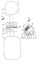
- the servomotor 1 which can correspond to the direct current motor 11 from DE-B-2 822 681 or the motor 40.2 from DE-A-3 226 435, has an actuator 2 which, for example can be the output shaft of the servomotor.
- the actuator 2 which rotates when the servomotor 1 is activated adjusts the mirror 3 in a manner which is not shown, but is known from the publications mentioned, about an axis (not shown) which, when mounted on the motor vehicle Wing mirror has essentially horizontal and transverse to the direction of travel of the vehicle.
- An actuator 2 penetrates a central axial bore of a substantially cylindrical plate 4, which contains a ball 6 pressed inwards by a spring 5 in a radial bore.
- the spring 5 is supported in a manner not shown, for example via a counter screw screwed into the bore on the plate 4.
- the ball 6 engages in a small depression on the circumference of the actuator 2 and thus couples the plate 4 to the actuator 2. Therefore, the plate 4 takes part in the rotary movements of the actuator 2.
- the plate 4 has a radial cutout 7 shown hatched in FIG. 2 in the circumferential direction, in which a nose 8 protruding radially from the actuator 2 is captured.
- the cutout 7 is sector-shaped and extends from the central bore of the plate 4 to a ring gear 9 on the periphery of the plate 4 which is transverse to the actuator 2.
- the recess 7 extends over a circumferential angle alpha, which will be discussed later.
- the actuator 2 is surrounded by a magnetic coil 20, the armature 21 of which points to the end face of the plate 4 provided with the toothing 9 and is also provided on its edge with a toothing (not shown in detail) for engaging the toothing 9.
- the solenoid 20, like the servomotor 1, is stationary relative to the mirror 3.
- the described device works as follows: By actuating a switch on the dashboard (cockpit) by the driver, the latter activates the servomotor 1, possibly via a control unit (not shown), in such a way that the mirror 3, as part of the right-hand exterior mirror when the vehicle is steered to the left, assumes the correct position for the driver, to allow him to look back in the usual way while driving.
- the rotation of the actuator 2 generated by the activation of the servomotor 1 is followed by the plate 4 without slippage due to the engagement of the spring-loaded ball 6 in the recess of the actuator 2.
- the nose 8 sits on a boundary edge 10 of the cutout 7.
- the spring 5 is dimensioned in this way that the system of the nose 8 on the boundary 10 is retained even when the actuator 2 rotates counterclockwise when viewing FIG. 2.
- a circuit for the magnetic coil 20 is first closed in the motor vehicle when reverse gear is engaged.
- the magnetic attraction then developed by the magnet coil 20 pulls the plate 4 towards itself a small distance along the actuator 2 until the toothings 22 and 9 come into engagement.
- the ball 6 leaves its stable position in the recess of the actuator 2.
- the cutout 7 has a sufficient axial depth to enable the axial movement of the plate 4 relative to the nose 8. Due to the engagement of the toothings 9 and 22, the plate 4 is fixed in place with the magnet coil 20, so that it can no longer rotate with the actuator 2.
- the servomotor 1 When the reverse gear is engaged, the servomotor 1 is also activated for a predetermined period of time in a direction of rotation, which causes the mirror 3 to tilt downward.
- the time span is sufficient to allow the nose 8 to run from the stop edge 10 of the cutout 7 to the opposite stop edge 12 of the cutout 7.
- the slip clutch usually present in the servomotor 1 makes it harmless that the servomotor 1 may run longer, depending on the function, than the movement of the nose 8 from the stop edge 10 to the stop edge 12 requires.
- the mirror 3 When the nose 8 abuts the stop edge 12, the mirror 3 is tilted in such a way that it allows the driver a view of the right rear wheel and the right rear part of his vehicle and thus enables control of whether he touches the curb or similar obstacles, for example happens when reversing his vehicle.
- the servomotor 1 is activated by the predetermined time in the opposite direction of rotation, so that the mirror returns to its starting position, in which the nose 8 returns within the cutout sector 7 to the stop edge 10.
- the ball 6 is in the region of the recess in the actuator 2, so that the ball 6 in the recess returns to the stable position under the action of the spring 5, which results in an axial displacement of the plate 4th relative to the magnet coil 20 by a distance that disengages the teeth 9 and 22.
- the mirror 3 has thus assumed its starting position. Then the circuit for the magnetic coil 20 is interrupted so that it no longer exerts a magnetic holding force on the plate 4.
- the locking device is again in the initial situation. It goes without saying that measures have been taken which block a normal positional adjustment of the mirror during its described operation as a parking aid.
- FIGS. 3 and 4 Another embodiment of the invention is shown in FIGS. 3 and 4.
- a reduction gear designated as a whole by 30, is coupled in a manner not shown to the output pinion of the servomotor, not shown.
- a first encoder wheel 32 consists of a cage with internal teeth, from the base of which a pinion 34 with external teeth and a smaller diameter projects outwards.
- a circular plate 36 is held by means of a spring ring 38 against the end wall 31 of the cage 32 facing the pinion 34 and has a central bore 37 for this purpose. The plate 36 can be pushed from the free end of the pinion 34 over the latter against the end wall 31, the pinion 34 then penetrating the bore 37, and the spring ring 38 surrounding the pinion 34 is supported on the pinion 34 in a manner not shown.
- a nose 35 protrudes axially into an arcuate slot 33, which is cut into the base of the end face 31 of the cage 32, and, as can be seen in FIG. 4, is a circular arc around the axis of the cage 32 Alpha angle extends.
- the plate 36 is provided on its periphery with a ring gear 39, in which the ring gear 41 of a stop plate 42 can engage.
- the stop plate 42 is seated at the free end of an armature 44 of a magnet coil 46 and is under the load of a spring 48 which presses the stop plate 42 with armature 44 away from the magnet coil 46 and thus the teeth 41 of the stop plate 42 normally out of engagement with the ring gear 39 the plate 36 holds.
- the pinion 34 can mesh in a manner not shown with the toothed section of a transmission element connected to the mirror, not shown, which is known, for example, from the last-mentioned German Offenlegungsschrift.
- the magnet coil 46 is held stationary relative to the mirror, that is to say, for example, is fastened to the mirror housing in the cup surrounding the servomotor.
- the mode of operation of this embodiment of the invention corresponds to that of the first embodiment. If the mirror is to serve as a parking aid, the magnetic coil 46 is activated when the reverse gear is engaged, with the result that the stop plate 42 is tightened against the plate 46 and against the action of the spring 48, so that its toothing 41 with the ring gear 39 of the plate 36 comes into engagement. Since the stop plate 42 is held non-rotatably in the magnet coil 46, the plate 36 is also prevented from further rotation by the gear 30. If the servomotor is now activated for rotation over the aforementioned predetermined period of time, there is a slip between the cage 32 with pinion 34 and the plate 36 such that the nose 35 is in the longitudinal slot 33 from its first end 50 to its other end 52 moves.
- the size of the angle alpha is evidently determined by how far the mirror has to be tilted from its initial position in order to give the driver a view of the right rear wheel or the right rear part and its surroundings.
- the driver should be free to use the parking aid by tilting the mirror by actuating or not actuating a switch provided for this purpose on the dashboard. With such an additional switch it is also achieved that the parking aid described only comes into operation when the reverse gear is actually engaged for parking the vehicle. It is also within the scope of the invention, after the reverse gear has been removed, to return the mirror tilted to the parking aid into its initial position only after a time delay of about half a minute by means of a correspondingly delayed activation of the servomotor. This time delay takes into account the fact that when parking is often switched relatively often between the first gear and reverse gear and under these operating conditions it should be prevented that the mirror returns to its starting position accordingly frequently and tips again.
Description
- Die Erfindung betrifft einen Außenspiegel für ein Kraftfahrzeug mit einem an dem Kraftfahrzeug befestigbaren Spiegelgehäuse, welches einen um wenigstens eine Achse verschwenkbaren und über ein Verbindungsglied mit einem Stellmotor gekoppelten Spiegel trägt, wobei in einen Stromversorgungskreis für den Stellmotor ein Umschalter für die Drehrichtung des Stellmotors geschaltet ist und wobei ein Steuerorgan für einen Rückwärtsgang des Kraftfahrzeuges mit dem Umschalter zu dessen Betätigung sowie mit einem voreingestellten Wegbegrenzer für die Drehbewegung des Verbindungsgliedes gekoppelt ist. Ein solcher Außenspiegel ist zum Beispiel aus dem Dokument JP-A-58-67538 oder JP-A-58-224827 schon bekannt.
- In der DE-A-2 715 575 ist ein Außenspiegel für ein Kraftfahrzeug beschrieben, in dessen Spiegelgehäuse ein Stellmotor zum Verstellen eines Rückspiegels befestigt ist. Der Stellmotor ist über ein Untersetzungsgetriebe mit dem Spiegel gekoppelt, so daß letzerer bei entsprechender Aktivierung des Stellmotors um eine Achse verdreht werden kann. Wenn der Außenspiegel an dem Kraftfahrzeug befestigt ist, erstreckt sich diese Achse im wesentlichen horizontal vom Fahrzeug weg. Der Stellmotor kann vom Fahrer durch Betätigen eines Schalters solange aktiviert werden, bis der Spiegel die für die Sitzposition des Fahrers günstigste Stellung eingenommen hat.
- Bei linksgesteuerten Fahrzeugen ist es üblich, auf der rechten Fahrzeugseite einen Außenspiegel anzubringen, der dem Fahrer beispielsweise bei Überholvorgängen das Geschehen rechts hinter seinem Fahrzeug sichtbar macht.
- Besonderes Geschick wird vom Fahrer beim Einparken in Parklücken verlangt, insbesondere wenn die Parkfläche von einem erhabenen Bordstein begrenzt ist. Bei linksgesteuerten Fahrzeugen ist das hintere untere Ende des Fahrzeugs für den Fahrer durch den rechten Außenspiegel nicht einsehbar, es sei denn, der Fahrer verstellt den rechten Außenspiegel soweit nach unten, daß ihm die fehlende Sicht ermöglicht wird.
- Eine derartige Verstellung des Außenspiegels erfordert daher eine zusätzliche Manipulation des Fahrers, die ihn vom eigentlichen Einparken ablenkt. Darüberhinaus besteht die Gefahr, daß der Fahrer bei Weiterfahrt die Rückstellung des Spiegels in die normale, die Sicht auf das Verkehrsgeschehen rechts hinter seinem Fahrzeug ermöglichende Stellung vergißt bezw. wegen der Stellung des Fahrzeugs nicht mehr einstellen kann, so daß der verstellte rechte Außenspiegel im Bedarfsfall nicht das erwartete Sichtfeld wiedergibt.
- Aus dem Dokument JP-A-58-67538 ist ein Außenspiegel für ein Kraftfahrzeug mit Rückwärtsgang bekannt, bei welchem ein Fühler zur Feststellung einer Fahrtrichtungsänderung einen Mikroprozessor beaufschlagt. Der Mikroprozessor veranlaßt bei Empfang entsprechender Signale aus dem Fühler einen Antriebsmotor für den Spiegel letzeren um einen vorbestimmten Winkel zu drehen. In dem Dokument JP-A-58-224829 ist zu dem gleichen Zweck eine elektronische Schaltung vorgesehen, welche bei Feststellung einer Rückwärtsfahrt den Spiegel durch entsprechende Beaufschlagung seines Antriebsmotors um einen vorbestimmten Winkelbetrag kippen läßt.
- Der Erfindung liegt mithin die Aufgabe zugrunde, einen Außenspiegel für ein Kraftfahrzeug mit Rückwärtsgang zu schaffen, der dem Fahrer beim Rückwärts-Einparken eine wirksame, mit wenigen Bauteilen kostengünstig zu realisierende Sichthilfe bietet, ohne die während der Fahrt erforderliche Sicht nach hinten zu erschweren.
- Dazu ist bei dem eingangs genannten Außenspiegel erfindungsgemäß vorgesehen, daß der Wegbegrenzer eine vom Steuerorgan betätigbare elektromagnetische Kupplung mit zwei Kupplungsteilen aufweist.
- In bevorzugter Ausgestaltung der Erfindung ist vorgesehen, daß eines der Kupplungsteile mit einer axialen Nase in eine Ausnehmung im anderen Kupplungsteil bei betätigter Kupplung eingreift. Das Verbindungsglied kann danach bei Aktivierung des Stellmotors nur soweit gedreht werden, als die Nase im Ausschnitt beweglich ist.
- In zweckmäßiger Weiterbildung der Erfindung sitzt auf dem Verbindungsglied ein plattenförmiges Kupplungsteil unter Federdruck, welches mit einem ringförmigen Profil, etwa einer peripheren Verzahnung, versehen ist, in welche ein mit einem Gegenprofil versehene Stopelement bei Aktivierung der Kupplung eingreift.
- Das Verbindungsglied kann die Abtriebswelle des Stellmotors oder alternativ ein Ritzel eines Untersetzungsgetriebes sein, welches zwischen Stellmotor und Spiegel vorgesehen ist.
- Gemäß einer weiteren bevorzugten Ausführungsform der Erfindung weist ein elektronischer Wegbegrenzer einen voreingestellten Zähler auf, der ausgehend von einer Nullage die vom Gleichstrom-Stellmotor am Kommutator erzeugten Impulse bis zu einem voreingestellten Höchstzählstand zählt. Ist der Höchstzählstand erreicht, gibt der Zähler ein die weitere Stromversorgung des Stellmotors unterbrechendes Signal ab. Diese Ausführungsform der Erfindung enthält nur wenige preisgünstige elektroniche Bauteile und zeichnet sich durch hohe Betriebssicherheit und Verschleißfestigkeit aus. Der Höchstzählstand kann werksseitig eingestellt und danach bemessen werden, daß das Verbindungsglied eine zum erforderlichen Abkippen des Spiegels erforderliche Drehbewegung ausführen kann.
- Die Erfindung wird nachstehend anhand der beigefügten Schemazeichnung im einzelnen erläutert. Es zeigen:
- Fig. 1:
- eine schematische Darstellung zur Erläuterung der Funktionsweise einer ersten Ausführungsform eines Spiegelantriebs für einen Außenspiegel;
- Fig. 2:
- eine schematische Stirnansicht der Vorrichtung nach Fig. 1;
- Fig. 3:
- eine schematische Darstellung der Funktionsweise einer anderen Ausführungsform des Spiegelantriebs nach Fig. 1; und
- Fig. 4:
- eine schematische Darstellung einer stirnseitigen Ansicht der Vorrichtung aus Fig. 3.
- Die Erfindung eignet sich zum Einbau in einen Kraftfahrzeug-Außenspiegel, wie er in der DE-B-2 822 681 oder in der DE-A-3 226 435 beschrieben ist. Durch Vergleich des Inhalts der beiden Schriften ergibt sich, daß es für die Erfindung nicht darauf ankommt, ob wie bei der DE-B-2 822 681 der Spiegel relativ zum Spiegelgehäuse unbeweglich in diesem gehalten ist und die aus Spiegel und Gehäuse bestehende Baugruppe relativ zu einem am Kraftfahrzeug befestigbaren Spiegelfuß durch den Stellmotor elektrisch vom Inneren des Fahrzeuges aus verstellt werden kann, oder ob gemäß DE-A-3 226 435 der Spiegel innerhalb des mit dem Spiegelfuß fest (jedoch ggf. nach vorne und hinten klappbar) verbundenen Spiegelgehäußes durch den Stellmotor relativ zum Spiegelgehäuse verstellt werden kann. Entscheidend ist eine vom Stellmotor erzeugte Relativbewegung des Spiegels zu demjenigen Bauteil des Außenspiegels, auf welchem der Stellmotor fest befestigt ist.
- In der schematischen Darstellung der Erfindung nach Fig. 1 besitzt der Stellmotor 1, der dem Gleichstrommotor 11 aus der DE-B-2 822 681 oder dem Motor 40.2 aus der DE-A-3 226 435 entsprechen kann, ein Stellorgan 2, welches beispielsweise die Abtriebswelle des Stellmotors sein kann. Das bei aktiviertem Stellmotor 1 drehende Stellorgan 2 verstellt den Spiegel 3 in nicht dargestellter, jedoch aus den genannten Druckschriften bekannter Weise um eine nicht dargestellte Achse, die bei an das Kraftfahrzeug angebautem Außenspiegel im wesentlichen horizontal und quer zur Fahrtrichtung des Fahrzeugs weist.
- Ein Stellorgan 2 durchdringt eine mittige Axialbohrung einer im wesentlichen zylindrischen Platte 4, welche in einer Radialbohrung eine von einer Feder 5 nach innen gedrückte Kugel 6 enthält. Die Feder 5 stützt sich in nicht dargestellter Weise beispielsweise über eine in die Bohrung eingeschraubte Gegenschraube an der Platte 4 ab. Die Kugel 6 greift bei der in Fig. 2 dargestellten Ausgangsstellung in eine kleine Einsenkung am Umfang des Stellorgans 2 ein und koppelt somit die Platte 4 mit dem Stellorgan 2. Daher nimmt die Platte 4 an den Drehbewegungen des Stellorgans 2 teil.
- Die Platte 4 besitzt einen in Fig. 2 schraffiert dargestellten radialen Ausschnitt 7 in Umfangsrichtung, in welchem eine aus dem Stellorgan 2 radial vorstehende Nase 8 eingefangen ist. Der Ausschnitt 7 ist sektorförmig und erstreckt sich von der zentralen Bohrung der Platte 4, bis zu einem Zahnkranz 9 an der zum Stellorgan 2 querliegenden Peripherie der Platte 4.
- Die Ausnehmung 7 erstreckt sich über einen Umfangswinkel Alpha, auf den noch eingegangen wird.
- Das Stellorgan 2 ist von einer Magnetspule 20 umgeben, deren Anker 21 auf die mit der Verzahnung 9 versehene Stirnfläche der Platte 4 zuweist und an seinem Rand ebenfalls mit einer nicht im einzelnen dargestellten Verzahnung zum Eingriff in die Verzahnung 9 versehen ist. Die Magnetspule 20 ist ebenso wie der Stellmotor 1 relativ zum Spiegel 3 ortsfest.
- Die beschriebene Vorrichtung arbeitet wie folgt:
Durch Betätigung etwa eines Schalters am Amaturenbrett (Cockpit) durch den Fahrer aktiviert dieser den Stellmotor 1 gegebenenfalls über eine nicht dargestellte Steuereinheit in der Weise, daß der Spiegel 3 als Bestandteil des bei links gelenktem Kraftfahrzeug rechten Außenspiegels die für den Fahrer richtige Stellung einnimmt, um ihm den Blick nach hinten während der Fahrt in üblicher Weise zu ermöglichen. Der durch die Aktivierung des Stellmotors 1 erzeugten Drehung des Stellorgans 2 folgt die Platte 4 schlupflos vermöge des Eingriffs der federbelasteten Kugel 6 in die Vertiefung des Stellorgans 2. Dabei sitzt die Nase 8 an einer Begrenzungskante 10 des Ausschnitts 7. Die Feder 5 ist so bemessen, daß die Anlage der Nase 8 an der Begrenzung 10 auch dann erhalten bleibt, wenn sich das Stellorgan 2 bei Betrachtung der Fig. 2 im Gegensinn des Uhrzeigers dreht. - Wenn der Fahrer den Spiegel 3 als Einparkhilfe verwenden möchte, wird im Kraftfahrzeug bei Einlegen des Rückwärtsgangs zunächst ein Stromkreis für die Magnetspule 20 geschlossen. Die daraufhin von der Magnetspule 20 entwickelte magnetische Anziehung zieht die Platte 4 um ein geringes Stück axial längs des Stellorgans 2 auf sich zu, bis die Verzahnungen 22 und 9 in Eingriff kommen. Dabei verläßt die Kugel 6 ihre stabile Lage in der Ausnehmung des Stellorgans 2. Es versteht sich, daß dazu der Ausschnitt 7 eine hinreichende axiale Tiefe besitzt, um die axiale Bewegung der Platte 4 relativ zur Nase 8 zu ermöglichen. Durch den Eingriff der Verzahnungen 9 und 22 ist die Platte 4 mit der Magnetspule 20 ortsfest gelegt, so daß diese nicht mehr mit dem Stellorgan 2 mitdrehen kann. Mit dem Einlegen des Rückwärtsgangs ist auch der Stellmotor 1 um eine vorgegebene Zeitspanne zu einer Drehrichtung aktiviert, die das Abwärtskippen des Spiegels 3 zur Folge hat. Die Zeitspanne reicht aus, die Nase 8 von der Anschlagkante 10 des Ausschnitts 7 bis gegen die gegenüberliegende Anschlagkante 12 des Ausschnitts 7 anlaufen zu lassen. Die im Stellmotor 1 üblicherweise vorhandene Rutschkupplung macht es unschädlich, daß der Stellmotor 1 gegebenenfalls funktionsbedingt länger läuft als die Bewegung der Nase 8 von der Anschlagkante 10 zur Anschlagkante 12 erfordert. Wenn die Nase 8 an der Anschlagkante 12 anliegt, ist der Spiegel 3 so gekippt, daß er dem Fahrer einen Blick auf das rechte Hinterrad und den rechten hinteren Teil seines Fahrzeugs erlaubt und somit die Kontrolle ermöglicht, ob er beispielweise den Bordstein oder dergleichen Hindernisse berührungslos beim Rückwärtssetzen seines Fahrzeugs passiert.
- Wird der Rückwärtsgang herausgenommen, wird der Stellmotor 1 um die vorgegebene Zeitspanne in umgekehrter Drehrichtung aktiviert, so daß der Spiegel wieder in seine Ausgangslage zurückkehrt, bei der die Nase 8 innerhalb des Ausschnittssektors 7 zur Anschlagkante 10 zurückkehrt. Bei dieser Lage der Platte 4 relativ zum Stellorgan 2 befindet sich die Kugel 6 im Bereich der Ausnehmung im Stellorgan 2, so daß die Kugel 6 in der Ausnehmung in die stabile Lage unter der Wirkung der Feder 5 zurückkehrt, was eine axiale Verschiebung der Platte 4 relativ zur Magnetspule 20 um eine Strecke zur Folge hat, die die Verzahnungen 9 und 22 außer Eingriff bringt. Der Spiegel 3 hat damit seine Ausgangslage eingenommen. Sodann wird der Stromkreis für die magnetische Spule 20 unterbrochen, so daß sie keine magnetische Haltekraft auf die Platte 4 mehr ausübt. Die Arretiervorrichtung befindet sich wieder in der Ausgangssituation. Es versteht sich, daß Maßnahmen getroffen sind, die eine übliche Positionsverstellung des Spiegels während seines beschriebenen Betriebs als Einparkhilfe sperren.
- Eine andere Ausführungsform der Erfindung zeigen die Figuren 3 und 4. Ein im Ganzen mit 30 bezeichnetes Untersetzungsgetriebe ist in nicht dargestellter Weise mit dem Abtriebsritzel des nicht dargestellten Stellmotors gekoppelt. Ein erstes Gebtrieberad 32 besteht aus einem Käfig mit Innenverzahnung, aus dessen Basis mittig ein Ritzel 34 mit Außenverzahnung und kleinerem Durchmesser nach außen vorsteht. Eine kreisrunde Platte 36 ist mittels eines Federrings 38 gegen die auf das Ritzel 34 zuweisende Stirnwand 31 des Käfigs 32 in axialer Ausrichtung gehalten und weist dazu eine zentrale Bohrung 37 auf. Die Platte 36 kann vom freien Ende des Ritzels 34 her über letzteres gegen die Stirnwand 31 aufgeschoben werden, wobei das Ritzel 34 dann die Bohrung 37 durchdringt, und der das Ritzel 34 umgebende Federring 38 stützt sich in nicht dargestellter Weise auf dem Ritzel 34 ab. Aus der Platte 36 steht eine Nase 35 axial in einen kreisbogenförmigen Schlitz 33 vor, welcher von der Stirnseite 31 des Käfigs 32 her in dessen Basis eingeschnitten ist, und, wie Fig. 4 erkennen läßt, sich kreisbogenförmig um die Achse des Käfigs 32 um den Winkel Alpha erstreckt. Die Platte 36 ist an ihrer Peripherie mit einem Zahnkranz 39 versehen, in welchen der Zahnkranz 41 eines Stoppbleches 42 eingreifen kann. Das Stoppblech 42 sitzt am freien Ende eines Ankers 44 einer Magnetspule 46 und steht unter der Belastung einer Feder 48, welche das Stoppblech 42 mit Anker 44 von der Magnetspule 46 weg drückt und damit die Verzahnung 41 des Stoppbleches 42 normalerweise außer Eingriff mit dem Zahnkranz 39 der Platte 36 hält.
- Das Ritzel 34 kann in nicht dargestellter Weise mit dem gezahnten Abschnitt eines mit dem nicht dargestellten Spiegel verbundenen Übertragungsgliedes kämmen, welches beispielsweise aus der letzterwähnten Deutschen Offenlegungsschrift bekannt ist. Die Magnetspule 46 ist relativ zum Spiegel ortsfest gehalten, also beispielsweise an dem Spiegelgehäuse in dem den Stellmotor umgebenden Becher befestigt.
- Die Wirkungsweise dieser Ausführungsform der Erfindung entspricht derjenigen des ersten Ausführungsbeispiels. Soll der Spiegel als Parkhilfe dienen, wird bei Einlegen des Rückwärtsgangs die Magnetspule 46 aktiviert mit der Folge, daß das Stoppblech 42 gegen die Platte 46 und gegen die Wirkung der Feder 48 angezogen wird, so daß dessen Verzahnung 41 mit dem Zahnkranz 39 der Platte 36 in Eingriff kommt. Da das Stoppblech 42 unverdrehbar in der Magnetspule 46 gehalten ist, wird auch die Platte 36 an weiterer Drehung mit dem Getriebe 30 gehindert. Wenn der Stellmotor jetzt über die erwähnte vorgegebene Zeitspanne zur Drehung aktiviert wird, ergibt sich ein Schlupf zwischen dem Käfig 32 mit Ritzel 34 und der Platte 36 dergestalt, daß die Nase 35 sich in dem Längschlitz 33 von dessen erstem Ende 50 bis zu dessen anderen Ende 52 bewegt. Eine weitere Drehung des mit dem Käfig 32 einteiligen Ritzels 34 ist wegen der Arretierung der Platte 36 durch das Stoppblech 42 nicht mehr möglich. Beim Herausnehmen des Rückwärtsganges wird wie erwähnt der Stellmotor über die vorgegebene Zeitspanne zur Drehung in umgekehrtem Sinne aktiviert mit der Folge, daß der Käfig 32 mit Ritzel 34 eine Drehung relativ zur festgehaltenen Platte 36 derart ausführen, daß die Nase 35 vom Ende 52 zum Ende 50 des Schlitzes 33 gelangt. Der Spiegel hat jetzt wieder seine Ausgangslage eingenommen. Sodann kann der Stromversorgungskreis für die Magnetspule 46 unterbrochen werden, so daß die Platte 36 aus ihrer Arretierung gelöst wird und mit dem Untersetzungsgetriebe 30 ungehindert mitdrehen kann. Dabei ist die Federkraft des Federrings 38 so gemessen, daß die Platte 36 jeder Drehung des Getriebes 30 folgt, ohne daß die Nase 35 ihre Lage am Ende 50 des Schlitzes 33 verändert.
- Die Größe des Winkels Alpha bestimmt sich ersichtlich danach, wieweit der Spiegel aus seiner Ausgangslage abgekippt werden muß, um dem Fahrer die Sicht auf das rechte Hinterrad bzw. den rechten hinteren Teil und dessen Umgebung zu gewähren.
- Es versteht sich ferner, daß dem Fahrer die Inanspruchnahme der Einparkhilfe durch Abkippen des Spiegels durch entsprechende Betätigung oder Nichtbetätigung eines dafür am Armaturbrett vorgesehenen Schalters freigestellt sein sollte. Mit einem derartigen Zusatzschalter wird auch erreicht, daß die beschriebene Parkhilfe nur dann in Funktion tritt, wenn das Einlegen des Rückwärtsganges tatsächlich zum Einparken des Fahrzeugs geschieht. Es liegt weiterhin im Rahmen der Erfindung, nach Herausnahme des Rückwärtsganges den zur Parkhilfe abgekippten Spiegel erst nach einer Zeitverzögerung von etwa einer halben Minute durch entsprechend verzögerte Aktivierung des Stellmotors wieder in seine Ausgangslage zurückzuführen. Diese Zeitverzögerung trägt dem Umstand Rechnung, daß beim Einparken oft relativ häufig zwischen erstem Gang und Rückwärtsgang gewechselt und unter diesen Betriebsbedingungen verhindert werden soll, daß der Spiegel entsprechend häufig wieder in seiner Ausgangslage zurückkehrt und wieder abkippt.
Claims (7)
- Außenspiegel für ein Kraftfahrzeug mit einem an dem Kraftfahrzeug befestigbaren Spiegelgehäuse, welches einen um wenigstens eine, Achse verschwenkbaren und über ein Verbindungsglied mit einem Stellmotor (1; 80) gekoppelten Spiegel (3) trägt, wobei in einen Stromversorgungskreis für den Stellmotor ein Umschalter (60) für die Drehrichtung des Stellmotors geschaltet ist, und wobei ein Steuerorgan (70) für einen Rückwärtsgang des Kraftfahrzeuges mit dem Umschalter (60) zu dessen Betätigung sowie mit einem voreingestellten Wegbegrenzer (4; 36; 98) für die Drehbewegung des Verbindungsgliedes (2, 30) gekoppelt ist, dadurch gekennzeichnet, daß der Wegbegrenzer eine vom Steuerorgan (70) betätigbare elektromagnetische Kupplung (20, 4; 46, 36) mit zwei Kupplungsteilen (4, 20; 36, 32) aufweist.
- Außenspiegel nach Anspruch 1, dadurch gekennzeichnet, daß eines der Kupplungsteile mit einer axialen Nase (8; 35) in eine Ausnehmung (12; 33) des anderen Kupplungsteiles bei betätigter Kupplung eingreift.
- Außenspiegel nach Anspruch 2, dadurch gekennzeichnet, daß die Ausnehmung (35) bogenförmig gestaltet ist.
- Außenspiegel nach einem der Ansprüche 1 bis 3, dadurch gekennzeichnet, daß eine Magnetspule (20, 46) vorgesehen ist, deren Anker (22, 42) bei Aktivierung ein vom Verbindungsglied normalerweise mitgenommenes Kupplungsteil (4, 36) festlegt.
- Außenspiegel nach einem der Ansprüche 1 bis 4, dadurch gekennzeichnet, daß auf dem Verbindungsglied (2, 30) ein plattenförmiges erstes Kupplungsteil (4, 36) unter Federdruck (5, 38), welches mit einem ringförmigen Profil, etwa peripheren Verzahnung (9, 39), vorgesehen ist, in welche ein mit einem Gegenprofil (22, 41) versehenes Stoppelement (22, 42) bei Aktivierung der Kupplung eingreift.
- Außenspiegel nach einem der vorstehenden Ansprüche, dadurch gekennzeichnet, daß das Verbindungsglied die Abtriebswelle (2) des Stellmotors (1) ist.
- Außenspiegel nach einem der Ansprüche 1 bis 6, dadurch gekennzeichnet, daß das Verbindungsglied ein Ritzel (32) eines Untersetzungsgetriebes (30) ist, welches zwischen Stellmotor (1) und Spiegel (3) vorgesehen ist.
Priority Applications (1)
| Application Number | Priority Date | Filing Date | Title |
|---|---|---|---|
| AT89110195T ATE100030T1 (de) | 1988-06-09 | 1989-06-06 | Aussenspiegel fuer ein kraftfahrzeug mit rueckwaertsgang. |
Applications Claiming Priority (4)
| Application Number | Priority Date | Filing Date | Title |
|---|---|---|---|
| DE19883819597 DE3819597C2 (de) | 1988-06-09 | 1988-06-09 | Bei Einlegen des Rückwärtsganges schwenkbarer Außenspiegel |
| DE3819597 | 1988-06-09 | ||
| DE3901442 | 1989-01-19 | ||
| DE19893901442 DE3901442C1 (de) | 1989-01-19 | 1989-01-19 |
Publications (2)
| Publication Number | Publication Date |
|---|---|
| EP0348700A1 EP0348700A1 (de) | 1990-01-03 |
| EP0348700B1 true EP0348700B1 (de) | 1994-01-12 |
Family
ID=25868955
Family Applications (1)
| Application Number | Title | Priority Date | Filing Date |
|---|---|---|---|
| EP89110195A Expired - Lifetime EP0348700B1 (de) | 1988-06-09 | 1989-06-06 | Aussenspiegel für ein Kraftfahrzeug mit Rückwärtsgang |
Country Status (6)
| Country | Link |
|---|---|
| US (1) | US4936671A (de) |
| EP (1) | EP0348700B1 (de) |
| CA (1) | CA1323233C (de) |
| DE (1) | DE58906671D1 (de) |
| ES (1) | ES2048786T3 (de) |
| MX (1) | MX172837B (de) |
Families Citing this family (21)
| Publication number | Priority date | Publication date | Assignee | Title |
|---|---|---|---|---|
| JPH0756099A (ja) * | 1993-06-07 | 1995-03-03 | Minolta Co Ltd | 回転偏向器及び光ビーム走査光学装置 |
| US5719713A (en) * | 1994-02-28 | 1998-02-17 | Ultra-View Technology, Inc. | Automatic side view mirror tracking system |
| US5624176A (en) * | 1995-10-25 | 1997-04-29 | Donnelly Corporation | Illuminated power tilt exterior mirror for vehicle |
| US5798575A (en) | 1996-07-11 | 1998-08-25 | Donnelly Corporation | Vehicle mirror digital network and dynamically interactive mirror system |
| US5796176A (en) | 1996-07-11 | 1998-08-18 | Donnelly Corporation | Memory mirror system for vehicles |
| JP3508909B2 (ja) * | 1997-07-01 | 2004-03-22 | 株式会社村上開明堂 | バックミラーの急速変角制御装置 |
| FR2795031B1 (fr) * | 1999-06-18 | 2001-07-13 | Renault | Retroviseur pour vehicule automobile |
| DE19928384A1 (de) | 1999-06-21 | 2001-01-11 | Hohe Gmbh & Co Kg | Außenrückspiegel mit Trockenkammer |
| US6698905B1 (en) * | 2000-05-16 | 2004-03-02 | Donnelly Corporation | Memory mirror system for vehicle |
| US7360908B1 (en) * | 2000-06-23 | 2008-04-22 | Visiocorp Patents S.A.R.L. | Exterior mirror for motor vehicle |
| US6580992B2 (en) | 2000-10-31 | 2003-06-17 | Honda Giken Kogyo Kabushiki Kaisha | Rear view mirror tilt control |
| JP3754889B2 (ja) * | 2000-11-20 | 2006-03-15 | キヤノン株式会社 | ズームレンズ |
| JP4615766B2 (ja) * | 2000-12-15 | 2011-01-19 | 本田技研工業株式会社 | 駐車支援装置 |
| DE10148611B4 (de) | 2001-10-02 | 2005-01-27 | Mekra Lang Gmbh & Co. Kg | Vorrichtung zum schwenkbeweglichen Lagern eines Tragarms für einen Aussenspiegel |
| JP4303593B2 (ja) * | 2001-10-30 | 2009-07-29 | シェフェネイカー・ヴィジョン・システムズ・オーストラリア・プロプライアタリー・リミテッド | 乗物用動力支援式伸縮ミラー組立体 |
| JP2003312364A (ja) * | 2002-04-19 | 2003-11-06 | Murakami Corp | 車両用ミラーの角度制御装置 |
| US7217191B2 (en) * | 2003-01-16 | 2007-05-15 | Mark Allen Justin Cordell | Gaming device with retractable remote controller |
| US7025467B2 (en) * | 2003-06-23 | 2006-04-11 | Meyer Lee G | Outside, vehicle rearview mirror system for backing |
| US6965821B1 (en) | 2004-07-07 | 2005-11-15 | Daimlerchrysler Corporation | Tilt in reverse mirror |
| JP5038606B2 (ja) * | 2005-08-01 | 2012-10-03 | 株式会社村上開明堂 | 電動ミラー制御装置 |
| KR100778560B1 (ko) | 2006-10-16 | 2007-11-22 | 현대자동차주식회사 | 차량 사이드 미러의 구동 시스템 및 구동 방법 |
Citations (2)
| Publication number | Priority date | Publication date | Assignee | Title |
|---|---|---|---|---|
| JPS5867538A (ja) * | 1981-10-15 | 1983-04-22 | Toyota Motor Corp | 車両用バツクミラ−の角度制御装置 |
| FR2585200A1 (fr) * | 1985-07-18 | 1987-01-23 | Jaeger | Procede et dispositif de commande de moteur a courant continu |
Family Cites Families (6)
| Publication number | Priority date | Publication date | Assignee | Title |
|---|---|---|---|---|
| US2871761A (en) * | 1957-01-02 | 1959-02-03 | Frank T Suyder | Automobile safety mirror |
| JPS57144145A (en) * | 1981-02-27 | 1982-09-06 | Ichikoh Ind Ltd | Angle change control device of electric remote control mirror |
| JPS58224826A (ja) * | 1982-06-25 | 1983-12-27 | Ichikoh Ind Ltd | 電動式リモ−トコントロ−ルミラ−の自動変角制御装置 |
| GB2148814B (en) * | 1983-10-26 | 1987-03-18 | Datom Limited | Vehicle rear view mirrors |
| DE3427988A1 (de) * | 1984-07-28 | 1986-02-06 | Adam Opel AG, 6090 Rüsselsheim | Aussenrueckspiegel auf der fahrerseite eines kraftfahrzeuges |
| DE3727288C2 (de) * | 1987-02-20 | 1994-10-20 | Miroslaw Janowicz | Verstellvorrichtung für eine Spiegelscheibe eines Kraftfahrzeugaußenrückblickspiegels |
-
1989
- 1989-06-06 ES ES89110195T patent/ES2048786T3/es not_active Expired - Lifetime
- 1989-06-06 DE DE89110195T patent/DE58906671D1/de not_active Expired - Fee Related
- 1989-06-06 EP EP89110195A patent/EP0348700B1/de not_active Expired - Lifetime
- 1989-06-09 US US07/363,781 patent/US4936671A/en not_active Expired - Fee Related
- 1989-06-09 MX MX016387A patent/MX172837B/es unknown
- 1989-06-09 CA CA000602369A patent/CA1323233C/en not_active Expired - Fee Related
Patent Citations (2)
| Publication number | Priority date | Publication date | Assignee | Title |
|---|---|---|---|---|
| JPS5867538A (ja) * | 1981-10-15 | 1983-04-22 | Toyota Motor Corp | 車両用バツクミラ−の角度制御装置 |
| FR2585200A1 (fr) * | 1985-07-18 | 1987-01-23 | Jaeger | Procede et dispositif de commande de moteur a courant continu |
Also Published As
| Publication number | Publication date |
|---|---|
| CA1323233C (en) | 1993-10-19 |
| ES2048786T3 (es) | 1994-04-01 |
| EP0348700A1 (de) | 1990-01-03 |
| DE58906671D1 (de) | 1994-02-24 |
| MX172837B (es) | 1994-01-17 |
| US4936671A (en) | 1990-06-26 |
Similar Documents
| Publication | Publication Date | Title |
|---|---|---|
| EP0348700B1 (de) | Aussenspiegel für ein Kraftfahrzeug mit Rückwärtsgang | |
| EP1002672B1 (de) | Anhängekupplung | |
| DE19645404B4 (de) | Automatisches Lenksystem | |
| DE10009670A1 (de) | Außenrückblickspiegel für ein Kraftfahrzeug | |
| DE3923174C2 (de) | Elektrische Rückspiegelvorrichtung für ein Kraftfahrzeug | |
| DE102006048947A1 (de) | Steuereinheit und Verfahren zum Verstellen eines an ein Fahrzeug angekuppelten Anhängers | |
| DE102005050222B4 (de) | Gelenkbeschlag für ein Rückenlehnengelenk eines Kraftfahrzeugsitzes | |
| EP0850147A1 (de) | Anhängerkupplung für kraftfahrzeuge | |
| DE19612961A1 (de) | Anhängekupplung | |
| DE3211794C2 (de) | ||
| DE69907723T2 (de) | Anordnung für eine lenkung | |
| EP0580034B1 (de) | Bedienungsbaueinheit | |
| DE3819597C2 (de) | Bei Einlegen des Rückwärtsganges schwenkbarer Außenspiegel | |
| DE4041676A1 (de) | Einstellbarer fahrzeugscheinwerfer | |
| DE4122629A1 (de) | Verstellbares pedalwerk fuer kraftfahrzeuge | |
| DE4030010A1 (de) | Aussenrueckspiegel fuer fahrzeuge | |
| DE10009579A1 (de) | Außenrückblickspiegel für ein Kraftfahrzeug | |
| EP0631546B1 (de) | Scheibenwischeranlage | |
| DE4023375C2 (de) | ||
| DE3437775C2 (de) | ||
| EP2718739B1 (de) | Sensorhalterung für einen sensor zur objektdetektion | |
| EP0873254B1 (de) | Überschaltsicherung für lenkstockschalter mit automatischer rückstellung | |
| EP1512576B1 (de) | Längseinsteller für einen Fahrzeugsitz | |
| EP0838371B1 (de) | Aussenspiegel für ein Fahrzeug | |
| DE3426519A1 (de) | Drehrichtungs-nachweismessfuehler |
Legal Events
| Date | Code | Title | Description |
|---|---|---|---|
| PUAI | Public reference made under article 153(3) epc to a published international application that has entered the european phase |
Free format text: ORIGINAL CODE: 0009012 |
|
| AK | Designated contracting states |
Kind code of ref document: A1 Designated state(s): AT BE CH DE ES FR GB IT LI LU NL SE |
|
| 16A | New documents despatched to applicant after publication of the search report | ||
| 17P | Request for examination filed |
Effective date: 19900629 |
|
| 17Q | First examination report despatched |
Effective date: 19920703 |
|
| GRAA | (expected) grant |
Free format text: ORIGINAL CODE: 0009210 |
|
| AK | Designated contracting states |
Kind code of ref document: B1 Designated state(s): AT BE CH DE ES FR GB IT LI LU NL SE |
|
| REF | Corresponds to: |
Ref document number: 100030 Country of ref document: AT Date of ref document: 19940115 Kind code of ref document: T |
|
| GBT | Gb: translation of ep patent filed (gb section 77(6)(a)/1977) |
Effective date: 19940121 |
|
| REF | Corresponds to: |
Ref document number: 58906671 Country of ref document: DE Date of ref document: 19940224 |
|
| REG | Reference to a national code |
Ref country code: ES Ref legal event code: FG2A Ref document number: 2048786 Country of ref document: ES Kind code of ref document: T3 |
|
| ITF | It: translation for a ep patent filed |
Owner name: UFFICIO TECNICO ING. A. MANNUCCI |
|
| ET | Fr: translation filed | ||
| PGFP | Annual fee paid to national office [announced via postgrant information from national office to epo] |
Ref country code: CH Payment date: 19940721 Year of fee payment: 6 |
|
| PGFP | Annual fee paid to national office [announced via postgrant information from national office to epo] |
Ref country code: LU Payment date: 19940731 Year of fee payment: 6 |
|
| EPTA | Lu: last paid annual fee | ||
| PLBE | No opposition filed within time limit |
Free format text: ORIGINAL CODE: 0009261 |
|
| STAA | Information on the status of an ep patent application or granted ep patent |
Free format text: STATUS: NO OPPOSITION FILED WITHIN TIME LIMIT |
|
| 26N | No opposition filed | ||
| EAL | Se: european patent in force in sweden |
Ref document number: 89110195.8 |
|
| PG25 | Lapsed in a contracting state [announced via postgrant information from national office to epo] |
Ref country code: LU Free format text: LAPSE BECAUSE OF NON-PAYMENT OF DUE FEES Effective date: 19950606 |
|
| PG25 | Lapsed in a contracting state [announced via postgrant information from national office to epo] |
Ref country code: LI Effective date: 19950630 Ref country code: CH Effective date: 19950630 |
|
| REG | Reference to a national code |
Ref country code: CH Ref legal event code: PL |
|
| PGFP | Annual fee paid to national office [announced via postgrant information from national office to epo] |
Ref country code: GB Payment date: 19970522 Year of fee payment: 9 |
|
| PGFP | Annual fee paid to national office [announced via postgrant information from national office to epo] |
Ref country code: DE Payment date: 19970528 Year of fee payment: 9 |
|
| PGFP | Annual fee paid to national office [announced via postgrant information from national office to epo] |
Ref country code: FR Payment date: 19970616 Year of fee payment: 9 |
|
| PGFP | Annual fee paid to national office [announced via postgrant information from national office to epo] |
Ref country code: SE Payment date: 19970619 Year of fee payment: 9 Ref country code: BE Payment date: 19970619 Year of fee payment: 9 Ref country code: AT Payment date: 19970619 Year of fee payment: 9 |
|
| PGFP | Annual fee paid to national office [announced via postgrant information from national office to epo] |
Ref country code: NL Payment date: 19970630 Year of fee payment: 9 Ref country code: ES Payment date: 19970630 Year of fee payment: 9 |
|
| PG25 | Lapsed in a contracting state [announced via postgrant information from national office to epo] |
Ref country code: GB Free format text: LAPSE BECAUSE OF NON-PAYMENT OF DUE FEES Effective date: 19980606 Ref country code: AT Free format text: LAPSE BECAUSE OF NON-PAYMENT OF DUE FEES Effective date: 19980606 |
|
| PG25 | Lapsed in a contracting state [announced via postgrant information from national office to epo] |
Ref country code: SE Free format text: LAPSE BECAUSE OF NON-PAYMENT OF DUE FEES Effective date: 19980607 |
|
| PG25 | Lapsed in a contracting state [announced via postgrant information from national office to epo] |
Ref country code: ES Free format text: LAPSE BECAUSE OF NON-PAYMENT OF DUE FEES Effective date: 19980608 |
|
| PG25 | Lapsed in a contracting state [announced via postgrant information from national office to epo] |
Ref country code: BE Free format text: LAPSE BECAUSE OF NON-PAYMENT OF DUE FEES Effective date: 19980630 |
|
| BERE | Be: lapsed |
Owner name: HOHE K.G. Effective date: 19980630 |
|
| PG25 | Lapsed in a contracting state [announced via postgrant information from national office to epo] |
Ref country code: NL Free format text: LAPSE BECAUSE OF NON-PAYMENT OF DUE FEES Effective date: 19990101 |
|
| GBPC | Gb: european patent ceased through non-payment of renewal fee |
Effective date: 19980606 |
|
| PG25 | Lapsed in a contracting state [announced via postgrant information from national office to epo] |
Ref country code: FR Free format text: LAPSE BECAUSE OF NON-PAYMENT OF DUE FEES Effective date: 19990226 |
|
| EUG | Se: european patent has lapsed |
Ref document number: 89110195.8 |
|
| NLV4 | Nl: lapsed or anulled due to non-payment of the annual fee |
Effective date: 19990101 |
|
| PG25 | Lapsed in a contracting state [announced via postgrant information from national office to epo] |
Ref country code: DE Free format text: LAPSE BECAUSE OF NON-PAYMENT OF DUE FEES Effective date: 19990401 |
|
| REG | Reference to a national code |
Ref country code: FR Ref legal event code: ST |
|
| REG | Reference to a national code |
Ref country code: ES Ref legal event code: FD2A Effective date: 20010503 |
|
| PG25 | Lapsed in a contracting state [announced via postgrant information from national office to epo] |
Ref country code: IT Free format text: LAPSE BECAUSE OF NON-PAYMENT OF DUE FEES;WARNING: LAPSES OF ITALIAN PATENTS WITH EFFECTIVE DATE BEFORE 2007 MAY HAVE OCCURRED AT ANY TIME BEFORE 2007. THE CORRECT EFFECTIVE DATE MAY BE DIFFERENT FROM THE ONE RECORDED. Effective date: 20050606 |