EP0348774A2 - System consisting of at least two remotely controlled entertainment electronic devices - Google Patents
System consisting of at least two remotely controlled entertainment electronic devices Download PDFInfo
- Publication number
- EP0348774A2 EP0348774A2 EP89111064A EP89111064A EP0348774A2 EP 0348774 A2 EP0348774 A2 EP 0348774A2 EP 89111064 A EP89111064 A EP 89111064A EP 89111064 A EP89111064 A EP 89111064A EP 0348774 A2 EP0348774 A2 EP 0348774A2
- Authority
- EP
- European Patent Office
- Prior art keywords
- remote control
- memory
- additional
- transmitter
- command code
- Prior art date
- Legal status (The legal status is an assumption and is not a legal conclusion. Google has not performed a legal analysis and makes no representation as to the accuracy of the status listed.)
- Withdrawn
Links
Images


Classifications
-
- G—PHYSICS
- G11—INFORMATION STORAGE
- G11B—INFORMATION STORAGE BASED ON RELATIVE MOVEMENT BETWEEN RECORD CARRIER AND TRANSDUCER
- G11B31/00—Arrangements for the associated working of recording or reproducing apparatus with related apparatus
- G11B31/006—Arrangements for the associated working of recording or reproducing apparatus with related apparatus with video camera or receiver
-
- G—PHYSICS
- G11—INFORMATION STORAGE
- G11B—INFORMATION STORAGE BASED ON RELATIVE MOVEMENT BETWEEN RECORD CARRIER AND TRANSDUCER
- G11B15/00—Driving, starting or stopping record carriers of filamentary or web form; Driving both such record carriers and heads; Guiding such record carriers or containers therefor; Control thereof; Control of operating function
- G11B15/02—Control of operating function, e.g. switching from recording to reproducing
- G11B15/023—Control of operating function, e.g. switching from recording to reproducing remotely controlled
-
- H—ELECTRICITY
- H04—ELECTRIC COMMUNICATION TECHNIQUE
- H04B—TRANSMISSION
- H04B1/00—Details of transmission systems, not covered by a single one of groups H04B3/00 - H04B13/00; Details of transmission systems not characterised by the medium used for transmission
- H04B1/06—Receivers
- H04B1/16—Circuits
- H04B1/20—Circuits for coupling gramophone pick-up, recorder output, or microphone to receiver
- H04B1/205—Circuits for coupling gramophone pick-up, recorder output, or microphone to receiver with control bus for exchanging commands between units
Definitions
- the invention relates to a device system according to the preamble of claim 1.
- the invention is therefore based on the object of creating a possibility with which at least two electrical devices of entertainment electronics of different remote control transmission systems which are combined in a device system and can be remote-controlled next to one another can nevertheless be operated side by side with a single remote control transmitter.
- This object is achieved according to the invention by the features specified in the characterizing part of claim 1.
- the most common remote control transmission systems are programmed into a device system according to the invention.
- a device system formed from a number of commercially available consumer electronics devices is thus set up in a simple manner for the remote control of these devices with only one remote control, even when these devices are used different, incompatible remote control transmission systems work.
- the setting of the device system for the remote control of certain commercial devices located in the household of a user and assembled into a device system can also be carried out in a simple manner for the less technically experienced user.
- the additional circuits and memories required for the adjustable or programmable remote control circuit are arranged exclusively in the remote control transmitter.
- the device for remote control of devices with different remote control transmission systems is thus only arranged in the remote control transmitter.
- all commercially available consumer electronics devices, whose remote control transmission system and remote control code are stored in the remote control transmitter can be operated remotely with the one remote control transmitter of the device system as soon as the corresponding remote control transmission system and the corresponding remote control code are also activated in the remote control transmitter.
- these additional circuits are in a further advantageous embodiment of the invention housed in one of the devices of the entertainment electronics of the device system.
- the remote control transmitter of the device system is then assigned to this device.
- this device evaluates the remote control signals received by it itself or converts them into commands of the preset remote control transmission system and sends them out in a wired or wireless manner to the other devices in the entertainment electronics of the device system.
- the other devices of the device system are also commercially available devices of entertainment electronics. However, they do not contain any additional devices for the remote control of other devices of the device system.
- the selection of the devices of such a device system to be operated remotely takes place either via different key groups of the remote control transmitter or via special operating elements additionally arranged on the remote control transmitter for selecting the device of the entertainment electronics to be operated remotely.
- the setting elements for setting the desired remote control transmission system are designed so that this setting must be carried out in a simple manner, but consciously and specifically and cannot be changed accidentally by incorrect operation of the remote control transmitter.
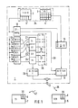
- the two devices 5 and 7 of the entertainment electronics are shown as device blocks and an associated remote control transmitter 1 as a block diagram.
- the devices 5 and 7 form with the remote control transmitter 1, a device system that can be operated remotely by the remote control transmitter 1.
- the remote control transmitter 1 contains two button groups 2 and 3 on a control panel 34.
- the first button group 2 comprises operating elements 4 for remote control of the first device 5 of the entertainment electronics, in the illustrated embodiment of a video recorder.
- the second button group 3 includes controls 6 for operating the second remotely controllable device 7 of entertainment electronics, in illustrated embodiment of a television receiver from a manufacturer other than the manufacturer of the video recorder 5. Accordingly, the remote control receiver parts 8 and 9 of the two devices 5 and 6 are components of different remote control systems.
- a system data memory and command code memory 10 is connected to the first button group 2, which contains both the command code and the system data of the remote control transmission system S0 of the video recorder 5 assigned to the remote control transmitter and the associated command code for an operating element 4 operated in the first button group 2 to a sequence control circuit 11 transmits and starts the program flow of this control circuit. From this, the sequence control circuit 11 generates the remote control signals 38 of the remote control transmission system S0, which is installed in the remote control receiving part 8 of the video recorder 5, and transmits these remote control signals in accordance with this remote control transmission system via a transmitter element 12 to a receiving element 35 of the two remotely controllable devices 5 and 7 of the entertainment electronics.
- the key elements 6 of the second key group 3 of the remote control transmitter 1 are connected to the inputs of a number of additional command code converters 13 to 18 and a transmission circuit 19.
- Each of these additional command code converters 13 to 18 contains a set of command codes BC2.2 to BC6 assigned to the operating elements 6 of the second key group 3.
- the individual command code converters 13 to 18 are assigned to additional system data memories 21 to 24.
- One of these system data memories contains the system data and the program sequence data of a specific remote control transmission system S1 to S4, which are required for the control of a second sequence control circuit 25 so that the second sequence control circuit 25 can form the remote control signals of the relevant remote control transmission system therefrom.
- the selection of which of the additional system data memories S1 to S4 and, if appropriate, which additional command code converter associated with the selected additional system data memory should cooperate with the second sequence control circuit 25 in a remote control circuit is made by a solder bridge 26 between the selection contacts 27 of a solder bridge arrangement 28.
- the additional system data memory 23 for the remote control transmission system S3 and the additional command code converter 13 with the command code set BC2.2 are activated with the second sequence control circuit 25 to form a remote control circuit.
- the transmission circuit 19 in the remote control transmitter is activated with a solder bridge in the solder bridge arrangement 28.
- the key signals of the operating elements operated in the second key group 3 are transferred circuit 19 transmitted directly to the system data memory and command code memory 10 for the remote control transmission system S0 of the video recorder 5.
- the program sequence in the sequence control circuit 11 is set via a connection 29 such that the remote control signals generated by the sequence control circuit 11 contain an address signal which only switches the remote control receiver part 9 of the television set 7 into effect.
- S1, S3 are assigned more than one additional command code converter. This is the case when consumer electronics devices work with the same remote control transmission system, but which, due to the different makes of the devices or the further development of the devices, contain tables with different command codes for the same commands.
- the solder bridge assembly 28 is covered and attached, for example, in the remote control transmitter 1 via the battery compartment. It serves to select the corresponding remote control circuit for the second key group 3 and to mark it with a solder bridge 26 and thus to set it.
- the additional system data memory 23 is marked with the command code converter 13 by the solder bridge 26, so that these two circuits form a remote control circuit with the second sequence control circuit 25, which generates the selected remote control signals of the command code BC2.2 in the desired remote control transmission system S3. Only one solder bridge may ever be made in the solder bridge arrangement 28.
- a slide switch can be used instead of a solder bridge arrangement.
- the remote control transmitter 1 shown in FIG. 2 differs from the remote control transmitter 1 shown in FIG. 1 essentially in that it contains only one sequence control circuit 25, that it also contains a system data memory 20 which is separate from the command code memory 10 and in which the program sequence data and system data of the remote control transmission system S0 of the video recorder 5 are stored, and that it contains, as a marking arrangement, an allocation memory 30 which contains an allocation memory location (31.1 to 31.7) for each marking location.
- the additional system data memory 23 assigned to this assignment memory location and the additional command code converter 13 assigned to this assignment memory location are activated to a remote control circuit, so that when one of the operating elements 6 or 4 of the key groups 2 or 3 is activated, the sequence control circuit 25, the marked command code converter 13 and the marked system data memory 23 remote control circuit formed is set in motion and the sequence control circuit 25 forms the corresponding remote control signal from the data of this remote control circuit.
- the operating elements TV0 and L or the second key group are actuated simultaneously for programming the allocator memory 30 and during the actuation of these two operating elements, the assigned memory location 31.5 is set by actuating a specific operating element of the first key group.
- the assignor memory 30 is a non-volatile memory, the programmed assignment of which is retained even when the battery on the remote control transmitter is changed and is only changed according to the program by a new setting.
- the two remote-controlled devices 5 and 7 shown in FIG. 2 are connected to one another by a cable 32, via which, when the video broadcast recorded on a video cassette 33 is played back, the video signals reach the television 7, on the screen 34 of which the video broadcast recorded on the video cassette 33 is reproduced becomes.
- the key group 3 provided for operating the television 7 contains only the keys which are absolutely necessary for operating the television 7 in cooperation with the video recorder 5.
- the control panel 34 of the remote control transmitter 1 remains clear for the user of the remote control transmitter.
- the command code memory 10 and the additional command code converters 13 to 18, the system data memory 20, the additional system data memory 21 to 24, the sequence control circuit 25 and the assignor memory 30 are components of a microprocessor in a particularly advantageous embodiment of the remote control transmitter shown in FIG. The same applies for the modules 13 to 25 of the exemplary embodiment of a remote control transmitter 1 shown in FIG. 1.
- the second sequence control circuit 25 and the additional system data memories and the additional command code converters are not in the remote control transmitter, but arranged in one of the devices of the entertainment electronics of the device system. This has the advantage that a larger amount of additional system data memories and additional command code converters can be accommodated.
- the second sequence control circuit 25, the additional command code converters 13 to 18 and the additional system data memories 21 to 24 and the assignment memory 30 are arranged in the video recorder 5.
- the associated remote control transmitter 1 contains a first keypad 2 with the operating elements 4 for remote control of the video recorder 5 and a second keypad 3 for operating the television set 7 in certain operating states required in connection with the video recorder.
- the remote control commands called up from the second keypad 3 receive an identification signal KS which is generated in the remote control circuit of the remote control transmitter 1 formed from the command code memory and system data memory 10 and the sequence control circuit 11.
- the remote control receiving part 8 of the video recorder 5 which separates the remote control commands from the wirelessly transmitted remote control signal, transmits the remote control commands called up with the first keypad 2 to a function control circuit 36 of the video recorder 5 for setting the corresponding video recorder functions.
- this remote control command reaches the signal input of the function control circuit 40 of the television 7 via a signal line 41 of a cable (not shown in more detail), which is thereby controlled into the desired operating state.
- the embodiment shown in Figure 4 of a device system containing two devices 5 and 7 of the entertainment electronics differs from the embodiment of a device system shown in Figure 3 essentially only in that the sequence control circuit 25 of the remote control circuit of the video recorder also formed from the marked command code converter and the marked system data memory 5 generates a remote control signal 42 at its output, the is wirelessly transmitted to the remote control receiving part 9 of the television 7.
- This remote control receiving part 9 transmits the remote control commands received with the remote control signal to the function control circuit 40 of the television 7 for setting the corresponding operating procedures or operating values of the television 7.
- the wireless transmission of the remote control signals between the two devices 5 and 7 of the entertainment electronics takes place either via a transmission element 43 which is mounted directly in the housing wall 44 of the video recorder 5 or via a transmission element 45 of a transmission device 46 which is connected to the video recorder 5 via a cable 47.
- the transmitting element 45 can be set most easily into the most favorable transmission position to the other device or to the other devices of the device system.
- the remote control transmitter 1 contains only a button group 2, or in an alternative embodiment of a remote control transmitter 1 'shown by an angular offset of a main axis 48 of the remote control transmitter 1' of a specific normal direction controlled command generator 49.
- the assignment of the key group 2 or the command generator 49 to the individual remote-controlled devices of the device system is determined by the user by actuating certain selection control elements 50.
- the actuated element of the selection controls 50 triggered in the command code memory and system data memory 10 of the remote control transmitter 1 or 1 'a corresponding identification signal KS1, KS2 or KS3, which identifies the device of the device system that just is operated remotely and is transmitted with the remote control command with the remote control signal 38 generated in the remote control transmitter to the remote control receiving part 8 of the video recorder 5 for further processing.
Abstract
Description
Die Erfindung betrifft ein Gerätesystem gemäß dem Oberbegriff des Anspruches 1.The invention relates to a device system according to the preamble of
In vielen Haushalten nimmt die Zahl derartiger drahtlos fernbedienbarer elektrischer Geräte immer weiter zu, wobei die Übertragungssysteme, über die diese Geräte fernbedienbar sind, so unterschiedlich sind, daß sie über unterschiedliche Fernbedienungsgeber fernbedient werden müssen. Damit wird die Anzahl der in einem Haushalt befindlichen Fernbedienungsgeber schnell so groß, daß die Zuordnung der Fernbedienungsgeber zu den einzelnen fernbedienbaren Geräten nicht mehr überschaubar ist. Hinzu kommt, daß bei der Benutzung von Geräten der Unterhaltungselektronik mehrere Geräte miteinander korrespondieren und ein Gerätesystem bilden, in dem diese Geräte nebeneinander bedient werden müssen. Ein derartiges Gerätesystem besteht beispielsweise bei der Wiedergabe einer Aufzeichnung eines Videobandes, bei der ein Videorecorder mit einem Fernsehgerät verbunden ist, und bei der beide Geräte zur Einstellung der Wiedergabe nebeneinander bedient werden müssen. Es ist zwar aus den Zeitschriften Funkschau 1985, Heft 18, Seiten 54 bis 58 und Funkschau 1986, Heft 14, Seiten 42 bis 44 bekannt, ein aus einem Fernsehgerät und einem Videorecorder gebildetes Gerätesystem eines Herstellers mit einem einzigen Fernbedienungsgeber zu betätigen. Sind jedoch die nebeneinander fernzubedienenden, miteinander kommunizierenden Geräte eines Gerätesystemes Geräte unterschiedlicher Fabrikate mit unterschiedlichen Übertragungssystemen für die Fernbedienung, muß jedes dieser Geräte mit dem ihm zugehörigen Fernbedienungsgeber oder direkt am Gerät an der Ortsbedienung entsprechend den Bedienungswünschen des Benutzers eingestellt werden.In many households the number of such wirelessly remotely controllable electrical devices continues to increase, the transmission systems via which these devices can be remotely controlled are so different that they have to be remotely operated via different remote control transmitters. The number of remote control transmitters in a household thus quickly becomes so large that the assignment of the remote control transmitters to the individual remote-controllable devices is no longer manageable. In addition, when using consumer electronics devices, several devices correspond to one another and form a device system in which these devices have to be operated side by side. Such a device system exists, for example, at Playback of a recording of a video tape in which a video recorder is connected to a television set and in which both devices have to be operated side by side in order to set the playback. It is known from the magazines Funkschau 1985,
Der Erfindung liegt deshalb die Aufgabe zugrunde, eine Möglichkeit zu schaffen, mit der wenigstens zwei in einem Gerätesystem zusammengefaßte und nebeneinander fernzubedienende elektrische Geräte der Unterhaltungselektronik unterschiedlicher Fernbedienungsübertragungssysteme dennoch mit einem einzigen Fernbedienungsgeber nebeneinander bedient werden können. Diese Aufgabe wird nach der Erfindung durch die im kennzeichnenden Teil des Anspruches 1 angegebenen Merkmale gelöst.The invention is therefore based on the object of creating a possibility with which at least two electrical devices of entertainment electronics of different remote control transmission systems which are combined in a device system and can be remote-controlled next to one another can nevertheless be operated side by side with a single remote control transmitter. This object is achieved according to the invention by the features specified in the characterizing part of
In einem Gerätesystem nach der Erfindung sind die gängigsten Fernbedienungsübertragungssysteme einprogrammiert. Damit ist ein aus mehreren handelsüblichen Geräten der Unterhaltungselektronik gebildetes Gerätesystem in einfacher Weise auf die Fernbedienung dieser Geräte mit nur einer Fernbedienung eingerichtet, auch dann, wenn diese Geräte mit unterschiedlichen, nicht kompatiblen Fernbedienungsübertragungssystemen arbeiten. Die Einstellung des Gerätesystems auf die Fernbedienung bestimmter, im Haushalt eines Benutzers befindlicher und zu einem Gerätsystem zusammengestellter handelsüblicher Geräte ist auch für den technisch weniger geübten Benutzer in einfacher Weise mit wenigen Handgriffen durchführbar.The most common remote control transmission systems are programmed into a device system according to the invention. A device system formed from a number of commercially available consumer electronics devices is thus set up in a simple manner for the remote control of these devices with only one remote control, even when these devices are used different, incompatible remote control transmission systems work. The setting of the device system for the remote control of certain commercial devices located in the household of a user and assembled into a device system can also be carried out in a simple manner for the less technically experienced user.
In einer vorteilhaften Ausgestaltung der Erfindung sind die für die einstellbare oder programmierbare Fernsteuerschaltung erforderlichen zusätzlichen Schaltungen und Speicher ausschließlich im Fernbedienungsgeber angeordnet. Damit ist die Einrichtung, Geräte mit unterschiedlichen Fernbedienungsübertragungssystemen fernzubedienen, ausschließlich im Fernbedienungsgeber angeordnet. In diesem Fall können alle handelsüblichen Geräte der Unterhaltungselektronik, deren Fernbedienungsübertragungssystem und Fernbedienungscode im Fernbedienungsgeber gespeichert ist, mit dem einen Fernbedienungsgeber des Gerätesystems fernbedient werden, sobald im Fernbedienungsgeber zusätzlich das entsprechende Fernbedienungsübertragungssystem und der entsprechende Fernbedienungscode wirksam geschaltet ist.In an advantageous embodiment of the invention, the additional circuits and memories required for the adjustable or programmable remote control circuit are arranged exclusively in the remote control transmitter. The device for remote control of devices with different remote control transmission systems is thus only arranged in the remote control transmitter. In this case, all commercially available consumer electronics devices, whose remote control transmission system and remote control code are stored in the remote control transmitter, can be operated remotely with the one remote control transmitter of the device system as soon as the corresponding remote control transmission system and the corresponding remote control code are also activated in the remote control transmitter.
Soll jedoch der Umfang der möglichen Auswahl der mit einem Fernbedienungsgeber fernzubedienenden handelsüblichen Geräte der Unterhaltungselektronik relativ groß sein, so daß der erforderliche Umfang der zusätzlichen Schaltungen nicht mehr in einem Fernbedienungsgehäuse untergebracht werden kann, sind in einer weiteren vorteilhaften Ausbildung der Erfindung diese zusätzlichen Schaltungen in einem der Geräte der Unterhaltungselektronik des Gerätesystemes untergebracht. Diesem Gerät ist dann der Fernbedienungsgeber des Gerätesystemes zugeordnet. Dieses Gerät wertet entsprechend einem zusätzlichen Kennungssignal zum Fernbedienungsbefehl die von ihm empfangenen Fernbedienungssignale selbst aus oder setzt sie in Befehle des voreingestellten Fernbedienungsübertragungssystems um und sendet sie draht gebunden oder drahtlos an die anderen Geräte der Unterhaltungselektronik des Gerätesystemes aus. Die anderen (Geräte des Gerätesystemes sind ebenfalls handelsübliche Geräte der Unterhaltungselektronik. Sie enthalten jedoch keine weiteren zusätzlichen Einrichtungen für die Fernbedienung anderer Geräte des Gerätesystems.However, if the scope of the possible selection of commercially available consumer electronics devices to be remote-controlled with a remote control transmitter is relatively large, so that the required scope of the additional circuits can no longer be accommodated in a remote control housing, these additional circuits are in a further advantageous embodiment of the invention housed in one of the devices of the entertainment electronics of the device system. The remote control transmitter of the device system is then assigned to this device. In accordance with an additional identification signal for the remote control command, this device evaluates the remote control signals received by it itself or converts them into commands of the preset remote control transmission system and sends them out in a wired or wireless manner to the other devices in the entertainment electronics of the device system. The other devices of the device system are also commercially available devices of entertainment electronics. However, they do not contain any additional devices for the remote control of other devices of the device system.
Die Anwahl der fernzubedienenden Geräte eines derartigen Gerätesystems erfolgt entweder über unterschiedliche Tastengruppen des Fernbedienungsgebers oder über zusätzlich auf dem Fernbedienungsgeber angeordnete besondere Bedienungselemente zur Auswahl des fernzubedienenden Gerätes der Unterhaltungselektronik.The selection of the devices of such a device system to be operated remotely takes place either via different key groups of the remote control transmitter or via special operating elements additionally arranged on the remote control transmitter for selecting the device of the entertainment electronics to be operated remotely.
Die vorgenannten und weitere vorteilhafte Ausgestaltungen der Erfindung sind in den Unteransprüchen angegeben. Insbesondere sind die Einstellelemente zur Einstellung des gewünschten Fernbedienungsübertragungssystemes so ausgestaltet, daß diese Einstellung zwar in einfacher Weise, aber bewußt und gezielt vorgenommen werden muß und nicht versehentlich durch eine Falschbedienung des Fernbedienungsgebers verändert werden kann.The aforementioned and further advantageous refinements of the invention are specified in the subclaims. In particular, the setting elements for setting the desired remote control transmission system are designed so that this setting must be carried out in a simple manner, but consciously and specifically and cannot be changed accidentally by incorrect operation of the remote control transmitter.
Die Erfindung wird nachfolgend anhand einiger vorteilhafter Ausführungsbeispiele näher erläutert. In der zugehörigen Zeichnung zeigen
- Fig. 1 und Fig. 2 je eine Blockdarstellung eines Gerätesystems mit zwei Geräten der Unterhaltungselektronik und einem diese Geräte steuernden, in Funktionsblöcken dargestellten Fernbedienungsgeber
- Fig. 3 und Fig. 4 je eine Blockdarstellung eines Gerätesystems mit zwei von einem Fernbedienungsgeber fernbedienbaren Geräten der Unterhaltungselektronik, von denen eines der beiden Geräte die vorprogrammierbare Fernsteuerschaltung für das andere Gerät enthält.
- 1 and 2 each show a block diagram of a device system with two devices of entertainment electronics and a remote control transmitter which controls these devices and is shown in function blocks
- 3 and 4 each show a block diagram of a device system with two consumer electronics devices that can be remote-controlled by a remote control transmitter, one of which contains the preprogrammable remote control circuit for the other device.
In Figur 1 sind die beiden Geräte 5 und 7 der Unterhaltungselektronik als Geräteblöcke und ein zugehöriger Fernbedienungsgeber 1 als Blockschaltbild dargestellt. Die Geräte 5 und 7 bilden mit dem Fernbedienungsgeber 1 ein Gerätesystem, das durch den Fernbedienungsgeber 1 fernbedient werden kann. Der Fernbedienungsgeber 1 enthält auf einem Bedienungsfeld 34 zwei Tastengruppen 2 und 3. Die erste Tastengruppe 2 umfaßt Bedienungselemente 4 zur Fernbedienung des ersten Gerätes 5 der Unterhaltungselektronik, im dargestellten Ausführungsbeispiel eines Videorecorders. Die zweite Tastengruppe 3 umfaßt Bedienungselemente 6 zur Bedienung des zweiten fernbedienbaren Gerätes 7 der Unterhaltungselektronik, im dargestellten Ausführungsbeispiel eines Fernsehempfängers eines anderen Herstellers als dem Hersteller des Videorecorders 5. Dementsprechend sind die Fernbedienungsempfangsteile 8 und 9 der beiden Geräte 5 und 6 Bestandteile unterschiedlicher Fernbedienungssysteme.In Figure 1, the two
An die erste Tastengruppe 2 ist ein Systemdatenspeicher und Befehlscodespeicher 10 angeschlossen, der sowohl den Befehlscode als auch die Systemdaten des Fernbedienungsübertragungssystems S0 des dem Fernbedienungsgeber zugeordneten Videorecorders 5 enthält und der für ein in der ersten Tastengruppe 2 betätigtes Bedienungselement 4 den zugehörigen Befehlscode an eine Ablaufsteuerschaltung 11 überträgt und den Programmablauf dieser Steuerschaltung in Gang setzt. Die Ablaufsteuerschaltung 11 erzeugt daraus die Fernbedienungssignale 38 des Fernbedienungsübertragungssystemes S0, das im Fernbedienungsempfangsteil 8 des Videorecorders 5 installiert ist, und überträgt diese Fernbedienungssignale entsprechend diesem Fernbedienungsübertragungssystem über ein Senderelement 12 an ein Empfangselement 35 der beiden fernbedienbaren Geräte 5 und 7 der Unterhaltungselektronik.A system data memory and
Die Tastenelemente 6 der zweiten Tastengruppe 3 des Fernbedienungsgebers 1 sind mit den Eingängen einer Reihe zusätzlicher Befehlscodewandler 13 bis 18 und einer Übertragungsschaltung 19 verbunden. Jeder dieser zusätzlichen Befehlscodewandler 13 bis 18 enthält einen den Bedienungselementen 6 der zweiten Tastengruppe 3 zugeordneten Satz von Befehlscodes BC2.2 bis BC6. Die einzelnen Befehlscodewandler 13 bis 18 sind zusätzlichen Systemdatenspeichern 21 bis 24 zugeordnet. Je einer dieser Systemdatenspeicher enthält die Systemdaten und die Programmablaufdaten eines bestimmten Fernbedienungsübertragungssystemes S1 bis S4, die für die Steuerung einer zweiten Ablaufsteuerschaltung 25 erforderlich sind, damit die zweite Ablaufsteuerschaltung 25 daraus die Fernbedienungssignale des betreffenden Fernbedienungsübertragungssystemes bilden kann. Die Auswahl, welcher der zusätzlichen Systemdatenspeicher S1 bis S4 und gegebenenfalls welcher dem ausgewählten zusätzlichen Systemdatenspeicher zugeordnete zusätzliche Befehlscodewandler mit der zweiten Ablaufsteuerschaltung 25 in einer Fernsteuerschaltung zusammenarbeiten soll, wird durch eine Lötbrücke 26 zwischen den Auswahlkontakten 27 einer Lötbrückenanordnung 28 getroffen. Im dargestellten Ausführungsbeispiel wird der zusätzliche Systemdatenspeicher 23 für das Fernbedienungsübertragungssystem S3 und der zusätzliche Befehlscodewandler 13 mit dem Befehlscodesatz BC2.2 mit der zweiten Ablaufsteuerschaltung 25 zu einer Fernsteuerschaltung wirksam geschaltet. Bei dieser Einstellung kann ein Benutzer des Fernbedienungsgebers nebeneinander mit nur einem einzigen Fernbedienungsgeber sowohl den fernbedienbaren Videorecorder 5 als auch den fernbedienbaren Fernseher 7 entsprechend seinen Wünschen fernbedienen.The
Arbeitet der Fernbedienempfänger 9 des Fernsehgerätes 7 nach dem gleichen Fernbedienungsübertragungssystem S0 wie das Fernbedienungsempfangsteil 8 des Videorecorders 5 und sollen beide Geräte mit dem gleichen Fernbedienungsgeber bedient werden, dann wird die Übertragungsschaltung 19 in dem Fernbedienungsgeber mit einer Lötbrücke in der Lötbrückenanordnung 28 wirksam geschaltet. In diesem Fall werden die Tastensignale der in der zweiten Tastengruppe 3 bedienten Bedienungselemente von der Übertragungs schaltung 19 unmittelbar an den Systemdatenspeicher und Befehlscodespeicher 10 für das Fernbedienungsübertragungssystem S0 des Videorecorders 5 übertragen. Außerdem wird über eine Verbindung 29 der Programmablauf in der Ablaufsteuerschaltung 11 so eingestellt, daß die von der Ablaufsteuerschaltung 11 erzeugten Fernbedienungssignale ein Adressensignal enthalten, das nur den Fernbedienungsempfangsteil 9 des Fernsehgerätes 7 wirksam schaltet.If the
Einigen zusätzlichen Systemdatenspeichern (S1, S3) sind mehr als ein zusätzlicher Befehlscodewandler zugeordnet. Dies ist dann der Fall, wenn Geräte der Unterhaltungselektronik mit dem gleichen Fernbedienungsübertragungssystem arbeiten, die jedoch infolge der unterschiedlichen Fabrikate der Geräte oder der Weiterentwicklung der Geräte Tabellen mit unterschiedlichen Befehlscodes für die gleichen Befehle enthalten.Some additional system data memories (S1, S3) are assigned more than one additional command code converter. This is the case when consumer electronics devices work with the same remote control transmission system, but which, due to the different makes of the devices or the further development of the devices, contain tables with different command codes for the same commands.
Die Lötbrückanordnung 28 ist verdeckt und beispielsweise ber das Batteriefach zugänglich im Fernbedienungsgeber 1 angebracht. Sie dient dazu, für die zweite Tastengruppe 3 die entsprechende Fernsteuerschaltung auszuwählen und mit einer Lötbrücke 26 zu markieren und damit einzustellen. Im dargestellten Ausführungsbeispiel ist durch die Lötbrücke 26 der zusätzliche Systemdatenspeicher 23 mit dem Befehlscodewandler 13 markiert, so daß diese beiden Schaltungen mit der zweiten Ablaufsteuerschaltung 25 eine Fernsteuerschaltung bilden, die die ausgewählten Fernbedienungssignale des Befehlscodes BC2.2 im gewünschten Fernbedienungsübertragungssystem S3 erzeugt. In der Lötbrückenanordnung 28 darf immer nur eine Lötbrücke hergestellt sein. In einem anderen Ausführungsbeispiel des Fernbedienungsgebers kann als Markierungsanordnung anstelle einer Lötbrückenanordnung ein Schiebeschalter verwendet werden.The
Bei dem in Figur 2 dargestellten Ausführungsbeispiel eines Gerätesystems sind für die mit dem in Figur 1 dargestellten Ausführungsbeispiel übereinstimmenden Schaltungsblöcke die gleichen Bezugszeichen verwendet. Der in Figur 2 dargestellte Ferrnbedienungsgeber 1 unterscheidet sich von dem in Figur 1 dargestellten Fernbedienungsgeber 1 im wesentlichen darin, daß er nur eine Ablaufsteuerschaltung 25 enthält, daß er außerdem einen vom Befehlscodespeicher 10 getrennten Systemdatenspeicher 20 enthält, in dem die Programmablaufdaten und Systemdaten des Fernbedienungsübertragungssystems S0 des Videorecorders 5 gespeichert sind, und daß er als Markierungsanordnung einen Zuordnerspeicher 30 enthält, der für jede Markierungsstelle eine Zuordnerspeicherstelle (31.1 bis 31.7) enthält. Mit einer markierten Zuordnerspeicherstelle (31.5) wird der dieser Zuordnerspeicherstelle zugeordnete zusätzliche Systemdatenspeicher 23 und der dieser Zuordnerspeicherstelle zugeordnete zusätzliche Befehlscodewandler 13 zu einer Fernsteuerschaltung wirksam geschaltet, so daß beim Betätigen eines der Bedienungselemente 6 oder 4 der Tastengruppen 2 oder 3 die aus der Ablaufsteuerschaltung 25, dem markierten Befehlscodewandler 13 und dem markierten Systemdatenspeicher 23 gebildete Fernsteuerschaltung in Gang gesetzt wird und die Ablaufsteuerschaltung 25 aus den Daten dieser Fernsteuerschaltung das entsprechende Fernbedienungssignal bildet.In the exemplary embodiment of a device system shown in FIG. 2, the same reference numerals are used for the circuit blocks corresponding to the exemplary embodiment shown in FIG. The
Zur Programmierung des Zuordnerspeichers 30 werden im dargestellten Ausführungsbeispiel die Bedienungselemente TV0 und Lder zweiten Tastengruppe gleichzeitig betätigt und während der Betätigung dieser beiden Bedienungselemente die zu markierende Zuordnerspeicherstelle 31.5 durch Betätigen eines bestimmten Bedienungselementes der ersten Tastengruppe gesetzt. Für diese Art der Programmierung sind somit keine zusätzlichen Einstellelemente auf dem Fernbedienungsgeber erforderlich. Der Zuordnerspeicher 30 ist im dargestellten Ausführungsbeispiel ein nicht flüchtiger Speicher, dessen programmierte Zuordnung auch bei einem Batteriewechsel am Fernbedienungsgeber erhalten bleibt und nur durch eine neue Einstellung entsprechend des Programmes geändert wird.In the exemplary embodiment shown, the operating elements TV0 and L or the second key group are actuated simultaneously for programming the
Die beiden in Figur 2 dargestellten fernbedienbaren Geräte 5 und 7 sind durch ein Kabel 32 miteinander verbunden, über das bei einer Wiedergabe der auf einer Videocassette 33 aufgezeichneten Videosendung die Videosignale zum Fernseher 7 gelangen, auf dessen Bildschirm 34 die auf der Videocassette 33 aufgezeichnete Videosendung wiedergegeben wird. Im Ausführungsbeispiel der Figur 2 enthält die für die Bedienung des Fernsehers 7 vorgesehene Tastengruppe 3 nur die für eine Bedienung des Fernsehgerätes 7 im Zusammenwirken mit dem Videorecorder 5 unbedingt notwendigen Tasten. Dadurch bleibt das Bedienungsfeld 34 des Fernbedienungsgebers 1 für den Benutzer des Fernbedienungsgebers übersichtlich.The two remote-controlled
Der Befehlscodespeicher 10 und die zusätzlichen Befehlscodewandler 13 bis 18, der Systemdatenspeicher 20, die zusätzlichen Systemdatenspeicher 21 bis 24, die Ablaufsteuerschaltung 25 und der Zuordnerspeicher 30 sind in einem besonders vorteilhaften Ausführungsbeispiel des in Figur 2 dargestellten Fernbedienungsgebers Bestandteile eines Mikroprozessors. Entsprechendes gilt für die Baugruppen 13 bis 25 des in Figur 1 dargestellten Ausführungsbeispieles eines Fernbedienungsgebers 1.The
Bei den in den Figuren 3 und 4 in Geräteblöcken und Funktionsblöcken dargestellten Ausführungsbeispielen eines aus zwei Geräten 5 und 7 der Unterhaltungselektronik und einem für die Fernbedienung vorgesehenen Fernbedienungsgeber 1 bestehenden Gerätesystem sind die zweite Ablaufsteuerschaltung 25 und die zusätzlichen Systemdatenspeicher und die zusätzlichen Befehlscodewandler nicht im Fernbedienungsgeber, sondern in einem der Geräte der Unterhaltungselektronik des Gerätesystems angeordnet. Dies hat den Vorteil, daß ein größerer Umfang an zusätzlichen Systemdatenspeichern und zusätzlichen Befehlscodewandlern untergebracht werden kann.In the exemplary embodiments shown in FIGS. 3 and 4 in device blocks and functional blocks of a device system consisting of two
Bei dem in Figur 3 dargestellten Ausführungsbeispiel eines derartigen Gerätesystems sind die zweite Ablaufsteuerschaltung 25, die zusätzlichen Befehlscodewandler 13 bis 18 und die zusätzlichen Systemdatenspeicher 21 bis 24 und der Zuordnerspeicher 30 im Videorecorder 5 angeordnet. Der zugehörige Fernbedienungsgeber 1 enthält ein erstes Tastenfeld 2 mit den Bedienungselementen 4 zur Fernbedienung des Videorecorders 5 und ein zweites Tastenfeld 3 zur Bedienung des Fernsehgerätes 7 in bestimmten, im Verbund mit dem Videorecorder erforderlichen Betriebszuständen. Zur Unterscheidung, welches der beiden Geräte 5 oder 7 gerade fernbedient wird, erhalten die vom zweiten Tastenfeld 3 abgerufenen Fernbedienungsbefehle ein Kennungssignal KS, das in der aus dem Befehlscodespeicher und Systemdatenspeicher 10 und der Ablaufsteuerschaltung 11 gebildeten Fernsteuerschaltung des Fernbedienungsgebers 1 erzeugt wird.In the exemplary embodiment of such a device system shown in FIG. 3, the second
Das Fernbedienungsempfangsteil 8 des Videorecorders 5, das die Fernbedienungsbefehle aus dem drahtlos übertragenen Fernbedienungssignal trennt, überträgt die mit dem ersten Tastenfeld 2 abgerufenen Fernbedienungsbefehle an eine Funktionssteuerschaltung 36 des Videorecorders 5 zur Einstellung der entsprechenden Videorecorderfunktionen. Die über die Bedienungselemente 6 des zweiten Tastenfeldes 3 des Fernbedienungsgebers 1 abgerufenen Fernbedienungssignale für den Fernseher 7 gelangen von einen Signalausgang 37 des Fernbedienungsempfangsteils 8 des Videorecorders an die Eingänge der zusätzlichen Befehlscodewandler 13 bis 18 und lösen an dem über dem Zuordnerspeicher 30 markierten Befehlscodewandler einen Befehlscode aus, der dem aufgerufenen Fernbedienungsbefehl für den Fernseher 7 entspricht und der am Signalausgang 39 der Ablaufsteuerschaltung 25 einen für die Funktionssteuerschaltung 40 des Fernsehers verständlichen Fernsteuerbefehl mit dem gewünschten Befehlsinhalt erzeugt. Dieser Fernsteuerbefehl gelangt in dem dargestellten Ausführungsbeispiel über eine Signalleitung 41 eines nicht näher dargestellten Kabels an den Signaleingang der Funktionssteuerschaltung 40 des Fernsehers 7, der dadurch in den gewünschten Betriebszustand gesteuert wird.The remote
Das in Figur 4 dargestellte Ausführungsbeispiel eines zwei Geräte 5 und 7 der Unterhaltungselektronik enthaltenden Gerätesystems unterscheidet sich von dem in Figur 3 dargestellten Ausführungsbeispiel eines Gerätesystems im wesentlichen nur dadurch, daß die Ablaufsteuerschaltung 25 der außerdem aus dem markierten Befehlscodewandler und dem markierten Systemdatenspeicher gebildeten Fernsteuerschaltung des Videorecorders 5 an ihrem Ausgang ein Fernbedienungssignal 42 erzeugt, das drahtlos an das Fernbedienungsempfangsteil 9 des Fernsehers 7 übertragen wird. Dieses Fernbedienungsempfangsteil 9 überträgt die mit dem Fernbedienungssignal empfangenen Fernbedienungsbefehle an die Funktionssteuerschaltung 40 des Fernsehers 7 zur Einstellung der entsprechenden Betriebsabläufe oder Betriebswerte des Fernsehers 7. Die drahtlose Übertragung der Fernbedienungssignale zwischen den beiden Geräten 5 und 7 der Unterhaltungselektronik erfolgt entweder über ein Sendeelement 43, das unmittelbar in der Gehäusewand 44 des Videorecorders 5 angebracht ist oder über ein Sendeelement 45 einer Sendeeinrichtung 46, die über ein Kabel 47 mit dem Videorecorder 5 verbunden ist. Im letzteren Fall kann das Sendeelement 45 am leichtesten in die günstigste Übertragungsposition zum anderen Gerät oder zu den anderen Geräten des Gerätesystems eingestellt werden.The embodiment shown in Figure 4 of a device system containing two
Bei dem in Figur 4 dargestellten Ausführungsbeispiel enthält der Fernbedienungsgeber 1, mit dem die Geräte 5 und 7 fernbedient werden, nur eine Tastengruppe 2, oder in einem alternativ dazu dargestellten Ausführungsbeispiel eines Fernbedienungsgeber 1′ einen mittels der Winkelablage einer Hauptachse 48 des Fernbedienungsgebers 1′ von einer bestimmten Normalrichtung gesteuerten Befehlsgeber 49. Die Zuordnung der Tastengruppe 2 oder des Befehlsgebers 49 zu den einzelnen fernzubedienenden Geräten des Gerätesystems wird vom Benutzer durch Betätigen bestimmter Auswahlbedienungselemente 50 bestimmt. Das betätigte Element der Auswahlbedienungselemente 50 lösten im Befehlscodespeicher und Systemdatenspeicher 10 des Fernbedienungsgebers 1 beziehungsweise 1′ ein entsprechendes Kennungssignal KS1, KS2 oder KS3 aus, das das Gerät des Gerätesystems kennzeichnet, das gerade fernbedient wird und das mit dem Fernbedienungsbefehl mit dem im Fernbedienungsgeber erzeugten Fernbedienungssignal 38 an das Fernbedienungsempfangsteil 8 des Videorecorders 5 zur Weiterverarbeitung übertragen wird.In the embodiment shown in Figure 4, the
Claims (9)
dadurch gekennzeichnet,
- daß wenigstens einer der zuordenbaren Tastengruppen (2, 3) mehrere zusätzliche Systemdatenspeicher (21 bis 24) zugeordnet sind, von denen jeder die Programmablaufdaten und Speicherdaten eines Fernbedienungsübertragungssystems voneinander verschiedender Fernbedienungsübertragungssysteme (51 bis 54) enthält,
- daß dieser Tastengruppe (3) bzw. diesen Tastengruppen mehrere zusätzliche Befehlscodewandler (13 bis 18) zugeordnet sind,
- daß ein Zuordenspeicher (28,30) markierbare Zuordnungselemente (27, 31) enthält, von denen jedes einem Systemdatenspeicher und/oder einem Befehlscodewandler zugeordnet ist und von denen ein bestimmtes, ausgewähltes Zuordnungselement (27, 31,5) durch ein Markierelement (26) markiert ist,
- und daß mittels des durch das Markierungselement markierten Zuordnungselementes der diesem zugeordnete Systemdatenspeicher (23) und der diesem zugeordnete Befehlscodewandler (13) mit einer Ablaufsteuerschaltung (25) zur Erzeugung von Fernbedienungssignalen (38, 42) zu einer Fernsteuerschaltung wirksam geschaltet ist.1. Device system consisting of at least two wirelessly remote-controlled electrical devices of the entertainment electronics and a remote control transmitter for wireless remote control of these devices by means of a button group of the remote control transmitter that can be assigned to each of these devices, with a remote control circuit that can be started by operating elements of the button group to form a remote control signal that can be transmitted via a transmission element, which contains a remote control command triggered via an operating element of the key group in a command code memory,
characterized,
- that at least one of the assignable key groups (2, 3) is assigned a plurality of additional system data memories (21 to 24), each of which contains the program sequence data and memory data of a remote control transmission system of different remote control transmission systems (51 to 54),
- That this key group (3) or these key groups are assigned several additional command code converters (13 to 18),
- That an allocation memory (28,30) contains markable allocation elements (27, 31), each of which is assigned to a system data memory and / or a command code converter and of which a specific, selected allocation element (27, 31,5) by a marking element (26 ) is marked,
- And that by means of the marking element marked by the marking element, the associated system data memory (23) and the associated command code converter (13) with a sequence control circuit (25) for generating remote control signals (38, 42) is activated to a remote control circuit.
- daß die Fernbedienungsbefehle, die in den Fernbedienungssignalen (38) der Fernbedienung (1) enthalten sind und einem der zusätzlichen Befehlscodewandler zugeordnet sind, eine Zuordnungskennung (KS) enthalten - und daß der Fernbedienungsempfänger die mit einer Zuordnungskennung versehenen Fernbedienungsbefehle an den markierten Befehlscodewandler (13) überträgt, der die Ablaufsteuerschaltung (25) zusammen mit dem durch das markierte Zuordnungselement (31.5) des Zuordnungsspeichers (30) markierten Systemdatenspeicher (23) zur Bildung entsprechender über ein Sendeelement (43) an das andere Gerät (7) oder eines der anderen Geräte des Gerätesystems übertragbarer Fernbedienungssignale (42) wirksam schaltet.4. Device system according to claim 1, characterized in that at least the remote control receiver (8) one of the devices (5) of the device system, the additional command code converters (13 to 18) are connected downstream and this device, the additional system data memory (21 to 28), the allocation memory ( 30) and the sequence control circuit (25) with which the marked additional storage is activated, contains
- That the remote control commands, which are contained in the remote control signals (38) of the remote control (1) and are assigned to one of the additional command code converters, contain an assignment identifier (KS) - and that the remote control receiver provides the assigned remote control commands to the marked command code converter (13 ) which transmits the sequence control circuit (25) together with the system data memory (23) marked by the marked assignment element (31.5) of the assignment memory (30) to form corresponding ones via a transmission element (43) to the other device (7) or one of the other devices of the device system of transmissible remote control signals (42).
Applications Claiming Priority (4)
| Application Number | Priority Date | Filing Date | Title |
|---|---|---|---|
| DE3821751 | 1988-06-28 | ||
| DE3821751 | 1988-06-28 | ||
| DE3918578 | 1989-06-07 | ||
| DE19893918578 DE3918578A1 (en) | 1988-06-28 | 1989-06-07 | DEVICE SYSTEM FROM AT LEAST TWO WIRELESS REMOTE CONTROLLED DEVICES OF ENTERTAINMENT ELECTRONICS |
Publications (2)
| Publication Number | Publication Date |
|---|---|
| EP0348774A2 true EP0348774A2 (en) | 1990-01-03 |
| EP0348774A3 EP0348774A3 (en) | 1991-05-08 |
Family
ID=25869524
Family Applications (1)
| Application Number | Title | Priority Date | Filing Date |
|---|---|---|---|
| EP19890111064 Withdrawn EP0348774A3 (en) | 1988-06-28 | 1989-06-19 | System consisting of at least two remotely controlled entertainment electronic devices |
Country Status (3)
| Country | Link |
|---|---|
| EP (1) | EP0348774A3 (en) |
| JP (1) | JPH0297195A (en) |
| DE (1) | DE3918578A1 (en) |
Families Citing this family (1)
| Publication number | Priority date | Publication date | Assignee | Title |
|---|---|---|---|---|
| JP3193176B2 (en) * | 1993-03-05 | 2001-07-30 | パイオニア株式会社 | Two-way remote control system |
Citations (9)
| Publication number | Priority date | Publication date | Assignee | Title |
|---|---|---|---|---|
| JPS59171397A (en) * | 1983-03-18 | 1984-09-27 | Sony Corp | Remote control device |
| JPS59171398A (en) * | 1983-03-18 | 1984-09-27 | Sony Corp | Remote control command device |
| US4623887A (en) * | 1984-05-15 | 1986-11-18 | General Electric Company | Reconfigurable remote control |
| EP0203668A2 (en) * | 1985-05-30 | 1986-12-03 | North American Philips Corporation | Universal remote control unit |
| GB2183069A (en) * | 1985-11-14 | 1987-05-28 | Sony Corp | Control systems |
| GB2191643A (en) * | 1986-06-02 | 1987-12-16 | Sony Corp | Remote control systems |
| JPS632499A (en) * | 1986-06-20 | 1988-01-07 | Mitsubishi Electric Corp | Euniversal remote control transmitter |
| JPS6314576A (en) * | 1986-07-07 | 1988-01-21 | Nec Corp | Remote controller |
| GB2197104A (en) * | 1986-10-24 | 1988-05-11 | Sony Corp | Remotely-controllable electronic apparatus including video systems |
-
1989
- 1989-06-07 DE DE19893918578 patent/DE3918578A1/en not_active Withdrawn
- 1989-06-19 EP EP19890111064 patent/EP0348774A3/en not_active Withdrawn
- 1989-06-28 JP JP16649189A patent/JPH0297195A/en active Granted
Patent Citations (9)
| Publication number | Priority date | Publication date | Assignee | Title |
|---|---|---|---|---|
| JPS59171397A (en) * | 1983-03-18 | 1984-09-27 | Sony Corp | Remote control device |
| JPS59171398A (en) * | 1983-03-18 | 1984-09-27 | Sony Corp | Remote control command device |
| US4623887A (en) * | 1984-05-15 | 1986-11-18 | General Electric Company | Reconfigurable remote control |
| EP0203668A2 (en) * | 1985-05-30 | 1986-12-03 | North American Philips Corporation | Universal remote control unit |
| GB2183069A (en) * | 1985-11-14 | 1987-05-28 | Sony Corp | Control systems |
| GB2191643A (en) * | 1986-06-02 | 1987-12-16 | Sony Corp | Remote control systems |
| JPS632499A (en) * | 1986-06-20 | 1988-01-07 | Mitsubishi Electric Corp | Euniversal remote control transmitter |
| JPS6314576A (en) * | 1986-07-07 | 1988-01-21 | Nec Corp | Remote controller |
| GB2197104A (en) * | 1986-10-24 | 1988-05-11 | Sony Corp | Remotely-controllable electronic apparatus including video systems |
Non-Patent Citations (4)
| Title |
|---|
| PATENT ABSTRACTS OF JAPAN vol. 12, no. 204 (E-620) 11 Juni 1988, & JP-A-63 002499 (MITSUBISHI ELECTRIC CORP.) 07 Januar 1988, * |
| PATENT ABSTRACTS OF JAPAN vol. 12, no. 221 (E-625) 23 Juni 1988, & JP-A-63 014576 (NEC CORP.) 21 Januar 1988, * |
| PATENT ABSTRACTS OF JAPAN vol. 9, no. 27 (E-294)(1750) 06 Februar 1985, & JP-A-59 171397 (SONY) 27 September 1984, * |
| PATENT ABSTRACTS OF JAPAN vol. 9, no. 27 (E-294)(1750) 06 Februar 1985, & JP-A-59 171398 (SONY) 27 September 1984, * |
Also Published As
| Publication number | Publication date |
|---|---|
| JPH0297195A (en) | 1990-04-09 |
| EP0348774A3 (en) | 1991-05-08 |
| JPH0557800B2 (en) | 1993-08-24 |
| DE3918578A1 (en) | 1990-01-11 |
Similar Documents
| Publication | Publication Date | Title |
|---|---|---|
| EP0348726A2 (en) | Remote control arrangement | |
| EP0780990B1 (en) | Method and apparatus for remote control of electronic equipment | |
| DE4407319B4 (en) | Remote control method | |
| DE3228354C2 (en) | User-guided operation of entertainment electronics devices | |
| DE3305090C3 (en) | Device for remote control of a video tape recorder and a television receiver connected to it | |
| EP0354459B1 (en) | Televison receiver | |
| DE3815560C2 (en) | ||
| EP0112589B1 (en) | Device for the programmed control of a radio or television reception device | |
| DE3131357C2 (en) | ||
| DE69034201T2 (en) | Tuning controller with possibility of vote by means of labels | |
| EP0002434A1 (en) | Remote control for the controlling and switching and the commuting of functions and of control magnitudes in telecommunication equipment | |
| DE4317313A1 (en) | Television receiver remote control unit - has buttons and knob with rotary encoder for setting audio volume, channel selection, screen position etc. | |
| DE3921847A1 (en) | DEVICE FOR CHOOSING A PROGRAM BY TELETEXTABLE | |
| DE2838104A1 (en) | MEMORY CIRCUIT FOR A TUNER | |
| EP0346614A2 (en) | Method of initialising a digital signal transmission system | |
| EP0413225B1 (en) | Electric time-controlled combination lock for protection against unauthorized use | |
| EP0489093B1 (en) | Remote control system | |
| DE69837172T2 (en) | Remote control and signal transmission device | |
| EP0447934B1 (en) | Method for entering switching related customer and operational data into communication exchanges and/or programmable communication terminals | |
| EP0348774A2 (en) | System consisting of at least two remotely controlled entertainment electronic devices | |
| DE4025999C2 (en) | ||
| DE4021482C2 (en) | Operating device for an audio device with several sound signal sources | |
| DE3817621A1 (en) | Remote control system with a battery-fed or accumulator-fed remote control unit | |
| EP0181537B1 (en) | Arrangement for an electronic entertainment apparatus with an adjustable control circuit operable from a plurality of different positions | |
| EP0881115B1 (en) | Seat adjusting device and car radio. |
Legal Events
| Date | Code | Title | Description |
|---|---|---|---|
| PUAI | Public reference made under article 153(3) epc to a published international application that has entered the european phase |
Free format text: ORIGINAL CODE: 0009012 |
|
| AK | Designated contracting states |
Kind code of ref document: A2 Designated state(s): AT BE DE ES FR GB IT LU NL |
|
| PUAL | Search report despatched |
Free format text: ORIGINAL CODE: 0009013 |
|
| RHK1 | Main classification (correction) |
Ipc: H04B 1/20 |
|
| AK | Designated contracting states |
Kind code of ref document: A3 Designated state(s): AT BE DE ES FR GB IT LU NL |
|
| STAA | Information on the status of an ep patent application or granted ep patent |
Free format text: STATUS: THE APPLICATION IS DEEMED TO BE WITHDRAWN |
|
| 18D | Application deemed to be withdrawn |
Effective date: 19911109 |