EP0349466A2 - Improvements in the manufacturing of transmission belts - Google Patents
Improvements in the manufacturing of transmission belts Download PDFInfo
- Publication number
- EP0349466A2 EP0349466A2 EP89500067A EP89500067A EP0349466A2 EP 0349466 A2 EP0349466 A2 EP 0349466A2 EP 89500067 A EP89500067 A EP 89500067A EP 89500067 A EP89500067 A EP 89500067A EP 0349466 A2 EP0349466 A2 EP 0349466A2
- Authority
- EP
- European Patent Office
- Prior art keywords
- mould
- belts
- transmi
- ssion
- manufacture
- Prior art date
- Legal status (The legal status is an assumption and is not a legal conclusion. Google has not performed a legal analysis and makes no representation as to the accuracy of the status listed.)
- Withdrawn
Links
Images
Classifications
-
- B—PERFORMING OPERATIONS; TRANSPORTING
- B29—WORKING OF PLASTICS; WORKING OF SUBSTANCES IN A PLASTIC STATE IN GENERAL
- B29D—PRODUCING PARTICULAR ARTICLES FROM PLASTICS OR FROM SUBSTANCES IN A PLASTIC STATE
- B29D29/00—Producing belts or bands
-
- B—PERFORMING OPERATIONS; TRANSPORTING
- B29—WORKING OF PLASTICS; WORKING OF SUBSTANCES IN A PLASTIC STATE IN GENERAL
- B29C—SHAPING OR JOINING OF PLASTICS; SHAPING OF MATERIAL IN A PLASTIC STATE, NOT OTHERWISE PROVIDED FOR; AFTER-TREATMENT OF THE SHAPED PRODUCTS, e.g. REPAIRING
- B29C37/00—Component parts, details, accessories or auxiliary operations, not covered by group B29C33/00 or B29C35/00
- B29C37/0053—Moulding articles characterised by the shape of the surface, e.g. ribs, high polish
-
- B—PERFORMING OPERATIONS; TRANSPORTING
- B29—WORKING OF PLASTICS; WORKING OF SUBSTANCES IN A PLASTIC STATE IN GENERAL
- B29C—SHAPING OR JOINING OF PLASTICS; SHAPING OF MATERIAL IN A PLASTIC STATE, NOT OTHERWISE PROVIDED FOR; AFTER-TREATMENT OF THE SHAPED PRODUCTS, e.g. REPAIRING
- B29C41/00—Shaping by coating a mould, core or other substrate, i.e. by depositing material and stripping-off the shaped article; Apparatus therefor
- B29C41/02—Shaping by coating a mould, core or other substrate, i.e. by depositing material and stripping-off the shaped article; Apparatus therefor for making articles of definite length, i.e. discrete articles
- B29C41/04—Rotational or centrifugal casting, i.e. coating the inside of a mould by rotating the mould
- B29C41/042—Rotational or centrifugal casting, i.e. coating the inside of a mould by rotating the mould by rotating a mould around its axis of symmetry
-
- B—PERFORMING OPERATIONS; TRANSPORTING
- B29—WORKING OF PLASTICS; WORKING OF SUBSTANCES IN A PLASTIC STATE IN GENERAL
- B29K—INDEXING SCHEME ASSOCIATED WITH SUBCLASSES B29B, B29C OR B29D, RELATING TO MOULDING MATERIALS OR TO MATERIALS FOR MOULDS, REINFORCEMENTS, FILLERS OR PREFORMED PARTS, e.g. INSERTS
- B29K2075/00—Use of PU, i.e. polyureas or polyurethanes or derivatives thereof, as moulding material
Definitions
- the patent refers to transmission belts and more particularly to belts made of polyurethane elastomer materials or similar, which are advantageously, from the quality point of view, replacing the traditional belts made of cloth-reinforced rubber.
- Polyurethane elastomer belts even in spite of their more extensive technical characterists than those of reinforced rubber, are not widely used in industry because of their high cost, which is derived almost essentially from their manufacturing process.
- elastomer belts were manufactured in closed moulds under pressure and heat, to finally form lengthy strips of finished material of a certain length. For use, the said lengths are usually cut to the required measurements and their free ends are welded to adopt the characteristic ring shape, all of which is a laborious process which directly affects their cost, as stated earlier.
- a basic aim of the patent is to constitute a manufacturing process for belts and similar parts using polyurethane elastomers, which notably simplify theteleonal systems, providing closed moulded units in one, single operation.
- the patent provides a hollow, cylindrical, rotary mould which is open on one of its faces and with its inner side surface equipped with grooves with a section corresponding to the section of the belt that it is wished to obtain.
- the mould is connected by its closed face, and by means of a shaft, to a transmitter of turning movement for the said mould, fitted with the corresponding coupling, so that the whole of the said mould assembly can be rotated.
- the inner side surface of the mould is furrowed, preferably, by a series of grooves, so that a set of belts can be produced in one, single operation, and the open front of the said mould shows a small, circular skirt, like a circular crown, whose purpose will be explained later.
- the polyurethane material is placed inside the mould in the exact, sufficient quantity as to provide the number of belts desired, so that in this first casting operation, the liquid polyurethane is controlled by the previously mentioned perimetral skirt.
- the mould is given rotary movement, thanks to which the liquid is projected towards the inner periphery where the grooves are situated.
- the mould-drum is stopped, so that a closed assembly made up of a series of properly finished belt units has been obtained.
- This heating is usually of between 40 and 80 degrees Centigrade.
- the mould-drum assembly (1) with one closed face (3) and one open face (6).
- the shaft (2) which is connected by means of a transmission (not shown) to another driving shaft which makes the mould (1) rotate.
- the open face (6) is equipped with the perimetral skirt (5), of suitable height, and the inner side surface (4) of the mould is furrowed with a series of grooves (7) with suitable shape to correspond to that of the belts to be finally produced.
- the plastic (10) is poured inside the mould, so that in this first operation, the said cast material is kept in position by the perimetral skirt (5).
- the mould (1) is made to rotate, with which the plastic (10), due to the centrifu gal force, reaches all the side surface (4) in which the grooves (7) are contained, appropriately adjusting itself to the said surface and occupying the recesses (9) in it.
- the assembly takes on a configuration as shown graphically in figure 4.
- the already set plastic material occupies the insides (11)-(12)-(13).... etc. of the grooves in the side (4) of the mould up to a height (10a), for example. Rotation of the mould is stopped at this moment and demoulding is started to obtain an assembly made up of a series of circular units which can be cut along the line indicated by the dots (14) in order to provide the desired belt.
- the number of grooves (7) in a specific mould can be variable, as can their section, which will be adjusted to the needs and specific shape of the belt to be made.
- passages (15) can be fitted, in which means will be arranged responsible for separating the already set belt from the mould so it can be extracted.
Abstract
Description
- The patent refers to transmission belts and more particularly to belts made of polyurethane elastomer materials or similar, which are advantageously, from the quality point of view, replacing the traditional belts made of cloth-reinforced rubber.
- Polyurethane elastomer belts, even in spite of their more extensive technical characterists than those of reinforced rubber, are not widely used in industry because of their high cost, which is derived almost essentially from their manufacturing process. Until now, elastomer belts were manufactured in closed moulds under pressure and heat, to finally form lengthy strips of finished material of a certain length. For use, the said lengths are usually cut to the required measurements and their free ends are welded to adopt the characteristic ring shape, all of which is a laborious process which directly affects their cost, as stated earlier.
- A basic aim of the patent is to constitute a manufacturing process for belts and similar parts using polyurethane elastomers, which notably simplify the traditional systems, providing closed moulded units in one, single operation.
- To put these objectives into practice, the patent provides a hollow, cylindrical, rotary mould which is open on one of its faces and with its inner side surface equipped with grooves with a section corresponding to the section of the belt that it is wished to obtain.
- The mould is connected by its closed face, and by means of a shaft, to a transmitter of turning movement for the said mould, fitted with the corresponding coupling, so that the whole of the said mould assembly can be rotated.
- The inner side surface of the mould is furrowed, preferably, by a series of grooves, so that a set of belts can be produced in one, single operation, and the open front of the said mould shows a small, circular skirt, like a circular crown, whose purpose will be explained later.
- To carry out the procedd, the polyurethane material is placed inside the mould in the exact, sufficient quantity as to provide the number of belts desired, so that in this first casting operation, the liquid polyurethane is controlled by the previously mentioned perimetral skirt.
- Once that the liquid polyurethane has been cast, the mould is given rotary movement, thanks to which the liquid is projected towards the inner periphery where the grooves are situated. After time has been allowed for the plastic to set, the mould-drum is stopped, so that a closed assembly made up of a series of properly finished belt units has been obtained.
- During this procedd, it is useful to make setting easier and speed up the demoulding time. This heating is usually of between 40 and 80 degrees Centigrade.
- The procedd gives the best results with belts of diameters between 250 and 500 mm. without excluding, of course, other bigger sizes which would be accesible by increasing the diameter of the mould-drum.
- To make demoulding of the manufactured units easier, means can be fitted on the side surface of the moulddrum, exactly as can be observed by referring to the figures on the sheet of drawings which is attached to this specification. This sheet shows the following:
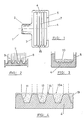
- - Figure 1 is an elevation of the open mould-drum that is envisaged by the patent.
- - Figure 2 is an enlarged detail of the formal characteristics of the section of the inner side surface of the mould.
- - Figure 3 shows a guide view, exaggerated with the object of understanding, of the position in which the plastic has been cast inside the open mould.
- - Figure 4, finally, approximately describes the final stage of the process, just before the demoulding.
- In accordance with these figures, we will firstly point out the mould-drum assembly (1), with one closed face (3) and one open face (6). From the closed front face (3) projects the shaft (2), which is connected by means of a transmission (not shown) to another driving shaft which makes the mould (1) rotate. The open face (6) is equipped with the perimetral skirt (5), of suitable height, and the inner side surface (4) of the mould is furrowed with a series of grooves (7) with suitable shape to correspond to that of the belts to be finally produced.
- It can be seen in figure 2 how the grooves (7) form recesses (9) and projections (8), which give the appropriate section for the finished belt.
- According to figure 3, the plastic (10) is poured inside the mould, so that in this first operation, the said cast material is kept in position by the perimetral skirt (5).
- Once in this position, the mould (1) is made to rotate, with which the plastic (10), due to the centrifu gal force, reaches all the side surface (4) in which the grooves (7) are contained, appropriately adjusting itself to the said surface and occupying the recesses (9) in it. After a pre-set time has passed, the assembly takes on a configuration as shown graphically in figure 4.
- In accordance with this diagram, the already set plastic material occupies the insides (11)-(12)-(13).... etc. of the grooves in the side (4) of the mould up to a height (10a), for example. Rotation of the mould is stopped at this moment and demoulding is started to obtain an assembly made up of a series of circular units which can be cut along the line indicated by the dots (14) in order to provide the desired belt.
- Obviously, the number of grooves (7) in a specific mould can be variable, as can their section, which will be adjusted to the needs and specific shape of the belt to be made.
- To make demoulding easier, passages (15) can be fitted, in which means will be arranged responsible for separating the already set belt from the mould so it can be extracted.
- In another nature of things, it might be interesting on occasions to increase the tensile strength of the belts and reduce their stretching capacity, in certain applications where thus required. To do this, the possibility of incorporating a fabric over the mould is pointed out, a fabric whose weft provides sufficient space to allow the liquid plastic to pass through so that the fabric becomes soaked and embedded in it, and so that once setting and curing have taken place, the belt has the said internal fabric reinforcement.
Claims (7)
Applications Claiming Priority (2)
| Application Number | Priority Date | Filing Date | Title |
|---|---|---|---|
| ES8801809 | 1988-06-10 | ||
| ES8801809A ES2007915A6 (en) | 1988-06-10 | 1988-06-10 | Improvements in the manufacturing of transmission belts. |
Publications (2)
| Publication Number | Publication Date |
|---|---|
| EP0349466A2 true EP0349466A2 (en) | 1990-01-03 |
| EP0349466A3 EP0349466A3 (en) | 1990-06-13 |
Family
ID=8256753
Family Applications (1)
| Application Number | Title | Priority Date | Filing Date |
|---|---|---|---|
| EP89500067A Withdrawn EP0349466A3 (en) | 1988-06-10 | 1989-06-09 | Improvements in the manufacturing of transmission belts |
Country Status (2)
| Country | Link |
|---|---|
| EP (1) | EP0349466A3 (en) |
| ES (1) | ES2007915A6 (en) |
Cited By (7)
| Publication number | Priority date | Publication date | Assignee | Title |
|---|---|---|---|---|
| WO1995000294A1 (en) * | 1993-06-17 | 1995-01-05 | Minnesota Mining And Manufacturing Company | Abrasive belts with an endless, flexible, seamless backing and methods of preparation |
| US5573619A (en) * | 1991-12-20 | 1996-11-12 | Minnesota Mining And Manufacturing Company | Method of making a coated abrasive belt with an endless, seamless backing |
| US5578096A (en) * | 1995-08-10 | 1996-11-26 | Minnesota Mining And Manufacturing Company | Method for making a spliceless coated abrasive belt and the product thereof |
| US5584897A (en) * | 1994-02-22 | 1996-12-17 | Minnesota Mining And Manufacturing Company | Method for making an endless coated abrasive article |
| US5681612A (en) * | 1993-06-17 | 1997-10-28 | Minnesota Mining And Manufacturing Company | Coated abrasives and methods of preparation |
| US6406577B1 (en) | 1991-12-20 | 2002-06-18 | 3M Innovative Properties Company | Method of making abrasive belt with an endless, seamless backing |
| US6406576B1 (en) | 1991-12-20 | 2002-06-18 | 3M Innovative Properties Company | Method of making coated abrasive belt with an endless, seamless backing |
Citations (2)
| Publication number | Priority date | Publication date | Assignee | Title |
|---|---|---|---|---|
| FR1175138A (en) * | 1957-05-15 | 1959-03-20 | Manufacturing process for endless belts, in soundproof material | |
| GB1033594A (en) * | 1962-02-15 | 1966-06-22 | Gates Rubber Co | A method of casting articles from liquid elastomers |
-
1988
- 1988-06-10 ES ES8801809A patent/ES2007915A6/en not_active Expired
-
1989
- 1989-06-09 EP EP89500067A patent/EP0349466A3/en not_active Withdrawn
Patent Citations (2)
| Publication number | Priority date | Publication date | Assignee | Title |
|---|---|---|---|---|
| FR1175138A (en) * | 1957-05-15 | 1959-03-20 | Manufacturing process for endless belts, in soundproof material | |
| GB1033594A (en) * | 1962-02-15 | 1966-06-22 | Gates Rubber Co | A method of casting articles from liquid elastomers |
Cited By (9)
| Publication number | Priority date | Publication date | Assignee | Title |
|---|---|---|---|---|
| US5573619A (en) * | 1991-12-20 | 1996-11-12 | Minnesota Mining And Manufacturing Company | Method of making a coated abrasive belt with an endless, seamless backing |
| US6066188A (en) * | 1991-12-20 | 2000-05-23 | Minnesota Mining And Manufacturing Company | Coated abrasive belt with an endless seamless backing and method of preparation |
| US6406577B1 (en) | 1991-12-20 | 2002-06-18 | 3M Innovative Properties Company | Method of making abrasive belt with an endless, seamless backing |
| US6406576B1 (en) | 1991-12-20 | 2002-06-18 | 3M Innovative Properties Company | Method of making coated abrasive belt with an endless, seamless backing |
| WO1995000294A1 (en) * | 1993-06-17 | 1995-01-05 | Minnesota Mining And Manufacturing Company | Abrasive belts with an endless, flexible, seamless backing and methods of preparation |
| US5681612A (en) * | 1993-06-17 | 1997-10-28 | Minnesota Mining And Manufacturing Company | Coated abrasives and methods of preparation |
| US5584897A (en) * | 1994-02-22 | 1996-12-17 | Minnesota Mining And Manufacturing Company | Method for making an endless coated abrasive article |
| US5578096A (en) * | 1995-08-10 | 1996-11-26 | Minnesota Mining And Manufacturing Company | Method for making a spliceless coated abrasive belt and the product thereof |
| US5830248A (en) * | 1995-08-10 | 1998-11-03 | Minnesota Mining & Manufacturing Company | Method for making a spliceless coated abrasive belt |
Also Published As
| Publication number | Publication date |
|---|---|
| EP0349466A3 (en) | 1990-06-13 |
| ES2007915A6 (en) | 1989-07-01 |
Similar Documents
| Publication | Publication Date | Title |
|---|---|---|
| US4961700A (en) | Shaping means for the production of fiber-reinforced preform articles | |
| US3028290A (en) | Method and apparatus for forming a reinforced corrugated hose | |
| EP0349466A2 (en) | Improvements in the manufacturing of transmission belts | |
| US4408980A (en) | Device for manufacturing closed hollow bodies in elastomeric material | |
| DE4037482A1 (en) | BELLOWS FROM THERMOPLASTIC ELASTOMER | |
| US4786031A (en) | Fiber reinforced thermoplastic butterfly valve element | |
| DE2231780C2 (en) | Device for producing a pneumatic tire for a motor vehicle by centrifugal casting | |
| US5733399A (en) | Method and apparatus of manufacturing synchronous drive belt with teeth which are axially interlocked with a mold surface | |
| DE1479104C3 (en) | Process for producing pneumatic tires and centrifugal casting mold for carrying out the process | |
| EP0486846A1 (en) | Method for manufacturing an air filter and apparatus to carry out such method | |
| AT398054B (en) | METHOD AND DEVICE FOR PRODUCING POWER TRANSMISSION BELTS | |
| DE2965426D1 (en) | Process of making a torus-shaped hollow body from mouldable and hardenable material | |
| JPS5934497B2 (en) | Method and apparatus for manufacturing pneumatic tires | |
| US2611151A (en) | Apparatus for making transmission belts | |
| EP0685311A2 (en) | Improved apparatus for manufacturing air filters for motor vehicles | |
| CN107415292A (en) | For the method for the drive belt for manufacturing circulation | |
| US2514964A (en) | Method and equipment for track manufacture | |
| GB1590482A (en) | Pneumatic tyre and process for its manufacture | |
| FI59551C (en) | FREQUENCY REQUIREMENT FOR FRAMING OF PNEUMATIC SHEET | |
| US3425883A (en) | Method of making a molded v-belt | |
| CN109318438A (en) | A kind of hollow tyre mould core and hollow tire and tire production method based on mold core | |
| SU1701984A1 (en) | Method of manufacturing metal-plastic rotor of rotary-blade machine | |
| GB2134439A (en) | Moulding tyres | |
| CN107303735A (en) | For the method for the drive belt for manufacturing circulation | |
| GB8620094D0 (en) | Tyre construction method |
Legal Events
| Date | Code | Title | Description |
|---|---|---|---|
| PUAI | Public reference made under article 153(3) epc to a published international application that has entered the european phase |
Free format text: ORIGINAL CODE: 0009012 |
|
| AK | Designated contracting states |
Kind code of ref document: A2 Designated state(s): DE ES FR IT |
|
| PUAL | Search report despatched |
Free format text: ORIGINAL CODE: 0009013 |
|
| AK | Designated contracting states |
Kind code of ref document: A3 Designated state(s): DE ES FR IT |
|
| 17P | Request for examination filed |
Effective date: 19901206 |
|
| 17Q | First examination report despatched |
Effective date: 19920424 |
|
| STAA | Information on the status of an ep patent application or granted ep patent |
Free format text: STATUS: THE APPLICATION IS DEEMED TO BE WITHDRAWN |
|
| 18D | Application deemed to be withdrawn |
Effective date: 19930608 |