EP0350723B1 - Valve for connecting objects to container or ducts to be sterilised in situ - Google Patents
Valve for connecting objects to container or ducts to be sterilised in situ Download PDFInfo
- Publication number
- EP0350723B1 EP0350723B1 EP89111845A EP89111845A EP0350723B1 EP 0350723 B1 EP0350723 B1 EP 0350723B1 EP 89111845 A EP89111845 A EP 89111845A EP 89111845 A EP89111845 A EP 89111845A EP 0350723 B1 EP0350723 B1 EP 0350723B1
- Authority
- EP
- European Patent Office
- Prior art keywords
- valve
- container
- opening
- interior
- sterilisable
- Prior art date
- Legal status (The legal status is an assumption and is not a legal conclusion. Google has not performed a legal analysis and makes no representation as to the accuracy of the status listed.)
- Expired - Lifetime
Links
Images


Classifications
-
- A—HUMAN NECESSITIES
- A61—MEDICAL OR VETERINARY SCIENCE; HYGIENE
- A61L—METHODS OR APPARATUS FOR STERILISING MATERIALS OR OBJECTS IN GENERAL; DISINFECTION, STERILISATION OR DEODORISATION OF AIR; CHEMICAL ASPECTS OF BANDAGES, DRESSINGS, ABSORBENT PADS OR SURGICAL ARTICLES; MATERIALS FOR BANDAGES, DRESSINGS, ABSORBENT PADS OR SURGICAL ARTICLES
- A61L2/00—Methods or apparatus for disinfecting or sterilising materials or objects other than foodstuffs or contact lenses; Accessories therefor
- A61L2/26—Accessories or devices or components used for biocidal treatment
-
- C—CHEMISTRY; METALLURGY
- C12—BIOCHEMISTRY; BEER; SPIRITS; WINE; VINEGAR; MICROBIOLOGY; ENZYMOLOGY; MUTATION OR GENETIC ENGINEERING
- C12M—APPARATUS FOR ENZYMOLOGY OR MICROBIOLOGY; APPARATUS FOR CULTURING MICROORGANISMS FOR PRODUCING BIOMASS, FOR GROWING CELLS OR FOR OBTAINING FERMENTATION OR METABOLIC PRODUCTS, i.e. BIOREACTORS OR FERMENTERS
- C12M37/00—Means for sterilizing, maintaining sterile conditions or avoiding chemical or biological contamination
Definitions
- the invention relates to a sterilizable object, such as a container or line, with a connecting valve which has an outer connection opening, a valve housing which can be sealingly attached to a connection opening of the object and which has a seat opening leading to the interior of the object, and which is guided so that it can be moved radially sealed between a blocking position and a passage position Has valve stem.
- Containers for example bioreactors, in which substances are stored and / or changed in work processes under sterile conditions, must have connection openings for sampling, for metering in various reagents and for harvesting.
- the objects to be connected must also be mounted under sterile conditions.
- a method is widespread in which a tightly clamped elastomer molding seals the sterilized container as a membrane on a special piercing nozzle of the container. This membrane is pierced by hand with a likewise sterilized pointed hollow needle, thus creating a sterile connection between the inside and the outside.
- the needle when and after removing the piercing needle from the autoclave with connected accessories such as a hose line, the needle is not contaminated with microorganisms In the non-sterile environment, this needle is wrapped with a suitable film before sterilization or wrapped in it and tightly glued.
- a sleeve with a built-in microfilter that is pushed over the needle is and is also known under the name "sterile sleeve".
- the foil or sterile sleeve must be removed by hand immediately before piercing.
- the membrane and piercing needle In order to avoid contamination of the object to be pierced, the membrane and piercing needle must be kept sterile after unpacking until they are pierced with flames. This is the riskiest phase of the known way of working.
- connection line is also kept under sterile conditions when it comes to metering in reagents, and complex line installations with corresponding valves must be provided so that the peripheral connection lines are sterilized can.
- the disadvantage is that, especially in laboratories, the steam required for this is not readily available and therefore additional investments for the corresponding infrastructure are necessary. If the connection to the container is made by means of a hollow needle by pushing it through the membrane, one has to accept the increased risk of contamination of the container contents and the environment. Piercing containers in the area below the liquid level, ie directly into the liquid, is particularly risky. The membrane is pierced at all in hazardous areas not applicable. For example, once a fermenter has been pierced, it can no longer be sterilized because the perforated membrane and the fermenter can then no longer be sterilized. It is also disadvantageous that piercing the membrane is too risky for pathogenic applications.
- EP 295 408 A2 describes a valve which leads through an outer wall of a bioreactor vessel.
- the valve enables steam sterilization of the interior of the reactor vessel and of the tubes projecting below the liquid level of the reactor vessel.
- the valve has a valve spindle provided with an axially continuous bore. It is disadvantageous that the valve does not allow the container to be hermetically sealed, since it is only suitable for optionally establishing a connection to the reactor vessel or to an immersion tube arranged in the reactor vessel.
- the valve is used with a three / two-way valve arranged below.
- a device for sterile sampling in microbiological processes which has a steam sterilization system with a condenser and a hermetically sealed sampling vessel provided with a connection valve. After sterilization in an autoclave, the sample vessel and the valve are connected to an intermediate chamber. The sample container with valve can be detached from the intermediate chamber and transported away for further treatment of the sample.
- a high pressure valve with a radially sealed displaceably guided valve spindle which can be switched between an emptying and passage position.
- the valve spindle which is axially provided with a blind bore, has two side openings opening into its peripheral surfaces. Furthermore, a valve chamber adjoining the peripheral surface of the valve spindle and an emptying chamber are arranged in the valve housing.
- the disadvantage is that the valve is only used to relieve high-pressure liquids, with both valve connecting lines being relieved against ambient pressure in the emptying position.
- a sterilizable object such as a container or line, with a connecting valve
- a connecting valve which has an outer connection opening
- a valve housing which can be sealingly attached to a connection opening of the object and leads to the interior of the object Seat opening, which has a radially sealingly displaceable valve spindle between a blocking position and a passage position. Seals Valve disc with radial seal in the closed position from the drain or feed opening.
- the object of the invention is to provide another valve design that has a particularly small dead corner for applications in biotechnology, so that the risk of contamination is reduced.
- valve designs can serve simultaneously as a shut-off valve and as a changeover valve for connection to an immersion tube. They can therefore be used particularly universally for the needs of biotechnology. This universal application means that the number of valves on bioreactors can be reduced, which not only achieves cost advantages, but also reduces the risk of contamination of valuable batches.
- valves It is possible to first mount the valve under non-sterile conditions.
- the object to be connected is sterilized, i.e. only after the special connection valves have been firmly and tightly mounted on them in the closed state.
- the still non-sterile valve sections are sterilized with the object itself. It is irrelevant whether the connected valves are below or above the liquid level.
- the connection valves are only opened and put into operation after the connected objects have been sterilized on site. This means that these valves can also be used in potentially explosive areas.
- valves can be differentiated in terms of their opening direction. There are also significant differences as to whether a valve chamber is provided or not.
- the connection opening can either be guided by a plunger or can be connected directly to a valve chamber.
- connection valve has a connection to an immersion tube. It is thus possible for the end of the valve spindle facing away from the container interior to be arranged so as to be movable within an immersion tube and to be sealed off from it at least in the passage position. As a result, the valve can also be connected to immersion pipes in a particularly inexpensive manner without great design effort.
- the seal ensures that the valves do not have to be arranged below the liquid level for removal purposes, since the seal also seals against negative pressure.
- the valve housing it is possible for the valve housing to be designed as a tubular extension projecting into the container with lateral openings, which at the end has a coupling for mounting an immersion tube.
- valve stem is sealed at least two points from the valve housing, so that the seals form a space around the stem, in which one or more holes are arranged opening.
- security can advantageously be increased by passing a sterilizing medium through the barrier space even during the process and / or superimposing it with pressure.
- connection valve has a connection to a check valve opening in the direction of the container.
- a check valve is realized in an advantageously simple and inexpensive manner.
- a leak occurs in the pressure area of the dosing line, as can happen, for example, when the hose of a hose pump is worn through. The supply pressure then falls. Since the container is usually operated with excess pressure, this leads to a backlash of process liquid or process exhaust gas, depending on the location of the valve. The associated consequences are advantageously avoided by the check valve.
- valve housing is arranged within an installation part, which is preferably tubular and has an outer collar at one end and an external thread for a union nut or screw at the other end, serves for easier assembly.
- installation part has an opening with an internal thread with a collar, into which the screw with the valve is screwed.
- a collar formed on the valve is tensioned by the screw against the collar of the opening.
- valve spindle, the valve housing and the installation part are arranged to form the valve chamber.
- the seal between the valve spindle and the valve housing on the side facing away from the container interior is a membrane seal.
- This type of seal has the advantage that the sealing points are immobile. In other words, there are no seals against the non-sterile environment that slide on sealing surfaces. Leakage losses can thereby be reduced. This is particularly advantageous if the valve is actuated several times during a work process. This applies in particular if the membrane seal is a bellows or an elastic hose.
- connection valve according to the invention is designated by 1 and by 2 a sterilizable container.
- the sterilizable container 2 has openings 3 in its container wall 4.
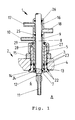
- the valve 1 has a valve housing 5 which, in the installed position to the interior 6 of the container, opens into a seat opening 7, in which the valve spindle 8 is arranged to be axially displaceable.
- the valve chamber 9, into which an outer connection opening 10 opens, is formed by valve housing 5 and valve spindle 8.
- the valve tappet 8 has a through bore 11 in its lower part, which connects two lateral openings 12 and the opening in the end face of the valve spindle 8.
- an installation part 13 is arranged between the container 2 and valve 1, which is inserted from the container interior 6 into the connection opening 3 up to the stop 14.
- the mounting part 13 is clamped to the container wall 4 by means of nut 15, which is screwed onto a thread of the mounting part 13
- valve chamber 9 there is also a blocking chamber 16 arranged in an annular manner around the valve tappet 8 with an inlet opening 17 and an outlet opening 18.
- the seals 22 seal the container and the valve housing against the interior of the container.
- the seals 23 serve to seal the flushing opening or the opening and the bore in the container wall.
- the seal 24 seals the valve chamber 9 from the container interior 6; while the seal 25 seals the valve chamber 9 to the outside.
- the seal 26 is provided so that the sealing chamber is sealed both to the outside and to the valve chamber 9 by the seals 26 and 25.
- the valve is inserted into a cylindrical bore of the mounting part 13 and clamped to it by means of the union nut 27, which has the same thread as the nut 15.
- the union nut 27 is rotatably held between the collar 28 of the valve housing and the locking ring 29.
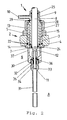
- Fig. 2 shows the connection valve according to the invention as a section with an additional bracket 30 on the mounting part 13 for fastening an immersion tube 31.
- the mounting part 13 is extended to the interior of the container 6 and provided with a thread 32 at its end, into the insertion end 33 of the immersion tube 31 can be screwed in.
- the valve spindle 8 has a section 34 with a larger and section 35 with a smaller diameter at its end facing the container interior 6.
- both sections of the valve tappet end are inside the dip tube 31.
- section 35 of the valve tappet end is outside the dip tube, the seal 36 then between section 34 and the dip tube is arranged.
- the immersion tube holder has openings 37 so that the space between the holder and valve tappet in the blocking position A can be reached by sterilizing media.
- Fig. 3 shows a different kind of design of the dip tube attachment.
- the dip tube 31 is inserted into the passage opening 11 of the valve lifter 8.
- the valve tappet 8 has a thread 38 for the union nut at its end facing the interior 6 of the container 39 on.
- a pinch seal 40 is inserted between the end of the valve lifter and the union nut 39. By tightening the union nut 39, the seal 40 is compressed between the end of the valve tappet and the union nut 39, so that it is supported on the dip tube 31 and thereby firmly connects the dip tube to the valve tappet 8.
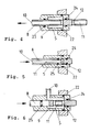
- Fig. 4 shows a section through the valve according to the invention as an inline version. This design differs from the corner valve-like designs described above in that the connection is made coaxially with the valve spindle 8 via the connection opening 10.
- the valve spindle 8 has a coaxial guided bore which opens into two lateral outlet openings within the valve chamber 9. The arrow indicates the direction in which the valve stem is moved to open.
- FIG. 5 shows a section through a further inline version which, in contrast to the previously described embodiments, is designed without a valve chamber. This results in an advantageously small valve volume, which can be sterilized more easily.
- the valve spindle has only a single through-bore 11, which opens into two lateral openings 12. In the locked position, the openings 12 are closed by the valve housing 5.
- the rings 24 and 25 which seal the openings 12 laterally are not arranged inside the valve housing, as in the cases described above, but on the valve spindle. To open the valve, the valve spindle is moved in the direction of the arrow towards the inside of the container. This embodiment leaves produce themselves with an advantageously low technical manufacturing effort.
- Figure 6 shows a section through another embodiment of the valve according to the invention, which is designed as a corner valve, but as in Figure 6 is moved to open in the direction of the arrow towards the interior of the container in the direction of the arrow.
- the valve spindle 8 has a through hole 11 in a partial area, which opens on both sides in lateral openings 12 within the valve chamber 9.
- the valve chamber is sealed off from the container by a ring 24 arranged inside the housing.
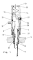
- Figure 7 shows a valve design that opens automatically as soon as a medium is supplied under pressure.
- the valve is drawn in the through position to the left of the dash-dotted line and to the right of the line in the blocking position.
- the valve housing 5 is fastened by means of a union nut 27 on an externally threaded connecting piece 51 of the container.
- the valve tappet 8 in this embodiment which is designed as a corner valve, is shaped as a piston 58 at its end facing away from the container. On the outer surface of the piston 58 there is a locking groove 55 into which the ball 56 engages in the locking position by means of the spring 57.
- a spring 54 is arranged, which presses the piston 58 with valve tappet 8 automatically into the blocking position shown on the right of the dash-dotted line as soon as no pressure is present in the valve chamber. So that the piston 58 at his Hub builds up no back pressure within the valve housing, the valve housing 5 is vented through the opening 53.
- the valve is actuated by supplying a medium under pressure through the connection opening 10. Due to the larger area of the piston-like end 58 of the valve spindle 8, the valve spindle is moved from the position shown on the right by the dash-dotted line to the position shown on the left of the line. It presses the ball 56 against the force of the spring 57 out of the locking groove 55. As soon as the through-bore 11 communicates with the valve chamber, the pressure built up in the valve chamber decreases to such an extent that the piston 58 comes to a standstill in the equilibrium position.
- valve 8 shows a valve variant in which, unlike the variants described above, the valve chamber 9 is formed on the outside by the mounting part 13, on the top by the end face of the valve housing 5 and below by a collar on the valve tappet 8.
- the through position of the valve is shown to the left of the dash-dotted center line, while the valve is shown in the blocking position to the right of the dash-dotted center line. All seals are designed as external O-rings, so that the valve can be produced particularly inexpensively even for small diameters.
- valves according to the invention function as follows: In the position A shown in FIG. 1, the valve hermetically seals off the container interior 6 from the outside. In this position, the container interior is sterilized on site. The through hole 11 and the lateral openings 12 are located inside the container. By actuating the valve spindle 8 out of the container interior, the lateral bores 12 are moved until they are located within the valve chamber 9. The valve chamber 9 then communicates with the container interior 6 via the lateral openings 12 and the through bore 11. In this position, a substance can be metered into a batch in the container via the connection opening 10, or, depending on the installation location of the valve, substances from the Container interior are deducted. For special applications, a blocking chamber 16 can also be provided, through which a sterilizing medium, preferably under pressure, is continuously passed or introduced through the openings 17, 18. Contamination of the outside world can be safely prevented.
- the holder 30 for the immersion tube can either be firmly connected to the container or, as shown, to the installation part or else to the valve housing. In all cases, the dip tube remains stationary relative to the container.
- a solution can also be chosen, as shown in FIG. 3, in which the immersion tube 31 is fixedly connected to the valve tappet and thus moves with the valve tappet relative to the container.
- the movement can also be force-actuated by cylinders or electric linear drives which are connected to the valve spindle 8.
- this sliding seal can also be replaced by a membrane seal which is firmly held in the valve housing 5 on one side and is connected to the valve stem 8 on the other side.
- a membrane seal which is firmly held in the valve housing 5 on one side and is connected to the valve stem 8 on the other side.
- such a seal can be designed to be elastic, either as a bellows or as a hose.
Abstract
Description
Die Erfindung betrifft ein sterilisierbares Objekt, wie Behälter oder Leitung, mit Anschlußventil, das eine äußere Anschlußöffnung, ein an einer Anschlußöffnung des Objekts dichtend anbringbares Ventilgehäuse mit zum Innenraum des Objekts führender Sitzöffnung, eine in dieser zwischen einer Sperrstellung und einer Durchtrittsstellung radial abgedichtet verschiebbar geführte Ventilspindel aufweist.The invention relates to a sterilizable object, such as a container or line, with a connecting valve which has an outer connection opening, a valve housing which can be sealingly attached to a connection opening of the object and which has a seat opening leading to the interior of the object, and which is guided so that it can be moved radially sealed between a blocking position and a passage position Has valve stem.
Behälter, z.B. Bioreaktoren, in denen unter sterilen Bedingungen Stoffe gelagert und/oder in Arbeitsprozessen verändert werden, müssen zur Probenahme, zum Hinzu-dosieren verschiedener Reagenzien sowie zum Abernten Anschlußöffnungen aufweisen. Die anzuschließenden Objekte müssen dabei ebenfalls unter sterilen Bedingungen montiert werden. Weit verbreitet ist ein Verfahren, bei dem auf einem speziellen Anstechstutzen des Behälters ein dicht eingespannter Elastomerformling als Membran den sterilisierten Behälter verschließt. Mit einer ebenfalls sterilisierten spitzen Hohlnadel wird diese Membran von Hand durchstochen und so eine Sterilverbindung zwischen Innen und Außen herstellt. Damit bei und nach dem Entnehmen der Anstechnadel aus dem Autoklaven mit angeschlossenem Zubehör wie z.B. Schlauchleitung keine Kontamination der Nadel mit Mikroorganismen aus der unsterilen Umgebung stattfinden kann, wird diese Nadel vor dem Sterilisieren mit einer geeigneten Folie umwickelt bzw. in diese eingepackt und dicht verklebt. Den gleichen Zweck erreicht man durch eine Hülse mit eingebautem Mikrofilter, die über die Nadel geschoben wird und auch unter dem Namen "Sterilhülse" bekannt ist. Folie bzw. Sterilhülse müssen unmittelbar vor dem Anstechen von Hand entfernt werden. Um eine Kontamination des anzustechenden Objektes zu vermeiden, müssen Membran und Anstechnadel nach dem Auspacken bis zum Anstechen mit Flammen steril gehalten werden. Dies ist die risikoreichste Phase der bekannten Arbeitsweise.Containers, for example bioreactors, in which substances are stored and / or changed in work processes under sterile conditions, must have connection openings for sampling, for metering in various reagents and for harvesting. The objects to be connected must also be mounted under sterile conditions. A method is widespread in which a tightly clamped elastomer molding seals the sterilized container as a membrane on a special piercing nozzle of the container. This membrane is pierced by hand with a likewise sterilized pointed hollow needle, thus creating a sterile connection between the inside and the outside. This means that when and after removing the piercing needle from the autoclave with connected accessories such as a hose line, the needle is not contaminated with microorganisms In the non-sterile environment, this needle is wrapped with a suitable film before sterilization or wrapped in it and tightly glued. The same purpose is achieved by a sleeve with a built-in microfilter that is pushed over the needle is and is also known under the name "sterile sleeve". The foil or sterile sleeve must be removed by hand immediately before piercing. In order to avoid contamination of the object to be pierced, the membrane and piercing needle must be kept sterile after unpacking until they are pierced with flames. This is the riskiest phase of the known way of working.
Zur Verringerung dieses Risikos werden, wenn es um das Hinzudosieren von Reagenzien geht, Dosierventile eingesetzt bzw. die erforderlichen Anschlußleitungen fest installiert und zusätzlich auch die Anschlußleitung unter sterilen Bedingungen gehalten, wobei aufwendige Leitungsinstallationen mit entsprechenden Ventilen vorgesehen werden müssen, damit die peripheren Anschlußleitungen sterilisiert werden können. Dazu gehören meist Dampf- und Kondensatanschlüsse und aufwendige Steuerungseinrichtungen, damit diese Ventile dann in genau festgelegten Sequenzen bedient bzw. angesteuert werden. Nur auf diese Weise ist die geforderte Sicherheit zu gewährleisten.To reduce this risk, metering valves are used or the necessary connection lines are permanently installed and the connection line is also kept under sterile conditions when it comes to metering in reagents, and complex line installations with corresponding valves must be provided so that the peripheral connection lines are sterilized can. This usually includes steam and condensate connections and complex control devices so that these valves can then be operated or controlled in precisely defined sequences. This is the only way to ensure the required security.
Nachteilig ist, daß besonders in Labors, der dazu notwendige Dampf nicht ohne weiteres zur Verfügung steht und deshalb zusätzliche Investitionen für die entsprechende Infrastruktur notwendig werden. Wird die Verbindung zum Behälter mittels einer Hohlnadel hergestellt, indem diese durch die Membran hindurchgestoßen wird, so muß man dabei das erhöhte Risiko einer Kontamination des Behälterinhaltes und der Umgebung in Kauf nehmen. Besonders risikoreich ist dabei ein Anstechen von Behältern im Bereich unterhalb des Flüssigkeitsspiegels, also direkt in die Flüssigkeit. In explosionsgefährdeten Bereichen ist das Durchstechen der Membran überhaupt nicht anwendbar. Wenn beispielsweise ein Fermenter einmal angestochen wurde, kann dieser nicht mehr nachsterilisiert werden, da die perforierte Membran und der Fermenter dann nicht mehr sterilisiert werden können. Außerdem ist nachteilig, daR für pathogene Anwendungen, ein Durchstechen der Membran zu risikoreich ist.The disadvantage is that, especially in laboratories, the steam required for this is not readily available and therefore additional investments for the corresponding infrastructure are necessary. If the connection to the container is made by means of a hollow needle by pushing it through the membrane, one has to accept the increased risk of contamination of the container contents and the environment. Piercing containers in the area below the liquid level, ie directly into the liquid, is particularly risky. The membrane is pierced at all in hazardous areas not applicable. For example, once a fermenter has been pierced, it can no longer be sterilized because the perforated membrane and the fermenter can then no longer be sterilized. It is also disadvantageous that piercing the membrane is too risky for pathogenic applications.
Die nachteiligen Folgen einer Kontamination, die bei den bekannten Verfahren nicht auszuschließen sind, sind in der Regel schwerwiegend und liegen beispielsweise darin begründet, daß Mensch, Tier und Pflanze in der Umgebung gefährdet werden. Außerdem führt die Kontamination von Prozeßchargen zu höheren Kosten durch die verlorene Charge und deren umweltgerechter Beseitigung. Die Produktionsziele werden dann nicht erreicht. Es müssen zusätzliche Anlagen als Reserve bereitgestellt werden. Dies hat natürlich wiederum erhöhte Investitionskosten zur Folge.The disadvantageous consequences of contamination, which cannot be ruled out in the known methods, are generally serious and are due, for example, to the fact that humans, animals and plants in the environment are endangered. In addition, the contamination of process batches leads to higher costs due to the lost batch and its environmentally friendly disposal. The production goals will then not be achieved. Additional facilities must be made available as a reserve. Of course, this in turn results in increased investment costs.
In der EP 295 408 A2 wird ein Ventil beschrieben, das durch eine Außenwand eines Bioreaktorgefäßes hindurchführt. Mit dem Ventil wird eine Dampfsterilisation des Innenraumes des Reaktorgefäßes und der unter dem Flüssigkeitsspiegel des Reaktorgefäßes ragenden Rohre ermöglicht. Das Ventil weist eine mit einer axial durchgehenden Bohrung versehene Ventilspindel auf. Nachteilig ist, daß das Ventil ein hermetisches Verschließen des Behälters nicht ermöglicht, da es lediglich dazu geeignet ist, wahlweise eine Verbindung zum Reaktorgefäß oder zu einem im Reaktorgefäß angeordneten Tauchrohr herzustellen. Das Ventil wird mit einem nachfolgend angeordneten Drei/Zwei-Wegeventil verwendet.EP 295 408 A2 describes a valve which leads through an outer wall of a bioreactor vessel. The valve enables steam sterilization of the interior of the reactor vessel and of the tubes projecting below the liquid level of the reactor vessel. The valve has a valve spindle provided with an axially continuous bore. It is disadvantageous that the valve does not allow the container to be hermetically sealed, since it is only suitable for optionally establishing a connection to the reactor vessel or to an immersion tube arranged in the reactor vessel. The valve is used with a three / two-way valve arranged below.
Aus der SU 597 938 ist eine Vorrichtung zur sterilen Probennahme bei mikrobiologischen Verfahren bekannt, die ein Dampfsterilisationssystem mit Kondensator und hermetisch abgedichtetes mit einem Anschlußventil versehenes Probennahmegefäß aufweist. Nach der Sterilisation in einem Autoklaven werden das Probengefäß und das Ventil mit einer Zwischenkammer verbunden. Das Probengefäß mit Ventil kann an der Zwischenkammer gelöst werden und zur Weiterbehandlung der Probe abtransportiert werden.From SU 597 938 a device for sterile sampling in microbiological processes is known, which has a steam sterilization system with a condenser and a hermetically sealed sampling vessel provided with a connection valve. After sterilization in an autoclave, the sample vessel and the valve are connected to an intermediate chamber. The sample container with valve can be detached from the intermediate chamber and transported away for further treatment of the sample.
Aus der US 4,665,944 ist ein Hochdruckventil mit einer radial abgedichteten verschiebbar geführten Ventilspindel bekannt, das zwischen einer Entleerungs- und Durchtrittsstellung schaltbar ist. Die axial mit einer Sackbohrung versehene Ventilspindel weist zwei deren Umfangsflächen mündende Seitenöffnungen auf. Ferner sind im Ventilgehäuse eine an die Umfangsfläche der Ventilspindel angrenzende Ventilkammer und eine Entleerungskammer angeordnet. Nachteilig ist, daß das Ventil lediglich zur Entspannung unter Hochdruck stehender Flüssigkeiten dient, wobei beide Ventilanschlußleitungen in der Entleerungsstellung gegen Umgebungsdruck entspannt werden.From US 4,665,944 a high pressure valve with a radially sealed displaceably guided valve spindle is known, which can be switched between an emptying and passage position. The valve spindle, which is axially provided with a blind bore, has two side openings opening into its peripheral surfaces. Furthermore, a valve chamber adjoining the peripheral surface of the valve spindle and an emptying chamber are arranged in the valve housing. The disadvantage is that the valve is only used to relieve high-pressure liquids, with both valve connecting lines being relieved against ambient pressure in the emptying position.
Aus der DE-A-2.609.825, von der die Erfindung ausgeht, ist ein sterilisierbares Objekt, wie Behälter oder Leitung, mit Anschlußventil bekannt, das eine äußere Anschlußöffnung, ein an einer Anschlußöffnung des Objekts dichtend anbringbares Ventilgehäuse mit zum Innenraum des Objekts führender Sitzöffnung, eine in dieser zwischen einer Sperrstellung und einer Durchtrittsstellung radial abdichtend verschiebbar geführte Ventilspindel aufweist. Dabei dichtet ein Ventilteller mit radialer Dichtung in der Schließstellung die Ablauf- bzw. Zufuhröffnung ab.From DE-A-2.609.825, from which the invention is based, a sterilizable object, such as a container or line, with a connecting valve is known, which has an outer connection opening, a valve housing which can be sealingly attached to a connection opening of the object and leads to the interior of the object Seat opening, which has a radially sealingly displaceable valve spindle between a blocking position and a passage position. Seals Valve disc with radial seal in the closed position from the drain or feed opening.
Sie ist ungeeignet, eine Verbindung zu einem Tauchrohr herzustellen.It is unsuitable for connecting to a dip tube.
Aufgabe der Erfindung ist es, eine andere Ventilbauform anzugeben, die für Anwendungsfälle in der Biotechnologie über besonders wenige tote Ecke verfügt, damit das Kontaminationsrisiko vermindert wird.The object of the invention is to provide another valve design that has a particularly small dead corner for applications in biotechnology, so that the risk of contamination is reduced.
Diese Aufgabe wird durch jede der Merkmalskombinationen der nebengeordneten Ansprüche 1 bis 3 gelöst.This object is achieved by each of the combinations of features of the
Durch einfache Zusatzausrüstungen können diese Ventilbauformen gleichzeitig als Abschlußventil und als Umschaltventil zur Verbindung mit einem Tauchrohr dienen. Sie sind damit besonders universell für die belange der Biotechnologie einsetzbar. Durch diese universelle Einsetzbarkeit kann die Anzahl der Ventile an Bioreaktoren vermindert werden, wodurch nicht nur Kostenvorteile erzielt werden, sondern auch das Kontaminationsrisiko wertvoller Chargen vermindert wird.With simple additional equipment, these valve designs can serve simultaneously as a shut-off valve and as a changeover valve for connection to an immersion tube. They can therefore be used particularly universally for the needs of biotechnology. This universal application means that the number of valves on bioreactors can be reduced, which not only achieves cost advantages, but also reduces the risk of contamination of valuable batches.
Vorteilhaft können somit auch bestehende Anlagen nachgerüstet werden, ohne daß aufwendige Leitungsführungen und Steuereinrichtungen für ein zusätzliches Sterilisationsmedium vorzusehen wären.Existing systems can thus advantageously also be retrofitted without having to provide complex cable routing and control devices for an additional sterilization medium.
Es ist möglich, das Ventil zunächst unter unsterilen Bedingungen zu montieren. Im geschlossenen Zustand des Ventils wird das anzuschließende Objekt sterilisiert, d.h. erst, nachdem die speziellen Anschlußventile in geschlossenem Zustand an diesem fest und dicht montiert worden sind. Dadurch werden die noch unsterilen wesentlichen Ventilpartien mit dem Objekt selbst sterilisiert. Es ist unerheblich, ob die angeschlossenen Ventile unter oder über dem Flüssigkeitsspiegel liegen. Erst nach der vor Ort erfolgten Sterilisation der angeschlossenen Objekte werden die Anschlußventile geöffnet und in Betrieb genommen. Dadurch ist der Einsatz dieser Ventile auch in explosionsgefährdeten Bereichen möglich.It is possible to first mount the valve under non-sterile conditions. When the valve is closed, the object to be connected is sterilized, i.e. only after the special connection valves have been firmly and tightly mounted on them in the closed state. As a result, the still non-sterile valve sections are sterilized with the object itself. It is irrelevant whether the connected valves are below or above the liquid level. The connection valves are only opened and put into operation after the connected objects have been sterilized on site. This means that these valves can also be used in potentially explosive areas.
Die Ventile lassen sich hinsichtlich ihrer Öffnungsrichtung unterscheiden. Außerdem bestehen wesentliche Unterschiede darin, ob eine Ventilkammer vorgesehen ist oder nicht. Die Anschlußöffnung kann entweder durch einen Stößel geführt sein oder aber direkt mit einer Ventilkammer verbunden sein.The valves can be differentiated in terms of their opening direction. There are also significant differences as to whether a valve chamber is provided or not. The connection opening can either be guided by a plunger or can be connected directly to a valve chamber.
In weiterer Ausgestaltung der Erfindung ist vorgesehen, daß das Anschlußventil eine Verbindung zu einem Tauchrohr aufweist. Damit ist es möglich, daß das von dem Behälterinnenraum abgewandte Ende der Ventilspindel innerhalb eines Tauchrohres beweglich angeordnet ist und gegenüber diesem mindestens in Durchtrittsstellung abgedichtet ist. Dadurch läßt sich das Ventil auch besonders günstig ohne großen konstruktiven Aufwand an Tauchrohre anschließen. Die Abdichtung sorgt dafür, daß die Ventile zu Entnahmezwecken nicht unterhalb des Flüssigkeitsspiegels angeordnet werden müssen, da die Dichtung auch gegen Unterdruck abdichtet. Alternativ ist es möglich, daß das Ventilgehäuse als ein in den Behälter ragender rohrförmiger Fortsatz mit seitlichen Öffnungen ausgebildet ist, der am Ende eine Kupplung zur Montage eines Tauchrohres aufweist. Dies ermöglicht eine besonders einfache Befestigung des Tauchrohres direkt am Ventil selbst. Zusätzliche Befestigungsorgane innerhalb des Behälters entfallen dadurch vorteilhaft. Durch die zusätzlichen Bohrungen innerhalb des Ventilgehäuses wird auch eine einwandfreie Sterilisation von schwer zugänglichen Stellen des Ventils bis zum Ventilsitz beim Sterilisieren des Behälters vor Ort erreicht. Ebenso ist es möglich, daß das Tauchrohr oder die Tauchleitung mit der Ventilspindel verbunden ist, wobei die Verbindung vorzugsweise mittels Überwurfmutter und Quetschdichtung erfolgt. Diese Befestigungsweise ermöglicht besonders kostengünstige Tauchrohrkonstruktionen, da Befestigungselemente innerhalb des sterilen Behälters vorteilhaft entfallen können.In a further embodiment of the invention it is provided that the connection valve has a connection to an immersion tube. It is thus possible for the end of the valve spindle facing away from the container interior to be arranged so as to be movable within an immersion tube and to be sealed off from it at least in the passage position. As a result, the valve can also be connected to immersion pipes in a particularly inexpensive manner without great design effort. The seal ensures that the valves do not have to be arranged below the liquid level for removal purposes, since the seal also seals against negative pressure. Alternatively, it is possible for the valve housing to be designed as a tubular extension projecting into the container with lateral openings, which at the end has a coupling for mounting an immersion tube. This enables a particularly simple attachment of the dip tube directly to the valve itself. This advantageously eliminates the need for additional attachment members within the container. The additional holes in the valve housing also ensure perfect sterilization from difficult to access areas of the valve to the valve seat when the container is sterilized on site. It is also possible for the immersion tube or the immersion line to be connected to the valve spindle, the connection preferably being made by means of a union nut and pinch seal. This type of attachment enables particularly inexpensive immersion tube designs, since attachment elements within the sterile container can advantageously be omitted.
In weiterer Ausgestaltung der Erfindung ist vorgesehen, daß das vom Behälterinnenraum abgewandte Ende der Ventilspindel an mindestens zwei Stellen gegenüber dem Ventilgehäuse abgedichtet ist, so daß die Dichtungen einen Sperraum um die Spindel bilden, in den ein oder mehrere Bohrungen mündend angeordnet sind. Für besonders hohe Anforderungen bei risikoreichen Prozessen läßt sich die Sicherheit vorteilhaft dadurch erhöhen, indem durch den Sperraum auch während des Prozesses ein sterilisierendes Medium hindurchgeleitet wird und/oder mit Druck überlagert wird.In a further embodiment of the invention it is provided that the end facing away from the container interior Valve stem is sealed at least two points from the valve housing, so that the seals form a space around the stem, in which one or more holes are arranged opening. For particularly high requirements in high-risk processes, security can advantageously be increased by passing a sterilizing medium through the barrier space even during the process and / or superimposing it with pressure.
In weiterer Ausgestaltung der Erfindung ist vorgesehen, daß das Anschlußventil eine Verbindung zu einem in Richtung des Behälters öffnenden Rückschlagventil aufweist. Besonders wenig tote Ecken, die eine sichere Sterilisation gefährden könnten, ergeben sich wenn die Ventilspindel und oder das Tauchrohr am zum Behälterinnenraum gerichteten Ende nur seitliche Öffnungen der Durchgangsbohrung aufweisen, die vorzugsweise von einer elastischen Membran, insbesondere von einem elastischen Schlauch, verschlossen sind. Dadurch wird auf vorteilhaft einfache und kostengünstige Weise ein Rückschlagventil verwirklicht. Beim Zudosieren von Medien in den Behälter kann es erfahrungsgemäß vorkommen, daß ein Leck im Druckbereich der Zudosierleitung entsteht, wie es beispielsweise beim Durchscheuern des Schlauches einer Schlauchpumpe geschehen kann. Der Zufuhrdruck fällt dann zusammen. Da üblicherweise der Behälter mit Überdruck betrieben wird, führt dies zu einem Zurückschlagen von Prozeßflüssigkeit oder Prozeßabgas, je nachdem, an welchem Ort das Ventil angeordnet ist. Die damit verbundenen Folgen werden vorteilhaft durch das Rückschlagventil vermieden.In a further embodiment of the invention it is provided that the connection valve has a connection to a check valve opening in the direction of the container. There are particularly few dead corners that could jeopardize safe sterilization if the valve spindle and or the immersion tube only have lateral openings in the through hole at the end facing the container interior, which are preferably closed by an elastic membrane, in particular by an elastic hose. As a result, a check valve is realized in an advantageously simple and inexpensive manner. Experience has shown that when media are dosed into the container, a leak occurs in the pressure area of the dosing line, as can happen, for example, when the hose of a hose pump is worn through. The supply pressure then falls. Since the container is usually operated with excess pressure, this leads to a backlash of process liquid or process exhaust gas, depending on the location of the valve. The associated consequences are advantageously avoided by the check valve.
Auch die Maßnahme, daß das Ventilgehäuse innerhalb eines Einbauteils angeordnet ist, das vorzugsweise rohrförmig ausgebildet ist und an einem Ende einen äußeren Bund, und am anderen Ende ein Außengewinde für eine Überwurfmutter oder -schraube aufweist, dient einer einfacheren Montage. Im Falle einer Überwurfschraube weist das Einbauteil eine Öffnung mit einem Innengewinde mit Bund auf, in das die Schraube mit dem Ventil eingeschraubt wird. Dabei wird ein am Ventil angeformter Bund von der Schraube gegen den Bund der Öffnung gespannt.The measure that the valve housing is arranged within an installation part, which is preferably tubular and has an outer collar at one end and an external thread for a union nut or screw at the other end, serves for easier assembly. In the case of a union screw, the installation part has an opening with an internal thread with a collar, into which the screw with the valve is screwed. A collar formed on the valve is tensioned by the screw against the collar of the opening.
In weiterer Ausgestaltung der Erfindung ist vorgesehen, daß die Ventilspindel, das Ventilgehäuse und das Einbauteil die Ventilkammer bildend angeordnet sind. Dadurch wird eine fertigungstechnisch besonders günstige Bauweise erzielt.In a further embodiment of the invention it is provided that the valve spindle, the valve housing and the installation part are arranged to form the valve chamber. As a result, a construction method that is particularly favorable in terms of production technology is achieved.
In weiterer Ausgestaltung der Erfindung ist vorgesehen, daß die Dichtung zwischen Ventilspindel und Ventilgehäuse auf der dem Behälterinnenraum abgewandten Seite eine Membrandichtung ist. Diese Dichtungsart weist den Vorteil auf, daß die Dichtstellen ortsunveränderlich sind. Anders ausgedrückt: es gibt gegen die unsterile Umgebung keine Dichtungen, die auf Dichtflächen gleiten. Dadurch können Leckverluste verringert werden. Dies ist besonders vorteilhaft, wenn während eines Arbeitsprozesses das Ventil mehrmalig betätigt wird. Dies gilt insbesondere, wenn die Membrandichtung ein Faltenbalg oder ein elastischer Schlauch ist.In a further embodiment of the invention it is provided that the seal between the valve spindle and the valve housing on the side facing away from the container interior is a membrane seal. This type of seal has the advantage that the sealing points are immobile. In other words, there are no seals against the non-sterile environment that slide on sealing surfaces. Leakage losses can thereby be reduced. This is particularly advantageous if the valve is actuated several times during a work process. This applies in particular if the membrane seal is a bellows or an elastic hose.
Die Erfindung wird nachstehend in Form bevorzugter Ausführungsbeispiele unter Bezugnahme auf beiliegende Zeichnungen beschrieben, wobei gleichartige Teile in den verschiedenen Zeichnungsfiguren mit denselben Bezugszeichen versehen sind.The invention is described below in the form of preferred exemplary embodiments with reference to the accompanying drawings, similar parts in FIG the different drawing figures are provided with the same reference numerals.
Die Figuren zeigen:
- Fig. 1
- einen Schnitt durch das erfindungsgemäße Anschlußventil mit doppelter Abdichtung der Ventilspindel,
- Fig. 2
- einen Schnitt durch das erfindungsgemäße Ventil mit einem relativ zum Behälter feststehenden Tauchrohr, das am Behälterstutzen (und nicht am Ventil) montiert ist,
- Fig. 3
- einen Schnitt durch das erfindungsgemäße Ventil mit einem relativ zum Behälter beweglichen Tauchrohr,
- Fig. 4
- einen Schnitt durch das erfindungsgemäße Ventil in Sperrstellung als Inline-Ausführung
- Fig. 5
- einen Schnitt durch das erfindungsgemäße Ventil in Sperrstellung als Inline-Ausführung, jedoch ohne Ventilkammer,
- Fig. 6
- einen Schnitt durch das erfindungsgemäße Ventil in Sperrstellung als Eckventil mit entgegengesetzter Betätigungsrichtung,
- Fig. 7
- einen Schnitt durch ein selbsttätig öffendes Ventil gemäß der Erfindung und
- Fig. 8
- einen Schnitt durch eine Ventilvariate mit Ventilkammer.
- Fig. 1
- 2 shows a section through the connection valve according to the invention with double sealing of the valve spindle,
- Fig. 2
- 2 shows a section through the valve according to the invention with a dip tube which is fixed relative to the container and is mounted on the container neck (and not on the valve),
- Fig. 3
- 2 shows a section through the valve according to the invention with an immersion tube that is movable relative to the container,
- Fig. 4
- a section through the valve according to the invention in the blocking position as an inline version
- Fig. 5
- 2 shows a section through the valve according to the invention in the blocking position as an inline version, but without a valve chamber,
- Fig. 6
- 4 shows a section through the valve according to the invention in the blocking position as a corner valve with the opposite actuation direction,
- Fig. 7
- a section through an automatically opening valve according to the invention and
- Fig. 8
- a section through a valve variant with valve chamber.
In Fig. 1 ist mit 1 das erfindungsgemäße Anschlußventilbezeichnet und mit 2 ein sterilisierbarer Behälter. Der sterilisierbare Behälter 2 weist Öffnungen 3 in seiner Behälterwandung 4 auf.In Fig. 1 the connection valve according to the invention is designated by 1 and by 2 a sterilizable container. The
Das Ventil 1 hat ein Ventilgehäuse 5, das in der Einbaustellung zum Innenraum 6 des Behälters in eine Sitzöffnung 7 mündet, in der die Ventilspindel 8 axial verschieblich angeordnet ist. Von Ventilgehäuse 5 und Ventilspindel 8 wird die Ventilkammer 9 gebildet, in die eine äußere Anschlußöffnung 10 mündet. Der Ventilstößel 8 weist in seinem unteren Teil eine Durchgangsbohrung 11 auf, die zwei seitliche Öffnungen 12 und die Öffnung in der Stirnfläche der Ventilspindel 8 verbindet.The
Zur Montage des Ventils ist zwischen Behälter 2 und Ventil 1 ein Einbauteil 13 angeordnet, das vom Behälterinnenraum 6 in die Anschlußöffnung 3 bis zum Anschlag 14 eingesteckt ist. Mittels Mutter 15, die auf einem Gewinde des Einbauteils 13 geschraubt ist, wird das Einbauteil 13 mit der Behälterwandung 4 verspanntTo mount the valve, an
Oberhalb der Ventilkammer 9 ist des weiteren eine ringförmig um den Ventilstößel 8 angeordnete Sperrkammer 16 mit einer Einlaßöffnung 17 und einer Auslaßöffnung 18 angeordnet.Above the
Die Dichtungen 22 dichten den Behälter und das Ventilgehäuse gegen den Behälterinnenraum ab. Die Dichtungen 23 dienen der Abdichtung der Spülöffnung bzw. des Durchbruchs und der Bohrung in der Behälterwandung. Die Dichtung 24 dichtet die Ventilkammer 9 zum Behälterinnenraum 6 ab; während die Dichtung 25 den Ventilraum 9 nach außen abdichtet. Zusätzlich ist die Dichtung 26 vorgesehen, so daß durch die Dichtungen 26 und 25 die Sperrkammer sowohl nach außen als auch zur Ventilkammer 9 abgedichtet ist.The
Das Ventil ist in eine zylindrische Bohrung des Einbauteils 13 eingesteckt und mit diesem mittels der Überwurfmutter 27, die das gleiche Gewinde wie die Mutter 15 aufweist, verspannt. Die Überwurfmutter 27 ist dabei zwischen dem Bund 28 des Ventilgehäuses und dem Sicherungsring 29 drehbeweglich gehalten.The valve is inserted into a cylindrical bore of the mounting
Fig. 2 zeigt das erfindungsgemäße Anschlußventil als Schnitt mit einer zusätzliche Halterung 30 am Einbauteil 13 zur Befestigung eines Tauchrohres 31. Dazu ist das Einbauteil 13 zum Behälterinnenraum 6 rohrförmig verlängert und an seinem Ende mit einem Gewinde 32 versehen, in das Einsteckende 33 des Tauchrohres 31 eingeschraubt werden kann.Fig. 2 shows the connection valve according to the invention as a section with an
Die Ventilspindel 8 weist an ihrem zum Behälterinnenraum 6 gerichteten Ende einen Abschnitt 34 mit einem größeren und Abschnitt 35 mit einem kleineren Durchmesser auf. In der geschlossenen Stellung A befinden sich beide Abschnitte des Ventilstößelendes innerhalb des Tauchrohres 31. In der nicht dargestellten Durchlaßstellung B (Fig 3) dagegen, befindet sich der Abschnitt 35 des Ventilstoßelendes außerhalb des Tauchrohres, wobei die Dichtung 36 dann zwischen Abschnitt 34 und dem Tauchrohr angeordnet ist. Zum Zwecke des Sterilisierens hat die Tauchrohrhalterung Öffnungen 37, so daß der Raum zwischen Halterung und Ventilstößel in der Sperrstellung A von sterilisierenden Medien erreichbar ist.The
Fig. 3 zeigt eine andersgeartete Ausgestaltung der Tauchrohrbefestigung. Das Tauchrohr 31 ist dabei in die Durchtrittsöffnung 11 des Ventilstößels 8 eingesteckt. Der Ventilstößel 8 weist an seinem zum Innenraum 6 des Behälters gerichteten Ende ein Gewinde 38 für die Überwurfmutter 39 auf. Zwischen dem Ende des Ventilstößels und der Überwurfmutter 39 ist eine Quetschdichtung 40 eingefügt. Durch Anziehen der Überwurfmutter 39 wird die Dichtung 40 zwischen dem Ende des Ventilstößels und der Überwurfmutter 39 komprimiert, so daß sie sich auf dem Tauchrohr 31 abstützt und dabei das Tauchrohr fest mit dem Ventilstößel 8 dichtend verbindet.Fig. 3 shows a different kind of design of the dip tube attachment. The
Fig. 4 zeigt einen Schnitt durch das erfindungsgemäße Ventil als Inline-Ausführung. Diese Ausführung unterscheidet sich von den oben beschriebenen eckventilartigen Ausführungen dadurch, daß hier der Anschluß über die Anschlußöffnung 10 koaxial mit der Ventilspindel 8 erfolgt. Dazu weist die Ventilspindel 8 eine koaxiale geführte Bohrung auf, die innerhalb der Ventilkammer 9 in zwei seitliche Austrittsöffnungen mündet. Der Pfeil zeigt die Richtung an, in die die Ventilspindel zum Öffnen bewegt wird.Fig. 4 shows a section through the valve according to the invention as an inline version. This design differs from the corner valve-like designs described above in that the connection is made coaxially with the
Figur 5 zeigt einen Schnitt durch eine weitere Inline-Ausführung auf, die im Unterschied zu den vorher beschriebenen Ausführungsformen ohne Ventilkammer ausgebildet ist. Dadurch ergibt sich ein vorteilhaft geringes Ventilvolumen, das leichter sterilisiert werden kann. Die Ventilspindel weist in dieser Ausführungsform lediglich eine einzige Durchgangsbohrung 11 auf, die in zwei seitliche Öffnungen 12 mündet. In Sperrstellung sind die Öffnungen 12 vom Ventilgehäuse 5 verschlossen. Die seitlich der Öffnungen 12 dichtenden Ringe 24 und 25 sind bei dieser Ausführungsform nicht wie in den oben beschriebenen Fällen innerhalb des Ventilgehäuses, sondern auf der Ventilspindel angeordnet. Zum Öffnen des Ventils wird die Ventilspindel in Pfeilrichtung zum Behälterinneren verschoben. Diese Ausführungsform läßt sich auch mit einem vorteilhaft geringen technischen Fertigungsaufwand herstellen.FIG. 5 shows a section through a further inline version which, in contrast to the previously described embodiments, is designed without a valve chamber. This results in an advantageously small valve volume, which can be sterilized more easily. In this embodiment, the valve spindle has only a single through-
Figur 6 zeigt einen Schnitt durch eine andere Ausführungsform des erfindungsgemäßen Ventils, das als Eckventil ausgebildet ist, aber wie in Figur 6 zum Öffnen in Pfeilrichtung zum Behälterinneren in Pfeilrichtung bewegt wird. Dazu weist die Ventilspindel 8 in einem Teilbereich eine Durchgangsbohrung 11 auf, die beidseitig in seitlichen Öffnungen 12 innerhalb der Ventilkammer 9 mündet. Zur Umgebung hin dichtet der Ring 25 ab, der auf der Ventilspindel 8 innerhalb des Ventilgehäuses 5 angeordnet ist. Zum Behälter hin wird die Ventilkammer durch einen innerhalb des Gehäuses angeordneten Ring 24 abgedichtet.Figure 6 shows a section through another embodiment of the valve according to the invention, which is designed as a corner valve, but as in Figure 6 is moved to open in the direction of the arrow towards the interior of the container in the direction of the arrow. For this purpose, the
Figur 7 zeigt eine Ventilausführung, die sich selbsttätig öffnet, sobald unter Druck ein Medium zugeführt wird. Links der strichpunktierten Linie ist das Ventil in Durchgangsstellung gezeichnet, rechts der Linie in Sperrstellung. Das Ventilgehäuse 5 ist mittels Überwurfmutter 27 auf einem mit Außengewinde versehenen Anschlußstutzen 51 des Behälters befestigt. Der Ventilstößel 8 ist bei dieser als Eckventil ausgebildeten Ausführung an seinem, dem Behälter abgewandten Ende, als Kolben 58 geformt. Auf der Mantelfläche des Kolbens 58 befindet sich eine Rastnut 55, in die die Kugel 56 durch Feder 57 in Sperrstellung einrastet. Zwischen dem oberen Ende des Kolbens 58 und dem als Widerlager 52 ausgebildeten oberen Ende des Ventilgehäuses 5 ist eine Feder 54 angeordnet, die den Kolben 58 mit Ventilstößel 8 selbsttätig in die rechts der strichpunktierten Linie dargestellte Sperrstellung drückt, sobald kein Druck in der Ventilkammer ansteht. Damit der Kolben 58 bei seinem Hub innerhalb des Ventilgehäuses keinen Gegendruck aufbaut, wird das Ventilgehäuse 5 durch die Öffnung 53 belüftet.Figure 7 shows a valve design that opens automatically as soon as a medium is supplied under pressure. The valve is drawn in the through position to the left of the dash-dotted line and to the right of the line in the blocking position. The
Das Ventil wird betätigt, indem man durch die Anschlußöffnung 10 ein Medium unter Druck zuführt. Durch die größere Fläche des kolbenartig ausgebildeten Endes 58 der Ventilspindel 8 wird die Ventilspindel aus der rechts von strichpunktierten Linie dargestellten Lage in die links von der Linie dargestellte Lage bewegt. Dabei drückt sie die Kugel 56 gegen die Kraft der Feder 57 aus der Rastnut 55 heraus. Sobald die Durchgangsbohrung 11 mit der Ventilkammer kommuniziert, verringert sich der in der Ventilkammer aufgebaute Druck so weit, daß der Kolben 58 in Gleichgewichtslage zum Stillstand kommt.The valve is actuated by supplying a medium under pressure through the
Wird der Fluß des zugeführten Mediums unterbrochen, so sinkt der Druck innerhalb der Ventilkammer so weit, daß die Feder 54 den Kolben 58 mit Ventilspindel 8 wieder in die Schließstellung 11 drückt, wobei die Kugel 56 durch die Kraft der Feder 57 wieder in die Rastnut 55 einrastet.If the flow of the supplied medium is interrupted, the pressure within the valve chamber drops so far that the
Fig. 8 zeigt eine Ventilvariante, bei der die Ventilkammer 9, anders als bei den zuvor beschriebenen Varianten, nach außen durch das Einbauteil 13, oben von der Stirnfläche des Ventilgehäuses 5 und unten durch einen Bund am Ventilstößel 8 gebildet wird. Links der strichpunktierten Mittellinie ist die Durchgangstellung des Ventils gezeigt, während rechts der strichpunktierten Mittellinie das Ventil in Sperrstellung dargestellt ist. Alle Dichtungen sind als außen liegende O-Ringe ausgebildet, so daß das Ventil sich besonders kostengünstig auch für kleine Durchmesser herstellen läßt.8 shows a valve variant in which, unlike the variants described above, the
Die erfindungsgemäßen Ventile funktionieren wie folgt:
In der in Fig. 1 dargestellten Stellung A sperrt das Ventil den Behälterinnenraum 6 hermetisch gegen außen ab. In dieser Stellung wird der Behälterinnenraum vor Ort sterilisiert. Die Durchgangsbohrung 11 und die seitlichen Öffnungen 12 befinden sich dabei innerhalb des Behälterinnenraums. Durch Betätigung der Ventilspindel 8 aus dem Behälterinnenraum heraus, werden die seitlichen Bohrungen 12 so weit bewegt, bis sie sich innerhalb der Ventilkammer 9 befinden. Über die seitlichen Öffnungen 12 und die Durchgangsbohrung 11 kommuniziert dann die Ventilkammer 9 mit dem Behälterinnenraum 6. In dieser Stellung kann über die Anschlußöffnung 10 ein Stoff zu einer im Behälter befindlichen Charge hinzudosiert werden, oder, je nach Einbauort des Ventils, auch Stoffe aus dem Behälterinnenraum abgezogen werden. Für spezielle Einsatzfälle kann auch eine Sperrkammer 16 vorgesehen werden, durch die über die Öffnungen 17, 18 ständig ein sterilisierendes Medium vorzugsweise unter Druck hindurchgeleitet oder vorgelegt wird. Kontaminationen der Außenwelt können damit sicher verhindert werden.The valves according to the invention function as follows:
In the position A shown in FIG. 1, the valve hermetically seals off the
In Fig. 2 können in gesperrter Stellung A alle innerhalb des Behälters befindlichen Teile mit diesem gleichzeitig sterilisiert werden. Erst nach Bewegen der Ventilspindel 8 in die Durchtrittsstellung B (Fig. 3) gelangt dabei der mit dem größeren Durchmesser versehene Abschnitt 34 des Ventilstößels in den Bereich der Dichtung 36, die dann den Zwischenraum zwischen Ventilstößel und Tauchrohr 33 abdichtet. Dadurch ist es in dieser Stellung möglich, über das Tauchrohr 31 Medien an den gewünschten Stellen abzusaugen oder gezielt einzubringen. Dazu muß sich das untere Ende des Tauchrohrs 31 unterhalb der Flüssigkeitsoberfläche befinden.In Fig. 2, in the locked position A, all parts within the container can be sterilized with it at the same time. Only after moving the
Die Halterung 30 für das Tauchrohr kann sowohl fest mit dem Behälter oder wie dargestellt mit dem Einbauteil oder aber mit dem Ventilgehäuse verbunden sein. In allen Fällen bleibt das Tauchrohr relativ zum Behälter ortsfest.The
Je nach Einzelfall kann aber auch eine Lösung, wie in Fig. 3 dargestellt, gewählt werden, bei der das Tauchrohr 31 fest mit dem Ventilstößel verbunden ist und sich somit mit dem Ventilstößel relativ zum Behälter bewegt. Die Bewegung kann auch kraftbetätigt durch Zylinder oder elektrische Linearantriebe erfolgen, die mit der Ventilspindel 8 verbunden sind.Depending on the individual case, a solution can also be chosen, as shown in FIG. 3, in which the
Für spezielle Einsatzfälle, bei denen die auf der Ventilspindel 8 gleitende Dichtung 25 ersetzt werden muß, um eine höhere Sicherheit gegenüber Kontamination zu erreichen, kann diese gleitende Dichtung auch durch eine Membrandichtung ersetzt sein, die auf der einen Seite fest in dem Ventilgehäuse 5 gehalten ist und auf der anderen Seite mit der Ventilspindel 8 verbunden ist. Damit der notwendige Hub der Ventilspindel 8 gewährleistet wird, kann eine derartige Dichtung elastisch, entweder als Faltenbalg oder als Schlauch ausgebildet sein.For special applications in which the sliding
Für pathogene Anwendungen sind auch Doppeldichtungen mit drucküberlagerten Sperräumen ausführbar. Als Sperrmedium dient zum Beispiel Dampfkondensat, das unter genügenden Überdruck gesetzt ist, so daß bei Undichtigkeiten kein Arbeitsmedium austreten kann.For pathogenic applications, double seals with pressure-superimposed barriers can also be implemented. Steam condensate, for example, serves as a barrier medium, which is placed under sufficient excess pressure so that no working medium can escape in the event of leaks.
Claims (9)
- A sterilisable object such as a container or duct with a connecting valve comprising an outer connecting opening (10), a valve casing (5) for attaching in sealing-tight manner to a connecting opening (3) on the object (2) and with a seat opening (7) leading to the interior (6) of the object (2), and a radially sealed valve stem (8) guided for movement in the seat opening (7) between a shut position (A) and an open position (B), characterised in that a valve chamber (9) adjacent the peripheral surface of the valve stem (8) is disposed in the casing and connected to the outer connecting opening (10), and the valve stem (8) ends in a through bore (11) having at least one side opening (12) at a predetermined distance from the end of the stem and terminating in the peripheral surface thereof and, in the shut position (A), permanently communicating with the interior (6) of the container (2), all openings (12) of the through bore (11) being situated in the interior (6) of the chamber (2), and the through bore (11) communicating via the side openings (12) with the valve chamber when in the open position (B) (Fig. 1 or Fig. 4).
- A sterilisable object such as a container or duct with a connecting valve comprising an outer connecting opening (10), a valve casing (5) for attaching in sealing-tight manner to a connecting opening (3) on the object (2) and with a seat opening (7) leading to the interior (6) of the object (2), and a radially sealed valve stem (8) guided for movement in the seat opening (7) between a shut position (A) and an open position (B), characterised in that the valve stem (8) has a through bore in the form of a connecting opening (10) terminating in at least one side opening (12) (Fig. 5).
- A sterilisable object such as a container or duct with a connecting valve comprising an outer connecting opening (10), a valve casing (5) for attaching in sealing-tight manner to a connecting opening (3) on the container (2) and with a seat opening (7) leading to the interior (6) of the object (2), and a radially sealed valve stem (8) guided for movement in the seat opening (7) between a shut position (A) and an open position (B), characterised in that a valve chamber (9) adjacent the peripheral surface of the valve stem (8) is disposed in the casing (5) and connected to the outer connecting opening (10), and the valve stem (8) has a through bore (11) (Fig. 6), formed at both ends with side openings (12) on the peripheral surface of the valve stem (8), and in the shut position (A) all the openings (12) of the through bore (11) are situated in the interior of the container or in the valve chamber, whereas in the open position (B), some of the openings of the through bores communicate with the valve chamber and the rest of the openings communicate with the container.
- A sterilisable object according to claim 1, 2 or 3, characterised in that the connecting valve has a connection to an immersion tube (31).
- A sterilisable object according to claim 1, 2, 3 or 4, characterised in that the end of the valve stem (8) remote from the interior (6) of the container is sealed against the valve casing (5) at at least two places (25, 26), so that the seals form a barrier chamber (16) around the stem (8), into which one or more bores (17, 18) terminate.
- A sterilisable object according to claim 1, 2, 3, 4 or 5, characterised in that the connecting valve has a connection to a non-return valve opening in the direction of the container (2).
- A sterilisable object according to claim 1, 2, 3, 4, 5 or 6, characterised in that the valve casing (5) is disposed inside an insertion part (13).
- A sterilisable object according to claim 7, characterised in that the valve spindle (8), the valve casing (5) and the insertion part (13) are disposed so as to form the valve chamber (9) (Fig. 8).
- A sterilisable object according to claim 5, 6, 7 or 8, characterised in that the seal (25) between the valve stem (8) and the valve casing (5) on the side remote from the interior (16) of the container is a diaphragm seal.
Applications Claiming Priority (2)
| Application Number | Priority Date | Filing Date | Title |
|---|---|---|---|
| DE3823711 | 1988-07-13 | ||
| DE3823711A DE3823711C1 (en) | 1988-07-13 | 1988-07-13 |
Publications (3)
| Publication Number | Publication Date |
|---|---|
| EP0350723A2 EP0350723A2 (en) | 1990-01-17 |
| EP0350723A3 EP0350723A3 (en) | 1991-01-23 |
| EP0350723B1 true EP0350723B1 (en) | 1994-08-10 |
Family
ID=6358576
Family Applications (1)
| Application Number | Title | Priority Date | Filing Date |
|---|---|---|---|
| EP89111845A Expired - Lifetime EP0350723B1 (en) | 1988-07-13 | 1989-06-29 | Valve for connecting objects to container or ducts to be sterilised in situ |
Country Status (5)
| Country | Link |
|---|---|
| EP (1) | EP0350723B1 (en) |
| JP (1) | JPH0277258A (en) |
| AT (1) | ATE109684T1 (en) |
| DE (2) | DE3823711C1 (en) |
| ES (1) | ES2058407T3 (en) |
Cited By (3)
| Publication number | Priority date | Publication date | Assignee | Title |
|---|---|---|---|---|
| DE102004045785B3 (en) * | 2004-09-22 | 2006-05-18 | Sartorius Ag | Laboratory fermentation vessel has twist-fit detachable valve assembly with parallel passage and duct |
| US7942925B2 (en) | 2001-07-09 | 2011-05-17 | Surpass Medical Ltd. | Implantable intraluminal device and method of using same in treating aneurysms |
| US8790641B2 (en) | 2003-04-27 | 2014-07-29 | Protalix Ltd. | Production of high mannose proteins in plant culture and therapeutic uses thereof |
Families Citing this family (6)
| Publication number | Priority date | Publication date | Assignee | Title |
|---|---|---|---|---|
| EP0447256A3 (en) * | 1990-03-16 | 1992-01-08 | Hitachi, Ltd. | Methods and apparatus for incubation and sterilization |
| IL119310A (en) * | 1996-09-26 | 1999-07-14 | Metabogal Ltd | Cell/tissue culturing device and method |
| EP1045238A3 (en) | 1999-04-14 | 2002-09-11 | Nisco Engineering AG | Sampling valve and device for low loss extraction of liquid samples from a cavity |
| DE202005011194U1 (en) * | 2005-07-13 | 2005-11-03 | Systec Gmbh Labor-Systemtechnik | Apparatus to sterilize a fluid and fill a container, especially with a microbiological fluid, has a two part structure with an outer and inner sleeve and a lower connection within the container under the cover |
| US20070266601A1 (en) * | 2006-05-19 | 2007-11-22 | Claxton Richard L | Device for measuring a load at the end of a rope wrapped over a rod |
| JP2010525833A (en) | 2007-05-07 | 2010-07-29 | プロタリクス リミテッド | Large-scale disposable bioreactor |
Citations (1)
| Publication number | Priority date | Publication date | Assignee | Title |
|---|---|---|---|---|
| DE2609825A1 (en) * | 1976-03-10 | 1977-09-15 | Rintekno Oy | Reaction vessel for biosynthesis reactions - has agitator shaft passing through heated and flushed labyrinth seal and feeding and tapping sockets with steam flushed seals (SF 28.2.77) |
Family Cites Families (4)
| Publication number | Priority date | Publication date | Assignee | Title |
|---|---|---|---|---|
| SU597938A1 (en) * | 1975-04-01 | 1978-03-15 | Бердский химический завод | Sampler for liquid sampling from vessels working in aceptic conditions |
| US4665944A (en) * | 1981-08-10 | 1987-05-19 | Flow Industries, Inc. | On-off dump valve |
| JPS6264793A (en) * | 1985-09-17 | 1987-03-23 | 協和醗酵工業株式会社 | Piping for circulation type liquid-feed path of sterilized liquid |
| DE3720049A1 (en) * | 1987-06-16 | 1988-12-29 | Braun Melsungen Ag | BIOREACTOR |
-
1988
- 1988-07-13 DE DE3823711A patent/DE3823711C1/de not_active Expired - Lifetime
-
1989
- 1989-06-29 AT AT89111845T patent/ATE109684T1/en active
- 1989-06-29 EP EP89111845A patent/EP0350723B1/en not_active Expired - Lifetime
- 1989-06-29 ES ES89111845T patent/ES2058407T3/en not_active Expired - Lifetime
- 1989-06-29 DE DE58908171T patent/DE58908171D1/en not_active Expired - Fee Related
- 1989-07-12 JP JP1180123A patent/JPH0277258A/en active Pending
Patent Citations (1)
| Publication number | Priority date | Publication date | Assignee | Title |
|---|---|---|---|---|
| DE2609825A1 (en) * | 1976-03-10 | 1977-09-15 | Rintekno Oy | Reaction vessel for biosynthesis reactions - has agitator shaft passing through heated and flushed labyrinth seal and feeding and tapping sockets with steam flushed seals (SF 28.2.77) |
Cited By (4)
| Publication number | Priority date | Publication date | Assignee | Title |
|---|---|---|---|---|
| US7942925B2 (en) | 2001-07-09 | 2011-05-17 | Surpass Medical Ltd. | Implantable intraluminal device and method of using same in treating aneurysms |
| US8419787B2 (en) | 2001-11-23 | 2013-04-16 | Surpass Medical Ltd | Implantable intraluminal device and method of using same in treating aneurysms |
| US8790641B2 (en) | 2003-04-27 | 2014-07-29 | Protalix Ltd. | Production of high mannose proteins in plant culture and therapeutic uses thereof |
| DE102004045785B3 (en) * | 2004-09-22 | 2006-05-18 | Sartorius Ag | Laboratory fermentation vessel has twist-fit detachable valve assembly with parallel passage and duct |
Also Published As
| Publication number | Publication date |
|---|---|
| EP0350723A3 (en) | 1991-01-23 |
| ES2058407T3 (en) | 1994-11-01 |
| EP0350723A2 (en) | 1990-01-17 |
| DE58908171D1 (en) | 1994-09-15 |
| DE3823711C1 (en) | 1990-04-12 |
| ATE109684T1 (en) | 1994-08-15 |
| JPH0277258A (en) | 1990-03-16 |
Similar Documents
| Publication | Publication Date | Title |
|---|---|---|
| DE3107429C2 (en) | Cleanable sampling valve | |
| DE69729828T2 (en) | COMPATIBLE DEVICE FOR COMPRESSING PACKAGING MATERIAL IN LIQUID CHROMATOGRAPHIC COLONS AND METHOD FOR THEIR USE | |
| DE1675538A1 (en) | Valve unit | |
| EP2252819B1 (en) | Device for connecting a valve housing to an actuator in a process valve acting as a lift valve | |
| EP0350723B1 (en) | Valve for connecting objects to container or ducts to be sterilised in situ | |
| DE4243111B4 (en) | Aseptic double seat valve device | |
| EP0267935B1 (en) | Valve for sterilization container and process for controlling the valve | |
| DE1286360B (en) | Flat rotary valve | |
| DE2432967B2 (en) | Aseptic valve | |
| DE3015830C2 (en) | ||
| DE1598595A1 (en) | Cell fractionation device | |
| EP0357998B1 (en) | Process and apparatus to keep liquid fermenter samples sterile | |
| DE825189C (en) | Shut-off device | |
| EP0295408B1 (en) | Bioreactor | |
| DE2814086C2 (en) | Dosing pump for milk and the like | |
| DE102005030319B4 (en) | Connector, connector system and use | |
| EP3047195A1 (en) | Condensate drain | |
| WO2018137811A1 (en) | Filling system for filling containers with a liquid content | |
| WO1992006363A1 (en) | Process and device for obtaining and handling samples | |
| DE19652215A1 (en) | Cleaning process for leakproof switching locking valve | |
| EP3390844A1 (en) | Fluid-actuated diaphragm drive, and valve arrangement which is equipped therewith | |
| EP0044031A1 (en) | Device for opening or closing a door, especially a fire-door | |
| DE4122724A1 (en) | Sterilisable drainage valve for containers and pipelines - has extra integrated valve to avoid dead spaces where bacteria develops | |
| DE19633074B4 (en) | Automatically closable line valve | |
| DE1294254B (en) | Device for cleaning and filling a container |
Legal Events
| Date | Code | Title | Description |
|---|---|---|---|
| PUAI | Public reference made under article 153(3) epc to a published international application that has entered the european phase |
Free format text: ORIGINAL CODE: 0009012 |
|
| AK | Designated contracting states |
Kind code of ref document: A2 Designated state(s): AT BE CH DE ES FR GB IT LI NL SE |
|
| PUAL | Search report despatched |
Free format text: ORIGINAL CODE: 0009013 |
|
| AK | Designated contracting states |
Kind code of ref document: A3 Designated state(s): AT BE CH DE ES FR GB IT LI NL SE |
|
| 17P | Request for examination filed |
Effective date: 19901227 |
|
| RHK1 | Main classification (correction) |
Ipc: C12M 1/12 |
|
| 17Q | First examination report despatched |
Effective date: 19920217 |
|
| RAP1 | Party data changed (applicant data changed or rights of an application transferred) |
Owner name: B. BRAUN BIOTECH INTERNATIONAL GMBH |
|
| GRAA | (expected) grant |
Free format text: ORIGINAL CODE: 0009210 |
|
| ITF | It: translation for a ep patent filed |
Owner name: BARZANO' E ZANARDO ROMA S.P.A. |
|
| AK | Designated contracting states |
Kind code of ref document: B1 Designated state(s): AT BE CH DE ES FR GB IT LI NL SE |
|
| REF | Corresponds to: |
Ref document number: 109684 Country of ref document: AT Date of ref document: 19940815 Kind code of ref document: T |
|
| REF | Corresponds to: |
Ref document number: 58908171 Country of ref document: DE Date of ref document: 19940915 |
|
| ET | Fr: translation filed | ||
| GBT | Gb: translation of ep patent filed (gb section 77(6)(a)/1977) |
Effective date: 19940818 |
|
| REG | Reference to a national code |
Ref country code: ES Ref legal event code: FG2A Ref document number: 2058407 Country of ref document: ES Kind code of ref document: T3 |
|
| PG25 | Lapsed in a contracting state [announced via postgrant information from national office to epo] |
Ref country code: SE Effective date: 19941110 |
|
| PLBE | No opposition filed within time limit |
Free format text: ORIGINAL CODE: 0009261 |
|
| STAA | Information on the status of an ep patent application or granted ep patent |
Free format text: STATUS: NO OPPOSITION FILED WITHIN TIME LIMIT |
|
| PG25 | Lapsed in a contracting state [announced via postgrant information from national office to epo] |
Ref country code: AT Effective date: 19950629 |
|
| 26N | No opposition filed | ||
| PGFP | Annual fee paid to national office [announced via postgrant information from national office to epo] |
Ref country code: GB Payment date: 20000710 Year of fee payment: 12 |
|
| PGFP | Annual fee paid to national office [announced via postgrant information from national office to epo] |
Ref country code: ES Payment date: 20000721 Year of fee payment: 12 |
|
| PGFP | Annual fee paid to national office [announced via postgrant information from national office to epo] |
Ref country code: BE Payment date: 20000726 Year of fee payment: 12 |
|
| PG25 | Lapsed in a contracting state [announced via postgrant information from national office to epo] |
Ref country code: GB Free format text: LAPSE BECAUSE OF NON-PAYMENT OF DUE FEES Effective date: 20010629 |
|
| PG25 | Lapsed in a contracting state [announced via postgrant information from national office to epo] |
Ref country code: ES Free format text: LAPSE BECAUSE OF NON-PAYMENT OF DUE FEES Effective date: 20010630 Ref country code: BE Free format text: LAPSE BECAUSE OF NON-PAYMENT OF DUE FEES Effective date: 20010630 |
|
| REG | Reference to a national code |
Ref country code: CH Ref legal event code: PUE Owner name: B. BRAUN BIOTECH INTERNATIONAL GMBH TRANSFER- SART |
|
| NLS | Nl: assignments of ep-patents |
Owner name: SARTORIUS AG |
|
| REG | Reference to a national code |
Ref country code: FR Ref legal event code: TP |
|
| BERE | Be: lapsed |
Owner name: B. BRAUN BIOTECH INTERNATIONAL G.M.B.H. Effective date: 20010630 |
|
| GBPC | Gb: european patent ceased through non-payment of renewal fee |
Effective date: 20010629 |
|
| REG | Reference to a national code |
Ref country code: ES Ref legal event code: FD2A Effective date: 20030203 |
|
| PGFP | Annual fee paid to national office [announced via postgrant information from national office to epo] |
Ref country code: NL Payment date: 20070618 Year of fee payment: 19 |
|
| PGFP | Annual fee paid to national office [announced via postgrant information from national office to epo] |
Ref country code: DE Payment date: 20070630 Year of fee payment: 19 |
|
| REG | Reference to a national code |
Ref country code: CH Ref legal event code: PUE Owner name: SARTORIUS BIOTECH GMBH Free format text: SARTORIUS AG#WEENDER LANDSTRASSE 94-103#37075 GOETTINGEN (DE) -TRANSFER TO- SARTORIUS BIOTECH GMBH#AUGUST-SPINDLER-STRASSE 11#37079 GOETTINGEN (DE) |
|
| REG | Reference to a national code |
Ref country code: CH Ref legal event code: PFA Owner name: SARTORIUS STEDIM BIOTECH GMBH Free format text: SARTORIUS BIOTECH GMBH#AUGUST-SPINDLER-STRASSE 11#37079 GOETTINGEN (DE) -TRANSFER TO- SARTORIUS STEDIM BIOTECH GMBH#AUGUST-SPINDLER-STRASSE 11#37079 GOETTINGEN (DE) |
|
| PGFP | Annual fee paid to national office [announced via postgrant information from national office to epo] |
Ref country code: CH Payment date: 20070717 Year of fee payment: 19 |
|
| NLS | Nl: assignments of ep-patents |
Owner name: SARTORIUS BIOTECH GMBH Effective date: 20070829 |
|
| NLT1 | Nl: modifications of names registered in virtue of documents presented to the patent office pursuant to art. 16 a, paragraph 1 |
Owner name: SARTORIUS STEDIM BIOTECH GMBH |
|
| PGFP | Annual fee paid to national office [announced via postgrant information from national office to epo] |
Ref country code: IT Payment date: 20070627 Year of fee payment: 19 |
|
| REG | Reference to a national code |
Ref country code: FR Ref legal event code: RM |
|
| PGFP | Annual fee paid to national office [announced via postgrant information from national office to epo] |
Ref country code: FR Payment date: 20070619 Year of fee payment: 19 |
|
| REG | Reference to a national code |
Ref country code: CH Ref legal event code: PL |
|
| NLV4 | Nl: lapsed or anulled due to non-payment of the annual fee |
Effective date: 20090101 |
|
| REG | Reference to a national code |
Ref country code: FR Ref legal event code: ST Effective date: 20090228 |
|
| PG25 | Lapsed in a contracting state [announced via postgrant information from national office to epo] |
Ref country code: DE Free format text: LAPSE BECAUSE OF NON-PAYMENT OF DUE FEES Effective date: 20090101 |
|
| PG25 | Lapsed in a contracting state [announced via postgrant information from national office to epo] |
Ref country code: NL Free format text: LAPSE BECAUSE OF NON-PAYMENT OF DUE FEES Effective date: 20090101 |
|
| PG25 | Lapsed in a contracting state [announced via postgrant information from national office to epo] |
Ref country code: CH Free format text: LAPSE BECAUSE OF NON-PAYMENT OF DUE FEES Effective date: 20080630 Ref country code: LI Free format text: LAPSE BECAUSE OF NON-PAYMENT OF DUE FEES Effective date: 20080630 |
|
| PG25 | Lapsed in a contracting state [announced via postgrant information from national office to epo] |
Ref country code: IT Free format text: LAPSE BECAUSE OF NON-PAYMENT OF DUE FEES Effective date: 20080629 Ref country code: FR Free format text: LAPSE BECAUSE OF NON-PAYMENT OF DUE FEES Effective date: 20080630 |