EP0352260B1 - Method for storing run data of a vehicule in the memory of an electronic tachograph and apparatus for carrying out the method - Google Patents
Method for storing run data of a vehicule in the memory of an electronic tachograph and apparatus for carrying out the method Download PDFInfo
- Publication number
- EP0352260B1 EP0352260B1 EP88900471A EP88900471A EP0352260B1 EP 0352260 B1 EP0352260 B1 EP 0352260B1 EP 88900471 A EP88900471 A EP 88900471A EP 88900471 A EP88900471 A EP 88900471A EP 0352260 B1 EP0352260 B1 EP 0352260B1
- Authority
- EP
- European Patent Office
- Prior art keywords
- data
- memory
- velocity
- accident
- distance
- Prior art date
- Legal status (The legal status is an assumption and is not a legal conclusion. Google has not performed a legal analysis and makes no representation as to the accuracy of the status listed.)
- Expired - Lifetime
Links
- 230000015654 memory Effects 0.000 title claims abstract description 106
- 238000000034 method Methods 0.000 title claims abstract description 22
- 238000005070 sampling Methods 0.000 claims abstract description 23
- 238000013500 data storage Methods 0.000 claims description 8
- 230000006870 function Effects 0.000 claims description 7
- 239000000446 fuel Substances 0.000 claims description 5
- 230000003068 static effect Effects 0.000 claims description 4
- 238000012886 linear function Methods 0.000 claims 1
- 230000007774 longterm Effects 0.000 abstract description 3
- 238000010586 diagram Methods 0.000 description 6
- 230000001133 acceleration Effects 0.000 description 5
- 230000003247 decreasing effect Effects 0.000 description 4
- 238000013144 data compression Methods 0.000 description 2
- 238000011156 evaluation Methods 0.000 description 1
- 238000005259 measurement Methods 0.000 description 1
- 230000005055 memory storage Effects 0.000 description 1
- 230000004044 response Effects 0.000 description 1
Images


Classifications
-
- G—PHYSICS
- G07—CHECKING-DEVICES
- G07C—TIME OR ATTENDANCE REGISTERS; REGISTERING OR INDICATING THE WORKING OF MACHINES; GENERATING RANDOM NUMBERS; VOTING OR LOTTERY APPARATUS; ARRANGEMENTS, SYSTEMS OR APPARATUS FOR CHECKING NOT PROVIDED FOR ELSEWHERE
- G07C5/00—Registering or indicating the working of vehicles
- G07C5/08—Registering or indicating performance data other than driving, working, idle, or waiting time, with or without registering driving, working, idle or waiting time
- G07C5/0841—Registering performance data
- G07C5/085—Registering performance data using electronic data carriers
Definitions
- the invention relates to a method for storing run data of a vehicle in the memory of an electronic tachograph and displaying these data with a predetermined resolution, in which the movement of the vehicle is sensed by means of a road sensor, digital distance and velocity data are provided from the sensed signals proportional to the advance of the vehicle and the momentary velocity, respectively and these digital data are read in subsequent cells of a data memory of the tachograph in predetermined regular periods.
- the invention relates also to an apparatus for carrying out the method which comprises an input block with inputs coupled to pulse lines of a road sensor and to static signal line, the input block comprises signal forming circuits, a pulse generator and a frequency meter with first input connected to the pulse generator and second input connected to the signal forming circuits associated with the pulse lines, a microcomputer connected to the output of the input block and a memory unit coupled to the microcomputer.
- the sparing with the available memory capacity forms not only an economic question, but the amount of information that can be stored defines the length of operation of the tachograph without the risk of data losses and without the need for reading out the stored data.
- the storage of data from 1 or two weeks of running time forms a general requirement.
- the generally accepted sampling technique should take into account the frequent changes in the velocity, therefore the true reproduction of the velocity-time curve would require a very frequent sampling and the storage of the sampled data. The storage of such an amount of information would be rather redundant.
- each sampling would be associated with 1 bit of information only, which means a decreased amount of information to be stored. From these information the changes in the vehicle speed can be reconstructed.
- the problem lies here also in the required high number of sampling points, since the speed of the vehicle can be changed in 10 to 20 seconds even up to 60 km/hours, therefore the signal reproduction would require a sampling in every 1 or 2 seconds. In view of the full operational period of about two weeks such a sampling would still require a considerably high storage capacity.
- an apparatus which is capable to record electronically relevant information about an accident, such as velocity and traveled distance of the vehicle.
- the information being relevant for the accident are sensed by road- and acceleration sensors, processed by means of a microprocessor and stored in a memory with such a rate, that the relevant information can be retrieved from the memory with a resolution required for a proper reconstruction of the accident.
- sampling of the signals of the sensors with a period time falling typically in the millisecond range and storing the sampled and processed information in the memory are necessary. Because of the high sampling rate and the high amount of information to be stored, information only of about 60 seconds before the accident can be stored in the memory of the apparatus.
- the object of the invention is to provide a method and an apparatus for carrying out the same, which can record information which is at least equivalent with the one stored in conventional tachographs using paper disc but which has an economic utilization of the available memory and which is capable of implementing at least certain ones of the aforementioned additional requirements.
- the invention is based on the recognition that the thickness of the lines in the charts of tachographs using paper discs limit the resolution in time to about half minute, therefore it is sufficient to store data in such a rate, but in each half minute period it is important to know the extreme values of the velocity.
- data representing the velocity and distance taken by the vehicle are read in subsequent cells of an accident memory which has a substantially smaller storage capacity than a data memory and stores the run data in a first rate substantially higher than a sampling rate associated with the prescribed accuracy, and the maximum and minimum values of the velocity and the value of said distance are determined during periods following each other with the sampling rate, and at least said minimum and maximum values of the velocity data and the distance value are entered in the data memory in each sampling period, and the content of the accident memory is shifted forward with said first rate and the content of the data memory is shifted forward with said sampling rate.
- the reading in the accident memory occurs when a predetermined distance e.g. 2 meters has been taken by the vehicle, and as many data are stored in the accident memory as required for the reconstruction of an accident e.g. which correspond to a distance of about 500 meters.
- the resolution can further be increased by using an additional delta code modulation.
- the high sampling rate in the accident memory enables the determination of the extreme values of the velocity in the correct order during the half minute intervals, which facilitates the effective and dense data storage and the reconstruction of any accident.
- FIG. 1 shows the functional block diagram of the apparatus according to an embodiment of the invention which comprises three main parts such as input block 12, microcomputer 20 and memory unit 30.
- Input block 12 receives through pulse line 10 pulses generated by a road sensor in response to actual movement of the vehicle in which the apparatus is arranged and further pulses generated by a fuel consumption sensor. In addition to these pulse signals certain status data are also required for the correct run recording (such data are e.g. the position of the ignition key, the on- or off-state of the brake lamps and in certain cases identification data of the driver).
- the input block 12 receives these status data through static signal lines 11. Pulse lines 10 are coupled through signal forming circuits 13 to gate inputs of frequency meters 15. Frequency meters 15 have pulse inputs receiving constant frequency output pulses from pulse generator 14.
- the frequency meters 15 pass the clock pulses of the pulse generator 14 to their outputs during the time periods defined between consecutive pulses appearing at their respective gating inputs, therefore the number of the pulses at the output of the frequency meters corresponds to the time elapsed between respective gating pulses.
- the number of the pulse-sensing channels is equal to the number of the quantities which should be measured, e.g. in the exemplary embodiment one channel is associated with the measurement of the distance covered by the vehicle (and with the velocity determined from the distance), while another channel is used for measuring the fuel consumption.
- the static signal lines 11 are coupled to inputs of further signal forming circuits 16.
- the microcomputer 20 can be implemented by a general purpose microprocessor and Fig. 1 shows only those of its functional blocks which are required for understanding the operation.
- Data register 21 is used to receive output signals of the input block 21.
- the microcomputer 20 comprises a clock generator 24 which delivers output pulses e.g. in 30 second intervals, an accident memory address controller 22, a data compressor and memory controller 23 and a delta code modulator 25.
- the memory unit 30 consists of three parts i.e. accident memory 31, data memory 32 and assistant memory 33. This latter memory is required only if higher accuracy requirements are imposed on the data storage.
- Address lines 34 of the accident memory 31 are connected to the output of the accident memory address controller 22 and data lines of the accident memory 31 are coupled to data bus of the microcomputer 20.
- Predetermined outputs of the data register 21 are connected through line 29 to data lines of the accident memory 31 and a further output 28 thereof is connected to the input of the delta code modulator 25.
- the output of the clock generator 24 is coupled through line 26 to the delta code modulator 25 and through line 27 to the data compressor and memory controller 23.
- Data lines of the accident memory 31 are coupled through bus 35 to the input of the data compressor and memory controller 23 and the output of this latter is coupled to data bus 36 and address bus 37 of the data memory 32.
- Data bus 38 and address bus 39 of the assistant memory 33 are coupled to the delta code modulator 25.
- the most general task lies in the implementation of the function of a tachograph. This requires a data storage which comprises sufficient amount of information on the basis of which a tachograph chart can be plotted.
- the line thickness of recorders used generally in tachographs renders the distinction of events longer than 30 seconds possible, i.e. the resolution in time is not better than 30 seconds.
- the clock generator 24 delivers clock pulses in 30 second intervals.
- the road sensor When the vehicle moves, the road sensor generates respective gating pulses after every 2 meters of movement.
- the data register 21 will store the number of pulses of the pulse generator 14 occurring in the time required for the completion of the distance of 2 meters.
- the microcomputer 20 calculates the velocity v of the vehicle for each path sections of 2 meters and writes these velocity data in successive cells of the accident memory 31 having consecutive addresses. Seven bits are generally sufficient for the storage of the velocity data, whereby the velocity range of 0 to 128 km/hour can be recorded with an accuracy of 1 km/h.
- the accident memory 31 comprises 256 cells and it stores the data associated with the last 512 meters of the route with a high accuracy. When all cells of the accident memory 31 have been filled, the accident memory address controller 22 directs the next new data to be written in the first cell and it shifts the content of the memory 31 forward by one cell. The oldest data comprised in the last cell of the memory will then be lost.
- a data storage with such a high resolution is not necessary for the long term run recording, and for the reconstruction of an accident the retrieval of the data associated with the last few hundred meters is sufficient and the capacity of the accident memory 31 has been chosen accordingly.
- the microcomputer 20 knows the velocity data determined in 2 meter road sections. From this information the data compressor and memory controller 23 determines for each period the maximum and minimum speed and the distance made by the vehicle and it writes these data to the cell at the always actual first available address of the data memory 32, then shifts further the whole content of the memory by one step. It can be appreciated that based on the data stored in the accident memory 31, the microcomputer 20 knows the order of the maximum and minimum speed in every 30 second period.
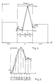
- Fig. 2 the actual values of the velocity has been plotted for the periods i-1, i, i+1 and i-2, as well as the minimum and maximum and average values of the velocity which can be calculated from the distance data.
- the hatched area below the curve corresponds to the distance taken in that period, and this distance is known.
- the velocity run chart will have a linear form as shown in Fig. 3 which can be plotted as a round chart by means of an appropriate chart plotter.
- the line thickness corresponds to half minutes, thus the resolution corresponds to those of conventional tachographs.
- a four bytes long cell of the data memory 32 looks like as follows: in the table F designates the number of pulses of the fuel consumption meter in deciliter units, i.e. the maximum measurable fuel consumption is 8 dl/min, M designates the maximum velocity in km/hour units, in which the available 7 bits allow the recording of at most 128 km/h , m designates the minimum velocity values, also in 7 bits, K designates the state of the ignition key and bits G1 to G3 are freely definable constants, s designates the distance in meters.
- the data can be recorded in 2 km/h units instead of 1 km/h units, whereby a velocity range of 0 to 256 km/h will be storable, however, the resolution will be half as high.
- the widening of the range at the expense of the resolution (accuracy) can be increased by similar methods also in case of known paper disc tachograph systems.
- the correct time data can be recorded in a separate memory cell. e.g. once in a week, whereafter the number of each cell will be equal to the number of the half-minute steps.
- three times higher resolution can be obtained without increasing the number of data to be stored. This can be accomplished if the extreme velocity values stored in the first two bytes be not written in a predetermined order any more (i.e. that the first byte comprise the maximum, while the second one the minimum values), but the order thereof should correspond to their actual order in the associated period. If in a particular period the minimum occurred first, then this should be stored in the first byte and thereafter the maximum and vica versa. In the possession of the detailed data in each period such a storage can be carried out without any difficulties.
- the beginning of an interval in the x-th period that corresponds to the maximum or minimum speed overlaps with the end of the previous (x-1)-th period in a predetermined range.
- the x-th period will be divided in three equal parts which are all 10 seconds long. The first part will be associated with the first extreme value (which is the minimum in the exemplary case) and the second part will be associated with the other extremity (being the maximum in the example of Fig. 4) and the curve will be terminated at the middle of the overlap section between the x-th and (x+1)-th period.
- This kind of approximation might have two limitations.
- the first one lies in that the area defined below the so-obtained curve is not equal to the actual distance taken during this period, while the other one lies in that the changes in speed are higher than allowed by the maximum acceleration or decceleration.
- the location of the points 1 and 2 will be changed along the time axis until the limitations concerning the maximum acceleration and deceleration values are fulfilled.
- the area below the curve can be changed by shifting the point 3 along the vertical (speed) axis. If such changes still prove to be insufficient, then horizontal sections will be inserted at the minimum or maximum values depending on the fact whether the calculated distance is smaller or higher than the actually measured distance value.
- the time scale of the chart should be changed according to the three-times higher accuracy, because if a full circle chart corresponds to e.g. one day, then the mechanical thickness of the lines of the recorder does not allow such a high resolution.
- the correct time scale in that case is 8 hours/full circle.
- the resolution in time can be increased to 4 seconds by means of delta code modulation in the expense of storing one more byte in every half minutes, which results in an increase of 25% in memory storage capacity.
- This embodiment requires the use of the optional units shown in Fig. 1, i.e. the delta code modulator 25 and the assistant memory 33.
- Fig. 5 shows an example for a predictive delta code modulation, in which the above principle is modified by the fact that if in several consecutive sections identical bit values are found, then the steepness of the approximating linear curve is increased (doubled) or decreased (halved).
- Fig. 5 the linear approximating function of eight intervals of a 30 second long period was plotted by full line and the actual curve was shown with dashed line.
- the content of the memory cell corresponding to the intervals a,b,c,d,e,f,g and h can be seen below the associated intervals.
- the actual curve is still above the approximating function, therefore the approximation continues with a double steepness.
- the condition changes which persists until the end of the interval f, therefore the approximation is gradually decreased whereafter it is increased and decreased.
- the delta code modulation can express the changes only within a predetermined error range, since the data memory 32 will continue comprising the extreme speed values and the distance value, thus these values can also be taken into account at the iteration.
- the operation of the delta code modulator has become clear.
- the evaluation of the stored data takes place in central data processing locations by means of appropriate data processing equipment.
- the present invention is directed therefore primarily to the delivery and storage of data which can be reconstructed with sufficient accuracy.
- a further characteristic feature of the apparatus according to the invention lies in the way how the stored data can be transferred to data processing centres.
- the fact that the whole content of the memory unit 30 will be shifted forward by one step in each sampling cycle results in the continuous refreshment of the stored information which can correspond e.g. to the data collected in the last two weeks.
- this readout step is carried out by copying the content of the memory unit 30 in an appropriate outer memory coupled to the apparatus. This copy operation can be performed by connecting the data and address lines of the outer memory to corresponding data and address buses of the microcomputer 20, and reading the data in the outer memory.
Abstract
Description
- The invention relates to a method for storing run data of a vehicle in the memory of an electronic tachograph and displaying these data with a predetermined resolution, in which the movement of the vehicle is sensed by means of a road sensor, digital distance and velocity data are provided from the sensed signals proportional to the advance of the vehicle and the momentary velocity, respectively and these digital data are read in subsequent cells of a data memory of the tachograph in predetermined regular periods.
- The invention relates also to an apparatus for carrying out the method which comprises an input block with inputs coupled to pulse lines of a road sensor and to static signal line, the input block comprises signal forming circuits, a pulse generator and a frequency meter with first input connected to the pulse generator and second input connected to the signal forming circuits associated with the pulse lines, a microcomputer connected to the output of the input block and a memory unit coupled to the microcomputer.
- In our Hungarian patent published on August 28, 1986 and having the application number 4841/84 entitled "electronic tachograph" the conditions for the reliable implementation of an electronic tachograph were discussed including the protection of the memory against disturbances in the power supply and against any possible erroneous processor operation. The patent dealt also with the reading of the stored data by means of light emitting diodes and with the questions of identification. These aspects are important for the implementation of the tachograph function, but it has also a similarly high significance how the large amount of information should be stored to provide an optimum utilization of the memory. The sparing with the available memory capacity forms not only an economic question, but the amount of information that can be stored defines the length of operation of the tachograph without the risk of data losses and without the need for reading out the stored data. Nowadays the storage of data from 1 or two weeks of running time forms a general requirement.
- Although a number of sampling and data compression methods are known, the analysis thereof has shown that most of them are connected with problems when applied for the realization of a tachograph function.
- In a known way of compressed data storage only changes in the sensed variable are recorded together with the associated time data. This method enables a compressed data recording if the sensed process is sufficiently slow. In vehicles, however, this condition cannot be met, the speed of the vehicle can vary within wide limits therefore such a method cannot be used.
- The generally accepted sampling technique should take into account the frequent changes in the velocity, therefore the true reproduction of the velocity-time curve would require a very frequent sampling and the storage of the sampled data. The storage of such an amount of information would be rather redundant.
- In case of using a delta code modulation each sampling would be associated with 1 bit of information only, which means a decreased amount of information to be stored. From these information the changes in the vehicle speed can be reconstructed. The problem lies here also in the required high number of sampling points, since the speed of the vehicle can be changed in 10 to 20 seconds even up to 60 km/hours, therefore the signal reproduction would require a sampling in every 1 or 2 seconds. In view of the full operational period of about two weeks such a sampling would still require a considerably high storage capacity.
- In addition to the appropriate data storage a further problem is connected with the reading out of this information. In a number of conventional data recording equipment the data carrier which stores the information (casette or memory) is removed and transported to a central location for reading out the stored information. If the data carrier is injured during the transport, the important information can get lost. A further problem arises from the possibility that the single data carrier can be manipulated if they can be accessed by unauthorized persons.
- A further requirement can be imposed on an apparatus which aims at implementing the tachograph function electronically, and this lies in the exact reconstruction of the run data just preceding an accident. The term "exact" intends to cover the reconstruction of the velocity-time curve with an accuracy being one or two orders of magnitude higher than the accuracy of data readable from the tachograph chart.
- From the DE-A 3 405 757 an apparatus is known, which is capable to record electronically relevant information about an accident, such as velocity and traveled distance of the vehicle. The information being relevant for the accident are sensed by road- and acceleration sensors, processed by means of a microprocessor and stored in a memory with such a rate, that the relevant information can be retrieved from the memory with a resolution required for a proper reconstruction of the accident. For this reconstruction, sampling of the signals of the sensors with a period time falling typically in the millisecond range and storing the sampled and processed information in the memory are necessary. Because of the high sampling rate and the high amount of information to be stored, information only of about 60 seconds before the accident can be stored in the memory of the apparatus.
- The object of the invention is to provide a method and an apparatus for carrying out the same, which can record information which is at least equivalent with the one stored in conventional tachographs using paper disc but which has an economic utilization of the available memory and which is capable of implementing at least certain ones of the aforementioned additional requirements.
- The invention is based on the recognition that the thickness of the lines in the charts of tachographs using paper discs limit the resolution in time to about half minute, therefore it is sufficient to store data in such a rate, but in each half minute period it is important to know the extreme values of the velocity.
- According to the invention data representing the velocity and distance taken by the vehicle are read in subsequent cells of an accident memory which has a substantially smaller storage capacity than a data memory and stores the run data in a first rate substantially higher than a sampling rate associated with the prescribed accuracy, and the maximum and minimum values of the velocity and the value of said distance are determined during periods following each other with the sampling rate, and at least said minimum and maximum values of the velocity data and the distance value are entered in the data memory in each sampling period, and the content of the accident memory is shifted forward with said first rate and the content of the data memory is shifted forward with said sampling rate.
- In a preferable embodiment the reading in the accident memory occurs when a predetermined distance e.g. 2 meters has been taken by the vehicle, and as many data are stored in the accident memory as required for the reconstruction of an accident e.g. which correspond to a distance of about 500 meters.
- A substantial increase can be reached in the resolution if the extreme values of the velocity are stored in the data memory in the order as they actually follow each other in the associated period.
- The resolution can further be increased by using an additional delta code modulation.
- In a further preferable embodiment for the retrieval of the stored data at a central location the content of the memories but at least that of the data memory is copied in a data storage means in such a way that the content of the memories remains unchanged during the copying operation.
- The apparatus for carrying out the method is defined in
claim 7. - In a preferable embodiment the memory unit comprises an assistant memory with data bus and address bus coupled to a delta code modulator which is implemented in the microcomputer.
- The high sampling rate in the accident memory enables the determination of the extreme values of the velocity in the correct order during the half minute intervals, which facilitates the effective and dense data storage and the reconstruction of any accident.
- The invention will now be described in connection with preferable embodiments thereof, in which reference will be made to the accompanying drawings. In the drawing:
- Fig. 1
- shows the functional block diagram of the apparatus according to the invention,
- Fig. 2
- is a velocity-time curve with enlarged time scale,
- Fig. 3
- is a diagram corresponding to Fig. 2 with a compressed time scale,
- Fig. 4
- is a diagram illustrating the generation of a higher resolution, and
- Fig. 5
- is a diagram illustrating the delta code modulation.
- Figure 1. shows the functional block diagram of the apparatus according to an embodiment of the invention which comprises three main parts such as
input block 12,microcomputer 20 andmemory unit 30.Input block 12 receives throughpulse line 10 pulses generated by a road sensor in response to actual movement of the vehicle in which the apparatus is arranged and further pulses generated by a fuel consumption sensor. In addition to these pulse signals certain status data are also required for the correct run recording (such data are e.g. the position of the ignition key, the on- or off-state of the brake lamps and in certain cases identification data of the driver). Theinput block 12 receives these status data through static signal lines 11.Pulse lines 10 are coupled throughsignal forming circuits 13 to gate inputs offrequency meters 15.Frequency meters 15 have pulse inputs receiving constant frequency output pulses frompulse generator 14. Thefrequency meters 15 pass the clock pulses of thepulse generator 14 to their outputs during the time periods defined between consecutive pulses appearing at their respective gating inputs, therefore the number of the pulses at the output of the frequency meters corresponds to the time elapsed between respective gating pulses. The number of the pulse-sensing channels is equal to the number of the quantities which should be measured, e.g. in the exemplary embodiment one channel is associated with the measurement of the distance covered by the vehicle (and with the velocity determined from the distance), while another channel is used for measuring the fuel consumption. The static signal lines 11 are coupled to inputs of furthersignal forming circuits 16. - The
microcomputer 20 can be implemented by a general purpose microprocessor and Fig. 1 shows only those of its functional blocks which are required for understanding the operation.Data register 21 is used to receive output signals of theinput block 21. Themicrocomputer 20 comprises a clock generator 24 which delivers output pulses e.g. in 30 second intervals, an accidentmemory address controller 22, a data compressor andmemory controller 23 and a delta code modulator 25. - The
memory unit 30 consists of three parts i.e.accident memory 31,data memory 32 andassistant memory 33. This latter memory is required only if higher accuracy requirements are imposed on the data storage. -
Address lines 34 of theaccident memory 31 are connected to the output of the accidentmemory address controller 22 and data lines of theaccident memory 31 are coupled to data bus of themicrocomputer 20. Predetermined outputs of the data register 21 are connected throughline 29 to data lines of theaccident memory 31 and afurther output 28 thereof is connected to the input of the delta code modulator 25. The output of the clock generator 24 is coupled throughline 26 to the delta code modulator 25 and throughline 27 to the data compressor andmemory controller 23. - Data lines of the
accident memory 31 are coupled throughbus 35 to the input of the data compressor andmemory controller 23 and the output of this latter is coupled todata bus 36 andaddress bus 37 of thedata memory 32. Data bus 38 andaddress bus 39 of theassistant memory 33 are coupled to the delta code modulator 25. - The operation of the apparatus according to the invention will be explained in connection with the time diagrams of Figs. 2 to 5.
- The most general task lies in the implementation of the function of a tachograph. This requires a data storage which comprises sufficient amount of information on the basis of which a tachograph chart can be plotted. The line thickness of recorders used generally in tachographs renders the distinction of events longer than 30 seconds possible, i.e. the resolution in time is not better than 30 seconds. In accordance therewith the clock generator 24 delivers clock pulses in 30 second intervals.
- When the vehicle moves, the road sensor generates respective gating pulses after every 2 meters of movement. The data register 21 will store the number of pulses of the
pulse generator 14 occurring in the time required for the completion of the distance of 2 meters. Themicrocomputer 20 calculates the velocity v of the vehicle for each path sections of 2 meters and writes these velocity data in successive cells of theaccident memory 31 having consecutive addresses. Seven bits are generally sufficient for the storage of the velocity data, whereby the velocity range of 0 to 128 km/hour can be recorded with an accuracy of 1 km/h. Theaccident memory 31 comprises 256 cells and it stores the data associated with the last 512 meters of the route with a high accuracy. When all cells of theaccident memory 31 have been filled, the accidentmemory address controller 22 directs the next new data to be written in the first cell and it shifts the content of thememory 31 forward by one cell. The oldest data comprised in the last cell of the memory will then be lost. - A data storage with such a high resolution is not necessary for the long term run recording, and for the reconstruction of an accident the retrieval of the data associated with the last few hundred meters is sufficient and the capacity of the
accident memory 31 has been chosen accordingly. - For the long term storage of the run data the efficient utilization of the available capacity of the
data memory 32 and the necessary run reconstruction require and optimum amount of data compression. In each 30 second period themicrocomputer 20 knows the velocity data determined in 2 meter road sections. From this information the data compressor andmemory controller 23 determines for each period the maximum and minimum speed and the distance made by the vehicle and it writes these data to the cell at the always actual first available address of thedata memory 32, then shifts further the whole content of the memory by one step. It can be appreciated that based on the data stored in theaccident memory 31, themicrocomputer 20 knows the order of the maximum and minimum speed in every 30 second period. - In Fig. 2 the actual values of the velocity has been plotted for the periods i-1, i, i+1 and i-2, as well as the minimum and maximum and average values of the velocity which can be calculated from the distance data. In the period i+2 the hatched area below the curve corresponds to the distance taken in that period, and this distance is known. If in the respective periods only the two extreme velocity values are stored, then the velocity run chart will have a linear form as shown in Fig. 3 which can be plotted as a round chart by means of an appropriate chart plotter. The line thickness corresponds to half minutes, thus the resolution corresponds to those of conventional tachographs.
- It is preferable if in each half minute period 4 bytes of information is stored. In a preferable embodiment a four bytes long cell of the
data memory 32 looks like as follows:
in the table F designates the number of pulses of the fuel consumption meter in deciliter units, i.e. the maximum measurable fuel consumption is 8 dl/min, M designates the maximum velocity in km/hour units, in which the available 7 bits allow the recording of at most 128 km/h , m designates the minimum velocity values, also in 7 bits, K designates the state of the ignition key and bits G₁ to G₃ are freely definable constants, s designates the distance in meters. - If the maximum value of 128 km/h is not sufficient, then the data can be recorded in 2 km/h units instead of 1 km/h units, whereby a velocity range of 0 to 256 km/h will be storable, however, the resolution will be half as high. The widening of the range at the expense of the resolution (accuracy) can be increased by similar methods also in case of known paper disc tachograph systems.
- The correct time data can be recorded in a separate memory cell. e.g. once in a week, whereafter the number of each cell will be equal to the number of the half-minute steps.
- In a preferable embodiment of the invention three times higher resolution can be obtained without increasing the number of data to be stored. This can be accomplished if the extreme velocity values stored in the first two bytes be not written in a predetermined order any more (i.e. that the first byte comprise the maximum, while the second one the minimum values), but the order thereof should correspond to their actual order in the associated period. If in a particular period the minimum occurred first, then this should be stored in the first byte and thereafter the maximum and vica versa. In the possession of the detailed data in each period such a storage can be carried out without any difficulties.
- If the extreme speed values are stored in a correct order, then more accurate run information can be obtained from these data if further information characteristic to certain properties of the vehicle (such as maximum acceleration and decceleration) are also taken into account (of course, by means of the microcomputer). This method will be illustrated in Fig. 4.
- The beginning of an interval in the x-th period that corresponds to the maximum or minimum speed overlaps with the end of the previous (x-1)-th period in a predetermined range. As a first step of iteration it will be supposed that the curve that defines the actual variation of the speed falls in the middle of this overlapping range, then the x-th period will be divided in three equal parts which are all 10 seconds long. The first part will be associated with the first extreme value (which is the minimum in the exemplary case) and the second part will be associated with the other extremity (being the maximum in the example of Fig. 4) and the curve will be terminated at the middle of the overlap section between the x-th and (x+1)-th period.
- This kind of approximation might have two limitations. The first one lies in that the area defined below the so-obtained curve is not equal to the actual distance taken during this period, while the other one lies in that the changes in speed are higher than allowed by the maximum acceleration or decceleration. In the latter case the location of the
points - If still higher resolution is required, then the resolution in time can be increased to 4 seconds by means of delta code modulation in the expense of storing one more byte in every half minutes, which results in an increase of 25% in memory storage capacity. This embodiment requires the use of the optional units shown in Fig. 1, i.e. the delta code modulator 25 and the
assistant memory 33. - The essence of this method lies in that the analogue velocity-time curve will be approximated by linear sections characterized by a predetermined acceleration or deceleration. If at the end moment of such a section the actual speed is higher than the approximated speed, then a bit with
value 1 is stored, while if it is lower, then abit 0 is stored. Fig. 5 shows an example for a predictive delta code modulation, in which the above principle is modified by the fact that if in several consecutive sections identical bit values are found, then the steepness of the approximating linear curve is increased (doubled) or decreased (halved). - In Fig. 5 the linear approximating function of eight intervals of a 30 second long period was plotted by full line and the actual curve was shown with dashed line. The content of the memory cell corresponding to the intervals a,b,c,d,e,f,g and h can be seen below the associated intervals. Following the interval a the actual curve is still above the approximating function, therefore the approximation continues with a double steepness. At the end of the interval c the condition changes which persists until the end of the interval f, therefore the approximation is gradually decreased whereafter it is increased and decreased.
- In spite of the fact that the delta code modulation can express the changes only within a predetermined error range, the approximation will be very accurate, since the
data memory 32 will continue comprising the extreme speed values and the distance value, thus these values can also be taken into account at the iteration. On the basis of Fig. 5, however, the operation of the delta code modulator has become clear. The evaluation of the stored data takes place in central data processing locations by means of appropriate data processing equipment. The present invention is directed therefore primarily to the delivery and storage of data which can be reconstructed with sufficient accuracy. - A further characteristic feature of the apparatus according to the invention lies in the way how the stored data can be transferred to data processing centres. The fact that the whole content of the
memory unit 30 will be shifted forward by one step in each sampling cycle results in the continuous refreshment of the stored information which can correspond e.g. to the data collected in the last two weeks. When the memory is read out its content need not and should not be cleared, and this readout step is carried out by copying the content of thememory unit 30 in an appropriate outer memory coupled to the apparatus. This copy operation can be performed by connecting the data and address lines of the outer memory to corresponding data and address buses of themicrocomputer 20, and reading the data in the outer memory. - This way of information collection enables the safe storage of run data in the original memory unit which will not be lost by the reading out of the information. The data can be checked even after their readout and the information retrieval does not interfere with the internal operation of the apparatus which makes any manipulation with the data impossible.
Claims (8)
- Method for storing run data of a vehicle in the memory of an electronic tachograph and displaying these data with a predetermined resolution, comprising the steps of sensing the movement of the vehicle by means of a road sensor, providing digital distance and velocity data from signals of the sensing step proportional to the advance of the vehicle and the momentary velocity, respectively, reading said digital data in subsequent cells of data memory (32) of the tachograph in predetermined regular periods corresponding to said resolution, characterized in that said data are read in subsequent cells of an accident memory (31) which has a substantially smaller storage capacity than said data memory (32) in a first rate substantially higher than a sampling rate associated with said predetermined regular periods, determining the maximum and minimum values of the velocity and the value of said distance during each of said periods, and in said step of reading in the data memory (32) at least said minimum and maximum values of the velocity data and the distance value are entered, shifting forward the content of the accident memory (31) with said first rate and shifting forward the content of the data memory (32) with said sampling rate.
- The method as claimed in claim 1, characterized in that the reading in said accident memory (31) occurs when a predetermined distance e.g. 2 meters has been taken by the vehicle, and storing as many data in the accident memory (31) as required for the reconstruction of an accident e.g. which are associated with a distance of about 500 meters.
- The method as claimed in claim 1, characterized in that said extreme values of the velocity are stored in the data memory (32) in the order as they actually followed each other in the associated period.
- The method as claimed in claim 1, characterized in that each of said periods is divided in a predetermined number e.g. eight intervals and further comprises the step of approximating the velocity in that period by linear functions according to a delta modulation or to a predictive delta modulation and storing a bit value in each interval which depends on whether the approximated function is higher or lower than the velocity, and reading these bit values in each of said periods in a cell of an assistant memory (33) associated with the cell of the data memory (32) storing the data of this period.
- The method as claimed in claim 1, characterized in that storing in each of said periods an information of four bytes with eight bits in each byte in the data memory (32), a few number of these bits are associated with sampled digital value of the fuel consumption of the vehicle during the associated period and with predetermined other condition data of the vehicle.
- The method as claimed in claim 1, characterized in that said stored data are retrieved by copying the content of said memories in a data storage means in such a way that the content of said memories remains unchanged during the copying operation.
- Apparatus for carrying out the method as claimed in any of claims 1 to 6, comprising an input block (12) having inputs coupled to pulse lines (10) of a road sensor and to static signal line (11), the input block (12) comprises signal forming circuits (13, 16), a pulse generator (14) and a frequency meter (15) with first input connected to the pulse generator (14) and second input connected to the signal forming circuit (13) associated with the pulse lines (10), a microcomputer (20) connected to the output of the input block (12) to provide distance and velocity data from signals of the road sensor and a memory unit (30) coupled to the microcomputer (20), characterized in that the memory unit (30) comprises an accident memory (31) with address lines (34) and data bus (35) coupled to memory address controller (22) associated with the microcomputer (20), data memory (32) with data bus (36) and address bus (37) coupled to a data compressor and memory controller (23) belonging to the microcomputer (20) and the microcomputer (20) comprises a clock generator (24) and an input data register (21), wherein the accident memory (31) has a substantially smaller storage capacity than the data memory (32), the data provided by the microcomputer (20) are entered into the accident memory (31) with a first rate, at least the maximum and minimum values of the velocity and the distance values provided by the microcomputer (20) from the instantaneous data in predetermined regular periods determined by the clock generator (24) and compressed by the compressor and memory controller (23) are entered into the data memory (32) with a sampling rate being substantially lower than the first rate, and wherein the content of the accident memory (31) is shifted forward with the first rate and the content of the data memory (32) is shifted forward with the sampling rate.
- The apparatus as claimed in claim 7, characterized in that the memory unit (30) comprises an assistant memory (33) with data bus (38) and address bus (39) coupled to a delta code modulator (25) realized in the microcomputer (20).
Priority Applications (1)
| Application Number | Priority Date | Filing Date | Title |
|---|---|---|---|
| AT88900471T ATE96564T1 (en) | 1986-12-29 | 1987-12-29 | METHOD FOR STORING THE RUNNING DATA OF A VEHICLE IN THE MEMORY OF AN ELECTRONIC TACHOGRAPH AND DEVICE FOR CARRYING OUT THESE METHOD. |
Applications Claiming Priority (2)
| Application Number | Priority Date | Filing Date | Title |
|---|---|---|---|
| HU865495A HU206415B (en) | 1986-12-29 | 1986-12-29 | Method for recording travel data of a motor vehicle into the memory of electronic tachograph, and device for implementing said method |
| HU549586 | 1986-12-29 |
Publications (2)
| Publication Number | Publication Date |
|---|---|
| EP0352260A1 EP0352260A1 (en) | 1990-01-31 |
| EP0352260B1 true EP0352260B1 (en) | 1993-10-27 |
Family
ID=10970364
Family Applications (1)
| Application Number | Title | Priority Date | Filing Date |
|---|---|---|---|
| EP88900471A Expired - Lifetime EP0352260B1 (en) | 1986-12-29 | 1987-12-29 | Method for storing run data of a vehicule in the memory of an electronic tachograph and apparatus for carrying out the method |
Country Status (7)
| Country | Link |
|---|---|
| US (1) | US4987541A (en) |
| EP (1) | EP0352260B1 (en) |
| AU (1) | AU613891B2 (en) |
| CA (1) | CA1301292C (en) |
| DE (1) | DE3787975D1 (en) |
| HU (1) | HU206415B (en) |
| WO (1) | WO1988005196A1 (en) |
Families Citing this family (54)
| Publication number | Priority date | Publication date | Assignee | Title |
|---|---|---|---|---|
| US5239470A (en) * | 1990-02-08 | 1993-08-24 | Yazaki Corporation | Data recording method and device |
| US5267159A (en) * | 1990-09-13 | 1993-11-30 | Neall Donald L O | Mileage recording and display apparatus |
| JP2884850B2 (en) * | 1991-10-11 | 1999-04-19 | 日産自動車株式会社 | Automotive data recorder |
| DE4136968C1 (en) * | 1991-11-11 | 1992-11-12 | Mannesmann Kienzle Gmbh, 7730 Villingen-Schwenningen, De | |
| DE4218397A1 (en) * | 1992-06-04 | 1993-12-09 | Mannesmann Kienzle Gmbh | Short path registration device for motor vehicles |
| JP3309437B2 (en) * | 1992-08-19 | 2002-07-29 | 株式会社デンソー | Vehicle self-diagnosis device |
| US5325082A (en) * | 1992-11-19 | 1994-06-28 | Rodriguez Juan C | Comprehensive vehicle information storage system |
| US5438513A (en) * | 1993-11-19 | 1995-08-01 | Chrysler Corporation | Automotive electronics test system |
| US5600558A (en) * | 1994-08-12 | 1997-02-04 | Caterpillar Inc. | Data exception reporting system |
| US5857159A (en) * | 1994-08-12 | 1999-01-05 | Caterpillar Inc. | Data recording and display system |
| US7190284B1 (en) * | 1994-11-16 | 2007-03-13 | Dye Thomas A | Selective lossless, lossy, or no compression of data based on address range, data type, and/or requesting agent |
| US6002411A (en) * | 1994-11-16 | 1999-12-14 | Interactive Silicon, Inc. | Integrated video and memory controller with data processing and graphical processing capabilities |
| US8140358B1 (en) | 1996-01-29 | 2012-03-20 | Progressive Casualty Insurance Company | Vehicle monitoring system |
| US6868386B1 (en) | 1996-01-29 | 2005-03-15 | Progressive Casualty Insurance Company | Monitoring system for determining and communicating a cost of insurance |
| US8090598B2 (en) * | 1996-01-29 | 2012-01-03 | Progressive Casualty Insurance Company | Monitoring system for determining and communicating a cost of insurance |
| US5797134A (en) * | 1996-01-29 | 1998-08-18 | Progressive Casualty Insurance Company | Motor vehicle monitoring system for determining a cost of insurance |
| EP0871147A3 (en) * | 1997-04-09 | 2001-04-18 | Volkswagen Aktiengesellschaft | Method for storing accident related data of a motor vehicle and accident data memory |
| US6389340B1 (en) * | 1998-02-09 | 2002-05-14 | Gary A. Rayner | Vehicle data recorder |
| US7129860B2 (en) * | 1999-01-29 | 2006-10-31 | Quickshift, Inc. | System and method for performing scalable embedded parallel data decompression |
| DE10042005A1 (en) * | 2000-08-26 | 2002-03-07 | Bosch Gmbh Robert | Method and device for recording scanned information, in particular operating data of a motor vehicle |
| DE10046696A1 (en) * | 2000-09-21 | 2002-04-11 | Bosch Gmbh Robert | Vehicle data recording method has data recording density decreasing continuously from momentary detection time point |
| CA2531662C (en) | 2003-07-07 | 2016-04-26 | Sensomatix Ltd. | Traffic information system |
| US7774112B2 (en) * | 2004-09-27 | 2010-08-10 | Teledyne Technologies Incorporated | System and method for flight data recording |
| US10878646B2 (en) | 2005-12-08 | 2020-12-29 | Smartdrive Systems, Inc. | Vehicle event recorder systems |
| US20070150138A1 (en) | 2005-12-08 | 2007-06-28 | James Plante | Memory management in event recording systems |
| US9201842B2 (en) | 2006-03-16 | 2015-12-01 | Smartdrive Systems, Inc. | Vehicle event recorder systems and networks having integrated cellular wireless communications systems |
| US8996240B2 (en) | 2006-03-16 | 2015-03-31 | Smartdrive Systems, Inc. | Vehicle event recorders with integrated web server |
| US7536457B2 (en) * | 2006-05-08 | 2009-05-19 | Drivecam, Inc. | System and method for wireless delivery of event data |
| US7804426B2 (en) * | 2006-05-08 | 2010-09-28 | Drivecam, Inc. | System and method for selective review of event data |
| US7659827B2 (en) * | 2006-05-08 | 2010-02-09 | Drivecam, Inc. | System and method for taking risk out of driving |
| US20080043736A1 (en) * | 2006-08-18 | 2008-02-21 | Drivecam, Inc. | Data Transfer System and Method |
| US20070257782A1 (en) * | 2006-05-08 | 2007-11-08 | Drivecam, Inc. | System and Method for Multi-Event Capture |
| US8314708B2 (en) * | 2006-05-08 | 2012-11-20 | Drivecam, Inc. | System and method for reducing driving risk with foresight |
| US8373567B2 (en) * | 2006-05-08 | 2013-02-12 | Drivecam, Inc. | System and method for identifying non-event profiles |
| US9836716B2 (en) | 2006-05-09 | 2017-12-05 | Lytx, Inc. | System and method for reducing driving risk with hindsight |
| DE102006023136A1 (en) * | 2006-05-17 | 2007-11-22 | Siemens Ag | Method and device for operating a digital tachograph and a data carrier |
| US8649933B2 (en) | 2006-11-07 | 2014-02-11 | Smartdrive Systems Inc. | Power management systems for automotive video event recorders |
| US8989959B2 (en) | 2006-11-07 | 2015-03-24 | Smartdrive Systems, Inc. | Vehicle operator performance history recording, scoring and reporting systems |
| US8868288B2 (en) | 2006-11-09 | 2014-10-21 | Smartdrive Systems, Inc. | Vehicle exception event management systems |
| US8239092B2 (en) | 2007-05-08 | 2012-08-07 | Smartdrive Systems Inc. | Distributed vehicle event recorder systems having a portable memory data transfer system |
| JP2009225260A (en) * | 2008-03-18 | 2009-10-01 | Fujitsu Ten Ltd | Control apparatus, control method, vehicle control device, and vehicle control system |
| JP4955625B2 (en) * | 2008-08-01 | 2012-06-20 | 株式会社デンソー | Driving advice providing device, driving diagnosis device |
| JP5198969B2 (en) * | 2008-08-01 | 2013-05-15 | 株式会社デンソー | Driving diagnosis information providing device and driving diagnosis information providing system |
| US20100123779A1 (en) * | 2008-11-18 | 2010-05-20 | Dennis Michael Snyder | Video recording system for a vehicle |
| US9916625B2 (en) | 2012-02-02 | 2018-03-13 | Progressive Casualty Insurance Company | Mobile insurance platform system |
| US8489433B2 (en) | 2010-07-29 | 2013-07-16 | Insurance Services Office, Inc. | System and method for estimating loss propensity of an insured vehicle and providing driving information |
| US9728228B2 (en) | 2012-08-10 | 2017-08-08 | Smartdrive Systems, Inc. | Vehicle event playback apparatus and methods |
| RU2548618C2 (en) * | 2013-05-07 | 2015-04-20 | Федеральное государственное бюджетное образовательное учреждение высшего профессионального образования "Кубанский государственный технологический университет" (ФГБОУ ВПО "КубГТУ") | Network block to monitor power supply quality |
| US9501878B2 (en) | 2013-10-16 | 2016-11-22 | Smartdrive Systems, Inc. | Vehicle event playback apparatus and methods |
| US9610955B2 (en) | 2013-11-11 | 2017-04-04 | Smartdrive Systems, Inc. | Vehicle fuel consumption monitor and feedback systems |
| US8892310B1 (en) | 2014-02-21 | 2014-11-18 | Smartdrive Systems, Inc. | System and method to detect execution of driving maneuvers |
| US9663127B2 (en) | 2014-10-28 | 2017-05-30 | Smartdrive Systems, Inc. | Rail vehicle event detection and recording system |
| US11069257B2 (en) | 2014-11-13 | 2021-07-20 | Smartdrive Systems, Inc. | System and method for detecting a vehicle event and generating review criteria |
| US9679420B2 (en) | 2015-04-01 | 2017-06-13 | Smartdrive Systems, Inc. | Vehicle event recording system and method |
Family Cites Families (10)
| Publication number | Priority date | Publication date | Assignee | Title |
|---|---|---|---|---|
| DE2752991A1 (en) * | 1977-11-28 | 1979-05-31 | Deuta Werke Gmbh | METHOD AND DEVICE FOR THE TEMPORARY STORAGE OF VALUES ABOUT IN PARTICULAR OPERATION, MOVEMENT AND OPERATION OF VEHICLES |
| US4533962A (en) * | 1982-08-05 | 1985-08-06 | Decker Ronald R | Vehicle performance detection and recording apparatus |
| DE3248192A1 (en) * | 1982-08-25 | 1984-03-01 | Roland 7770 Überlingen Heubeck | Device for recording data of a motor vehicle before an accident |
| DE3247910A1 (en) * | 1982-12-24 | 1984-06-28 | SWF-Spezialfabrik für Autozubehör Gustav Rau GmbH, 7120 Bietigheim-Bissingen | Circuit arrangement for data storage in motor vehicles |
| DE3405757A1 (en) * | 1983-02-26 | 1984-10-04 | Edmund 7016 Gerlingen Zottnik | ACCIDENT RECORDER |
| US4575454A (en) * | 1983-04-18 | 1986-03-11 | The Dow Chemical Company | Metal ion control agents based on dicyclopentadiene derivatives |
| DE3341471A1 (en) * | 1983-11-17 | 1985-05-30 | SWF Auto-Electric GmbH, 7120 Bietigheim-Bissingen | Instrument for motor vehicles |
| CA1247743A (en) * | 1985-01-24 | 1988-12-28 | Izuru Morita | Operation data recording system |
| JPS63233491A (en) * | 1987-03-20 | 1988-09-29 | 株式会社トキメック | Operation recorder |
| US4817118A (en) * | 1987-06-29 | 1989-03-28 | Step Engineering | Mobile incident logger |
-
1986
- 1986-12-29 HU HU865495A patent/HU206415B/en not_active IP Right Cessation
-
1987
- 1987-12-24 CA CA000555401A patent/CA1301292C/en not_active Expired
- 1987-12-29 WO PCT/HU1987/000061 patent/WO1988005196A1/en active IP Right Grant
- 1987-12-29 AU AU10845/88A patent/AU613891B2/en not_active Ceased
- 1987-12-29 US US07/381,687 patent/US4987541A/en not_active Expired - Fee Related
- 1987-12-29 DE DE88900471T patent/DE3787975D1/en not_active Expired - Lifetime
- 1987-12-29 EP EP88900471A patent/EP0352260B1/en not_active Expired - Lifetime
Also Published As
| Publication number | Publication date |
|---|---|
| EP0352260A1 (en) | 1990-01-31 |
| HU206415B (en) | 1992-10-28 |
| AU1084588A (en) | 1988-07-27 |
| DE3787975D1 (en) | 1993-12-02 |
| WO1988005196A1 (en) | 1988-07-14 |
| CA1301292C (en) | 1992-05-19 |
| US4987541A (en) | 1991-01-22 |
| HUT49226A (en) | 1989-08-28 |
| AU613891B2 (en) | 1991-08-15 |
Similar Documents
| Publication | Publication Date | Title |
|---|---|---|
| EP0352260B1 (en) | Method for storing run data of a vehicule in the memory of an electronic tachograph and apparatus for carrying out the method | |
| CA1136276A (en) | Vehicular data handling and control system | |
| US3792445A (en) | Vehicle data recording system | |
| US4533962A (en) | Vehicle performance detection and recording apparatus | |
| US4586138A (en) | Route profile analysis system and method | |
| US4638289A (en) | Accident data recorder | |
| JPH0512852Y2 (en) | ||
| US3864731A (en) | Vehicle data recorder employing data compression | |
| US5379219A (en) | Vehicle digital movement data recording apparatus | |
| CA1238976A (en) | Electronic odometer | |
| US4692882A (en) | Apparatus for recording the speed of a vehicle | |
| GB2081909A (en) | Digital tachograph | |
| US4250487A (en) | Vehicle speed recorder | |
| JP2001502054A (en) | Navigation system | |
| CA2129402C (en) | Wheel spin speed processing system for multiple-axle railway vehicles | |
| JPH0542602B2 (en) | ||
| EP1007979A1 (en) | A method for calibrating a speed or distance measuring device | |
| JPS60189091A (en) | Operation recorder for vehicle | |
| JP2772353B2 (en) | Vehicle driving condition recording method and device | |
| JP2511165B2 (en) | Speed data recording method and device | |
| JPH0353673B2 (en) | ||
| JP2553370B2 (en) | Vehicle operation recording device | |
| JPH087764B2 (en) | Vehicle driving condition recording method and device | |
| JP2502160B2 (en) | Data recording method and device | |
| JPS6132743B2 (en) |
Legal Events
| Date | Code | Title | Description |
|---|---|---|---|
| PUAI | Public reference made under article 153(3) epc to a published international application that has entered the european phase |
Free format text: ORIGINAL CODE: 0009012 |
|
| 17P | Request for examination filed |
Effective date: 19890628 |
|
| AK | Designated contracting states |
Kind code of ref document: A1 Designated state(s): AT BE CH DE FR GB IT LI LU NL SE |
|
| 17Q | First examination report despatched |
Effective date: 19920527 |
|
| GRAA | (expected) grant |
Free format text: ORIGINAL CODE: 0009210 |
|
| AK | Designated contracting states |
Kind code of ref document: B1 Designated state(s): AT BE CH DE FR GB IT LI LU NL SE |
|
| PG25 | Lapsed in a contracting state [announced via postgrant information from national office to epo] |
Ref country code: IT Free format text: LAPSE BECAUSE OF FAILURE TO SUBMIT A TRANSLATION OF THE DESCRIPTION OR TO PAY THE FEE WITHIN THE PRE;WARNING: LAPSES OF ITALIAN PATENTS WITH EFFECTIVE DATE BEFORE 2007 MAY HAVE OCCURRED AT ANY TIME BEFORE 2007. THE CORRECT EFFECTIVE DATE MAY BE DIFFERENT FROM THE ONE RECORDED.SCRIBED TIME-LIMIT Effective date: 19931027 Ref country code: AT Effective date: 19931027 Ref country code: BE Effective date: 19931027 Ref country code: SE Effective date: 19931027 Ref country code: NL Effective date: 19931027 Ref country code: DE Effective date: 19931027 Ref country code: FR Effective date: 19931027 Ref country code: LI Effective date: 19931027 Ref country code: CH Effective date: 19931027 |
|
| REF | Corresponds to: |
Ref document number: 96564 Country of ref document: AT Date of ref document: 19931115 Kind code of ref document: T |
|
| REF | Corresponds to: |
Ref document number: 3787975 Country of ref document: DE Date of ref document: 19931202 |
|
| PG25 | Lapsed in a contracting state [announced via postgrant information from national office to epo] |
Ref country code: LU Free format text: LAPSE BECAUSE OF NON-PAYMENT OF DUE FEES Effective date: 19931231 |
|
| PG25 | Lapsed in a contracting state [announced via postgrant information from national office to epo] |
Ref country code: GB Effective date: 19940127 |
|
| REG | Reference to a national code |
Ref country code: CH Ref legal event code: PL |
|
| EN | Fr: translation not filed | ||
| NLV1 | Nl: lapsed or annulled due to failure to fulfill the requirements of art. 29p and 29m of the patents act | ||
| PLBE | No opposition filed within time limit |
Free format text: ORIGINAL CODE: 0009261 |
|
| STAA | Information on the status of an ep patent application or granted ep patent |
Free format text: STATUS: NO OPPOSITION FILED WITHIN TIME LIMIT |
|
| GBPC | Gb: european patent ceased through non-payment of renewal fee |
Effective date: 19940127 |
|
| 26N | No opposition filed |