EP0353040A2 - Electromagnetic identification system - Google Patents
Electromagnetic identification system Download PDFInfo
- Publication number
- EP0353040A2 EP0353040A2 EP89307582A EP89307582A EP0353040A2 EP 0353040 A2 EP0353040 A2 EP 0353040A2 EP 89307582 A EP89307582 A EP 89307582A EP 89307582 A EP89307582 A EP 89307582A EP 0353040 A2 EP0353040 A2 EP 0353040A2
- Authority
- EP
- European Patent Office
- Prior art keywords
- magnetic
- orientated
- tag
- magnetic particles
- magnetically
- Prior art date
- Legal status (The legal status is an assumption and is not a legal conclusion. Google has not performed a legal analysis and makes no representation as to the accuracy of the status listed.)
- Granted
Links
Images

Classifications
-
- G—PHYSICS
- G08—SIGNALLING
- G08B—SIGNALLING OR CALLING SYSTEMS; ORDER TELEGRAPHS; ALARM SYSTEMS
- G08B13/00—Burglar, theft or intruder alarms
- G08B13/22—Electrical actuation
- G08B13/24—Electrical actuation by interference with electromagnetic field distribution
- G08B13/2402—Electronic Article Surveillance [EAS], i.e. systems using tags for detecting removal of a tagged item from a secure area, e.g. tags for detecting shoplifting
- G08B13/2405—Electronic Article Surveillance [EAS], i.e. systems using tags for detecting removal of a tagged item from a secure area, e.g. tags for detecting shoplifting characterised by the tag technology used
- G08B13/2408—Electronic Article Surveillance [EAS], i.e. systems using tags for detecting removal of a tagged item from a secure area, e.g. tags for detecting shoplifting characterised by the tag technology used using ferromagnetic tags
- G08B13/2411—Tag deactivation
-
- G—PHYSICS
- G06—COMPUTING; CALCULATING OR COUNTING
- G06K—GRAPHICAL DATA READING; PRESENTATION OF DATA; RECORD CARRIERS; HANDLING RECORD CARRIERS
- G06K19/00—Record carriers for use with machines and with at least a part designed to carry digital markings
- G06K19/02—Record carriers for use with machines and with at least a part designed to carry digital markings characterised by the selection of materials, e.g. to avoid wear during transport through the machine
-
- G—PHYSICS
- G06—COMPUTING; CALCULATING OR COUNTING
- G06K—GRAPHICAL DATA READING; PRESENTATION OF DATA; RECORD CARRIERS; HANDLING RECORD CARRIERS
- G06K19/00—Record carriers for use with machines and with at least a part designed to carry digital markings
- G06K19/06—Record carriers for use with machines and with at least a part designed to carry digital markings characterised by the kind of the digital marking, e.g. shape, nature, code
- G06K19/06187—Record carriers for use with machines and with at least a part designed to carry digital markings characterised by the kind of the digital marking, e.g. shape, nature, code with magnetically detectable marking
-
- G—PHYSICS
- G08—SIGNALLING
- G08B—SIGNALLING OR CALLING SYSTEMS; ORDER TELEGRAPHS; ALARM SYSTEMS
- G08B13/00—Burglar, theft or intruder alarms
- G08B13/22—Electrical actuation
- G08B13/24—Electrical actuation by interference with electromagnetic field distribution
- G08B13/2402—Electronic Article Surveillance [EAS], i.e. systems using tags for detecting removal of a tagged item from a secure area, e.g. tags for detecting shoplifting
- G08B13/2405—Electronic Article Surveillance [EAS], i.e. systems using tags for detecting removal of a tagged item from a secure area, e.g. tags for detecting shoplifting characterised by the tag technology used
- G08B13/2414—Electronic Article Surveillance [EAS], i.e. systems using tags for detecting removal of a tagged item from a secure area, e.g. tags for detecting shoplifting characterised by the tag technology used using inductive tags
- G08B13/2417—Electronic Article Surveillance [EAS], i.e. systems using tags for detecting removal of a tagged item from a secure area, e.g. tags for detecting shoplifting characterised by the tag technology used using inductive tags having a radio frequency identification chip
-
- G—PHYSICS
- G08—SIGNALLING
- G08B—SIGNALLING OR CALLING SYSTEMS; ORDER TELEGRAPHS; ALARM SYSTEMS
- G08B13/00—Burglar, theft or intruder alarms
- G08B13/22—Electrical actuation
- G08B13/24—Electrical actuation by interference with electromagnetic field distribution
- G08B13/2402—Electronic Article Surveillance [EAS], i.e. systems using tags for detecting removal of a tagged item from a secure area, e.g. tags for detecting shoplifting
- G08B13/2428—Tag details
- G08B13/2437—Tag layered structure, processes for making layered tags
- G08B13/2442—Tag materials and material properties thereof, e.g. magnetic material details
Definitions
- This invention relates to electromagnetic tagging apparatus and in particular to magnetic tags for use with electromagnetic identification systems of the kind which can be employed, for example, in electronic article surveillance (E.A.S.), primarily for in-store security, or in access control.
- E.A.S. electronic article surveillance
- Such systems in either environment, utilise an element, frequently referred to a "tag", which influences an electromagnetic field, so causing a disturbance in a characteristic of the field as detected by a detector device.
- the tag needs to exhibit a number of characteristics one of which, especially relevant for in-store usage, is the capability of being readily de-activated by check-out personnel whilst being difficult for a would-be thief to de-activate.
- the element, or tag it is usual for the element, or tag, to contain a strip of highly permeable magnetic material. Such material is easily influenced by a relatively weak interrogating field and caused to generate a number of harmonic frequencies which are readily detected by a suitable detection device. Unless it is proposed to physically fracture or mechanically strain the strip in order to de-activate it, and such activities would place severe limitations upon the form which a tag could take, de-activation is usually achieved by magnetising magnetically hard material disposed in the tag and configured so as to produce, when so magnetised, a series of poles along the length of the strip of highly permeable material. This series of poles alters the magnetic "profile" of the tag, as presented to the interrogating field, and inhibits the generation of the aforementioned harmonics, thus permitting the detection device to distinguish between activated and de-activated tags.
- the magnetically hard material used for de-activation of the tag has been usual hitherto for the magnetically hard material used for de-activation of the tag to be provided either in the form of discontinuous lengths arranged in close proximity to the strip of magnetically soft material, or in continuous lengths similarly disposed.
- de-activation is relatively straightforward for check-out personnel to accomplish, but the same can be said for would-be thieves.
- more care has to be taken by the check-out personnel because the continuous length of magnetically hard material has to be selectively magnetised to produce a pole pattern sufficient to change the electromagnetic profile of the tag, but at the same time de-activation is made more difficult for the would-be thief.
- the present invention seeks to provide an improved tag which can be deactivated easily by check out or access security personnel but for which deactivation is difficult for potential thieves or intruders.
- This invention is predicated upon the incorporation into the security tag of a magnetically structured component.
- Such components are well-known in the art as being "magnetically watermarked” and are described, for example, in British Patent No. 1,331,604.
- a tag for use in an electromagnetic identification system comprising an element of magnetically soft material and, in sufficiently close magnetic communication therewith for permitting local magnetic polarisation of the element, a magnetically structured component comprising, in a first region thereof, magnetic particles having their magnetic axes orientated in a first direction, and in a further region thereof, magnetic particles having their magnetic axes not generally orientated in any direction or orientated in a further direction.
- the magnetic particles in the first region are orientated at an angle of substantially 90 o with respect to the axes of the magnetic particles in the further region.
- the magnetically structured component is of strip form and the magnetic axes of the magnetic particles in the first and further regions are orientated at an angle of substantially 45 o to the longitudinal axis of the strip.
- the magnetic particles in the first and further regions are arranged to define an interpretable code.
- a tag 2 comprises a magnetically structured component 4 and an element 6 of magnetically soft material.
- the component 4 which preferably is in the form of a strip, is arranged in sufficiently close proximity to the element 6 to permit the component 4, when magnetised, to create in the magnetically soft element 6 a pole pattern sufficient to inhibit generation of the aforementioned harmonies when the tag 2 is subjected to an interrogating field.
- the component 4 is arranged to overlie the magnetically soft element 6.
- the tag 2 may equally be fabricated with the element 6 overlying the structured component 4.
- the magnetically structured component 4 comprises magnetic particles 8 dispersed in a binder and orientated into particular directions in respective regions 10, 12, or orientated in some regions and randomly orientated in other regions, as shown in Figure 2 which also illustrates, schematically, how the particles may be so orientated during fabrication of the compoent 4.
- the tag 2 when activated, has the magnetic particles 8 orientated at 0 o and 90 o with respect to the longitudinal axis of the component 4 and also, therefore, of the tag 2 in which the component 4 is embodied.
- this activated condition no pole pattern is induced in the element 6 and hence, the element 6 may be sensed when subjected to an interrogating field of, for example, an electronic article surveillance system.
- the magnetic particles having 0 o orientations with respect to this axis are aligned to form a pole pattern within the component which, in view of the proximity to the element 6, creates a pole pattern within the element 6, as shown in Figure 3b.
- the tag 2 is deactivated as the magnetically soft element 6 cannot be detected by the interrogating field.
- the tag 2 can be reactivated readily by subjecting the component 4 to an a.c. magnetic field, thereby negating the pole pattern in the component 4, and hence also the pole pattern in the element 6, as shown in Figure 3c, once again enabling the element 6 to be detected by the interrogating field.
- the magnetic particles 8 in the selected regions 10, 12 of the component 4 may be orientated in a direction other than longitudinally of the strip.
- the magnetic particles 8 may be orientated at 45 o to the longitudinal axis, as fabricated, shown in Figure 4a.
- the tag 2 is activated by a magnetic swipe along the longitudinal axis of the magnetically structured component 4, causing a pole pattern in the component 4 as shown in Figure 4b and enabling the element 6 to be detected by an interrogating field.
- the tag 2 may be deactivated by "developing" the component 4 by means of a specially constructed deactivator, designed to be swiped along the longitudinal axis of the strip but to generate a developing magnetic field at an angle corresponding to the angle of orientation of the magnetic particles 8 in the regions 10, 12, i.e. at 45 o in the embodiment shown in Figure 4a.
- This magnetic swipe causes a reversal of a selection of the magnetic pole patterns in regions 10, 12 of the component 4 (alternate regions in the embodiment shown in Figure 4a) to provide a magnetic pole pattern in the component 4 as shown in Figure 4c.
- This pole pattern having like magnetic poles adjacent to each other, induces a pole pattern in the magnetically soft element 6 sufficient to prevent detection of the tag when subjected to an interrogating field.
- This deactivation of the tag by an appropriately aligned magnetic field renders deactivation simple for a check out operator, but not for the would-be thief who, even if aware of the need for an off-set between the developing field and the direction of swipe would not be aware of the correct angle, which could be changed for different stores and/or batches of product.
- the magnetically structured component 4 can be used to contain coded information if desired, as shown in Figure 5 and, if the coding is matched to various products, or product categories, it is possible for product inventory to be monitored by providing suitable detection and analysis circuitry at the de-activation point and linking such circuitry to the store's central computer.
- the tag can, of course, be re-activated by de-magnetising the magnetically structured component.
- the thickness required for the magnetically structured component to produce an average longitudinal de-activation field of 10 Oe and on the basis of the component being in strip-like form of width 8mm and with alternate regions of length 2mm being oriented in a chosen direction, with intervening regions either being not orientated or orientated perpendicularly to the first-mentioned regions is 30-35 microns.
- This thickness is also dependent on using a magnetically soft element 6 in strip-like form, of about the same width as the structured component 4. For an element of magnetically soft material 0.026mm thick, 1mm wide and 60mm long, the required thickness of the magnetically structured component 4 would be approximately 125 microns.
- the magnetic axes of the magnetic particles can be arranged to stand in an upright condition, either at an angle of about 90 o or at an inclined angle, within the magnetically structured component and the present invention is intended to cover also tags incorporating such upright magnetic particle configurations.
Abstract
Description
- This invention relates to electromagnetic tagging apparatus and in particular to magnetic tags for use with electromagnetic identification systems of the kind which can be employed, for example, in electronic article surveillance (E.A.S.), primarily for in-store security, or in access control.
- Such systems, in either environment, utilise an element, frequently referred to a "tag", which influences an electromagnetic field, so causing a disturbance in a characteristic of the field as detected by a detector device. The tag needs to exhibit a number of characteristics one of which, especially relevant for in-store usage, is the capability of being readily de-activated by check-out personnel whilst being difficult for a would-be thief to de-activate.
- It is usual for the element, or tag, to contain a strip of highly permeable magnetic material. Such material is easily influenced by a relatively weak interrogating field and caused to generate a number of harmonic frequencies which are readily detected by a suitable detection device. Unless it is proposed to physically fracture or mechanically strain the strip in order to de-activate it, and such activities would place severe limitations upon the form which a tag could take, de-activation is usually achieved by magnetising magnetically hard material disposed in the tag and configured so as to produce, when so magnetised, a series of poles along the length of the strip of highly permeable material. This series of poles alters the magnetic "profile" of the tag, as presented to the interrogating field, and inhibits the generation of the aforementioned harmonics, thus permitting the detection device to distinguish between activated and de-activated tags.
- It has been usual hitherto for the magnetically hard material used for de-activation of the tag to be provided either in the form of discontinuous lengths arranged in close proximity to the strip of magnetically soft material, or in continuous lengths similarly disposed. In the first case, de-activation is relatively straightforward for check-out personnel to accomplish, but the same can be said for would-be thieves. In the second case, more care has to be taken by the check-out personnel because the continuous length of magnetically hard material has to be selectively magnetised to produce a pole pattern sufficient to change the electromagnetic profile of the tag, but at the same time de-activation is made more difficult for the would-be thief.
- The present invention seeks to provide an improved tag which can be deactivated easily by check out or access security personnel but for which deactivation is difficult for potential thieves or intruders.
- This invention is predicated upon the incorporation into the security tag of a magnetically structured component. Such components are well-known in the art as being "magnetically watermarked" and are described, for example, in British Patent No. 1,331,604.
- Accordingly, there is provided a tag for use in an electromagnetic identification system comprising an element of magnetically soft material and, in sufficiently close magnetic communication therewith for permitting local magnetic polarisation of the element, a magnetically structured component comprising, in a first region thereof, magnetic particles having their magnetic axes orientated in a first direction, and in a further region thereof, magnetic particles having their magnetic axes not generally orientated in any direction or orientated in a further direction.
- Preferably, the magnetic particles in the first region are orientated at an angle of substantially 90o with respect to the axes of the magnetic particles in the further region.
- Advantageously, the magnetically structured component is of strip form and the magnetic axes of the magnetic particles in the first and further regions are orientated at an angle of substantially 45o to the longitudinal axis of the strip.
- In a further embodiment, the magnetic particles in the first and further regions are arranged to define an interpretable code.
- The present invention will now be described, by way of example, with reference to the accompanying drawings in which,
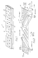
- Figure 1 is a schematic representation of a tag in accordance with the present invention;
- Figure 2 is a schematic representation of a magnetically structured component for use in the tag illustrated in Figure 1 and showing a preferred orientation of the magnetic particles;
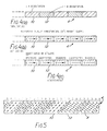
- Figures 3a to 3c show schematic plan views of the magnetically structured component in activated and deactivated states and having the magnetic particles orientated at 0o and 90o to the longitudinal axis of the component;
- Figures 4a to 4c show schematic plan views of the magnetically structured component in activated and deactivated states and having the magnetic particles orientated at ± 45o to the longitudinal axis of the component; and
- Figure 5 is a schematic representation of the magnetically structured component with the magnetic particles configured to define an interpretable code.
- Referring to Figure 1, a tag 2 comprises a magnetically structured
component 4 and an element 6 of magnetically soft material. Thecomponent 4, which preferably is in the form of a strip, is arranged in sufficiently close proximity to the element 6 to permit thecomponent 4, when magnetised, to create in the magnetically soft element 6 a pole pattern sufficient to inhibit generation of the aforementioned harmonies when the tag 2 is subjected to an interrogating field. As shown in Figure 1, thecomponent 4 is arranged to overlie the magnetically soft element 6. However, the tag 2 may equally be fabricated with the element 6 overlying thestructured component 4. - The magnetically structured
component 4 comprisesmagnetic particles 8 dispersed in a binder and orientated into particular directions inrespective regions compoent 4. - The method of manufacturing the
component 4 will not be described in the context of this application as it will be assumed to be known to those skilled in this art. - In the embodiment shown in Figure 3 the tag 2, when activated, has the
magnetic particles 8 orientated at 0o and 90o with respect to the longitudinal axis of thecomponent 4 and also, therefore, of the tag 2 in which thecomponent 4 is embodied. In this activated condition, no pole pattern is induced in the element 6 and hence, the element 6 may be sensed when subjected to an interrogating field of, for example, an electronic article surveillance system. When thecomponent 4 is magnetised, however, such as by a single swipe with a magnet along the longitudinal axis of the component, the magnetic particles having 0o orientations with respect to this axis are aligned to form a pole pattern within the component which, in view of the proximity to the element 6, creates a pole pattern within the element 6, as shown in Figure 3b. In this condition the tag 2 is deactivated as the magnetically soft element 6 cannot be detected by the interrogating field. The tag 2 can be reactivated readily by subjecting thecomponent 4 to an a.c. magnetic field, thereby negating the pole pattern in thecomponent 4, and hence also the pole pattern in the element 6, as shown in Figure 3c, once again enabling the element 6 to be detected by the interrogating field. - It is particularly advantageous to arrange for the
magnetic particles 8 in theselected regions component 4 to be orientated in a direction other than longitudinally of the strip. For example, themagnetic particles 8 may be orientated at 45o to the longitudinal axis, as fabricated, shown in Figure 4a. In this embodiment, the tag 2 is activated by a magnetic swipe along the longitudinal axis of the magnetically structuredcomponent 4, causing a pole pattern in thecomponent 4 as shown in Figure 4b and enabling the element 6 to be detected by an interrogating field. - The tag 2 may be deactivated by "developing" the
component 4 by means of a specially constructed deactivator, designed to be swiped along the longitudinal axis of the strip but to generate a developing magnetic field at an angle corresponding to the angle of orientation of themagnetic particles 8 in theregions - This magnetic swipe causes a reversal of a selection of the magnetic pole patterns in
regions component 4 as shown in Figure 4c. This pole pattern, having like magnetic poles adjacent to each other, induces a pole pattern in the magnetically soft element 6 sufficient to prevent detection of the tag when subjected to an interrogating field. This deactivation of the tag by an appropriately aligned magnetic field renders deactivation simple for a check out operator, but not for the would-be thief who, even if aware of the need for an off-set between the developing field and the direction of swipe would not be aware of the correct angle, which could be changed for different stores and/or batches of product. - The magnetically structured
component 4 can be used to contain coded information if desired, as shown in Figure 5 and, if the coding is matched to various products, or product categories, it is possible for product inventory to be monitored by providing suitable detection and analysis circuitry at the de-activation point and linking such circuitry to the store's central computer. - In any of the above magnetic particle configurations the tag can, of course, be re-activated by de-magnetising the magnetically structured component.
- It has been determined that the thickness required for the magnetically structured component to produce an average longitudinal de-activation field of 10 Oe and on the basis of the component being in strip-like form of width 8mm and with alternate regions of length 2mm being oriented in a chosen direction, with intervening regions either being not orientated or orientated perpendicularly to the first-mentioned regions, is 30-35 microns. This thickness is also dependent on using a magnetically soft element 6 in strip-like form, of about the same width as the
structured component 4. For an element of magnetically soft material 0.026mm thick, 1mm wide and 60mm long, the required thickness of the magnetically structuredcomponent 4 would be approximately 125 microns. - Although the present invention has been described with respect to specific embodiments, it should be realised that modifications may be effected within the scope of the invention. For example, magnetic particle orientations at 0o and 90o or ± 45o have been described. However, magnetic particle orientations at other angles may equally be adopted, although it is preferable to maintain an angle in the region of 90o between the orientation of the particles in the respective elements. Furthermore, the magnetic particles are shown in the embodiments as lying flat within the magnetically structured component. It should be realised, however, that the magnetic axes of the magnetic particles, by suitable known fabrication techniques, can be arranged to stand in an upright condition, either at an angle of about 90o or at an inclined angle, within the magnetically structured component and the present invention is intended to cover also tags incorporating such upright magnetic particle configurations.
Claims (7)
Priority Applications (1)
| Application Number | Priority Date | Filing Date | Title |
|---|---|---|---|
| AT89307582T ATE101736T1 (en) | 1988-07-27 | 1989-07-26 | ELECTROMAGNETIC IDENTIFICATION SYSTEM. |
Applications Claiming Priority (2)
| Application Number | Priority Date | Filing Date | Title |
|---|---|---|---|
| GB8817855 | 1988-07-27 | ||
| GB888817855A GB8817855D0 (en) | 1988-07-27 | 1988-07-27 | Electromagnetic identification system |
Publications (3)
| Publication Number | Publication Date |
|---|---|
| EP0353040A2 true EP0353040A2 (en) | 1990-01-31 |
| EP0353040A3 EP0353040A3 (en) | 1990-05-30 |
| EP0353040B1 EP0353040B1 (en) | 1994-02-16 |
Family
ID=10641180
Family Applications (1)
| Application Number | Title | Priority Date | Filing Date |
|---|---|---|---|
| EP89307582A Expired - Lifetime EP0353040B1 (en) | 1988-07-27 | 1989-07-26 | Electromagnetic identification system |
Country Status (6)
| Country | Link |
|---|---|
| US (1) | US4935724A (en) |
| EP (1) | EP0353040B1 (en) |
| AT (1) | ATE101736T1 (en) |
| CA (1) | CA1301881C (en) |
| DE (1) | DE68913094T2 (en) |
| GB (1) | GB8817855D0 (en) |
Cited By (9)
| Publication number | Priority date | Publication date | Assignee | Title |
|---|---|---|---|---|
| EP0426293A1 (en) * | 1989-10-13 | 1991-05-08 | THORN EMI plc | Improvements in or relating to financial transaction cards |
| EP0459722A1 (en) * | 1990-06-01 | 1991-12-04 | Minnesota Mining And Manufacturing Company | Multi-layer thin-film EAS marker |
| GB2313982A (en) * | 1996-06-07 | 1997-12-10 | Ibm | Magnetic anti-theft and identification tag |
| WO1998013708A1 (en) * | 1996-09-27 | 1998-04-02 | Flying Null Limited | Multi-layer magnetic tag |
| GB2322049A (en) * | 1995-04-04 | 1998-08-12 | Flying Null Ltd | Magnetic Tags |
| EP1016096A2 (en) * | 1997-02-14 | 2000-07-05 | Sensormatic Electronics Corporation | Active element for magnetomechanical eas marker incorporating particles of bias material |
| EP1054343A1 (en) * | 1999-05-19 | 2000-11-22 | Arjo Wiggins S.A. | Substrate comprising a magnetic marking, method of production of that substrate and device utilizing it |
| GB2386192A (en) * | 2002-01-08 | 2003-09-10 | Flying Null Ltd | Magnetic indicator |
| WO2010067071A3 (en) * | 2008-12-11 | 2010-09-23 | Nicholas Charles Davies | Security tag deactivator |
Families Citing this family (15)
| Publication number | Priority date | Publication date | Assignee | Title |
|---|---|---|---|---|
| US5017907A (en) * | 1990-01-16 | 1991-05-21 | Pitney Bowes Inc. | Double pulse magnetic markers |
| US5355120A (en) * | 1992-10-09 | 1994-10-11 | Security Tag Systems, Inc. | Frequency-dividing-transponder tag |
| US5480685A (en) * | 1993-10-22 | 1996-01-02 | Tomoegawa Paper Co., Ltd. | Method of making a magnetic recording medium comprising two magnetic layers |
| US5399372A (en) * | 1993-11-08 | 1995-03-21 | Southwall Technologies, Inc. | Method of patterning magnetic members |
| US5664113A (en) * | 1993-12-10 | 1997-09-02 | Motorola, Inc. | Working asset management system and method |
| US5602527A (en) * | 1995-02-23 | 1997-02-11 | Dainippon Ink & Chemicals Incorporated | Magnetic marker for use in identification systems and an indentification system using such magnetic marker |
| US5602528A (en) * | 1995-06-20 | 1997-02-11 | Marian Rubber Products Company, Inc. | Theft detection marker and method |
| US5717382A (en) * | 1996-03-15 | 1998-02-10 | Avery Dennison Corporation | Device for use in detecting the unauthorized removal of an article of commerce from a store or other business establishment |
| US5736929A (en) * | 1996-06-07 | 1998-04-07 | International Business Machines Corporation | System for concealed serialization utilizing a soft magnetic antitheft element |
| GB9619896D0 (en) * | 1996-09-24 | 1996-11-06 | Flying Null Ltd | Improvements in or relating to magnetic sensors |
| DE19642225A1 (en) * | 1996-10-12 | 1998-04-16 | Esselte Meto Int Gmbh | Securing element for electronic article surveillance and method for producing a securing element |
| US6029891A (en) * | 1997-07-29 | 2000-02-29 | Sensor Research & Development | Magnetic pattern verification system |
| US5920262A (en) * | 1998-06-19 | 1999-07-06 | Sensormatic Electronics Corporation | Omnidirectional deactivator for magnetic labels or tags of EAS systems |
| US7493391B2 (en) * | 2001-02-12 | 2009-02-17 | International Business Machines Corporation | System for automated session resource clean-up by determining whether server resources have been held by client longer than preset thresholds |
| DE102021116855B3 (en) | 2021-06-30 | 2022-04-21 | Sick Ag | Magnetic tagging device for attachment to an object and magnetic identification device |
Citations (7)
| Publication number | Priority date | Publication date | Assignee | Title |
|---|---|---|---|---|
| US4023204A (en) * | 1974-10-16 | 1977-05-10 | Emi Limited | Magnetic recording |
| US4081132A (en) * | 1973-10-23 | 1978-03-28 | E M I Limited | Credit cards and other security documents |
| DE2752895A1 (en) * | 1976-12-06 | 1978-06-08 | Emi Ltd | METHOD FOR PRODUCING A MATERIAL LAYER, THE SURFACE OF WHICH HAS A SCANABLE PATTERN, AS WELL AS A SECURITY DOCUMENT SYSTEM |
| US4104513A (en) * | 1974-10-16 | 1978-08-01 | E M I Limited | Magnetic recording |
| EP0024800A1 (en) * | 1979-08-04 | 1981-03-11 | EMI Limited | Security document and system |
| GB1605042A (en) * | 1978-05-30 | 1981-12-16 | Emi Ltd | Secure information storage |
| EP0150498A2 (en) * | 1984-01-14 | 1985-08-07 | Bayer Ag | Perpendicular Magnetic Recording Medium |
Family Cites Families (3)
| Publication number | Priority date | Publication date | Assignee | Title |
|---|---|---|---|---|
| US4568921A (en) * | 1984-07-13 | 1986-02-04 | Knogo Corporation | Theft detection apparatus and target and method of making same |
| US4752758A (en) * | 1986-07-21 | 1988-06-21 | Minnesota Mining And Manufacturing Company | Demagnetization apparatus for magnetic markers used with article surveilliance systems |
| US4857891A (en) * | 1988-04-29 | 1989-08-15 | Minnesota Mining And Manufacturing Company | Random-filament, multi-directionally responsive marker for use in electronic article surveillance systems |
-
1988
- 1988-07-27 GB GB888817855A patent/GB8817855D0/en active Pending
-
1989
- 1989-07-26 DE DE68913094T patent/DE68913094T2/en not_active Expired - Fee Related
- 1989-07-26 AT AT89307582T patent/ATE101736T1/en not_active IP Right Cessation
- 1989-07-26 EP EP89307582A patent/EP0353040B1/en not_active Expired - Lifetime
- 1989-07-27 CA CA000606784A patent/CA1301881C/en not_active Expired - Lifetime
- 1989-07-27 US US07/385,861 patent/US4935724A/en not_active Expired - Lifetime
Patent Citations (7)
| Publication number | Priority date | Publication date | Assignee | Title |
|---|---|---|---|---|
| US4081132A (en) * | 1973-10-23 | 1978-03-28 | E M I Limited | Credit cards and other security documents |
| US4023204A (en) * | 1974-10-16 | 1977-05-10 | Emi Limited | Magnetic recording |
| US4104513A (en) * | 1974-10-16 | 1978-08-01 | E M I Limited | Magnetic recording |
| DE2752895A1 (en) * | 1976-12-06 | 1978-06-08 | Emi Ltd | METHOD FOR PRODUCING A MATERIAL LAYER, THE SURFACE OF WHICH HAS A SCANABLE PATTERN, AS WELL AS A SECURITY DOCUMENT SYSTEM |
| GB1605042A (en) * | 1978-05-30 | 1981-12-16 | Emi Ltd | Secure information storage |
| EP0024800A1 (en) * | 1979-08-04 | 1981-03-11 | EMI Limited | Security document and system |
| EP0150498A2 (en) * | 1984-01-14 | 1985-08-07 | Bayer Ag | Perpendicular Magnetic Recording Medium |
Cited By (17)
| Publication number | Priority date | Publication date | Assignee | Title |
|---|---|---|---|---|
| US5166501A (en) * | 1989-10-13 | 1992-11-24 | Thorn Emi Plc | Financial transaction cards having tagging element capable of deactivation by application of personalizing data |
| EP0426293A1 (en) * | 1989-10-13 | 1991-05-08 | THORN EMI plc | Improvements in or relating to financial transaction cards |
| EP0459722A1 (en) * | 1990-06-01 | 1991-12-04 | Minnesota Mining And Manufacturing Company | Multi-layer thin-film EAS marker |
| GB2322769B (en) * | 1995-04-04 | 1999-11-10 | Flying Null Ltd | Magnetic coding of articles |
| GB2322049A (en) * | 1995-04-04 | 1998-08-12 | Flying Null Ltd | Magnetic Tags |
| GB2322769A (en) * | 1995-04-04 | 1998-09-02 | Flying Null Ltd | Magnetic Coding of Articles |
| GB2322049B (en) * | 1995-04-04 | 1999-11-10 | Flying Null Ltd | Magnetic markers or tags |
| GB2313982A (en) * | 1996-06-07 | 1997-12-10 | Ibm | Magnetic anti-theft and identification tag |
| WO1998013708A1 (en) * | 1996-09-27 | 1998-04-02 | Flying Null Limited | Multi-layer magnetic tag |
| AU717142B2 (en) * | 1996-09-27 | 2000-03-16 | Flying Null Limited | Magnetic tags |
| EP1016096A2 (en) * | 1997-02-14 | 2000-07-05 | Sensormatic Electronics Corporation | Active element for magnetomechanical eas marker incorporating particles of bias material |
| EP1016096A4 (en) * | 1997-02-14 | 2002-05-22 | Sensormatic Electronics Corp | Active element for magnetomechanical eas marker incorporating particles of bias material |
| EP1054343A1 (en) * | 1999-05-19 | 2000-11-22 | Arjo Wiggins S.A. | Substrate comprising a magnetic marking, method of production of that substrate and device utilizing it |
| FR2793886A1 (en) * | 1999-05-19 | 2000-11-24 | Arjo Wiggins Sa | SUBSTRATE HAVING MAGNETIC MARKING, METHOD FOR MANUFACTURING SAID SUBSTRATE, AND DEVICE USING THE SAME |
| GB2386192A (en) * | 2002-01-08 | 2003-09-10 | Flying Null Ltd | Magnetic indicator |
| GB2386192B (en) * | 2002-01-08 | 2005-10-12 | Flying Null Ltd | Magnetic indicator |
| WO2010067071A3 (en) * | 2008-12-11 | 2010-09-23 | Nicholas Charles Davies | Security tag deactivator |
Also Published As
| Publication number | Publication date |
|---|---|
| EP0353040A3 (en) | 1990-05-30 |
| GB8817855D0 (en) | 1988-09-01 |
| ATE101736T1 (en) | 1994-03-15 |
| EP0353040B1 (en) | 1994-02-16 |
| DE68913094D1 (en) | 1994-03-24 |
| CA1301881C (en) | 1992-05-26 |
| US4935724A (en) | 1990-06-19 |
| DE68913094T2 (en) | 1994-08-25 |
Similar Documents
| Publication | Publication Date | Title |
|---|---|---|
| US4935724A (en) | EAS tag with magnetically structured control element | |
| US6774782B2 (en) | Radio frequency personnel alerting security system and method | |
| US5729201A (en) | Identification tags using amorphous wire | |
| CA2297927C (en) | Electronic article security system for interrogating rfid tags and virtually deactivating and reactivating tags | |
| US5739754A (en) | Circuit antitheft and disabling mechanism | |
| Singh et al. | Application of RFID technology in libraries | |
| CA2372756A1 (en) | Self-checkout/self-check-in rfid and electronic article surveillance system | |
| CA1294017C (en) | Deactivatable coded marker and magnetic article surveillance system | |
| CA1295030C (en) | Antipilferage systems | |
| CA1232647A (en) | Magnetic article surveillance system, method and coded marker | |
| US6778087B2 (en) | Dual axis magnetic field EAS device | |
| AU2002307232A1 (en) | Dual axis magnetic field device for changing status of EAS marker | |
| AU751112B2 (en) | Deactivation element configuration for microwave-magnetic eas marker | |
| US5353010A (en) | Device and a method for detecting a magnetizable marker element | |
| US7015790B1 (en) | Intelligent antitheft method and system combining magnetic tags and smart cards | |
| US6690279B1 (en) | Security element for the electronic surveillance of articles | |
| Chatterjee et al. | Evaluation of using RFID passive tags for monitoring product location/ownership | |
| GB2322769A (en) | Magnetic Coding of Articles | |
| US7532123B2 (en) | Magnetic tagging | |
| Trontelj | Intelligent system for decoupling multiple RFID tags | |
| AU1759700A (en) | Magnetic coding of articles |
Legal Events
| Date | Code | Title | Description |
|---|---|---|---|
| PUAI | Public reference made under article 153(3) epc to a published international application that has entered the european phase |
Free format text: ORIGINAL CODE: 0009012 |
|
| AK | Designated contracting states |
Kind code of ref document: A2 Designated state(s): AT BE CH DE ES FR GB GR IT LI LU NL SE |
|
| PUAL | Search report despatched |
Free format text: ORIGINAL CODE: 0009013 |
|
| AK | Designated contracting states |
Kind code of ref document: A3 Designated state(s): AT BE CH DE ES FR GB GR IT LI LU NL SE |
|
| 17P | Request for examination filed |
Effective date: 19900620 |
|
| 17Q | First examination report despatched |
Effective date: 19921218 |
|
| GRAA | (expected) grant |
Free format text: ORIGINAL CODE: 0009210 |
|
| AK | Designated contracting states |
Kind code of ref document: B1 Designated state(s): AT BE CH DE ES FR GB GR IT LI LU NL SE |
|
| PG25 | Lapsed in a contracting state [announced via postgrant information from national office to epo] |
Ref country code: IT Free format text: LAPSE BECAUSE OF FAILURE TO SUBMIT A TRANSLATION OF THE DESCRIPTION OR TO PAY THE FEE WITHIN THE PRESCRIBED TIME-LIMIT;WARNING: LAPSES OF ITALIAN PATENTS WITH EFFECTIVE DATE BEFORE 2007 MAY HAVE OCCURRED AT ANY TIME BEFORE 2007. THE CORRECT EFFECTIVE DATE MAY BE DIFFERENT FROM THE ONE RECORDED. Effective date: 19940216 Ref country code: ES Free format text: THE PATENT HAS BEEN ANNULLED BY A DECISION OF A NATIONAL AUTHORITY Effective date: 19940216 Ref country code: AT Effective date: 19940216 Ref country code: GR Free format text: LAPSE BECAUSE OF FAILURE TO SUBMIT A TRANSLATION OF THE DESCRIPTION OR TO PAY THE FEE WITHIN THE PRESCRIBED TIME-LIMIT Effective date: 19940216 Ref country code: SE Effective date: 19940216 Ref country code: BE Effective date: 19940216 |
|
| REF | Corresponds to: |
Ref document number: 101736 Country of ref document: AT Date of ref document: 19940315 Kind code of ref document: T |
|
| REF | Corresponds to: |
Ref document number: 68913094 Country of ref document: DE Date of ref document: 19940324 |
|
| ET | Fr: translation filed | ||
| PG25 | Lapsed in a contracting state [announced via postgrant information from national office to epo] |
Ref country code: LU Free format text: LAPSE BECAUSE OF NON-PAYMENT OF DUE FEES Effective date: 19940731 |
|
| PLBE | No opposition filed within time limit |
Free format text: ORIGINAL CODE: 0009261 |
|
| STAA | Information on the status of an ep patent application or granted ep patent |
Free format text: STATUS: NO OPPOSITION FILED WITHIN TIME LIMIT |
|
| 26N | No opposition filed | ||
| REG | Reference to a national code |
Ref country code: GB Ref legal event code: 732E |
|
| NLS | Nl: assignments of ep-patents |
Owner name: CENTRAL RESEARCH LABORATORIES LIMITED |
|
| REG | Reference to a national code |
Ref country code: FR Ref legal event code: TP Free format text: CORRECTION |
|
| PGFP | Annual fee paid to national office [announced via postgrant information from national office to epo] |
Ref country code: FR Payment date: 20000628 Year of fee payment: 12 |
|
| PGFP | Annual fee paid to national office [announced via postgrant information from national office to epo] |
Ref country code: NL Payment date: 20000731 Year of fee payment: 12 |
|
| PGFP | Annual fee paid to national office [announced via postgrant information from national office to epo] |
Ref country code: CH Payment date: 20000808 Year of fee payment: 12 |
|
| PGFP | Annual fee paid to national office [announced via postgrant information from national office to epo] |
Ref country code: DE Payment date: 20000928 Year of fee payment: 12 |
|
| PG25 | Lapsed in a contracting state [announced via postgrant information from national office to epo] |
Ref country code: LI Free format text: LAPSE BECAUSE OF NON-PAYMENT OF DUE FEES Effective date: 20010731 Ref country code: CH Free format text: LAPSE BECAUSE OF NON-PAYMENT OF DUE FEES Effective date: 20010731 |
|
| REG | Reference to a national code |
Ref country code: GB Ref legal event code: IF02 |
|
| PG25 | Lapsed in a contracting state [announced via postgrant information from national office to epo] |
Ref country code: NL Free format text: LAPSE BECAUSE OF NON-PAYMENT OF DUE FEES Effective date: 20020201 |
|
| REG | Reference to a national code |
Ref country code: CH Ref legal event code: PL |
|
| PG25 | Lapsed in a contracting state [announced via postgrant information from national office to epo] |
Ref country code: FR Free format text: LAPSE BECAUSE OF NON-PAYMENT OF DUE FEES Effective date: 20020329 |
|
| NLV4 | Nl: lapsed or anulled due to non-payment of the annual fee |
Effective date: 20020201 |
|
| PG25 | Lapsed in a contracting state [announced via postgrant information from national office to epo] |
Ref country code: DE Free format text: LAPSE BECAUSE OF NON-PAYMENT OF DUE FEES Effective date: 20020501 |
|
| REG | Reference to a national code |
Ref country code: FR Ref legal event code: ST |
|
| PGFP | Annual fee paid to national office [announced via postgrant information from national office to epo] |
Ref country code: GB Payment date: 20030904 Year of fee payment: 15 |
|
| PG25 | Lapsed in a contracting state [announced via postgrant information from national office to epo] |
Ref country code: GB Free format text: LAPSE BECAUSE OF NON-PAYMENT OF DUE FEES Effective date: 20040726 |
|
| GBPC | Gb: european patent ceased through non-payment of renewal fee |
Effective date: 20040726 |