EP0354130A1 - Method and machine for adding a substance to a liquid, particularly for adding a ferment to wine - Google Patents
Method and machine for adding a substance to a liquid, particularly for adding a ferment to wine Download PDFInfo
- Publication number
- EP0354130A1 EP0354130A1 EP89402219A EP89402219A EP0354130A1 EP 0354130 A1 EP0354130 A1 EP 0354130A1 EP 89402219 A EP89402219 A EP 89402219A EP 89402219 A EP89402219 A EP 89402219A EP 0354130 A1 EP0354130 A1 EP 0354130A1
- Authority
- EP
- European Patent Office
- Prior art keywords
- product
- cavity
- liquid
- flow
- control member
- Prior art date
- Legal status (The legal status is an assumption and is not a legal conclusion. Google has not performed a legal analysis and makes no representation as to the accuracy of the status listed.)
- Withdrawn
Links
Images
Classifications
-
- B—PERFORMING OPERATIONS; TRANSPORTING
- B65—CONVEYING; PACKING; STORING; HANDLING THIN OR FILAMENTARY MATERIAL
- B65B—MACHINES, APPARATUS OR DEVICES FOR, OR METHODS OF, PACKAGING ARTICLES OR MATERIALS; UNPACKING
- B65B3/00—Packaging plastic material, semiliquids, liquids or mixed solids and liquids, in individual containers or receptacles, e.g. bags, sacks, boxes, cartons, cans, or jars
- B65B3/26—Methods or devices for controlling the quantity of the material fed or filled
- B65B3/30—Methods or devices for controlling the quantity of the material fed or filled by volumetric measurement
-
- B—PERFORMING OPERATIONS; TRANSPORTING
- B67—OPENING, CLOSING OR CLEANING BOTTLES, JARS OR SIMILAR CONTAINERS; LIQUID HANDLING
- B67C—CLEANING, FILLING WITH LIQUIDS OR SEMILIQUIDS, OR EMPTYING, OF BOTTLES, JARS, CANS, CASKS, BARRELS, OR SIMILAR CONTAINERS, NOT OTHERWISE PROVIDED FOR; FUNNELS
- B67C3/00—Bottling liquids or semiliquids; Filling jars or cans with liquids or semiliquids using bottling or like apparatus; Filling casks or barrels with liquids or semiliquids
- B67C3/02—Bottling liquids or semiliquids; Filling jars or cans with liquids or semiliquids using bottling or like apparatus
- B67C3/20—Bottling liquids or semiliquids; Filling jars or cans with liquids or semiliquids using bottling or like apparatus with provision for metering the liquids to be introduced, e.g. when adding syrups
- B67C3/208—Bottling liquids or semiliquids; Filling jars or cans with liquids or semiliquids using bottling or like apparatus with provision for metering the liquids to be introduced, e.g. when adding syrups specially adapted for adding small amounts of additional liquids, e.g. syrup
Definitions
- the invention relates to a method and a machine for adding a product to a liquid, in particular for adding ferment to wine.
- the present invention aims to create a means for adding in a determined amount a product in the form of powder, pulp, granules, beads, etc. to a liquid and, in particular, to add a ferment to wine to make sparkling wine.
- the invention relates to a process characterized in that a dose of product is determined to add, this dose is placed on the path of the liquid towards the container and the product is introduced into the container by the flow of the liquid which flows towards the container for its packaging.
- the product to be added is wetted, preferably with the liquid to be conditioned and the dose of wetted product is then determined.
- the dose of product on the path of the liquid flowing to the container is determined.
- the invention also relates to a machine for implementing the method as defined above, this machine being characterized in that it comprises, on the one hand, a body connected to a chamber containing the liquid to be conditioned, this body comprising a cavity connected to a supply pipe for the product to be added, and on the other hand, a sliding control member passing right through the cavity and comprising a liquid flow channel towards a flow orifice, this channel being closed by two valves arranged on either side of the cavity, one to prevent the flow of liquid to the cavity, the other to prevent the flow of the product to be added from the cavity to the flow hole.
- This description will relate, by way of example, to a machine for adding ferment beads to wine bottles.
- the present invention therefore has for its object a method and a machine which make it possible to successively dose determined quantities of ferment balls and to introduce these doses into the wine bottles, without these balls being deteriorated during dosing and transfer. , using the wine to fill the bottles as a means of transfer.
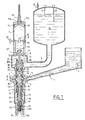
- balls are arranged in bulk, for example in a hopper 1, the lower opening of which opens into a conduit 11 leading to a lateral bore 2 of the body 3 of a withdrawal head.
- This bore 2 leads to a metering cavity 4 which has an annular rim 5, preferably circular, directed towards the lower end of the head, that is to say in the direction of flow of the wine, and the lower edge is located along a plane referenced 6.
- the balls are placed in the hopper with a liquid the quantity of which is sufficient to wet the balls, this liquid being, of course, preferably identical to that which must be bottled.
- This wine acting as a wetting product, carries with it the balls in the duct 11, the bore 2 and in the cavity 4 and this up to the level of the plane 6 constituted by the plane 6 of the opening of the annular rim 5.
- the balls are arranged exactly in the cavity 4 up to level 6 due to an overpressure which is established in this cavity, as will be specified later during the explanation of the operation of the machine.
- the upper part of the body 3 is provided with a cylindrical chamber 7 of determined volume, and containing the exact quantity of wine which must be introduced into a bottle.
- This chamber 7 has at its lower end an opening 71 which puts it in communication via an enclosure 8 and a pipe 9 with a tank 10 containing the wine which it is desired to draw.
- This tank 10 is provided at its upper end with level probes 11 and 12 respectively controlling the stopping of the filling of the tank 10 with wine from a tank, or on the contrary, the supply of this tank.
- the upper end of the tank is brought to atmospheric pressure by a tube 13, this tube possibly being used for the introduction into this tank, of a neutral gas to avoid oxidation of the wine.
- the upper end of the chamber 7 comprises a piston 14 whose hollow rod 141 is mounted by screwing in 142 through the upper wall of the chamber 7.
- This rod 141 is immobilized by a 143 nut.
- the screwing in one direction or the other of the rod 141 makes it possible to adjust the position of the piston 14 in the chamber 7 in order to determine with precision its volume and, therefore, the volume of liquid which will be introduced into a bottle.
- a sliding control member 15 which comprises: - An axial channel 16 known as the venting of the bottle during its filling and which opens laterally in 161 on this body 15, as well as in 162 at its lower end; - A bulge 17 located substantially at the height of the cavity 4 and whose lower end at 171 forms a valve seat on which is applied in a sealed manner a ring 18 pushed by a helical spring 19; an annular passage 20 for the flow of wine and the balls, which is normally closed at its upper end, at the height of the valve seat 171 formed between the bulge 17 and the ring 18.
- this flow channel 20 is closed by a valve 211, intended to prevent drops of wine from flowing from the head outside the periods of filling the bottles, this valve being formed at the lower end of a sleeve 22 produced in several pieces.
- This valve 211 comes to bear, under the action of a helical spring 23, against the flared end, forming a valve seat, from the lower end of the axial channel 16; -
- An upper extension 38 provided with a hole 381.
- This extension is produced at the upper end of the bulge 17 and delimits a chamber 24 communicating with the cavity 4 of the body 3 by a circular arrangement of perforations 25 formed between the head 17 and the extension 38; - A valve 26 which closes the upper end of the chamber 24 of the extension 38 this valve being held in the closed position by a spring 27 working in compression.
- This valve 26 comprises a rod 28 which passes through the bore 381 and which is provided, at its upper end, with a head 29 housed inside the chamber 7.
- This head is capable of being actuated by a cam 30 mounted on an axis 31 comprising, moreover, a control roller 32 disposed outside the reservoir 7.
- the upper end of the body 15, constituted by the extension 23, forms at 33 a valve capable of being applied to a valve seat 34 formed at the lower end of the opening 7 of the chamber 7.
- Seals generally designated by the reference 35 are provided to seal between the various moving parts.
- the ring 18 sliding in leaktight manner on the body 15, is provided at its upper end with an annular lip 181.
- the ring 18 and its lip 181 are designed so that, in the low position (see Figures 1 and 2), the lip is located below the plane 6 while, in the high position (see Figures 3, 4 and 5) it comes to be placed above the plane 6 by sealingly applying against the seat 36 formed on the body 3, at the upper end of the cavity 4.
- the lip 181 is thin so as not to risk crushing balls when it is applied against the seat 36 and its diameter is less than that of the annular flange 5, so that during the axial and simultaneous vertical displacement of the ring 18 and the bulge 17 of the control member 15, these two pieces cross the bed of beads and wine which extends to the level of plane 6 by lifting a determined quantity of these beads.
- a determined dose of balls 37 is formed in the annular housing delimited by, on the one hand, the ring 18 and its lip 181, on the other hand, the bulge 17.
- the first stage corresponds to the filling of the chamber 7 with the dose of wine which must fill the bottle and to the first stage of formation of a dose of beads in the cavity 4.
- the wine fills the chamber 7 by the principle of communicating vessels, since the reservoir 10 and this chamber 7 are in communication with the open air, respectively by the tube 13 and by the hollow rod 141 of the piston 14.
- the wine therefore completely fills the chamber 7 as well as partially the hollow rod 141, since the feelers 11 and 12 determine, in the tank 10, a level of liquid which is located at the height of this hollow rod 141.
- the balls wetted by the wine flow in the pipe 1 to the cavity 4 where a bed of balls piled up on top of each other is formed, their level being however limited to that of plane 6 determined by the lower edge of the circular lip 5.
- the fourth operating stage is shown in FIG. 4 and corresponds to the continuation of the relative axial movement of the bottle and the head, resulting in the lifting of the control member 15 in the body 3.
- the last operating stage of the head is represented in FIG. 5 and corresponds to the flow of wine from chamber 7 into the bottle with simultaneous entrainment of the dose of balls 37, of which only a small quantity, or even none of between them, has not yet reached the bottle.
- This flow is obtained by actuation of the valve 26 from the cam 30, itself actuated, outside the head, by the roller 32.
- the machine will include a large number of heads similar to that described, arranged circularly on the periphery of a rotating barrel and, in this case, the rollers 32 will be controlled by a fixed cam, in order to produce the opening of the valve 26 in a determined angular position of the barrel.
- the roller 32 controls the lifting of the valve 26 which again comes to apply in a sealed manner on the seat 25. Also, the full bottle and the head move in a reverse relative axial movement, as shown successively in FIGS. 4, 3, 2 and 1, so that the volume of air contained in the enclosure 24 and cavity 4 tends to compress since, during this downward movement of the body 15, this volume of air is limited in its upper zone by the closed valve 36 and in its lower zone by the fixed and sealed surface formed by the bed of wet balls of wine placed at level 6 formed by the lower end of the annular lip 5.
- this machine makes it possible to transfer the balls to the dosing cavity, using the wine as a transfer means, makes it possible to carry out the dosing of a determined quantity of balls by using the wine as a means of obturation at the level of the plan 6 and using the wine as a means of transferring the beads from the dosing cavity and towards the bottle, since the exact dose of beads is placed in the flow of wine flowing to the bottle.
- These beads always accompanied by wine in the transfer and dosing operations, are therefore dosed and brought into the bottle without having been damaged.
- the invention has been described above in its application to the manufacture of a wine sparkling by addition of a ferment, the invention can be applied in general to the addition of a product of any kind, to a liquid, during the packaging of this liquid.
Abstract
Description
L'invention concerne un procédé et une machine pour ajouter un produit à un liquide, notamment pour l'ajout de ferment dans le vin.The invention relates to a method and a machine for adding a product to a liquid, in particular for adding ferment to wine.
Il existe de nombreux cas dans lesquels il convient d'ajouter un additif à un liquide, additif qui peut se présenter sous des formes très diverses telles que poudre, pulpe notamment de fruits, granulés, etc. C'est ainsi que pour la fermentation du vin, on a imaginé de mettre le ferment sous forme de micro-capsules ou billes enrobées d'un produit du genre gélatine.There are many cases in which an additive should be added to a liquid, an additive which can be in very diverse forms such as powder, pulp, in particular of fruit, granules, etc. Thus, for the fermentation of wine, it was imagined to put the ferment in the form of micro-capsules or beads coated with a product of the gelatin type.
Cependant, le problème principal posé par l'emploi de ces micro-capsules ou "billes" de ferment, réside dans le fait qu'elles sont relativement fragiles et qu'elles ne doivent pas être blessées lors de leur introduction dans les bouteilles pour ne pas troubler le liquide.However, the main problem posed by the use of these micro-capsules or "beads" of ferment, resides in the fact that they are relatively fragile and that they must not be injured during their introduction into the bottles so as not to not disturb the liquid.
La présente invention a pour but de créer un moyen permettant d'additionner en quantité déterminée un produit en forme de poudre, pulpe, granulés, billes, etc. à un liquide et, en particulier, d'ajouter un ferment à du vin pour fabriquer du vin mousseux.The present invention aims to create a means for adding in a determined amount a product in the form of powder, pulp, granules, beads, etc. to a liquid and, in particular, to add a ferment to wine to make sparkling wine.
A cet effet, l'invention concerne un procédé caractérisé en ce qu'on détermine une dose de produit à ajouter, on place cette dose sur le trajet du liquide vers le récipient et on introduit le produit dans le récipient par le flux du liquide qui s'écoule vers le récipient pour son conditionnement.To this end, the invention relates to a process characterized in that a dose of product is determined to add, this dose is placed on the path of the liquid towards the container and the product is introduced into the container by the flow of the liquid which flows towards the container for its packaging.
Suivant une autre caractéristique de l'invention, on mouille le produit à ajouter, de préférence par le liquide à conditionner et on détermine ensuite la dose de produit mouillé.According to another characteristic of the invention, the product to be added is wetted, preferably with the liquid to be conditioned and the dose of wetted product is then determined.
Suivant une autre caractéristique de l'invention, on détermine la dose de produit sur le trajet du liquide s'écoulant vers le récipient.According to another characteristic of the invention, the dose of product on the path of the liquid flowing to the container is determined.
L'invention concerne également une machine pour la mise en oeuvre du procédé tel que défini ci-dessus, cette machine étant caractérisée en ce qu'elle comprend, d'une part, un corps relié à une chambre contenant le liquide à conditionner, ce corps comportant une cavité reliée à une canalisation d'alimentation en produit à ajouter, et d'autre part, un organe de commande coulissant traversant de part en part la cavité et comportant un canal d'écoulement du liquide vers un orifice d'écoulement, ce canal étant obturé par deux clapets disposés de part et d'autre de la cavité, l'un pour interdire l'écoulement du liquide vers la cavité, l'autre pour interdire l'écoulement du produit à ajouter de la cavité vers l'orifice d'écoulement.The invention also relates to a machine for implementing the method as defined above, this machine being characterized in that it comprises, on the one hand, a body connected to a chamber containing the liquid to be conditioned, this body comprising a cavity connected to a supply pipe for the product to be added, and on the other hand, a sliding control member passing right through the cavity and comprising a liquid flow channel towards a flow orifice, this channel being closed by two valves arranged on either side of the cavity, one to prevent the flow of liquid to the cavity, the other to prevent the flow of the product to be added from the cavity to the flow hole.
L'invention est représentée à titre d'exemple non limitatif sur les dessins ci-joints dans lesquels :
- - la figure 1 est une vue en coupe axiale d'un exemple de réalisation d'une tête de soutirage conforme à l'invention, cette tête étant représentée au stade initial de détermination de la dose de produit devant être introduite dans une bouteille ;
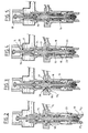
- - les figures 2, 3, 4 et 5 sont des vues en coupe partielle représentant les stades successifs du fonctionnement de la tête, à savoir :
- - figure 2 : ouverture de l'obturateur inférieur,
- - figure 3 : détermination de la dose de billes,
- - figure 4 : libération de la dose de billes,
- - figure 5 : remplissage d'une bouteille par le liquide et évacuation simultanée de la dose de billes vers la bouteille.
- - Figure 1 is an axial sectional view of an embodiment of a filling head according to the invention, this head being shown at the initial stage of determining the dose of product to be introduced into a bottle;
- - Figures 2, 3, 4 and 5 are views in partial section representing the successive stages of the functioning of the head, namely:
- - Figure 2: opening of the lower shutter,
- - Figure 3: determination of the dose of beads,
- - Figure 4: release of the dose of beads,
- - Figure 5: filling of a bottle with the liquid and simultaneous evacuation of the dose of beads to the bottle.
La présente description se rapportera, à titre d'exemple, à une machine pour l'ajout de billes de ferment dans des bouteilles de vin.This description will relate, by way of example, to a machine for adding ferment beads to wine bottles.
La présente invention a en conséquence pour but un procédé et une machine qui permettent de doser successivement des quantités déterminées de billes de ferment et d'introduire ces doses dans les bouteilles de vin, sans que ces billes soient détériorées au cours du dosage et du transfert, en utilisant comme moyen de transfert le vin devant remplir les bouteilles.The present invention therefore has for its object a method and a machine which make it possible to successively dose determined quantities of ferment balls and to introduce these doses into the wine bottles, without these balls being deteriorated during dosing and transfer. , using the wine to fill the bottles as a means of transfer.
Suivant l'invention, il a également été prévu de mouiller les billes préalablement à toute manipulation, afin de faciliter leur mobilité les unes par rapport aux autres, ainsi que par rapport aux différentes parois des conduits dans lesquels elles se déplacent, ce liquide de mouillage agissant ainsi pour favoriser leur dosage.According to the invention, provision has also been made to wet the balls before any manipulation, in order to facilitate their mobility with respect to each other, as well as with respect to the different walls of the conduits in which they move, this wetting liquid thus acting to favor their dosage.
Ces billes sont disposées en vrac, par exemple dans une trémie 1, dont l'ouverture inférieure débouche dans un conduit 1₁ aboutissant à un perçage latéral 2 du corps 3 d'une tête de soutirage. Ce perçage 2 aboutit à une cavité de dosage 4 qui présente un rebord annulaire 5, de préférence circulaire, dirigé vers l'extrémité inférieure de la tête, c'est-à-dire dans le sens d'écoulement du vin, et dont le bord inférieur est situé suivant un plan référencé 6.These balls are arranged in bulk, for example in a hopper 1, the lower opening of which opens into a
Les billes sont disposées dans la trémie avec un liquide dont la quantité est suffisante pour mouiller les billes, ce liquide étant, bien entendu, de préférence identique à celui que l'on doit mettre en bouteille. Ce vin, agissant comme produit mouillant, entraîne avec lui les billes dans le conduit 1₁, le perçage 2 et dans la cavité 4 et cela jusqu'au niveau du plan 6 constitué par le plan 6 de l'ouverture du rebord annulaire 5.The balls are placed in the hopper with a liquid the quantity of which is sufficient to wet the balls, this liquid being, of course, preferably identical to that which must be bottled. This wine, acting as a wetting product, carries with it the balls in the
Les billes se disposent exactement dans la cavité 4 jusqu'au niveau 6 en raison d'une surpression qui s'établit dans cette cavité, comme cela sera précisé ultérieurement lors de l'explication du fonctionnement de la machine.The balls are arranged exactly in the
La partie supérieure du corps 3 est pourvue d'une chambre cylindrique 7 de volume déterminé, et contenant la quantité exacte de vin qui doit être introduite dans une bouteille. Cette chambre 7 comporte à son extrémité inférieure une ouverture 7₁ qui la met en communication par l'intermédiaire d'une enceinte 8 et d'une canalisation 9 avec un réservoir 10 contenant le vin que l'on désire soutirer. Ce réservoir 10 est pourvu à son extrémité supérieure de sondes de niveau 11 et 12 commandant respectivement l'arrêt du remplissage du réservoir 10 par le vin provenant d'une cuve, ou au contraire, l'alimentation de ce réservoir. L'extrémité supérieure du réservoir est mise à la pression atmosphérique par une tubulure 13, cette tubulure pouvant éventuellement servir à l'introduction dans ce réservoir, d'un gaz neutre pour éviter l'oxydation du vin.The upper part of the
L'extrémité supérieure de la chambre 7 comporte un piston 14 dont la tige creuse 14₁ est montée par vissage en 14₂ au travers de la paroi supérieure de la chambre 7. Cette tige 14₁ est immobilisée par un écrou 14₃. Le vissage dans un sens ou dans l'autre de la tige 14₁ permet de régler la position du piston 14 dans la chambre 7 afin de déterminer avec précision son volume et, donc, le volume de liquide qui sera introduit dans une bouteille.The upper end of the
A l'intérieur du corps 3, est disposé un organe de commande coulissant 15 qui comporte :
- un canal axial 16 dit de mise à l'air libre de la bouteille au cours de son remplissage et qui débouche latéralement en 16₁ sur ce corps 15, ainsi qu'en 16₂ à son extrémité inférieure ;
- un renflement 17 situé sensiblement à hauteur de la cavité 4 et dont l'extrémité inférieure forme en 17₁ un siège de clapet sur lequel vient s'appliquer de manière étanche une bague 18 poussée par un ressort hélicoïdal 19 ;
- un passage annulaire 20 d'écoulement du vin et des billes, qui est normalement obturé à son extrémité supérieure, à hauteur du siège de clapet 17₁ formé entre le renflement 17 et la bague 18. L'extrémité inférieure de ce canal d'écoulement 20 est obturée par un clapet 21₁, destiné à éviter que des gouttes de vin s'écoulent de la tête en dehors des périodes de remplissage des bouteilles, ce clapet étant formé à l'extrémité inférieure d'un manchon 22 réalisé en plusieurs pièces. Ce clapet 21₁ vient en appui, sous l'action d'un ressort hélicoïdal 23, contre l'extrémité évasée, formant siège de clapet, de l'extrémité inférieure du canal axial 16 ;
- un prolongement supérieur 38, pourvu d'un perçage 38₁. Ce prolongement est réalisé à l'extrémité supérieure du renflement 17 et délimite une chambre 24 communiquant avec la cavité 4 du corps 3 par une disposition circulaire de perforations 25 formées entre la tête 17 et le prolongement 38 ;
- un clapet 26 qui obture l'extrémité supérieure de la chambre 24 du prolongement 38 ce clapet étant maintenu en position de fermeture par un ressort 27 travaillant en compression. Ce clapet 26 comporte une tige 28 qui traverse le perçage 38₁ et qui est pourvue, à son extrémité supérieure, d'une tête 29 logée à l'intérieur de la chambre 7. Cette tête est susceptible d'être actionnée par une came 30 montée sur un axe 31 comportant, par ailleurs, un galet de commande 32 disposé à l'extérieur du réservoir 7. L'extrémité supérieure du corps 15, constitué par le prolongement 23, forme en 33 un clapet susceptible de venir s'appliquer sur un siège de clapet 34 formé à l'extrémité inférieure de l'ouverture 7 de la chambre 7.Inside the
- An
- A
an
- An
- A
Des joints d'étanchéité désignés d'une manière générale par la référence 35, sont prévus pour assurer l'étanchéité entre les diverses pièces mobiles.Seals generally designated by the
Par ailleurs, la bague 18 coulissant de manière étanche sur le corps 15, est pourvue à son extrémité supérieure d'une lèvre annulaire 18₁. La bague 18 ainsi que sa lèvre 18₁ sont conçues de façon que, en position basse (voir figures 1 et 2), la lèvre est située en-dessous du plan 6 alors que, en position haute (voir figures 3, 4 et 5) elle vient se placer au-dessus du plan 6 en s'appliquant de manière étanche contre le siège 36 formé sur le corps 3, à l'extrémité supérieure de la cavité 4.Furthermore, the
La lèvre 18₁ est de faible épaisseur afin de ne pas risquer d'écraser des billes lors de son application contre le siège 36 et son diamètre est inférieur à celui du rebord annulaire 5, afin qu'au cours du déplacement vertical axial et simultané de la bague 18 et du renflement 17 de l'organe de commande 15, ces deux pièces traversent le lit de billes et de vin qui s'étend jusqu'au niveau du plan 6 en soulevant une quantité déterminée de ces billes. Ainsi, lorsque la lèvre 18₁ vient s'appliquer contre son siège 36, une dose déterminée de billes 37 (voir figure 3) est formée dans le logement annulaire délimité par, d'une part, la bague 18 et sa lèvre 18₁, d'autre part, le renflement 17.The
Le fonctionnement de ce dispositif est le suivant.The operation of this device is as follows.
Le premier stade (figure 1) correspond au remplissage de la chambre 7 par la dose de vin qui doit remplir la bouteille et à la première étape de formation d'une dose de billes dans la cavité 4.The first stage (FIG. 1) corresponds to the filling of the
Le vin remplit la chambre 7 par le principe des vases communicants, étant donné que le réservoir 10 ainsi que cette chambre 7, sont en communication avec l'air libre, respectivement par la tubulure 13 et par la tige creuse 14₁ du piston 14. Le vin remplit donc totalement la chambre 7 ainsi que partiellement la tige creuse 14₁, étant donné que les palpeurs 11 et 12 déterminent, dans le réservoir 10, un niveau de liquide qui est situé à hauteur de cette tige creuse 14₁. Pendant ce premier stade de fonctionnement de la tête de soutirage, les billes mouillées par le vin s'écoulent dans la canalisation 1 jusqu'à la cavité 4 où il se forme un lit de billes entassées les unes sur les autres, leur niveau étant cependant limité à celui du plan 6 déterminé par le bord inférieur de la lèvre circulaire 5.The wine fills the
Lorsqu'une bouteille vient se placer contre le tampon en matière souple 22₁ du manchon 22, le déplacement relatif axial de la tête et de la bouteille produit le soulèvement du manchon 22 à l'encontre du ressort 23 et éventuellement à l'encontre d'un ressort disposé entre le manchon 22 et le corps 15 (deuxième stade du cycle représenté sur la figure 2). Ce mouvement a pour effet d'ouvrir le clapet 21₁ formé entre l'extrémité 16₂ du passage axial 16 et l'extrémité inférieure de la bague 22. L'ouverture de ce clapet est destinée à rendre possible l'écoulement ultérieur du vin et des billes.When a bottle is placed against the
Au troisième stade du cycle de fonctionnement (voir figure 3), le déplacement axial relatif de la bouteille et de la tête de soutirage se poursuit, si bien que le manchon 22 qui est en position haute par rapport à l'organe de commande 15, soulève maintenant cet organe de commande 15 ainsi que la bague 18 qui est toujours en appui sur le siège 17₁ par le ressort 19. Lors de ce soulèvement, la lèvre 18₁ traverse le lit de billes en entraînant avec elle la dose exacte de billes désirée. Lorsque la lèvre 18₁ vient s'appliquer de manière étanche contre le siège 36, cette dose de billes 37 est parfaitement isolée des billes restantes de la cavité 4.At the third stage of the operating cycle (see FIG. 3), the relative axial movement of the bottle and the withdrawal head continues, so that the
Le quatrième stade de fonctionnement est représenté sur la figure 4 et correspond à la poursuite du déplacement axial relatif de la bouteille et de la tête, se traduisant par le soulèvement de l'organe de commande 15 dans le corps 3.The fourth operating stage is shown in FIG. 4 and corresponds to the continuation of the relative axial movement of the bottle and the head, resulting in the lifting of the
A ce stade, le soulèvement de l'organe de commande se poursuit à l'encontre du ressort 23 en appui sur le corps 3 et à l'encontre du ressort 19 en appui sur la bague 18, elle-même immobilisée par application de sa lèvre 18₁ contre le siège 36. Le renflement 17 de l'organe de commande se soulève alors par rapport à la bague 18, ce qui a pour effet d'ouvrir le clapet 17₁ en autorisant la dose de billes 37 à s'écouler par le passage annulaire 20 et le clapet ouvert à l'extrémité inférieure 21₁ du manchon 22.At this stage, the lifting of the control member continues against the
Le déplacement axial du corps 15 se poursuit jusqu'à ce que le clapet 33 vienne s'appliquer contre le siège 34 formé à l'extrémité inférieure de l'ouverture 7₁ de la chambre 7, ce qui a pour effet de séparer le volume déterminé de vin de la chambre 7 de celui qui se trouve dans l'enceinte 8. A partir de cet instant, le corps 15 est immobilisé et la poursuite du déplacement axial de la tête et de la bouteille se traduit uniquement par la compression du ressort 23, c'est-à-dire par le déplacement du manchon 22.The axial movement of the
Le dernier stade de fonctionnement de la tête est représenté sur la figure 5 et correspond à l'écoulement du vin de la chambre 7 dans la bouteille avec entraînement simultané de la dose de billes 37, dont seulement une petite quantité, voire même aucune d'entre elles, n'a encore atteint la bouteille.The last operating stage of the head is represented in FIG. 5 and corresponds to the flow of wine from
Cet écoulement est obtenu par actionnement du clapet 26 à partir de la came 30, elle-même actionnée, à l'extérieur de la tête, par le galet 32.This flow is obtained by actuation of the
Dans la pratique, la machine comportera un grand nombre de têtes similaires à celle décrite, rangées circulairement à la périphérie d'un barillet tournant et, dans ce cas, les galets 32 seront commandés par une came fixe, afin de produire l'ouverture du clapet 26 dans une position angulaire déterminée du barillet.In practice, the machine will include a large number of heads similar to that described, arranged circularly on the periphery of a rotating barrel and, in this case, the
Lorsque la chambre 7 est vide et que le vin qu'elle contenait, ainsi que les billes de la dose 37, sont disposés dans la bouteille, le galet 32 commande le soulèvement du clapet 26 qui vient à nouveau s'appliquer de manière étanche sur le siège 25. Egalement, la bouteille pleine et la tête se déplacent d'un mouvement axial relatif inverse, comme représenté successivement sur les figures 4, 3, 2 et 1, si bien que le volume d'air contenu dans l'enceinte 24 et la cavité 4 tend à se comprimer puisque, lors de ce mouvement de descente du corps 15, ce volume d'air est limité dans sa zone supérieure par le clapet fermé 36 et dans sa zone inférieure par la surface fixe et étanche constituée par le lit de billes mouillées de vin disposé au niveau 6 formé par l'extrémité inférieure de la lèvre annulaire 5.When the
On notera en effet que l'étanchéité est assurée par le vin qui mouille les billes et qui s'accumule autour des billes dans la cavité 4, qui est plus basse que le réservoir 1, et jusqu'au niveau 6.It will in fact be noted that the seal is ensured by the wine which wets the balls and which accumulates around the balls in the
Lors de la descente du corps 5, le volume d'air de l'enceinte 24 et de la cavité 4 est donc comprimé, ce qui a pour effet de coopérer à la disposition des billes, très exactement suivant le niveau 6. Il s'établit en effet un équilibrage de pression entre les billes contenues dans la canalisation 1 et l'air comprimé de la chambre 24 et de la cavité 4, l'excédent d'air comprimé s'évacuant vers l'extérieur en passant par-dessous la lèvre 5 puis dans la canalisation 1₁ remplie de billes et enfin vers la trémie 1.During the descent of the
On constate donc que cette machine permet de transférer les billes vers la cavité de dosage, en utilisant le vin comme moyen de transfert, permet de réaliser le dosage d'une quantité déterminée de billes en utilisant le vin comme moyen d'obturation au niveau du plan 6 et en utilisant le vin comme moyen de transfert des billes depuis la cavité de dosage et vers la bouteille, puisque la dose exacte de billes est placée dans le flux de vin s'écoulant vers la bouteille. Ces billes, toujours accompagnées de vin dans les opérations de transfert et de dosage, sont donc dosées et amenées dans la bouteille sans avoir été détériorées.It can therefore be seen that this machine makes it possible to transfer the balls to the dosing cavity, using the wine as a transfer means, makes it possible to carry out the dosing of a determined quantity of balls by using the wine as a means of obturation at the level of the
Bien que l'invention ait été décrite ci-dessus dans son application à la fabrication d'un vin mousseux par addition d'un ferment, l'invention peut s'appliquer de manière générale à l'addition d'un produit de nature quelconque, à un liquide, lors du conditionnement de ce liquide.Although the invention has been described above in its application to the manufacture of a wine sparkling by addition of a ferment, the invention can be applied in general to the addition of a product of any kind, to a liquid, during the packaging of this liquid.
Claims (13)
Applications Claiming Priority (2)
| Application Number | Priority Date | Filing Date | Title |
|---|---|---|---|
| FR8810568 | 1988-08-04 | ||
| FR8810568A FR2635098B1 (en) | 1988-08-04 | 1988-08-04 | METHOD AND MACHINE FOR ADDING A PRODUCT TO A LIQUID, IN PARTICULAR THE ADDING OF FERMENTION IN WINE |
Publications (1)
| Publication Number | Publication Date |
|---|---|
| EP0354130A1 true EP0354130A1 (en) | 1990-02-07 |
Family
ID=9369128
Family Applications (1)
| Application Number | Title | Priority Date | Filing Date |
|---|---|---|---|
| EP89402219A Withdrawn EP0354130A1 (en) | 1988-08-04 | 1989-08-04 | Method and machine for adding a substance to a liquid, particularly for adding a ferment to wine |
Country Status (2)
| Country | Link |
|---|---|
| EP (1) | EP0354130A1 (en) |
| FR (1) | FR2635098B1 (en) |
Cited By (7)
| Publication number | Priority date | Publication date | Assignee | Title |
|---|---|---|---|---|
| DE4215325A1 (en) * | 1992-01-21 | 1993-07-22 | Gerhard Haese | Turntable for dosing sparkling wine bottle - comprises open cylindrical topping container, collection valve for filling head pipe, valve plate, rotary plate, etc. |
| EP0775668A1 (en) * | 1995-11-25 | 1997-05-28 | KHS Maschinen- und Anlagenbau Aktiengesellschaft | Filling machine and filling head for such a machine |
| WO2008014333A2 (en) | 2006-07-25 | 2008-01-31 | The Coca-Cola Company | Devices and methods for packaging beverages |
| WO2009129937A1 (en) * | 2008-04-22 | 2009-10-29 | Khs Ag | Method and filling system for filling bottles or similar containers with a liquid filling material and filling material dispensed into containers |
| EP2272791A1 (en) | 2009-07-10 | 2011-01-12 | Krones AG | Device for filling containers with multi-component liquids |
| DE102009032795A1 (en) * | 2009-07-10 | 2011-01-13 | Krones Ag | Filling device for filling containers |
| CN108315144A (en) * | 2018-04-12 | 2018-07-24 | 福州大学 | Application of the yeast bacteria microcapsule in red rice yellow wine brewing |
Citations (5)
| Publication number | Priority date | Publication date | Assignee | Title |
|---|---|---|---|---|
| DE78177C (en) * | Dr. E. SIEBEN, Zürich, Schweiz | Filling device for bottles with carbonated beverages and an additional liquid | ||
| FR10309E (en) * | 1908-02-01 | 1909-06-19 | Eugene Charmat | Device for carrying out, in a closed cycle and under constant pressure, the racking of sparkling wines and fermented drinks in general |
| US2372899A (en) * | 1941-07-12 | 1945-04-03 | Liquid Carbonic Corp | Bottle filler and siruper |
| EP0179678A1 (en) * | 1984-10-02 | 1986-04-30 | CHAMPAGNE MOET & CHANDON | Method and apparatus for transforming and for dosing fragile particles at an accelerated rate, for example when filling a receptacle |
| EP0269464A2 (en) * | 1986-11-28 | 1988-06-01 | House Food Industrial Co., Ltd. | Feeding a solid-liquid mixture |
-
1988
- 1988-08-04 FR FR8810568A patent/FR2635098B1/en not_active Expired - Fee Related
-
1989
- 1989-08-04 EP EP89402219A patent/EP0354130A1/en not_active Withdrawn
Patent Citations (5)
| Publication number | Priority date | Publication date | Assignee | Title |
|---|---|---|---|---|
| DE78177C (en) * | Dr. E. SIEBEN, Zürich, Schweiz | Filling device for bottles with carbonated beverages and an additional liquid | ||
| FR10309E (en) * | 1908-02-01 | 1909-06-19 | Eugene Charmat | Device for carrying out, in a closed cycle and under constant pressure, the racking of sparkling wines and fermented drinks in general |
| US2372899A (en) * | 1941-07-12 | 1945-04-03 | Liquid Carbonic Corp | Bottle filler and siruper |
| EP0179678A1 (en) * | 1984-10-02 | 1986-04-30 | CHAMPAGNE MOET & CHANDON | Method and apparatus for transforming and for dosing fragile particles at an accelerated rate, for example when filling a receptacle |
| EP0269464A2 (en) * | 1986-11-28 | 1988-06-01 | House Food Industrial Co., Ltd. | Feeding a solid-liquid mixture |
Cited By (22)
| Publication number | Priority date | Publication date | Assignee | Title |
|---|---|---|---|---|
| DE4215325A1 (en) * | 1992-01-21 | 1993-07-22 | Gerhard Haese | Turntable for dosing sparkling wine bottle - comprises open cylindrical topping container, collection valve for filling head pipe, valve plate, rotary plate, etc. |
| EP0775668A1 (en) * | 1995-11-25 | 1997-05-28 | KHS Maschinen- und Anlagenbau Aktiengesellschaft | Filling machine and filling head for such a machine |
| WO2008014333A2 (en) | 2006-07-25 | 2008-01-31 | The Coca-Cola Company | Devices and methods for packaging beverages |
| WO2008014333A3 (en) * | 2006-07-25 | 2008-04-17 | Coca Cola Co | Devices and methods for packaging beverages |
| EP2712813B1 (en) * | 2006-07-25 | 2020-10-14 | The Coca-Cola Company | Devices and methods for packaging beverages |
| CN102730208B (en) * | 2006-07-25 | 2016-02-10 | 可口可乐公司 | Comprise the apparatus and method of the beverage of particulate |
| US8844245B2 (en) | 2006-07-25 | 2014-09-30 | The Coca-Cola Company | Apparatus for packaging beverages |
| US8046976B2 (en) | 2006-07-25 | 2011-11-01 | The Coca-Cola Company | Devices and methods for packaging beverages |
| RU2455207C2 (en) * | 2006-07-25 | 2012-07-10 | Дзе Кока-Кола Компани | Method and device for packing of drinks |
| CN102730208A (en) * | 2006-07-25 | 2012-10-17 | 可口可乐公司 | Devices and methods for packaging beverages |
| US8590581B2 (en) | 2008-04-22 | 2013-11-26 | Khs Gmbh | Method and filling system for filling bottles or similar containers with a liquid filling material and filling material dispensed into containers |
| WO2009129937A1 (en) * | 2008-04-22 | 2009-10-29 | Khs Ag | Method and filling system for filling bottles or similar containers with a liquid filling material and filling material dispensed into containers |
| EP2272791A1 (en) | 2009-07-10 | 2011-01-12 | Krones AG | Device for filling containers with multi-component liquids |
| CN101955144B (en) * | 2009-07-10 | 2013-12-25 | 克朗斯股份有限公司 | Filling device to fill containers |
| US8757225B2 (en) | 2009-07-10 | 2014-06-24 | Krones Ag | Apparatus for filling containers with multicomponent liquids |
| US8800610B2 (en) | 2009-07-10 | 2014-08-12 | Krones Ag | Filling device for filling containers |
| CN101955144A (en) * | 2009-07-10 | 2011-01-26 | 克朗斯股份有限公司 | The device for casting that is used for infusion containers |
| US9120066B2 (en) | 2009-07-10 | 2015-09-01 | Krones Ag | Filling device for filling containers |
| DE102009032795A1 (en) * | 2009-07-10 | 2011-01-13 | Krones Ag | Filling device for filling containers |
| DE102009032794A1 (en) | 2009-07-10 | 2011-01-13 | Krones Ag | Device for filling containers with multicomponent liquids |
| CN108315144A (en) * | 2018-04-12 | 2018-07-24 | 福州大学 | Application of the yeast bacteria microcapsule in red rice yellow wine brewing |
| CN108315144B (en) * | 2018-04-12 | 2021-07-13 | 福州大学 | Application of microzyme microcapsule in brewing of red yeast rice yellow wine |
Also Published As
| Publication number | Publication date |
|---|---|
| FR2635098B1 (en) | 1991-05-17 |
| FR2635098A1 (en) | 1990-02-09 |
Similar Documents
| Publication | Publication Date | Title |
|---|---|---|
| WO2007096321A1 (en) | Variable flow valve of a filling machine | |
| CH494684A (en) | Aerosol product dispenser | |
| WO2007060313A2 (en) | Packaging facility comprising filling spouts equipped with conduits for looping the spout body | |
| EP0485244A1 (en) | Dispensing valve for a container with a fluid under pressure of a gas, and container equipped with such a valve | |
| WO2021122435A1 (en) | Filling nozzle comprising a suction channel | |
| EP2590886B1 (en) | Filling device having a flow regulation system | |
| EP0354130A1 (en) | Method and machine for adding a substance to a liquid, particularly for adding a ferment to wine | |
| FR2939119A1 (en) | DEVICE FOR FILLING A BOTTLE AND AUTOMATIC FILLING SYSTEM FOR BOTTLES CORRESPONDING | |
| EP2758332B1 (en) | Method and spout for constant-level filling with a liquid | |
| EP0269507B1 (en) | Method and plant for filling receptacles with a mixture of at least two pasty or liquid products | |
| FR2493291A1 (en) | AUTOMATIC BOTTLE FILLING DEVICE AND INSTALLATION COMPRISING APPLICATION | |
| EP4077202A1 (en) | Filling spout having a return line | |
| FR2696733A1 (en) | Dosing device, dosing valve, dosing device at a rate of liquid. | |
| FR2980182A1 (en) | CONTROLLED EXHAUST DEVICE ASSOCIATED WITH A DEVICE FOR PRESSURIZING LIQUID PRESSURE IN A CONTAINER | |
| EP0270409B1 (en) | Container for dispensing doses of a treatment liquid | |
| BE1001998A6 (en) | Buse anti drops conditioning unit dosing of a product fluid behavior. | |
| FR2552749A1 (en) | Device for the automatic filling of bottles, particularly with carbonated liquids | |
| EP4031479A1 (en) | Method and machine for filling a container to a desired liquid level | |
| FR2544491A1 (en) | Volumetric metering apparatus, in particular for viscous or liquid products | |
| FR2727670A1 (en) | Dosing container for distributing liquid from reservoir, esp. used for cosmetic products | |
| FR2781758A1 (en) | DISTRIBUTION DEVICE, ESPECIALLY FOR FILLING MACHINE DOSING MACHINE, AND DOSING DEVICE EQUIPPED WITH SUCH A DEVICE | |
| FR2547644A1 (en) | Compressed air lubrication device | |
| BE539227A (en) | ||
| BE501998A (en) | ||
| CH649630A5 (en) | VOLUMETRIC DOSING PLANT. |
Legal Events
| Date | Code | Title | Description |
|---|---|---|---|
| PUAI | Public reference made under article 153(3) epc to a published international application that has entered the european phase |
Free format text: ORIGINAL CODE: 0009012 |
|
| AK | Designated contracting states |
Kind code of ref document: A1 Designated state(s): DE ES IT |
|
| 17P | Request for examination filed |
Effective date: 19900710 |
|
| 17Q | First examination report despatched |
Effective date: 19920120 |
|
| STAA | Information on the status of an ep patent application or granted ep patent |
Free format text: STATUS: THE APPLICATION IS DEEMED TO BE WITHDRAWN |
|
| 18D | Application deemed to be withdrawn |
Effective date: 19930603 |