EP0354706A2 - Ink flow control system and method for an ink jet printer - Google Patents
Ink flow control system and method for an ink jet printer Download PDFInfo
- Publication number
- EP0354706A2 EP0354706A2 EP89307791A EP89307791A EP0354706A2 EP 0354706 A2 EP0354706 A2 EP 0354706A2 EP 89307791 A EP89307791 A EP 89307791A EP 89307791 A EP89307791 A EP 89307791A EP 0354706 A2 EP0354706 A2 EP 0354706A2
- Authority
- EP
- European Patent Office
- Prior art keywords
- ink
- meniscus
- orifice
- amplitude
- frequency
- Prior art date
- Legal status (The legal status is an assumption and is not a legal conclusion. Google has not performed a legal analysis and makes no representation as to the accuracy of the status listed.)
- Withdrawn
Links
Images


Classifications
-
- B—PERFORMING OPERATIONS; TRANSPORTING
- B41—PRINTING; LINING MACHINES; TYPEWRITERS; STAMPS
- B41J—TYPEWRITERS; SELECTIVE PRINTING MECHANISMS, i.e. MECHANISMS PRINTING OTHERWISE THAN FROM A FORME; CORRECTION OF TYPOGRAPHICAL ERRORS
- B41J2/00—Typewriters or selective printing mechanisms characterised by the printing or marking process for which they are designed
- B41J2/005—Typewriters or selective printing mechanisms characterised by the printing or marking process for which they are designed characterised by bringing liquid or particles selectively into contact with a printing material
- B41J2/01—Ink jet
- B41J2/135—Nozzles
- B41J2/14—Structure thereof only for on-demand ink jet heads
- B41J2/14201—Structure of print heads with piezoelectric elements
-
- B—PERFORMING OPERATIONS; TRANSPORTING
- B41—PRINTING; LINING MACHINES; TYPEWRITERS; STAMPS
- B41J—TYPEWRITERS; SELECTIVE PRINTING MECHANISMS, i.e. MECHANISMS PRINTING OTHERWISE THAN FROM A FORME; CORRECTION OF TYPOGRAPHICAL ERRORS
- B41J2/00—Typewriters or selective printing mechanisms characterised by the printing or marking process for which they are designed
- B41J2/005—Typewriters or selective printing mechanisms characterised by the printing or marking process for which they are designed characterised by bringing liquid or particles selectively into contact with a printing material
- B41J2/01—Ink jet
- B41J2/015—Ink jet characterised by the jet generation process
- B41J2/04—Ink jet characterised by the jet generation process generating single droplets or particles on demand
- B41J2/045—Ink jet characterised by the jet generation process generating single droplets or particles on demand by pressure, e.g. electromechanical transducers
- B41J2/055—Devices for absorbing or preventing back-pressure
-
- B—PERFORMING OPERATIONS; TRANSPORTING
- B41—PRINTING; LINING MACHINES; TYPEWRITERS; STAMPS
- B41J—TYPEWRITERS; SELECTIVE PRINTING MECHANISMS, i.e. MECHANISMS PRINTING OTHERWISE THAN FROM A FORME; CORRECTION OF TYPOGRAPHICAL ERRORS
- B41J2/00—Typewriters or selective printing mechanisms characterised by the printing or marking process for which they are designed
- B41J2/005—Typewriters or selective printing mechanisms characterised by the printing or marking process for which they are designed characterised by bringing liquid or particles selectively into contact with a printing material
- B41J2/01—Ink jet
- B41J2/135—Nozzles
- B41J2/14—Structure thereof only for on-demand ink jet heads
- B41J2/14016—Structure of bubble jet print heads
- B41J2/14032—Structure of the pressure chamber
- B41J2/1404—Geometrical characteristics
-
- B—PERFORMING OPERATIONS; TRANSPORTING
- B41—PRINTING; LINING MACHINES; TYPEWRITERS; STAMPS
- B41J—TYPEWRITERS; SELECTIVE PRINTING MECHANISMS, i.e. MECHANISMS PRINTING OTHERWISE THAN FROM A FORME; CORRECTION OF TYPOGRAPHICAL ERRORS
- B41J2/00—Typewriters or selective printing mechanisms characterised by the printing or marking process for which they are designed
- B41J2/005—Typewriters or selective printing mechanisms characterised by the printing or marking process for which they are designed characterised by bringing liquid or particles selectively into contact with a printing material
- B41J2/01—Ink jet
- B41J2/135—Nozzles
- B41J2/14—Structure thereof only for on-demand ink jet heads
- B41J2002/14387—Front shooter
Definitions
- This invention relates generally to ink jet printing systems and more particularly to such systems employing auxiliary ink pumping means for improving operational performance. These systems are operative to maintain a positive pressure within an ink cavity and ink channel of an ink jet pen for extending its maximum operating frequency.
- F max the maximum achievable operating frequency, is inherently limited by: 1) the inability of the natural capillary action in the ink feed apparatus to adequately supply ink to the ink reservoir chamber (the ink cavity) of the printhead and 2) by oscillations of the ink meniscus at the orifice plate of the printhead which persist for some time, To, after drop ejection has occurred.
- One approach to extending F max as well as providing other operational improvements in thermal ink jet printheads is disclosed and claimed in copending application Serial No. 120,300 of Marzio A. Leban et al entitled “Integral Thin Film Injection System For Thermal Ink Jet Heads and Method of Operation", filed November 13, 1987, assigned to the present assignee and incorporated herein by reference (European Application No. 88310572.8).
- Thermal ink jet printers having these operational characteristics are now generally well known in the art and are described, for example in the Hewlett-Packard Journal , Volume 38, No. 5, May 1985, incorporated herein by reference.
- These printers employ printhead devices having resistive heater elements (resistors) which are normally aligned with corresponding ink ejection orifices in an adjacent orifice plate and are operative to receive electrical drive pulses from an external source. These pulses rapidly heat the heater resistors and thereby cause ink in an adjacent ink reservoir to vaporize and be forced out of the orifice plate during an ink jet printing operation.
- resistive heater elements resistive heater elements
- Another object is to provide a new and improved printhead of the type described which is operative to generate meniscus oscillations of the ink at the orifice of a controlled frequency, Fm, and a controlled amplitude, Im.
- This action allows firing of ink drops of varying volume from the same orifice by timing the drop firing with meniscus height. Small drops are ejected when firing occurs at low meniscus levels, and large drops are ejected when firing occurs at high meniscus levels.
- Another object is to extend the upper limit of the usable ink viscosity. This is accomplished by employing the pumping action of a piezoelectric system to produce a positive pressure over and above the natural capillary force within the ink capillary cavity and ink capillary channel of the ink jet printhead.
- a resistive heater element is aligned with respect to an orifice plate, and an ink flow path supplies ink into a chamber or reservoir between the resistive heater element and the orifice plate.
- This improved system includes, among other things: 1) a piezoelectric system which is mounted internal to the ink cavity of an ink jet printhead; 2) an external piezoelectric system which is mounted directly on the orifice plate of an ink jet printhead; 3) dual independent piezoelectric systems which are both mounted internal to the ink cavity of the printhead; and 4) dual piezoelectric systems with one being internal to the ink cavity of the printhead and the other being external and mounted directly on the orifice plate of the printhead.
- the above described ink feed systems may be used to: 1) produce oscillations of controlled frequency, Fm, and controlled amplitude, Im, of the ink meniscus at the ink ejection orifice and produce the ejection of ink drops from a single orifice with varying and controlled volumes; 2) extend the maximum frequency of operation, F max , of the ink jet printhead; and 3) extend the viscosity range of inks which may be used.
- FIG. 1 there is shown a perspective view of a single heater element (resistor) 11 surrounded by a barrier material 12 forming an ink channel 13 immediately adjacent to the resistor 11.
- the barrier material 12 also forms an ink cavity region 14 exterior to the ink channel 13.
- This type of three sided barrier layer construction is generally well known in the art and is disclosed for example in copending applications serial nos. 109,685 and 057,573 of Howard H. Taub et al assigned to the present assignee and incorporated herein by reference (European Application Nos. 88309820.4 and 88304048.7).
- Figure 2 is a cross section view which would be taken through the center of the resistor in Figure 1 when the printhead structure therein, including the orifice plate, is completed.
- Figure 2 further illustrates that the ink cavity 14 is formed between an underlying substrate 15 and an outer orifice plate 16.
- An orifice 17 is positioned immediately above the resistor 11, and ink from an ink feed system 18 is drawn into the ink cavity 14 and into the ink channel 13 regions by a capillary force.
- a piezoelectric material 22 such as quartz or barium titanate crystals or a kynar piezoelectric film is introduced into the ink cavity 14 as shown in Figure 5, or is mounted externally on the outer surface of the orifice plate 16 as shown in Figure 6.
- the material 22 is connected in such a manner that it can be energized with a controlled electrical signal, and this signal induces oscillations, of controlled frequency and magnitude, within the material 22. This action in turn produces a positive ink pressure within the ink cavity 14 and the ink channel 13 and thereby behaves as an ink pump. Both internally and externally mounted piezoelectric systems function in an equivalent manner.
- piezoelectric driving circuits suitable for providing the piezoelectric drive signals described herein, and the choice of circuit design of these drivers is considered well within the skill of the art. Therefore, a detailed description of specific driver circuit design has been omitted for sake of brevity.
- piezoelectric driver circuits have been described in many U.S. Patents, such as U.S. Patents 4,714,935, 4,717,927, 4,630,072, 4,498,089 and 4,521,786. Piezoelectric driver circuits have also been enclosed in the following four textbook references, and these four textbook references as well as the above patents are incorporated herein by reference:
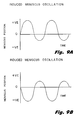
- the oscillations of the piezoelectric material 22 produce a constant, symmetric and continuous oscillation of the ink meniscus as shown in Figure 4B.
- These continuous, induced, symmetric and controlled meniscus oscillations of frequency, Fm, and amplitude, Im, in Figure 4B are superimposed on the "natural oscillations" in Figure 4A.
- the net result of this superposition of these two kinds of meniscus oscillations is a virtual "swamping out" of the natural meniscus oscillations in Figure 4A, and the virtual elimination of the "dead time", To, which is responsible for limiting the maximum operating frequency, F max , of the ink jet printhead.
- the timing of the firing of resistor 11 with respect to the meniscus amplitude, Im, of the induced meniscus oscillations is crucial. If the resistor 11 is fired at the equilibrium position, or points (T) in Figure 4B, the ink jet printhead is operating in the "equilibrium mode" and medium volume ink drops, Veq, are ejected. These ejected ink drops are of a volume equal to the case where the piezoelectric material is not pulsed.
- the maximum achievable operating frequency, F max of the ink jet printhead operating in the "equilibrium mode” is limited only by the frequency of induced meniscus oscillations, Fm.
- the resistor 11 is fired at the maximum meniscus extension position, namely at points (U) in Figure 4B, then the ink jet printhead is operating in the "rich mode” and maximum volume ink drops, V max , are ejected. If the resistor 11 is fired at the minimum meniscus extension position, which is point (V) in Figure 4B, then the ink jet printhead is operating in the "lean mode” and minimum volume ink drops, Vmin, are ejected. Firing the resistor 11 at different points between the rich and lean modes will cause ink drops to be ejected in varying and controlled volumes.
- the range of ejected ink drop volume may be extended by employing dual independently controlled piezoelectric systems within an ink jet printhead.
- Figure 7 illustrates such a system where both independently controlled piezoelectric drivers 22 are incorporated within the ink cavity 14.
- Figure 8 illustrates another system where the piezoelectric drivers 22 are incorporated both inside and outside the ink cavity 14, with the outside driver mounted on the orifice plate 16. The method of operation of both these systems in Figures 7 and 8 is the same.
- Each independently driven piezoelectric driver 22 may be energized with a controlled signal and caused to oscillate which in turn induces a symmetric meniscus oscillation as described above. If both piezoelectric drivers within an ink jet printhead are caused to oscillate in phase with each other and with equivalent amplitudes, then the induced meniscus oscillation remains symmetric as described above with reference to Figure 4B.
- both piezoelectric drivers 22 may be caused to: 1) oscillate out of phase with each other at the same frequency and amplitude; or 2) oscillate out of phase with each other at the same amplitude and with a different frequency.
- the combination of frequency, amplitude and phase shift may be selected to induce a meniscus oscillation which is asymmetric as shown in Figures 9A and 9B.
- the maximum volume ink drop, Vmax, ejected may be further extended from the symmetric case due to the greater meniscus extension in the asymmetric case.
- the limiting situation is attained when the asymmetric positive meniscus extension is so great that actual drop ejection begins to occur.
- Large positive asymmetric meniscus extensions may be favored by suitable choice of ink viscosity and surface energy of the ink.
- the minimum volume ink drop, Vmin, ejected may be further extended from the symmetric case.
- the limiting situation is attained when the asymmetric negative meniscus extension is so great that the printhead will begin to aspirate air through an orifice opening in the orifice plate of the printhead. Air aspiration may be modified by suitable choice of ink viscosity and ink surface energy.
- the pumping action of the added piezoelectric system described above enables the ink jet printhead to be used not only with current inks, with their low viscosities ( ⁇ about 3 cps) and higher surface tensions (> about 55 dyne/cm), but also with inks having a lower surface tension and a higher viscosity.
- higher viscosity inks penetrate slower into the surface of paper such that the print quality on a variety of papers, and particularly on xerographic or bond papers, is improved.
- Printheads using higher viscosity inks therefore print more consistently on a wider set of plain papers.
- the ability to use both high viscosity and low surface tension inks yield faster drytimes on plain papers as well.
- Standard ink technology which employs soluble dyes in a usually aqueous based vehicle, could be expanded to use a much larger group of allowable solvents.
- higher molecular weight glycols, ethers, ketones, and the like could be used in conjunction with water to obtain the desired vehicle properties.
- This expanded group of solvents allow dyes to be used in the new printhead described herein which are not currently acceptable because of solubility or reactivity with the ink vehicle. These additional dyes improve contrast, color, hue and print quality on the printed medium.
- non standard ink jet inks e.g. non-aqueous, dye based
- pigment based, microemulsion or encapsulation inks could be used.
- the present invention is not strictly limited to the specific printhead cross-section geometries shown and may be practiced using various printhead geometries including the well known "side shooter”, “face shooter” and “edge-shooter” constructions and the use of offsets between heater resistor center lines and orifice centers.
- the geometries of the ink feed channel and the ink reservoir cavities may be modified in accordance with the design constraints applicable to a variety of thermal ink jet printhead applications, and may include various state of the art hydraulic tuning and crosstalk reduction features.
Abstract
Description
- This invention relates generally to ink jet printing systems and more particularly to such systems employing auxiliary ink pumping means for improving operational performance. These systems are operative to maintain a positive pressure within an ink cavity and ink channel of an ink jet pen for extending its maximum operating frequency.
- In certain types of ink jet printing systems, such as thermal ink jet (TIJ) printers, the maximum achievable operating frequency, Fmax, is inherently limited by: 1) the inability of the natural capillary action in the ink feed apparatus to adequately supply ink to the ink reservoir chamber (the ink cavity) of the printhead and 2) by oscillations of the ink meniscus at the orifice plate of the printhead which persist for some time, To, after drop ejection has occurred. One approach to extending Fmax as well as providing other operational improvements in thermal ink jet printheads is disclosed and claimed in copending application Serial No. 120,300 of Marzio A. Leban et al entitled "Integral Thin Film Injection System For Thermal Ink Jet Heads and Method of Operation", filed November 13, 1987, assigned to the present assignee and incorporated herein by reference (European Application No. 88310572.8).
- Thermal ink jet printers having these operational characteristics are now generally well known in the art and are described, for example in the Hewlett-Packard Journal, Volume 38, No. 5, May 1985, incorporated herein by reference. These printers employ printhead devices having resistive heater elements (resistors) which are normally aligned with corresponding ink ejection orifices in an adjacent orifice plate and are operative to receive electrical drive pulses from an external source. These pulses rapidly heat the heater resistors and thereby cause ink in an adjacent ink reservoir to vaporize and be forced out of the orifice plate during an ink jet printing operation. Thus, as the operating frequency of the printhead is extended out beyond a certain limit, there is a tendency for the natural capillary action of the ink feed system of the TIJ printer to inadequately supply the required volume of ink to the ink reservoirs associated with the heater resistors, the adjacent ink cavity and ink channel feeding the cavity.
- This "ink starvation effect" becomes even more pronounced as the viscosity of the ink is increased. In many applications it is desirable to increase the ink viscosity in order to achieve an improved print quality on a variety of paper types and particularly plain paper. In addition to the above limitations imposed by this ink starvation effect, natural meniscus oscillations of the ink at the orifice further place a limitation on Fmax and persist for some time, To, immediately after a drop is ejected. During this time, To, further drop ejection is greatly restricted.
- Accordingly, it is an object of this invention to overcome the above inability of the natural ink feed capillary action to adequately supply ink to the ink jet printhead during high frequency operation and thereby extend Fmax beyond its present limits.
- Another object is to provide a new and improved printhead of the type described which is operative to generate meniscus oscillations of the ink at the orifice of a controlled frequency, Fm, and a controlled amplitude, Im. This action allows firing of ink drops of varying volume from the same orifice by timing the drop firing with meniscus height. Small drops are ejected when firing occurs at low meniscus levels, and large drops are ejected when firing occurs at high meniscus levels.
- Another object is to extend the upper limit of the usable ink viscosity. This is accomplished by employing the pumping action of a piezoelectric system to produce a positive pressure over and above the natural capillary force within the ink capillary cavity and ink capillary channel of the ink jet printhead.
- To achieve the above objects and attendant advantages of this invention, we have discovered and developed a new and improved ink feed system and method of operation for an ink jet printhead wherein the amplitude and frequency of oscillations of the meniscus at a fluid ejection orifice are controlled by ejecting fluid through an orifice and at a natural resonant frequency and amplitude with respect to an equilibrium position. The frequency or amplitude or both of the fluid meniscus at the orifice are modulated in a controlled phase relation with respect to the phase position of the oscillations of the meniscus above or below the equilibrium position.
- In a preferred embodiment of the invention, a resistive heater element is aligned with respect to an orifice plate, and an ink flow path supplies ink into a chamber or reservoir between the resistive heater element and the orifice plate. This improved system includes, among other things: 1) a piezoelectric system which is mounted internal to the ink cavity of an ink jet printhead; 2) an external piezoelectric system which is mounted directly on the orifice plate of an ink jet printhead; 3) dual independent piezoelectric systems which are both mounted internal to the ink cavity of the printhead; and 4) dual piezoelectric systems with one being internal to the ink cavity of the printhead and the other being external and mounted directly on the orifice plate of the printhead. The above described ink feed systems may be used to: 1) produce oscillations of controlled frequency, Fm, and controlled amplitude, Im, of the ink meniscus at the ink ejection orifice and produce the ejection of ink drops from a single orifice with varying and controlled volumes; 2) extend the maximum frequency of operation, Fmax, of the ink jet printhead; and 3) extend the viscosity range of inks which may be used.
- The above brief summary of invention will become better understood and appreciated from the following description of the accompanying drawing.
-
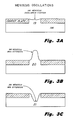
- Figure 1 is an abbreviated perspective view showing a typical mounting arrangement of a heater resistor within an ink feed channel.
- Figure 2 is an abbreviated cross section view showing the position of the heater resistor with respect to the main ink feed channel, the ink cavity and the orifice plate of the thermal ink jet printhead.
- Figures 3A-3C show, in abbreviated cross-section, three different meniscus positions during its oscillation at an orifice opening.
- Figures 4A-4B compare the natural meniscus oscillation with the induced meniscus oscillation provided in accordance with the present invention.
- Figure 5 is an abbreviated cross section view of an ink jet printhead which shows the piezoelectric pump material mounted within the ink cavity of the printhead.
- Figure 6 is an abbreviated cross section view of an ink jet printhead which shows the piezoelectric pump material mounted on the orifice plate of the printhead.
- Figure 7 is an abbreviated cross section view of an ink jet printhead which shows two (2) separate piezoelectric pump transducers mounted within the ink cavity of the printhead.
- Figure 8 is an abbreviated cross section view of an ink jet printhead which shows the piezoelectric pumps mounted on both the orifice plate outside the ink cavity and within the ink cavity of the printhead.
- Figures 9A-9B show the shifting of the induced meniscus oscillation about the meniscus equilibrium position by an amount controlled by the timing of pressure pulses generated by the piezoelectric pump or pumps of the ink jet printhead.
- Referring now to Figure 1, there is shown a perspective view of a single heater element (resistor) 11 surrounded by a
barrier material 12 forming anink channel 13 immediately adjacent to the resistor 11. Thebarrier material 12 also forms anink cavity region 14 exterior to theink channel 13. This type of three sided barrier layer construction is generally well known in the art and is disclosed for example in copending applications serial nos. 109,685 and 057,573 of Howard H. Taub et al assigned to the present assignee and incorporated herein by reference (European Application Nos. 88309820.4 and 88304048.7). - Figure 2 is a cross section view which would be taken through the center of the resistor in Figure 1 when the printhead structure therein, including the orifice plate, is completed. Figure 2 further illustrates that the
ink cavity 14 is formed between anunderlying substrate 15 and anouter orifice plate 16. Anorifice 17 is positioned immediately above the resistor 11, and ink from anink feed system 18 is drawn into theink cavity 14 and into theink channel 13 regions by a capillary force. - As the resistor 11 is fired by a suitable pulse applied thereto, a drop of ink is ejected from the
orifice 17. An ink jet printhead operating in this manner is considered to be operating in the "equilibrium mode". Immediately after drop ejection in the equilibrium mode, the meniscus of the ink at the 25orifice 17 will oscillate from theequilibrium position 19 as indicated in Figure 3A and achieves amaximum extension 20 and aminimum extension 21 as indicated in Figures 3B to 3C. These "natural oscillations" continue for a length of time, labeled the "dead time", To, with a decaying amplitude as shown in Figure 4A. During this time, ejection of an additional drop of ink is not permitted. - In accordance with the present invention, a
piezoelectric material 22 such as quartz or barium titanate crystals or a kynar piezoelectric film is introduced into theink cavity 14 as shown in Figure 5, or is mounted externally on the outer surface of theorifice plate 16 as shown in Figure 6. Thematerial 22 is connected in such a manner that it can be energized with a controlled electrical signal, and this signal induces oscillations, of controlled frequency and magnitude, within thematerial 22. This action in turn produces a positive ink pressure within theink cavity 14 and theink channel 13 and thereby behaves as an ink pump. Both internally and externally mounted piezoelectric systems function in an equivalent manner. - There are various available piezoelectric driving circuits suitable for providing the piezoelectric drive signals described herein, and the choice of circuit design of these drivers is considered well within the skill of the art. Therefore, a detailed description of specific driver circuit design has been omitted for sake of brevity. However, piezoelectric driver circuits have been described in many U.S. Patents, such as U.S. Patents 4,714,935, 4,717,927, 4,630,072, 4,498,089 and 4,521,786. Piezoelectric driver circuits have also been enclosed in the following four textbook references, and these four textbook references as well as the above patents are incorporated herein by reference:
- 1. Precision Frequency Control; E. A. Gerber, Ed. Academic Press, 1985.
- 2. Acoustic Waves: Devices, Imaging and Analogue Signal Devices; Gordon Kino, Prentice-Hall, 1987.
- 3. Standard Methods for the Measurement of Equivalent Circuits; American National Standards, Electronic Industries Association, 1985.
- 4. PVF2 - Models. Measurements, Device Ideas, John Linvill, Stanford Technical Report number 4834-3, Stanford University, 1978.
- The oscillations of the
piezoelectric material 22 produce a constant, symmetric and continuous oscillation of the ink meniscus as shown in Figure 4B. These continuous, induced, symmetric and controlled meniscus oscillations of frequency, Fm, and amplitude, Im, in Figure 4B are superimposed on the "natural oscillations" in Figure 4A. The net result of this superposition of these two kinds of meniscus oscillations is a virtual "swamping out" of the natural meniscus oscillations in Figure 4A, and the virtual elimination of the "dead time", To, which is responsible for limiting the maximum operating frequency, Fmax, of the ink jet printhead. - The timing of the firing of resistor 11 with respect to the meniscus amplitude, Im, of the induced meniscus oscillations is crucial. If the resistor 11 is fired at the equilibrium position, or points (T) in Figure 4B, the ink jet printhead is operating in the "equilibrium mode" and medium volume ink drops, Veq, are ejected. These ejected ink drops are of a volume equal to the case where the piezoelectric material is not pulsed. The maximum achievable operating frequency, Fmax, of the ink jet printhead operating in the "equilibrium mode" is limited only by the frequency of induced meniscus oscillations, Fm. If the resistor 11 is fired at the maximum meniscus extension position, namely at points (U) in Figure 4B, then the ink jet printhead is operating in the "rich mode" and maximum volume ink drops, Vmax, are ejected. If the resistor 11 is fired at the minimum meniscus extension position, which is point (V) in Figure 4B, then the ink jet printhead is operating in the "lean mode" and minimum volume ink drops, Vmin, are ejected. Firing the resistor 11 at different points between the rich and lean modes will cause ink drops to be ejected in varying and controlled volumes.
- The range of ejected ink drop volume may be extended by employing dual independently controlled piezoelectric systems within an ink jet printhead. Figure 7 illustrates such a system where both independently controlled
piezoelectric drivers 22 are incorporated within theink cavity 14. - Figure 8 illustrates another system where the
piezoelectric drivers 22 are incorporated both inside and outside theink cavity 14, with the outside driver mounted on theorifice plate 16. The method of operation of both these systems in Figures 7 and 8 is the same. - Each independently driven
piezoelectric driver 22 may be energized with a controlled signal and caused to oscillate which in turn induces a symmetric meniscus oscillation as described above. If both piezoelectric drivers within an ink jet printhead are caused to oscillate in phase with each other and with equivalent amplitudes, then the induced meniscus oscillation remains symmetric as described above with reference to Figure 4B. - Within the ink jet printhead, both
piezoelectric drivers 22 may be caused to: 1) oscillate out of phase with each other at the same frequency and amplitude; or 2) oscillate out of phase with each other at the same amplitude and with a different frequency. The combination of frequency, amplitude and phase shift may be selected to induce a meniscus oscillation which is asymmetric as shown in Figures 9A and 9B. - If the induced asymmetric meniscus oscillation is skewed to the positive as shown in Figure 9A, the maximum volume ink drop, Vmax, ejected may be further extended from the symmetric case due to the greater meniscus extension in the asymmetric case. The limiting situation is attained when the asymmetric positive meniscus extension is so great that actual drop ejection begins to occur. Large positive asymmetric meniscus extensions may be favored by suitable choice of ink viscosity and surface energy of the ink.
- Alternatively, if the asymmetric meniscus oscillation is skewed to the negative as shown in Figure 9B, the minimum volume ink drop, Vmin, ejected may be further extended from the symmetric case. The limiting situation is attained when the asymmetric negative meniscus extension is so great that the printhead will begin to aspirate air through an orifice opening in the orifice plate of the printhead. Air aspiration may be modified by suitable choice of ink viscosity and ink surface energy.
- The pumping action of the added piezoelectric system described above enables the ink jet printhead to be used not only with current inks, with their low viscosities (< about 3 cps) and higher surface tensions (> about 55 dyne/cm), but also with inks having a lower surface tension and a higher viscosity. Generally, higher viscosity inks penetrate slower into the surface of paper such that the print quality on a variety of papers, and particularly on xerographic or bond papers, is improved. Printheads using higher viscosity inks therefore print more consistently on a wider set of plain papers. The ability to use both high viscosity and low surface tension inks yield faster drytimes on plain papers as well.
- The ability to use higher viscosity inks with a lower surface tension has significant advantages over current technology. Standard ink technology, which employs soluble dyes in a usually aqueous based vehicle, could be expanded to use a much larger group of allowable solvents. For example, higher molecular weight glycols, ethers, ketones, and the like could be used in conjunction with water to obtain the desired vehicle properties. This expanded group of solvents allow dyes to be used in the new printhead described herein which are not currently acceptable because of solubility or reactivity with the ink vehicle. These additional dyes improve contrast, color, hue and print quality on the printed medium. Besides the improved print quality inherent in higher viscosity inks, other solvent and dye mixtures could yield improved waterfastness, reliability, smearfastness, lightfastness and archivability. Also, additional color dyes could be used, with a possible attendant improvement in color gamut and bleed characteristics.
- The ability to lower the requirements of surface tension and raise the allowable limit on viscosity would enable the printhead to be used with "non standard" ink jet inks (e.g. non-aqueous, dye based). For example, pigment based, microemulsion or encapsulation inks could be used. These new colorant systems would offer higher waterfastness, improved smearfastness, better color gamut, better reliability and better lightfastness and bleed.
- Various modifications may be made to the above described embodiments without departing from the scope of this invention. For example, the present invention is not strictly limited to the specific printhead cross-section geometries shown and may be practiced using various printhead geometries including the well known "side shooter", "face shooter" and "edge-shooter" constructions and the use of offsets between heater resistor center lines and orifice centers. Additionally, the geometries of the ink feed channel and the ink reservoir cavities may be modified in accordance with the design constraints applicable to a variety of thermal ink jet printhead applications, and may include various state of the art hydraulic tuning and crosstalk reduction features.
Claims (4)
Applications Claiming Priority (2)
| Application Number | Priority Date | Filing Date | Title |
|---|---|---|---|
| US23064488A | 1988-08-10 | 1988-08-10 | |
| US230644 | 1988-08-10 |
Publications (2)
| Publication Number | Publication Date |
|---|---|
| EP0354706A2 true EP0354706A2 (en) | 1990-02-14 |
| EP0354706A3 EP0354706A3 (en) | 1990-08-01 |
Family
ID=22866024
Family Applications (1)
| Application Number | Title | Priority Date | Filing Date |
|---|---|---|---|
| EP89307791A Withdrawn EP0354706A3 (en) | 1988-08-10 | 1989-08-01 | Ink flow control system and method for an ink jet printer |
Country Status (3)
| Country | Link |
|---|---|
| EP (1) | EP0354706A3 (en) |
| JP (1) | JPH0288246A (en) |
| CA (1) | CA1319561C (en) |
Cited By (11)
| Publication number | Priority date | Publication date | Assignee | Title |
|---|---|---|---|---|
| EP0510934A3 (en) * | 1991-04-26 | 1993-05-12 | Canon Kabushiki Kaisha | Ink jet recording apparatus and method capable of performing high-speed recording |
| EP0621135A1 (en) * | 1993-04-23 | 1994-10-26 | Brother Kogyo Kabushiki Kaisha | Ink jet apparatus |
| EP0678391A1 (en) * | 1994-03-08 | 1995-10-25 | Sony Corporation | Thermal transfer recording device |
| EP0738602A2 (en) * | 1995-04-21 | 1996-10-23 | Seiko Epson Corporation | Ink jet print head |
| US5828391A (en) * | 1994-03-08 | 1998-10-27 | Sony Corporation | Thermal transfer recording device |
| US6149259A (en) * | 1991-04-26 | 2000-11-21 | Canon Kabushiki Kaisha | Ink jet recording apparatus and method capable of performing high-speed recording |
| US6217159B1 (en) | 1995-04-21 | 2001-04-17 | Seiko Epson Corporation | Ink jet printing device |
| EP1172212A3 (en) * | 2000-07-11 | 2002-03-27 | Samsung Electronics Co., Ltd. | Bubble-jet type ink-jet printhead |
| EP1302319A3 (en) * | 2001-10-12 | 2004-01-02 | Eastman Kodak Company | Thermal actuator drop-on-demand apparatus and method with reduced energy |
| EP1510342A1 (en) * | 2003-09-01 | 2005-03-02 | Fuji Photo Film Co., Ltd. | Inkjet head and inkjet recording apparatus |
| WO2005102707A1 (en) * | 2004-04-14 | 2005-11-03 | Eastman Kodak Company | Apparatus and method of controlling droplet trajectory |
Families Citing this family (1)
| Publication number | Priority date | Publication date | Assignee | Title |
|---|---|---|---|---|
| BR112014004800B1 (en) * | 2011-08-31 | 2021-01-26 | Hewlett-Packard Development Company, L.P. | fluid ejection device and method for circulating fluid in a fluid ejection device |
Citations (4)
| Publication number | Priority date | Publication date | Assignee | Title |
|---|---|---|---|---|
| US4296421A (en) * | 1978-10-26 | 1981-10-20 | Canon Kabushiki Kaisha | Ink jet recording device using thermal propulsion and mechanical pressure changes |
| US4580149A (en) * | 1985-02-19 | 1986-04-01 | Xerox Corporation | Cavitational liquid impact printer |
| US4646110A (en) * | 1982-12-29 | 1987-02-24 | Canon Kabushiki Kaisha | Liquid injection recording apparatus |
| US4672398A (en) * | 1984-10-31 | 1987-06-09 | Hitachi Ltd. | Ink droplet expelling apparatus |
-
1989
- 1989-04-05 CA CA000595739A patent/CA1319561C/en not_active Expired - Fee Related
- 1989-08-01 EP EP89307791A patent/EP0354706A3/en not_active Withdrawn
- 1989-08-10 JP JP20778389A patent/JPH0288246A/en active Pending
Patent Citations (4)
| Publication number | Priority date | Publication date | Assignee | Title |
|---|---|---|---|---|
| US4296421A (en) * | 1978-10-26 | 1981-10-20 | Canon Kabushiki Kaisha | Ink jet recording device using thermal propulsion and mechanical pressure changes |
| US4646110A (en) * | 1982-12-29 | 1987-02-24 | Canon Kabushiki Kaisha | Liquid injection recording apparatus |
| US4672398A (en) * | 1984-10-31 | 1987-06-09 | Hitachi Ltd. | Ink droplet expelling apparatus |
| US4580149A (en) * | 1985-02-19 | 1986-04-01 | Xerox Corporation | Cavitational liquid impact printer |
Cited By (21)
| Publication number | Priority date | Publication date | Assignee | Title |
|---|---|---|---|---|
| US5280310A (en) * | 1991-04-26 | 1994-01-18 | Canon Kabushiki Kaisha | Ink jet recording apparatus and method capable of performing high-speed recording by controlling the meniscus of ink in discharging orifices |
| US5481281A (en) * | 1991-04-26 | 1996-01-02 | Canon Kabushiki Kaisha | Ink jet recording apparatus and method capable of performing high-speed recording |
| EP0510934A3 (en) * | 1991-04-26 | 1993-05-12 | Canon Kabushiki Kaisha | Ink jet recording apparatus and method capable of performing high-speed recording |
| US6149259A (en) * | 1991-04-26 | 2000-11-21 | Canon Kabushiki Kaisha | Ink jet recording apparatus and method capable of performing high-speed recording |
| EP0805027A2 (en) * | 1991-04-26 | 1997-11-05 | Canon Kabushiki Kaisha | Ink jet recording apparatus and method capable of performing high-speed recording |
| EP0805027A3 (en) * | 1991-04-26 | 1997-11-12 | Canon Kabushiki Kaisha | Ink jet recording apparatus and method capable of performing high-speed recording |
| EP0621135A1 (en) * | 1993-04-23 | 1994-10-26 | Brother Kogyo Kabushiki Kaisha | Ink jet apparatus |
| US5587727A (en) * | 1993-04-23 | 1996-12-24 | Brother Kogyo Kabushiki Kaisha | Ink jet apparatus using pressure wave intersection to eject ink droplets |
| US5828391A (en) * | 1994-03-08 | 1998-10-27 | Sony Corporation | Thermal transfer recording device |
| EP0678391A1 (en) * | 1994-03-08 | 1995-10-25 | Sony Corporation | Thermal transfer recording device |
| EP0738602A2 (en) * | 1995-04-21 | 1996-10-23 | Seiko Epson Corporation | Ink jet print head |
| EP0738602A3 (en) * | 1995-04-21 | 1997-06-11 | Seiko Epson Corp | Ink jet print head |
| US6217159B1 (en) | 1995-04-21 | 2001-04-17 | Seiko Epson Corporation | Ink jet printing device |
| US6382754B1 (en) | 1995-04-21 | 2002-05-07 | Seiko Epson Corporation | Ink jet printing device |
| EP1172212A3 (en) * | 2000-07-11 | 2002-03-27 | Samsung Electronics Co., Ltd. | Bubble-jet type ink-jet printhead |
| US6761433B2 (en) | 2000-07-11 | 2004-07-13 | Samsung Electronics Co., Ltd. | Bubble-jet type ink-jet printhead |
| EP1302319A3 (en) * | 2001-10-12 | 2004-01-02 | Eastman Kodak Company | Thermal actuator drop-on-demand apparatus and method with reduced energy |
| EP1510342A1 (en) * | 2003-09-01 | 2005-03-02 | Fuji Photo Film Co., Ltd. | Inkjet head and inkjet recording apparatus |
| US7270403B2 (en) | 2003-09-01 | 2007-09-18 | Fujifilm Corporation | Inkjet head and inkjet recording apparatus |
| WO2005102707A1 (en) * | 2004-04-14 | 2005-11-03 | Eastman Kodak Company | Apparatus and method of controlling droplet trajectory |
| US7364277B2 (en) | 2004-04-14 | 2008-04-29 | Eastman Kodak Company | Apparatus and method of controlling droplet trajectory |
Also Published As
| Publication number | Publication date |
|---|---|
| EP0354706A3 (en) | 1990-08-01 |
| CA1319561C (en) | 1993-06-29 |
| JPH0288246A (en) | 1990-03-28 |
Similar Documents
| Publication | Publication Date | Title |
|---|---|---|
| US5023625A (en) | Ink flow control system and method for an ink jet printer | |
| US5155498A (en) | Method of operating an ink jet to reduce print quality degradation resulting from rectified diffusion | |
| EP0739742B1 (en) | Liquid jet recording apparatus capable of recording better half tone image density | |
| EP0580154B1 (en) | Method for forming ink droplets in ink-jet type printer and ink-jet type recording device | |
| EP0437106B1 (en) | Method and apparatus for printing with ink drops of varying sizes using a drop-on-demand ink jet print head | |
| EP1620269B1 (en) | Image reproducing/forming apparatus with print head operated under improved driving waveform | |
| US4492968A (en) | Dynamic control of nonlinear ink properties for drop-on-demand ink jet operation | |
| CA1319561C (en) | Ink flow control system and method for an ink jet printer | |
| JPH05201024A (en) | Ink jet print head and ink jet printer | |
| JP3763200B2 (en) | Inkjet recording device | |
| US6419336B1 (en) | Ink ejector | |
| EP0271904B1 (en) | Liquid injection recording method | |
| US6609784B2 (en) | Ink jet recording device and a method for designing the same | |
| JP2003237066A (en) | Head driving control device and image recorder | |
| JP2785727B2 (en) | Ink jet print head and driving method thereof | |
| US6450602B1 (en) | Electrical drive waveform for close drop formation | |
| JP4187150B2 (en) | Droplet discharge head and image forming apparatus | |
| JPH1029321A (en) | Ink jet printer and printing method | |
| JP3554110B2 (en) | Ink jet recording device | |
| US20120139999A1 (en) | Liquid ejecting head and liquid ejecting apparatus | |
| JP2002178510A (en) | Ink jet recorder | |
| JP2004058300A (en) | Inkjet recorder | |
| JP2003291334A (en) | Ink jet recorder and method for driving recording head in ink jet recorder | |
| JP2001287347A (en) | Method for driving ink jet recording head and ink jet recorder | |
| JP2003127370A (en) | Ink jet recorder |
Legal Events
| Date | Code | Title | Description |
|---|---|---|---|
| PUAI | Public reference made under article 153(3) epc to a published international application that has entered the european phase |
Free format text: ORIGINAL CODE: 0009012 |
|
| AK | Designated contracting states |
Kind code of ref document: A2 Designated state(s): DE FR GB IT |
|
| PUAL | Search report despatched |
Free format text: ORIGINAL CODE: 0009013 |
|
| RHK1 | Main classification (correction) |
Ipc: B41J 2/045 |
|
| AK | Designated contracting states |
Kind code of ref document: A3 Designated state(s): DE FR GB IT |
|
| 17P | Request for examination filed |
Effective date: 19901220 |
|
| 17Q | First examination report despatched |
Effective date: 19920804 |
|
| STAA | Information on the status of an ep patent application or granted ep patent |
Free format text: STATUS: THE APPLICATION IS DEEMED TO BE WITHDRAWN |
|
| 18D | Application deemed to be withdrawn |
Effective date: 19930316 |