EP0357291A2 - Crankless reciprocating machine - Google Patents
Crankless reciprocating machine Download PDFInfo
- Publication number
- EP0357291A2 EP0357291A2 EP89308304A EP89308304A EP0357291A2 EP 0357291 A2 EP0357291 A2 EP 0357291A2 EP 89308304 A EP89308304 A EP 89308304A EP 89308304 A EP89308304 A EP 89308304A EP 0357291 A2 EP0357291 A2 EP 0357291A2
- Authority
- EP
- European Patent Office
- Prior art keywords
- cylinder
- pistons
- engine
- main shaft
- fuel
- Prior art date
- Legal status (The legal status is an assumption and is not a legal conclusion. Google has not performed a legal analysis and makes no representation as to the accuracy of the status listed.)
- Granted
Links
Images


Classifications
-
- F—MECHANICAL ENGINEERING; LIGHTING; HEATING; WEAPONS; BLASTING
- F01—MACHINES OR ENGINES IN GENERAL; ENGINE PLANTS IN GENERAL; STEAM ENGINES
- F01B—MACHINES OR ENGINES, IN GENERAL OR OF POSITIVE-DISPLACEMENT TYPE, e.g. STEAM ENGINES
- F01B3/00—Reciprocating-piston machines or engines with cylinder axes coaxial with, or parallel or inclined to, main shaft axis
- F01B3/0002—Reciprocating-piston machines or engines with cylinder axes coaxial with, or parallel or inclined to, main shaft axis having stationary cylinders
- F01B3/0005—Reciprocating-piston machines or engines with cylinder axes coaxial with, or parallel or inclined to, main shaft axis having stationary cylinders having two or more sets of cylinders or pistons
-
- F—MECHANICAL ENGINEERING; LIGHTING; HEATING; WEAPONS; BLASTING
- F01—MACHINES OR ENGINES IN GENERAL; ENGINE PLANTS IN GENERAL; STEAM ENGINES
- F01B—MACHINES OR ENGINES, IN GENERAL OR OF POSITIVE-DISPLACEMENT TYPE, e.g. STEAM ENGINES
- F01B3/00—Reciprocating-piston machines or engines with cylinder axes coaxial with, or parallel or inclined to, main shaft axis
- F01B3/04—Reciprocating-piston machines or engines with cylinder axes coaxial with, or parallel or inclined to, main shaft axis the piston motion being transmitted by curved surfaces
- F01B3/045—Reciprocating-piston machines or engines with cylinder axes coaxial with, or parallel or inclined to, main shaft axis the piston motion being transmitted by curved surfaces by two or more curved surfaces, e.g. for two or more pistons in one cylinder
-
- F—MECHANICAL ENGINEERING; LIGHTING; HEATING; WEAPONS; BLASTING
- F02—COMBUSTION ENGINES; HOT-GAS OR COMBUSTION-PRODUCT ENGINE PLANTS
- F02B—INTERNAL-COMBUSTION PISTON ENGINES; COMBUSTION ENGINES IN GENERAL
- F02B1/00—Engines characterised by fuel-air mixture compression
- F02B1/02—Engines characterised by fuel-air mixture compression with positive ignition
- F02B1/04—Engines characterised by fuel-air mixture compression with positive ignition with fuel-air mixture admission into cylinder
-
- F—MECHANICAL ENGINEERING; LIGHTING; HEATING; WEAPONS; BLASTING
- F02—COMBUSTION ENGINES; HOT-GAS OR COMBUSTION-PRODUCT ENGINE PLANTS
- F02B—INTERNAL-COMBUSTION PISTON ENGINES; COMBUSTION ENGINES IN GENERAL
- F02B75/00—Other engines
- F02B75/02—Engines characterised by their cycles, e.g. six-stroke
- F02B2075/022—Engines characterised by their cycles, e.g. six-stroke having less than six strokes per cycle
- F02B2075/025—Engines characterised by their cycles, e.g. six-stroke having less than six strokes per cycle two
-
- F—MECHANICAL ENGINEERING; LIGHTING; HEATING; WEAPONS; BLASTING
- F02—COMBUSTION ENGINES; HOT-GAS OR COMBUSTION-PRODUCT ENGINE PLANTS
- F02B—INTERNAL-COMBUSTION PISTON ENGINES; COMBUSTION ENGINES IN GENERAL
- F02B75/00—Other engines
- F02B75/26—Engines with cylinder axes coaxial with, or parallel or inclined to, main-shaft axis; Engines with cylinder axes arranged substantially tangentially to a circle centred on main-shaft axis
Definitions
- the invention relates to a crankless reciprocating machine having one or more cylinders, each of which houses two opposed pistons arranged to reciprocate in opposite directions along the longitudinal axis of the cylinder.
- a main shaft is disposed parallel to, and spaced from, the longitudinal axis of each cylinder.
- the main shaft and pistons are so interconnected that reciprocation of the pistons imparts rotary motion to the main shaft or vice versa.
- the machine of the invention may be an internal combustion engine and, in particular, a two stroke internal combustion engine.
- Engines may be adapted to a wide range of fuels such as petrol, diesel or gas. It is also within the scope of this invention to adapt the machine for use as a steam engine or an engine employing compressed gas. Further, the machine may be adapted to operate as a compressor or pump.
- crank mechanisms Conventional reciprocating machines generally use a crank mechanism to convert reciprocating motion into rotary motion or vice versa. Crank mechanisms entail energy loss causing lower efficiency and the inherent imbalance of them causes noise, vibration and wear. Generally it is necessary to employ balancing counterweights.
- the invention can be a two stroke sinusoidal or modified swashplate internal combustion engine.
- the engine is sinusoidal in that conventional crank shaft design is replaced by an endless sinusoidal or substantially sinusoidal track.
- a sinusoidal track may be used to produce perfect simple harmonic motion.
- the motion of the pistons may also be modified.
- a designer is able to dictate the motion of the pistons.
- a crankless reciprocating machine comprises at least one cylinder, two opposed pistons arranged to reciprocate in opposite directions along the longitudinal axis of each cylinder, the pistons defining a common working chamber therebetween, a main shaft disposed parallel to, and spaced from, the longitudinal axis of each cylinder, two axially spaced, endless, substantially sinusoidal tracks carried by the main shaft for rotation therewith, said tracks being interconnected with said pistons so that reciprocation of the pistons imparts rotary motion to the main shaft and vice versa, characterised in that said substantially sinusoidal tracks are axially spaced from each cylinder and each comprises a radially extending flange contoured in an axial direction to define the endless, substantially sinusoidal track, the radially extending faces of the flange forming opposed, axially facing, endless, substantially sinusoidal cam surfaces, a connecting rod connected at one end to each piston, bearing means carried toward the other end of said connecting rod, said bearing means abutting each of the two opposed axially facing cam surfaces.
- the internal combustion engine may have a single cylinder with two opposed pistons which reciprocate in opposite directions along the longitudinal axis of the cylinder.
- the engine may have a plurality of such cylinders.
- the axis of each cylinder is arranged parallel to the drive shaft and spaced therefrom.
- they may be arranged in a circle around the drive shaft.
- the engine is dynamically balanced regardless of the number of cylinders.
- Each cylinder is itself dynamically balanced and requires no counterweights.
- the section plane is through the centre line of the lower cylinder and through both sumps. There is also a part section through the centre line on the poppet valve chamber on the upper cylinder.
- the two stroke internal combustion engine illustrated in Fig. 1 comprises two cylinders 4 disposed on opposite sides of a main shaft 1 which is mounted for rotation about a horizontal axis in bearings 12.
- the terms “axial” and “radial” have reference to the longitudinal axis of main shaft 1.
- Each wheel 2 has a radial flange 3 extending radially outwardly from its cylindrical surface.
- Flange 3 is contoured in an axial direction so that it traces an endless, substantially sinusoidal path around the cylindrical surface of wheel 2.
- the two flanges 3 are identical, one being the mirror image of the other.
- the radial surfaces of flange 3 form two, opposed, axially facing cam surfaces 3 ⁇ each of which also traces an endless, substantially sinusoidal path around wheel 2.
- Each cylinder 4 and its reciprocating pistons 5 are of the same construction. However, in Fig. 1 the pistons 5 in the top cylinder 4 operate 180° out of phase with the pistons 5 in the bottom cylinder 4. The description will mainly be made in reference of one cylinder 4.
- each cylinder 4 Mounted within each cylinder 4 is a pair of opposed pistons 5 which are adapted to reciprocate in opposite directions along the longitudinal axis of cylinder 4. Rigidly connected to each piston 5 is a connecting rod 6 which is adapted to co-operate with an endless sinusoidal track 3 by way of two drive bearings 8 and a tail bearing 9. The engine is closed at each end by sump casings 7.
- connecting rod 6 is bifurcated to provide a mounting for one drive bearing 8 on each arm.
- the outer of the bifurcated arms extends beyond sinusoidal flange 3 to provide a mounting for tail bearing 9.
- the outer bifurcated arm of connecting rod 6 has two lateral arms to provide mountings for a pair of guide bearings 11 which run in parallel tracks 10 formed in members which are integral with cylinder 4 and project outwardly at the end thereof. Guide bearings 11 are firmly supported in tracks 10 and thus resist unwanted movement of connecting rod 6 and rotation of piston 5 in its cylinder 4.
- flange 3 With a continuously variable thickness. In the position shown in Fig. 1, flange 3 is thickest at the top and bottom portions and thinner therebetween. In addition, it is also preferred to taper flange 3, drive bearings 8 and tail bearing 9 so as to provide a uniform relative velocity across the contact faces and thus minimise wear.
- Pistons 5 define a common combustion chamber 13 therebetween.
- a charge and ignition chamber 14 fuel rich chamber
- a spark plug 16 is mounted on chamber 14 for ignition of fuel therein.
- a poppet valve 17 controls the admission of fuel into the charge and ignition chamber 14. The condition of poppet valve 17 is controlled by a valve spring housed in chamber 18 and by a push rod 19 whose position is controlled by a cam 20 on the left wheel 2. A similar cam is not required on right wheel 2.
- Cylinder 4 is provided with a scavenge port 21 communicating with a scavenge manifold 22 and an exhaust port 23 communicating with an exhaust manifold 24.
- the graph of Fig. 3 represents piston motion during one revolution of shaft 1 when a two stroke cycle is completed. From points A to B, tracks 3 are modified to allow pistons 5 to remain at outer dead centre while sinusoidal tracks 3 continue to rotate under the influence of rotational inertia, supplied by the wheels 2 and, if desired, by an external fly wheel (not shown).
- an air blast is supplied by an external means (not shown) which may be a Rootes blower or similar device. The air blast passes into cylinder 4 by way of scavenge manifold 22 and the open scavenge port 21. Spent gases from the previous cycle are expelled to the exhaust manifold 24 by way of the open exhaust port 23. This air charge also acts as a coolant.
- pistons 5 move inwards with substantially simple harmonic motion coming momentarily to rest again at C. Pistons 5 have now advanced along cylinder 4 shutting off ports 21 and 23. Trapped between pistons 5 is a volume of clean but cold air. As the pistons 5 approach point C, poppet valve 17 is opened under the action of cam 20.
- tracks 3 are modified to cause pistons 5 to stop again for a given period of angular rotation.
- Cold air which is supplied from the same source as the scavenge air, is injected with petrol or gas and flows to the charge and ignition chamber 14 by way of open poppet valve 17.
- This air/fuel mixture which contains a fuel rich ratio, will pass through orifice 15 into the lean combustion chamber 13 while poppet valve 17 remains open.
- the purpose of the two chambers 13 and 14 is to provide "stratification" for improved fuel economy and reduced toxic emissions.
- the air/fuel mixture remaining in the charge and ignition chamber 14 when poppet valve 17 closes is a small volume of fuel rich mixture capable of ignition by a spark plug 16.
- the larger fuel volume on passing into chamber 13 becomes diluted due to the presence of scavenge air which is trapped in combustion chamber 13 when ports 21 and 23 close.
- the diluted fuel /air mixture is not capable of ignition by a spark plug but will ignite following the ignition of the mixture in chamber 14. This avoids the need to have the entire mixture rich in fuel as in conventional systems and should lead to a 30% reduction in fuel consumption.
- Stratified combustion requires the fuel rich chamber 14 be small so as to prevent movement of the diluted mixture from combustion chamber 13 into chamber 14 during compression. The smaller the chamber, the less fuel consumed, as only a small quantity of rich mixture in close contact with the spark plug is required for ignition. Further, high temperature is largely confined to charge and ignition chamber 14 where combustion commences.
- the combustion chambers undergo supercharge.
- the shape of track 3 during this phase determines the period of piston dwell. Accordingly, by an appropriate selection of track shape, it is possible to supercharge to any predetermined pressure thereby allowing the engine to operate at optimum pressure equivalent to the maximum safe compression ratio when burning petrol.
- exhaust port 23 opens first, followed fractionally later by air scavenge port 21.
- the cycle as shown in Fig. 3 may be modified for specific applications as in piston aircraft engines. For this application, revs are restricted due to excessive propeller tip speeds. Hence maximum torque is desirable at the lowest possible engine revs. Therefore if the cycle shown in Fig. 3 represents 360°, it could be desirable to reduce A to A to 180° and supply two such cycles in 360°. This modification would double the torque output and halve the revs allowing a much more powerful engine to be installed at allowable propeller speed with substantial weight reduction.
- the engine is capable of changing to diesel fuel consumption with little modification. This conversion, and the reverse conversion, could be executed in minutes. The cycle remains the same as for petrol or gas with the following exceptions.
- diesel fuel is admitted by a conventional nozzle into the charge ignition chamber 14.
- a glow plug is fitted alongside the spark plug 16 or a combined spark plug - glow plug could be provided for this multi-fuel engine.
- the intended fuels to be used in a multi-fuel engine are methanol, natural gas, producer gas, petrol and diesel.
- the first four fuels require the provision of a spark plug, while diesel will require a glow plug.
- Both the spark and glow plugs need to be located in the fuel rich chamber, which, due to its small size presents a space problem. It is therefore expedient to combine both units into a normal size of spark plug.
- Such a device is shown in Fig. 5.
- heating current is introduced at 2′ providing the necessary heat at lower end 4′ of the electrode.
- the negative terminal for this current will be the plug body 1′.
- spark plug high voltage current will flow through electrode 3′and spark to the common negative terminal 1′.
- an external flywheel may be coupled to the drive shaft by, for example, magnetic coupling or fluid coupling or similar device.
- FIG. 4 shows another internal combustion engine having two cylinders.
- ports 24′ are both exhaust ports and are symmetrically positioned with respect to cylinder 4 and communicate with exhaust manifolds 25′. This allows more rapid exhausting of combustion chamber 13 at high speed and a more uniform heat dissipation.
- the ignition components are as described in Fig. 1, except that the orifice from the fuel rich chamber 14 is referenced 22′, spark plug 16 is mounted radially and its poppet valve 17 is controlled by cam 20 on right wheel 2.
- the admission of scavenge air is controlled by a similar arrangement. Scavenge air is now provided via a second spring loaded poppet valve l7′ which is operated via push rod 19′ by a cam 21′ on the left hand wheel 2. After passing poppet valve 17′, scavenge air flows through scavenge air orifice 23′.
- the scavenge air orifice 23′ is substantially larger than air/fuel orifice 22′ to ensure free air flow for scavenging with a minimum of resistance. Further, during fuel charging, smaller air/fuel orifice 22′ ensures separation of the rich and lean fuel mixtures for stratification. Orifices 22′ and 23′ join and lead to a common orifice 15 to combustion chamber 13.
- main shaft in this type of machine is highly stressed in axial tension and bending.
- the bending stress is more severe.
- main shaft 1 is made hollow and a second shaft 26 is mounted in bearings 27 at each end within hollow main shaft 1.
- Shaft 26 becomes the output shaft.
- a wet multi-plate clutch 28 with compression springs 29 is mounted within a clutch housing 30 on the right wheel 2.
- clutch 28 When clutch 28 is engaged, drive is conveyed from main shaft 1 to output shaft 26.
- This arrangement also allows the gearbox to become an integral part of the left sump located next to the left wheel 2.
- the overall effect is a significant shortening of the engine and the elimination of a number of oil seals generally regarded as a nuisance in conventional engines.
- Fig. 6 illustrates an alternative guide system for connecting rod 6 which is favourable in terms of eliminating some moving parts.
- a gudgeon pin is used to connect connecting rod 6 to piston 5.
- a robust rigid drag link 31 is at one end pivoted to part of cylinder 4. This end is preferrably deepened and a long pivot pin is employed to eliminate any lateral movement of drag link 31.
- the other end of drag link 31 is pivoted to the pivot pin of drive bearing 8.
- the robust nature of drag link 31 and the pivoted connections at each end resist rotation of piston 5 in cylinder 4. Since the outer end of connecting rod 6 moves in a circular arc, tail bearing 9 is spring loaded at 32 to facilitate the drive bearing 8 and tail bearing 9 to negotiate the sinusoidal track.
Abstract
Description
- The invention relates to a crankless reciprocating machine having one or more cylinders, each of which houses two opposed pistons arranged to reciprocate in opposite directions along the longitudinal axis of the cylinder. A main shaft is disposed parallel to, and spaced from, the longitudinal axis of each cylinder. The main shaft and pistons are so interconnected that reciprocation of the pistons imparts rotary motion to the main shaft or vice versa.
- The machine of the invention may be an internal combustion engine and, in particular, a two stroke internal combustion engine. Engines may be adapted to a wide range of fuels such as petrol, diesel or gas. It is also within the scope of this invention to adapt the machine for use as a steam engine or an engine employing compressed gas. Further, the machine may be adapted to operate as a compressor or pump.
- Conventional reciprocating machines generally use a crank mechanism to convert reciprocating motion into rotary motion or vice versa. Crank mechanisms entail energy loss causing lower efficiency and the inherent imbalance of them causes noise, vibration and wear. Generally it is necessary to employ balancing counterweights.
- It has been proposed in U.S. Patent 3598094 (ODAWARA) to provide a crankless reciprocating machine with a mechanism for converting a reciprocating motion into a rotary motion or vice versa. The mechanism comprises a pin rigidly connected to a piston and extending radially outwardly therefrom. An endless cam groove is formed in a part which surrounds the piston. The pin travels in the endless cam groove so that reciprocating motion of the piston produces rotary motion of a rotating part.
- The use of a pin running in an endless groove is also described in U.S. Patents 1529687 (BOWEN), 2401466 (DAVIS ET AL) and 4090478 (TRIMBLE).
- These suffer a disadvantage that forces acting on the pin change direction on each occasion the piston reverses direction. This results in a wear problem and loss of movement control. These engines involve complexities in construction, particularly in the cylinders.
- The invention can be a two stroke sinusoidal or modified swashplate internal combustion engine. The engine is sinusoidal in that conventional crank shaft design is replaced by an endless sinusoidal or substantially sinusoidal track. A sinusoidal track may be used to produce perfect simple harmonic motion.
- Alternatively, by modifying the configuration of the track, the motion of the pistons may also be modified. Thus, by employing a substantially sinusoidal track, a designer is able to dictate the motion of the pistons.
- A crankless reciprocating machine comprises at least one cylinder, two opposed pistons arranged to reciprocate in opposite directions along the longitudinal axis of each cylinder, the pistons defining a common working chamber therebetween, a main shaft disposed parallel to, and spaced from, the longitudinal axis of each cylinder, two axially spaced, endless, substantially sinusoidal tracks carried by the main shaft for rotation therewith, said tracks being interconnected with said pistons so that reciprocation of the pistons imparts rotary motion to the main shaft and vice versa, characterised in that said substantially sinusoidal tracks are axially spaced from each cylinder and each comprises a radially extending flange contoured in an axial direction to define the endless, substantially sinusoidal track, the radially extending faces of the flange forming opposed, axially facing, endless, substantially sinusoidal cam surfaces, a connecting rod connected at one end to each piston, bearing means carried toward the other end of said connecting rod, said bearing means abutting each of the two opposed axially facing cam surfaces.
- The internal combustion engine may have a single cylinder with two opposed pistons which reciprocate in opposite directions along the longitudinal axis of the cylinder. Alternatively, the engine may have a plurality of such cylinders. In either case, the axis of each cylinder is arranged parallel to the drive shaft and spaced therefrom. In the case of three or more cylinders, they may be arranged in a circle around the drive shaft. The engine is dynamically balanced regardless of the number of cylinders. Each cylinder is itself dynamically balanced and requires no counterweights.
- The invention is now described with reference to the accompanying drawings in which -
- Fig. 1 illustrates one embodiment of the invention and shows a part plan - part sectional view of a two stroke internal combustion engine having two cylinders;
- Fig. 2 shows a sectional view (normal to the section of Fig. 1) of the connecting rod guide system of the engine of Fig. 1;
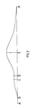
- Fig. 3 is a graphical representation of the piston motion during a complete two stroke cycle of the engine of Fig. 1;
- Fig. 4 is a view similar to that of Fig. 1 and illustrates a second internal combustion engine;
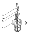
- Fig. 5 is a sectional view of a combined spark plug-glow plug for use in a multi-fuel engine; and
- Fig. 6 illustrates an alternative connecting rod guide system to that shown in Fig. 2.
- In Fig. 1, the section plane is through the centre line of the lower cylinder and through both sumps. There is also a part section through the centre line on the poppet valve chamber on the upper cylinder.
- The two stroke internal combustion engine illustrated in Fig. 1 comprises two
cylinders 4 disposed on opposite sides of amain shaft 1 which is mounted for rotation about a horizontal axis inbearings 12. In the description and claims, the terms "axial" and "radial" have reference to the longitudinal axis ofmain shaft 1. - Fixed to
main shaft 1 for rotation therewith is a pair of spacedwheels 2 having similar outer cylindrical surfaces. Eachwheel 2 has aradial flange 3 extending radially outwardly from its cylindrical surface.Flange 3 is contoured in an axial direction so that it traces an endless, substantially sinusoidal path around the cylindrical surface ofwheel 2. The twoflanges 3 are identical, one being the mirror image of the other. The radial surfaces offlange 3 form two, opposed, axially facingcam surfaces 3˝ each of which also traces an endless, substantially sinusoidal path aroundwheel 2. - Each
cylinder 4 and its reciprocatingpistons 5 are of the same construction. However, in Fig. 1 thepistons 5 in thetop cylinder 4 operate 180° out of phase with thepistons 5 in thebottom cylinder 4. The description will mainly be made in reference of onecylinder 4. - Mounted within each
cylinder 4 is a pair ofopposed pistons 5 which are adapted to reciprocate in opposite directions along the longitudinal axis ofcylinder 4. Rigidly connected to eachpiston 5 is a connectingrod 6 which is adapted to co-operate with an endlesssinusoidal track 3 by way of twodrive bearings 8 and a tail bearing 9. The engine is closed at each end bysump casings 7. - As shown in Fig. 1, the distal end of connecting
rod 6 is bifurcated to provide a mounting for one drive bearing 8 on each arm. The outer of the bifurcated arms extends beyondsinusoidal flange 3 to provide a mounting for tail bearing 9. As shown in Fig. 2, the outer bifurcated arm of connectingrod 6 has two lateral arms to provide mountings for a pair ofguide bearings 11 which run inparallel tracks 10 formed in members which are integral withcylinder 4 and project outwardly at the end thereof.Guide bearings 11 are firmly supported intracks 10 and thus resist unwanted movement of connectingrod 6 and rotation ofpiston 5 in itscylinder 4.Drive bearings 8 and tail bearing 9 abut respective opposed, axially facing, cam surfaces offlange 3, which is firmly held between the bearings to minimise any unwanted movement therebetween. To compensate for the sinusoidal curvature offlange 3, and to match the thickness offlange 3 with the spacing betweendrive bearings 8 and tail bearing 9, it is preferred to formflange 3 with a continuously variable thickness. In the position shown in Fig. 1,flange 3 is thickest at the top and bottom portions and thinner therebetween. In addition, it is also preferred to taperflange 3,drive bearings 8 and tail bearing 9 so as to provide a uniform relative velocity across the contact faces and thus minimise wear. - Pistons 5 define a
common combustion chamber 13 therebetween. Mounted adjacent to each cylinder is a charge and ignition chamber 14 (fuel rich chamber) provided with anorifice 15 for communication with thecombustion chamber 13. Aspark plug 16 is mounted onchamber 14 for ignition of fuel therein. Apoppet valve 17 controls the admission of fuel into the charge andignition chamber 14. The condition ofpoppet valve 17 is controlled by a valve spring housed inchamber 18 and by apush rod 19 whose position is controlled by acam 20 on theleft wheel 2. A similar cam is not required onright wheel 2. -
Cylinder 4 is provided with ascavenge port 21 communicating with ascavenge manifold 22 and anexhaust port 23 communicating with anexhaust manifold 24. - Operation of the engine is described in relation to petrol or gas fuel. The graph of Fig. 3 represents piston motion during one revolution of
shaft 1 when a two stroke cycle is completed. From points A to B, tracks 3 are modified to allowpistons 5 to remain at outer dead centre whilesinusoidal tracks 3 continue to rotate under the influence of rotational inertia, supplied by thewheels 2 and, if desired, by an external fly wheel (not shown). For scavenging purposes, an air blast is supplied by an external means (not shown) which may be a Rootes blower or similar device. The air blast passes intocylinder 4 by way ofscavenge manifold 22 and theopen scavenge port 21. Spent gases from the previous cycle are expelled to theexhaust manifold 24 by way of theopen exhaust port 23. This air charge also acts as a coolant. - From B to C of Fig. 3,
pistons 5 move inwards with substantially simple harmonic motion coming momentarily to rest again atC. Pistons 5 have now advanced alongcylinder 4 shutting offports pistons 5 is a volume of clean but cold air. As thepistons 5 approach point C,poppet valve 17 is opened under the action ofcam 20. - From point C to D, tracks 3 are modified to cause
pistons 5 to stop again for a given period of angular rotation. Cold air, which is supplied from the same source as the scavenge air, is injected with petrol or gas and flows to the charge andignition chamber 14 by way ofopen poppet valve 17. This air/fuel mixture which contains a fuel rich ratio, will pass throughorifice 15 into thelean combustion chamber 13 whilepoppet valve 17 remains open. The purpose of the twochambers ignition chamber 14 whenpoppet valve 17 closes is a small volume of fuel rich mixture capable of ignition by aspark plug 16. The larger fuel volume on passing intochamber 13 becomes diluted due to the presence of scavenge air which is trapped incombustion chamber 13 whenports chamber 14. This avoids the need to have the entire mixture rich in fuel as in conventional systems and should lead to a 30% reduction in fuel consumption. Stratified combustion requires the fuelrich chamber 14 be small so as to prevent movement of the diluted mixture fromcombustion chamber 13 intochamber 14 during compression. The smaller the chamber, the less fuel consumed, as only a small quantity of rich mixture in close contact with the spark plug is required for ignition. Further, high temperature is largely confined to charge andignition chamber 14 where combustion commences. The air incombustion chamber 13, being cold ( and thus more dense than a hot charge), provides a high density charge and this leads to a very high volumetric efficiency. During this charging process, becauseports pistons 5, the combustion chambers undergo supercharge. The shape oftrack 3 during this phase determines the period of piston dwell. Accordingly, by an appropriate selection of track shape, it is possible to supercharge to any predetermined pressure thereby allowing the engine to operate at optimum pressure equivalent to the maximum safe compression ratio when burning petrol. - From points D to E, the pistons move inwards with simple harmonic motion.
Poppet valve 17 closes early in this motion. Ignition takes place at E or just before as gases reach maximum compression at inner dead centre. - From points E to A, there is gas expansion in the combustion chamber and
pistons 5 act upon the sinusoidal curves via connectingrods 6 and drivebearings 8 imparting a rotary motion to thewheels 2 andmain shaft 1. It will be noted from Fig. 3 that a greater angular arc is given to expansion as compared to compression. This allows a greater period of time for combustion and hence to the imparting of energy to themain shaft 1. - As
pistons 5 approach A,exhaust port 23 opens first, followed fractionally later byair scavenge port 21. The cycle as shown in Fig. 3 may be modified for specific applications as in piston aircraft engines. For this application, revs are restricted due to excessive propeller tip speeds. Hence maximum torque is desirable at the lowest possible engine revs. Therefore if the cycle shown in Fig. 3 represents 360°, it could be desirable to reduce A to A to 180° and supply two such cycles in 360°. This modification would double the torque output and halve the revs allowing a much more powerful engine to be installed at allowable propeller speed with substantial weight reduction. - The engine is capable of changing to diesel fuel consumption with little modification. This conversion, and the reverse conversion, could be executed in minutes. The cycle remains the same as for petrol or gas with the following exceptions.
- From point C to D, it is necessary to provide for a higher compression ratio of at least 16:1. Accordingly, the air supplied must be increased in pressure to provide a higher supercharge. For this purpose, there may be provided a second blower to come into operation in series with the first. No fuel is admitted during this charge and provision must be made for isolating petrol and/or gas.
- From points E to some point approaching A, diesel fuel is admitted by a conventional nozzle into the
charge ignition chamber 14. For cold starting, a glow plug is fitted alongside thespark plug 16 or a combined spark plug - glow plug could be provided for this multi-fuel engine. - The intended fuels to be used in a multi-fuel engine are methanol, natural gas, producer gas, petrol and diesel. The first four fuels require the provision of a spark plug, while diesel will require a glow plug. Both the spark and glow plugs need to be located in the fuel rich chamber, which, due to its small size presents a space problem. It is therefore expedient to combine both units into a normal size of spark plug. Such a device is shown in Fig. 5. When serving as a glow plug, heating current is introduced at 2′ providing the necessary heat at
lower end 4′ of the electrode. The negative terminal for this current will be theplug body 1′. When employed as a spark plug, high voltage current will flow throughelectrode 3′and spark to the commonnegative terminal 1′. - When consuming diesel fuel, higher combustion chamber pressures are required. Compression of gases require additional rotational inertia. To supply the extra inertia, an external flywheel may be coupled to the drive shaft by, for example, magnetic coupling or fluid coupling or similar device.
- A second embodiment of the invention is illustrated in Fig. 4 which shows another internal combustion engine having two cylinders.
- In this embodiment,
ports 24′ are both exhaust ports and are symmetrically positioned with respect tocylinder 4 and communicate withexhaust manifolds 25′. This allows more rapid exhausting ofcombustion chamber 13 at high speed and a more uniform heat dissipation. - The ignition components are as described in Fig. 1, except that the orifice from the fuel
rich chamber 14 is referenced 22′,spark plug 16 is mounted radially and itspoppet valve 17 is controlled bycam 20 onright wheel 2. The admission of scavenge air is controlled by a similar arrangement. Scavenge air is now provided via a second spring loaded poppet valve l7′ which is operated viapush rod 19′ by acam 21′ on theleft hand wheel 2. After passingpoppet valve 17′, scavenge air flows throughscavenge air orifice 23′. Thescavenge air orifice 23′ is substantially larger than air/fuel orifice 22′ to ensure free air flow for scavenging with a minimum of resistance. Further, during fuel charging, smaller air/fuel orifice 22′ ensures separation of the rich and lean fuel mixtures for stratification.Orifices 22′ and 23′ join and lead to acommon orifice 15 tocombustion chamber 13. - The main shaft in this type of machine is highly stressed in axial tension and bending. The bending stress is more severe. To avoid this, in this embodiment
main shaft 1 is made hollow and asecond shaft 26 is mounted inbearings 27 at each end within hollowmain shaft 1.Shaft 26 becomes the output shaft. A wet multi-plate clutch 28 with compression springs 29 is mounted within aclutch housing 30 on theright wheel 2. When clutch 28 is engaged, drive is conveyed frommain shaft 1 tooutput shaft 26. This arrangement also allows the gearbox to become an integral part of the left sump located next to theleft wheel 2. The overall effect is a significant shortening of the engine and the elimination of a number of oil seals generally regarded as a nuisance in conventional engines. - Only one
main bearing 8 is employed and this is mounted between bifurcated arms of connectingrod 6. Tapering offlange 3, drivebearing 8 andtail bearing 9 is shown in Fig. 4. - Fig. 6 illustrates an alternative guide system for connecting
rod 6 which is favourable in terms of eliminating some moving parts. A gudgeon pin is used to connect connectingrod 6 topiston 5. A robustrigid drag link 31 is at one end pivoted to part ofcylinder 4. This end is preferrably deepened and a long pivot pin is employed to eliminate any lateral movement ofdrag link 31. The other end ofdrag link 31 is pivoted to the pivot pin ofdrive bearing 8. The robust nature ofdrag link 31 and the pivoted connections at each end resist rotation ofpiston 5 incylinder 4. Since the outer end of connectingrod 6 moves in a circular arc, tail bearing 9 is spring loaded at 32 to facilitate thedrive bearing 8 and tail bearing 9 to negotiate the sinusoidal track.
Claims (19)
characterised in that said substantially sinusoidal tracks are axially spaced from each cylinder (4) and each comprises a radially extending flange (3) contoured in an axial direction to define one of the endless, substantially sinusoidal tracks, the radially extending faces of each flange forming opposed, axially facing, endless, substantially sinusoidal cam surfaces (3˝), a respective connecting rod (6) connected at one end to each piston (5), and respective bearing means (8, 9) carried toward the other end of each connecting rod, said bearing means abutting each of the two opposed axially facing cam surfaces of each flange.
Applications Claiming Priority (2)
| Application Number | Priority Date | Filing Date | Title |
|---|---|---|---|
| AUPJ008288 | 1988-08-29 | ||
| AU82/88 | 1988-08-29 |
Publications (3)
| Publication Number | Publication Date |
|---|---|
| EP0357291A2 true EP0357291A2 (en) | 1990-03-07 |
| EP0357291A3 EP0357291A3 (en) | 1990-05-09 |
| EP0357291B1 EP0357291B1 (en) | 1993-08-04 |
Family
ID=3773323
Family Applications (1)
| Application Number | Title | Priority Date | Filing Date |
|---|---|---|---|
| EP89308304A Expired - Lifetime EP0357291B1 (en) | 1988-08-29 | 1989-08-16 | Crankless reciprocating machine |
Country Status (6)
| Country | Link |
|---|---|
| US (1) | US5031581A (en) |
| EP (1) | EP0357291B1 (en) |
| JP (1) | JP3016485B2 (en) |
| KR (1) | KR0177502B1 (en) |
| CA (1) | CA1325897C (en) |
| DE (1) | DE68908047T2 (en) |
Cited By (10)
| Publication number | Priority date | Publication date | Assignee | Title |
|---|---|---|---|---|
| US5441018A (en) * | 1991-10-15 | 1995-08-15 | Almassi; Mansour | Internal combustion rotary piston engine |
| WO1998004820A1 (en) * | 1996-07-29 | 1998-02-05 | Enrique Eduardo Guarner Lans | Internal combustion engine with central chamber |
| US6098578A (en) * | 1999-05-06 | 2000-08-08 | Schuko; Leonhard E. | Internal combustion engine with improved gas exchange |
| WO2001055571A1 (en) * | 2000-01-28 | 2001-08-02 | Schuko Leonhard E | Internal combustion engine |
| GB2367328A (en) * | 2000-09-15 | 2002-04-03 | William Fairney | I.c. engine with opposed pistons and cam surfaces to transmit the piston movements |
| US6662762B2 (en) | 2002-02-14 | 2003-12-16 | Leonhard Schuko | Balanced five cycle engine with shortened axial extent |
| WO2009087310A2 (en) * | 2007-10-30 | 2009-07-16 | Cooltech Applications | Thermal generator with magneto-caloric material |
| GB2482565A (en) * | 2010-08-07 | 2012-02-08 | William Fairney | Crankless barrel-type internal combustion engine |
| WO2015062673A1 (en) | 2013-11-04 | 2015-05-07 | Innengine, S.L. | Internal combustion engine |
| EP3521559A1 (en) * | 2013-08-30 | 2019-08-07 | Newlenoir Limited | Piston arrangement and internal combustion engine |
Families Citing this family (21)
| Publication number | Priority date | Publication date | Assignee | Title |
|---|---|---|---|---|
| US5362154A (en) * | 1993-08-16 | 1994-11-08 | Bernard Wiesen | Pivoting slipper pad bearing and crosshead mechanism |
| US5799629A (en) * | 1993-08-27 | 1998-09-01 | Lowi, Jr.; Alvin | Adiabatic, two-stroke cycle engine having external piston rod alignment |
| US5535715A (en) * | 1994-11-23 | 1996-07-16 | Mouton; William J. | Geared reciprocating piston engine with spherical rotary valve |
| US5551383A (en) * | 1995-07-20 | 1996-09-03 | Novotny; Rudolph J. | Internal combustion engine utilizing pistons |
| SE508376C2 (en) * | 1996-07-12 | 1998-09-28 | Gul & Co Dev Ab | Lubrication device for internal combustion engine with power transmission via a cam curve track |
| NO306422B1 (en) * | 1997-04-25 | 1999-11-01 | Leif Dag Henriksen | Internal combustion engine with internal combustion |
| NO305619B1 (en) * | 1997-04-25 | 1999-06-28 | Leif Dag Henriksen | Internal combustion engine with internal combustion |
| US6250264B1 (en) * | 1998-04-22 | 2001-06-26 | Sinus Holding As | Internal combustion engine with arrangement for adjusting the compression ratio |
| US6325027B1 (en) * | 1999-05-28 | 2001-12-04 | Sinus Holding As | Bearing arrangement |
| US6305335B1 (en) | 1999-09-01 | 2001-10-23 | O'toole Murray J. | Compact light weight diesel engine |
| NO316653B1 (en) * | 2000-09-15 | 2004-03-22 | Nat Oilwell Norway As | Device by piston machine and method of use in controlling the pistons |
| NZ513155A (en) * | 2001-07-25 | 2004-02-27 | Shuttleworth Axial Motor Compa | Improvements relating to axial motors |
| NO315532B1 (en) * | 2001-12-14 | 2003-09-15 | Smc Sinus Motor Concept As | Device for a two-stroke internal combustion engine |
| WO2005008038A2 (en) * | 2001-12-18 | 2005-01-27 | Novotny Rudolph J | Internal combustion engine using opposed pistons |
| KR101661719B1 (en) * | 2009-04-16 | 2016-09-30 | 대런 파월 | A co-axial crankless engine |
| KR20110032803A (en) * | 2009-09-24 | 2011-03-30 | 최진희 | Crankless engine |
| US9890638B2 (en) * | 2013-09-30 | 2018-02-13 | Angular Motion Technologies, Llc | Variable displacement system |
| CN105065230B (en) * | 2015-08-14 | 2018-08-07 | 珠海格力电器股份有限公司 | Reciprocating compressor and household electrical appliance |
| US10598089B1 (en) | 2018-11-07 | 2020-03-24 | Hts Llc | Opposed piston engine with parallel combustion chambers |
| WO2021046180A1 (en) * | 2019-09-03 | 2021-03-11 | Hts Llc | Aircraft engine with opposed piston engine |
| US20230243297A1 (en) * | 2022-01-30 | 2023-08-03 | Matthew Jackson | System and method for opposed piston barrel engine |
Citations (3)
| Publication number | Priority date | Publication date | Assignee | Title |
|---|---|---|---|---|
| FR727641A (en) * | 1931-03-14 | 1932-06-21 | Cam transmission mechanism for two-stroke combustion engines | |
| CH469183A (en) * | 1966-12-13 | 1969-02-28 | E Johnson Don | Piston machine, which is designed as a power machine or a pump |
| EP0153528A1 (en) * | 1984-02-17 | 1985-09-04 | John Paul Sophocles Papanicolaou | Internal combustion engine |
Family Cites Families (11)
| Publication number | Priority date | Publication date | Assignee | Title |
|---|---|---|---|---|
| US1788140A (en) * | 1928-04-19 | 1931-01-06 | Packard Motor Car Co | Internal-combustion engine |
| US1819826A (en) * | 1929-02-14 | 1931-08-18 | Michell Crankless Engines Corp | Crankless engine |
| US1808083A (en) * | 1929-05-31 | 1931-06-02 | Packard Motor Car Co | Nternal combustion engine |
| FR732629A (en) * | 1931-04-15 | 1932-09-23 | Cam drive for internal combustion engines | |
| US2076334A (en) * | 1934-04-16 | 1937-04-06 | Earl A Burns | Diesel engine |
| US2457183A (en) * | 1946-03-22 | 1948-12-28 | Steel Products Engineering Co | Cooling jacket and cylinder construction |
| DE879624C (en) * | 1951-03-02 | 1953-06-15 | Friedrich-Wilhelm Glueer | Internal combustion engine with cam drive |
| US3385051A (en) * | 1967-02-10 | 1968-05-28 | Donald A. Kelly | Stirling cycle engine with two wave cam means, two piston banks and driveshaft |
| US3456630A (en) * | 1968-09-16 | 1969-07-22 | Paul Karlan | Rotary valve cam engine |
| GB1467969A (en) * | 1974-01-14 | 1977-03-23 | Kristiansen H | Internal combustion engine and operating cycle |
| US4516536A (en) * | 1981-05-06 | 1985-05-14 | Williams Gerald J | Three cycle internal combustion engine |
-
1989
- 1989-08-15 CA CA000608428A patent/CA1325897C/en not_active Expired - Fee Related
- 1989-08-15 US US07/394,136 patent/US5031581A/en not_active Expired - Lifetime
- 1989-08-16 EP EP89308304A patent/EP0357291B1/en not_active Expired - Lifetime
- 1989-08-16 DE DE89308304T patent/DE68908047T2/en not_active Expired - Fee Related
- 1989-08-29 KR KR1019890012330A patent/KR0177502B1/en not_active IP Right Cessation
- 1989-08-29 JP JP1222750A patent/JP3016485B2/en not_active Expired - Fee Related
Patent Citations (3)
| Publication number | Priority date | Publication date | Assignee | Title |
|---|---|---|---|---|
| FR727641A (en) * | 1931-03-14 | 1932-06-21 | Cam transmission mechanism for two-stroke combustion engines | |
| CH469183A (en) * | 1966-12-13 | 1969-02-28 | E Johnson Don | Piston machine, which is designed as a power machine or a pump |
| EP0153528A1 (en) * | 1984-02-17 | 1985-09-04 | John Paul Sophocles Papanicolaou | Internal combustion engine |
Cited By (16)
| Publication number | Priority date | Publication date | Assignee | Title |
|---|---|---|---|---|
| US5441018A (en) * | 1991-10-15 | 1995-08-15 | Almassi; Mansour | Internal combustion rotary piston engine |
| WO1998004820A1 (en) * | 1996-07-29 | 1998-02-05 | Enrique Eduardo Guarner Lans | Internal combustion engine with central chamber |
| US6098578A (en) * | 1999-05-06 | 2000-08-08 | Schuko; Leonhard E. | Internal combustion engine with improved gas exchange |
| WO2000068553A1 (en) * | 1999-05-06 | 2000-11-16 | Schuko Leonhard E | Internal combustion engine with improved gas exchange |
| WO2001055571A1 (en) * | 2000-01-28 | 2001-08-02 | Schuko Leonhard E | Internal combustion engine |
| GB2367328A (en) * | 2000-09-15 | 2002-04-03 | William Fairney | I.c. engine with opposed pistons and cam surfaces to transmit the piston movements |
| US6662762B2 (en) | 2002-02-14 | 2003-12-16 | Leonhard Schuko | Balanced five cycle engine with shortened axial extent |
| WO2009087310A3 (en) * | 2007-10-30 | 2009-09-17 | Cooltech Applications | Thermal generator with magneto-caloric material |
| WO2009087310A2 (en) * | 2007-10-30 | 2009-07-16 | Cooltech Applications | Thermal generator with magneto-caloric material |
| CN101842647B (en) * | 2007-10-30 | 2012-05-23 | 制冷技术应用股份有限公司 | Thermal generator with magneto-caloric material |
| US8869541B2 (en) | 2007-10-30 | 2014-10-28 | Cooltech Applications Societe Par Actions Simplifiee | Thermal generator with magnetocaloric material and incorporated heat transfer fluid circulation means |
| GB2482565A (en) * | 2010-08-07 | 2012-02-08 | William Fairney | Crankless barrel-type internal combustion engine |
| GB2482565B (en) * | 2010-08-07 | 2012-06-20 | Fairdiesel Ltd | Internal combustion engine |
| EP3521559A1 (en) * | 2013-08-30 | 2019-08-07 | Newlenoir Limited | Piston arrangement and internal combustion engine |
| WO2015062673A1 (en) | 2013-11-04 | 2015-05-07 | Innengine, S.L. | Internal combustion engine |
| US10267225B2 (en) | 2013-11-04 | 2019-04-23 | Innengine, S.L. | Internal combustion engine |
Also Published As
| Publication number | Publication date |
|---|---|
| EP0357291A3 (en) | 1990-05-09 |
| EP0357291B1 (en) | 1993-08-04 |
| CA1325897C (en) | 1994-01-11 |
| JP3016485B2 (en) | 2000-03-06 |
| KR900003566A (en) | 1990-03-26 |
| DE68908047T2 (en) | 1994-02-24 |
| KR0177502B1 (en) | 1999-03-20 |
| JPH02112627A (en) | 1990-04-25 |
| DE68908047D1 (en) | 1993-09-09 |
| US5031581A (en) | 1991-07-16 |
Similar Documents
| Publication | Publication Date | Title |
|---|---|---|
| US5031581A (en) | Crankless reciprocating machine | |
| KR101738791B1 (en) | Internal combustion engines | |
| CA2261596C (en) | Opposed piston combustion engine | |
| US4011842A (en) | Piston machine | |
| US7556014B2 (en) | Reciprocating machines | |
| EP2721256B1 (en) | Internal combustion engines | |
| US4884532A (en) | Swinging-piston internal-combustion engine | |
| US20180306108A1 (en) | Sliding linear internal combustion engine | |
| JP2005500450A (en) | Internal combustion engine having opposed cylinders with opposed pistons with a single crankshaft | |
| US20140196693A1 (en) | Internal combustion engines | |
| US4834032A (en) | Two-stroke cycle engine and pump having three-stroke cycle effect | |
| US3557761A (en) | Self-charging and -scavenging lever engine | |
| GB2145152A (en) | Rotary valve i.c. engine | |
| AU629238B2 (en) | Crankless reciprocating two stroke internal combustion engin e | |
| US4036566A (en) | Fluid displacement apparatus | |
| GB2288637A (en) | Two-stroke engine piston containing a valve | |
| RU2613753C1 (en) | Internal combustion engine | |
| US4144865A (en) | Fluid displacement apparatus | |
| WO2023215126A1 (en) | Separate compressor arrangements for engines | |
| SU1724912A1 (en) | Free-piston engine | |
| EP2312121A1 (en) | Internal combustion engine with rotating cylinders | |
| CN1003878B (en) | Reciprocating internal combustion engine | |
| WO1991006752A1 (en) | Internal combustion engine | |
| MXNL06000032A (en) | Inner combustion toroidal engine and method for operating the same. | |
| AU6349696A (en) | Opposed piston combustion engine |
Legal Events
| Date | Code | Title | Description |
|---|---|---|---|
| PUAI | Public reference made under article 153(3) epc to a published international application that has entered the european phase |
Free format text: ORIGINAL CODE: 0009012 |
|
| AK | Designated contracting states |
Kind code of ref document: A2 Designated state(s): DE FR GB IT SE |
|
| PUAL | Search report despatched |
Free format text: ORIGINAL CODE: 0009013 |
|
| AK | Designated contracting states |
Kind code of ref document: A3 Designated state(s): DE FR GB IT SE |
|
| 17P | Request for examination filed |
Effective date: 19901102 |
|
| 17Q | First examination report despatched |
Effective date: 19920114 |
|
| GRAA | (expected) grant |
Free format text: ORIGINAL CODE: 0009210 |
|
| AK | Designated contracting states |
Kind code of ref document: B1 Designated state(s): DE FR GB IT SE |
|
| REF | Corresponds to: |
Ref document number: 68908047 Country of ref document: DE Date of ref document: 19930909 |
|
| ITF | It: translation for a ep patent filed |
Owner name: JACOBACCI CASETTA & PERANI S.P.A. |
|
| ET | Fr: translation filed | ||
| PLBE | No opposition filed within time limit |
Free format text: ORIGINAL CODE: 0009261 |
|
| STAA | Information on the status of an ep patent application or granted ep patent |
Free format text: STATUS: NO OPPOSITION FILED WITHIN TIME LIMIT |
|
| 26N | No opposition filed | ||
| EAL | Se: european patent in force in sweden |
Ref document number: 89308304.8 |
|
| REG | Reference to a national code |
Ref country code: GB Ref legal event code: IF02 |
|
| PGFP | Annual fee paid to national office [announced via postgrant information from national office to epo] |
Ref country code: DE Payment date: 20070816 Year of fee payment: 19 |
|
| PGFP | Annual fee paid to national office [announced via postgrant information from national office to epo] |
Ref country code: GB Payment date: 20070815 Year of fee payment: 19 |
|
| PGFP | Annual fee paid to national office [announced via postgrant information from national office to epo] |
Ref country code: IT Payment date: 20070830 Year of fee payment: 19 Ref country code: SE Payment date: 20070829 Year of fee payment: 19 |
|
| PGFP | Annual fee paid to national office [announced via postgrant information from national office to epo] |
Ref country code: FR Payment date: 20070828 Year of fee payment: 19 |
|
| EUG | Se: european patent has lapsed | ||
| GBPC | Gb: european patent ceased through non-payment of renewal fee |
Effective date: 20080816 |
|
| REG | Reference to a national code |
Ref country code: FR Ref legal event code: ST Effective date: 20090430 |
|
| PG25 | Lapsed in a contracting state [announced via postgrant information from national office to epo] |
Ref country code: DE Free format text: LAPSE BECAUSE OF NON-PAYMENT OF DUE FEES Effective date: 20090303 Ref country code: IT Free format text: LAPSE BECAUSE OF NON-PAYMENT OF DUE FEES Effective date: 20080816 Ref country code: FR Free format text: LAPSE BECAUSE OF NON-PAYMENT OF DUE FEES Effective date: 20080901 |
|
| PG25 | Lapsed in a contracting state [announced via postgrant information from national office to epo] |
Ref country code: GB Free format text: LAPSE BECAUSE OF NON-PAYMENT OF DUE FEES Effective date: 20080816 |
|
| PG25 | Lapsed in a contracting state [announced via postgrant information from national office to epo] |
Ref country code: SE Free format text: LAPSE BECAUSE OF NON-PAYMENT OF DUE FEES Effective date: 20080817 |