EP0358488B1 - Equipment for and methods of locating the position of a fault on a power transmission line - Google Patents
Equipment for and methods of locating the position of a fault on a power transmission line Download PDFInfo
- Publication number
- EP0358488B1 EP0358488B1 EP89309034A EP89309034A EP0358488B1 EP 0358488 B1 EP0358488 B1 EP 0358488B1 EP 89309034 A EP89309034 A EP 89309034A EP 89309034 A EP89309034 A EP 89309034A EP 0358488 B1 EP0358488 B1 EP 0358488B1
- Authority
- EP
- European Patent Office
- Prior art keywords
- line
- fault
- signals
- voltage
- transmission line
- Prior art date
- Legal status (The legal status is an assumption and is not a legal conclusion. Google has not performed a legal analysis and makes no representation as to the accuracy of the status listed.)
- Expired - Lifetime
Links
Images

Classifications
-
- G—PHYSICS
- G01—MEASURING; TESTING
- G01R—MEASURING ELECTRIC VARIABLES; MEASURING MAGNETIC VARIABLES
- G01R31/00—Arrangements for testing electric properties; Arrangements for locating electric faults; Arrangements for electrical testing characterised by what is being tested not provided for elsewhere
- G01R31/08—Locating faults in cables, transmission lines, or networks
- G01R31/088—Aspects of digital computing
-
- H—ELECTRICITY
- H02—GENERATION; CONVERSION OR DISTRIBUTION OF ELECTRIC POWER
- H02H—EMERGENCY PROTECTIVE CIRCUIT ARRANGEMENTS
- H02H7/00—Emergency protective circuit arrangements specially adapted for specific types of electric machines or apparatus or for sectionalised protection of cable or line systems, and effecting automatic switching in the event of an undesired change from normal working conditions
- H02H7/26—Sectionalised protection of cable or line systems, e.g. for disconnecting a section on which a short-circuit, earth fault, or arc discharge has occured
- H02H7/265—Sectionalised protection of cable or line systems, e.g. for disconnecting a section on which a short-circuit, earth fault, or arc discharge has occured making use of travelling wave theory
Description
- This invention relates to equipment for and methods of locating the position of a fault on a power transmission line.
- Satisfactory operation of known forms of such equipment, for example those using impedance to fault measuring techniques or adaptations thereof, relies on one or more of a number of assumptions which make them inaccurate in certain circumstances. The main assumptions made are as follows: that the transmission line conductors are ideally transposed; that the parameters of the network in which the transmission line is connected are known and constant; that the fault type can be determined; that shunt capacitance of the line can be neglected; and that the phase of the current in the fault path can be determined.
- It is an object of the present invention to provide an equipment for and method of locating the position of a fault on a power transmission line whose operation does not depend on any of the above assumptions.
- According to a first aspect of the present invention there is provided an equipment for locating the position of a fault on a power tranmission line between a first and a second end of said line comprising: first means for deriving first and second signals representative respectively of the voltage VS and current IS at said first end; second means for deriving third and fourth signals representative respectively of the voltage VR and current IR at said second end; and means for calculating the position of the fault utilising said first, second, third and fourth signals and equations of the form:


where Xf is the fault voltage or current, AS is a first transmission parameter of the line between the fault and said first end, BS is a second transmission parameter of the line between the fault and said first end, AR is a first transmission parameter of the line between the fault and said second end, and BR is a second transmission parameter of the line between the fault and said second end, each said transmission parameter being dependent upon the distance of the fault along the transmission line from a said end of the line. - In one particular equipment according to the invention where said power transmission line is a multi-phase power transmission line; said first and second means derive a set of said first, second, third and fourth signals in respect of each phase of said transmission line; and said means for calculating includes means for transforming said signals to produce corresponding sets of decoupled signals VSn, ISn, VRn, IRn and means for utilising each set of said decoupled signals in equations of the form:


where n indicates the relevant said set. - According to a second aspect of the present invention there is provided a method of locating the position of a fault on a power transmission line between a first and a second end of said line comprising the steps of: deriving first and second signals representative respectively of the voltage VS and current IS at said first end; deriving third and fourth signals representative respectively of the voltage VR and current IR at said second end; and calculating the position of the fault utilising said first, second, third and fourth signals and equations of the form:


where Xf is the fault voltage or current, AS is a first transmission parameter of the line between the fault and said first end, BS is a second transmission parameter of the line between the fault and said first end, AR is a first transmission parameter of the line between the fault and said second end, and BR is a second transmission parameter of the line between the fault and said second end, each said transmission parameter being dependent upon the distance of the fault along the transmission line from a said end of the line. - In one particular method according to the invention where said power transmission line is a multi-phase power transmission line; the steps of deriving said first, second third and fourth signals comprise deriving a set of said first, second, third and fourth signals in respect of each phase of said transmisssion line; and the step of calculating includes transforming said signals to produce corresponding sets of decoupled signals VSn, ISn, VRn, IRn and utilising each set of said decoupled signals in equations of the form:


where n indicates the relevant set. - EP-A-0230801 discloses fault locating equipment which uses voltage and current data from both ends of the line. The equipment utilises two equations for the fault voltage, equations (1) and (2) at
lines 37 and 38 onpage 3 of EP-A-0230801. These equations are distinguished from the two equations specified in each ofClaims 1 and 6 of the present application. In the equations of EP-A-0230801, transmission line parameters AS and AR of the equations ofClaim 1 are set to unity. In other words the coefficient of each of deltaVA and deltaVB in the equations of EP-A-0230801 is unity, whereas in the equations ofClaim 1 the coefficient of each of VS and VR is a transmission line parameter dependent upon the position of the fault. Thus, in essence, EP-A-0230801 makes the assumption that the transmission line is non-distributed, whereas the invention of the present application does not. - The invention will now be further explained and, one equipment for and method of locating the position of a fault on a power transmission line in accordance with the invention described by way of example, with reference to the accompanying drawings in which:
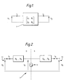
- Figure 1 is a diagram illustrating a two port network;
- Figure 2 is a schematic diagram of a power transmission line having a fault;
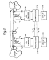
- Figure 3 is a schematic diagram of the equipment; and
- Figure 4 is a block schematic diagram showing the part of the equipment at one end of the transmission line in greater detail.
- The invention makes use of the well known two port network equation. The two port network equation relates the voltage and current at one port of a two port network to the voltage and current at the other port, as follows:

where, as illustrated in Figure 1, V₁ and I₁ are the voltage and current respectively at one port of a twoport network 1, V₂ and I₂ are the voltage and current respectively at the other port of the twoport network 1, and A₁, A₂, B₁ and B₂ are the parameters, i.e. transfer functions, of the twoport network 1. Multiplying out the matricies of equation (1) gives:


- The invention resides in the application of the two port network equation to the or each phase of a power transmission line having a fault in respect of the parts of the line on either side of the fault. Thus, referring to Figure 2, application of equation (2) to
parts fault 9 produces an equation:

forpart 3, and produces an equation:

forpart 5; where: Vf is the fault voltage; VS and IS are the voltage and current respectively at theend 11 of thepart 3 of the transmisson line 7 remote from thefault 9; VR and IR are the voltage and current respectively at theend 13 of thepart 5 of the transmission line 7 remote from thefault 9; AS and BS are first and second transmission line parameters between thefault 9 and theend 11; and AR and BR are first and second transmission line parameters between thefault 9 and thesecond end 13. From transmission line theory:


where T is the propagation constant of the line 7, x is the distance of thefault 9 along the transmission line 7 from theend 11, ZO is the characteristic impedance of the line 7 and L is the total length of the line 7 between theends - Equating the right-hand sides of equations (4) and (5) and substituting for AS, BS, AR and BR from equations (6) gives:

Expanding cosh (T(L-x)) and sinh (T(L-x)) gives:

Rearranging gives:

Therefore:
Therefore:
where:

and:

Hence, if the values of VS, IS, VR, IR, ZO, T and L are known, the distance x of thefault 9 along the transmission line 7 from theend 11 can be calculated from equations (7), (8) and (9). VS, IS, VR and IR can be measured at each end of the line and ZO,T and L will be known for a given transmission line. - It is to be noted that equations (7), (8) and (9) hold irrespective of the type of the
fault 9 and are indeterminate for a fault free healthy line. Furthermore, equations (7), (8) and (9) are independent of the fault path which may therefore be non-linear and still not affect the calculation of x. T and ZO cater for the non-transposition and shunt capacitance of the line and are not affected by the parameters of the network in which the transmission line is connected. - One example of an equipment for carrying out the method according to the invention will now be described with reference to Figure 3.
- The equipment comprises, at each of the two ends 11 and 13 of the line 7, a
voltage sensor current sensor end converter current sensors microprocessor display microprocessors microprocessor - Where the line 7 is a multiphase transmission line, the calculations are performed in respect of each phase of the transmitted power. However, in the case of a multiphase line the problem arises that the different phases will normally not be decoupled.
- To overcome this problem a modal component transformation may be used, as described in an article by L.M.Wedephol entitled 'Application of matrix methods to the solution of travelling-wave phenomena in polyphase systems' published in December 1963 in Proc. IEE, Vol 110, No 12, at pages 2200 to 2212.
- To this end the
microprocessors

and

where ASn, BSn, ARn and BRn are the model line parameters and


where Tn are the modal propagation constants of the line and ZOn are the characteristic modal impedances of the line. Equations (10), (11) and (12) are then worked in the same way as equations (4), (5) and (6) above to obtain the distance x of the fault along the line 7 from theend 11, as in equations (7), (8) and (9) above; that is:
where:

and

- One particular form of the equipment at each end of the line 7 will now be described in greater detail with reference to Figure 4. The equipment is for use with a three-phase transmission line. The three phase voltage and current signals Va, Vb, Vc, Ia, Ib and Ic from line transformers (not shown) are fed, via an
isolation transformer 33 andfilters 35 for extracting the power frequency phase information, to amultiplexer 37. The output of themultiplexer 37 is then passed via a sample and holdgate 39 to an A/D converter 41. The resultant digitised signals are stored in a cyclic buffer in arandom access memory 43 of amicroprocessor 44 by a directmemory access unit 45. An input/output unit 46 is sampled continuously until a start signal indicating occurrence of fault is received from a line protection equipment, typically a distance relay, after which the process of sampling the phase voltage and current signals Va, Vb, Vc, Ia, Ib, Ic continues until post fault data has been captured. Themicroprocessor 44 then carries out the necessary calculations. A keypad and alphanumeric display 47 are used to display and transfer the modal voltages and currents, to display the final distance to fault result calculated by the microprocessor and to enter the line parameters for storage in an electrically erasable programmable read onlymemory 49. - It will be understood that if the line 7 is a multi-circuit line there will be a set of modal components for each phase and each circuit. Thus for a single circuit three-phase line n will have
values values 1 to 6. - It will be further understood that transformations other than a modal component transformation may be used for decoupling purposes in equipment and methods according to the invention. For example, the well known symmetrical component transformation might be used, for example, if the transmission line conductors were known to be ideally transposed.
- It is also pointed out that whilst in the above explanation of the invention and in the equipment and method described by way of example, use of the voltage equation (2) is described, the current equation (3) could equally well be used.
Claims (10)
- An equipment for locating the position of a fault (9) on a power transmission line (7) between a first (11) and a second (13) end of said line (7) comprising: first means (15A,17A,19A) for deriving first and second signals representative respectively of the voltage VS and current IS at said first end (11); second means (15B,17B,19B) for deriving third and fourth signals representative respectively of the voltage VR and current IR at said second end (13); and means (21A,21B) for calculating the position of the fault (9) utilising said first, second, third and fourth signals and equations of the form:


where Xf is the fault voltage or current, AS is a first transmission parameter of the line (7) between the fault (9) and said first end (11), BS is a second transmission parameter of the line (7) between the fault (9) and said first end (11), AR is a first transmission parameter of the line (7) between the fault (9) and said second end (13), and BR is a second transmission parameter of the line (7) between the fault (9) and said second end (13), each said transmission parameter being dependent upon the distance of the fault (9) along the transmission line (7) from a said end (11 or 13) of the line (7). - An equipment according to Claim 1 wherein: Xf is the voltage at the fault (9);


- An equipment according to Claim 1 or Claim 2 wherein: said power transmission line (7) is a multi-phase power transmission line (7); said first (15A,17A,19A) and second (15B,17B,19B) means derive a set of said first, second, third and fourth signals in respect of each phase of said transmission line (7); and said means (21A,21B) for calculating includes means for transforming said signals to produce corresponding sets of decoupled signals VSn, ISn, VRn, IRn and means for utilising each set of said decoupled signals and equations of the form:


where n indicates the relevant said set. - An equipment according to Claim 3 wherein the transformation applied by said means for transforming is a modal component transformation.
- An equipment according to any one of the preceding claims wherein said first (15A,17A,19A) and second (15B,17B,19B) means each include an analogue to digital converter (19A,19B) and said means for calculating (21A,21B) comprises a microprocessor (21A,21B).
- A method of locating the position of a fault (9) on a power transmission line (7) between a first (11) and a second (13) end of said line (7) comprising the steps of: deriving first and second signals representative respectively of the voltage VS and current IS at said first end (11); deriving third and fourth signals representative respectively of the voltage VR and current IR at said second end (13); and calculating the position of the fault utilising said first, second, third and fourth signals and equations of the form:


where Xf is the fault voltage or current, AS is a first transmission parameter of the line (7) between the fault (9) and said first end (11), BS is a second transmission parameter of the line (7) between the fault (9) and said first end (11), AR is a first transmission parameter of the line (7) between the fault (9) and said second end (13), and BR is a second transmission parameter of the line (7) between the fault (9) and said second end (13), each said transmission parameter being dependent upon the distance of the fault (9) along the transmission line (7) from a said end (11 or 13) of the line (7). - A method according to Claim 6 wherein: Xf is the voltage at the fault (9);


- A method according to Claim 6 or Claim 7 wherein: said power transmission line (7) is a multi-phase power transmission line (7); the steps of deriving said first, second, third and fourth signals comprise deriving a set of said first, second, third and fourth signals in respect of each phase of said transmisssion line (7); and the step of calculating includes transforming said signals to produce corresponding sets of decoupled signals VSn, ISn, VRn, IRn and utilising each set of said decoupled signals and equations of the form:


where, n indicates the relevant set. - A method according to Claim 8 wherein the transformation applied in the step of transforming is the modal component transformation.
- A method according to any one of Claims 6 to 9 wherein said first, second, third and fourth signals are of digital form.
Applications Claiming Priority (2)
| Application Number | Priority Date | Filing Date | Title |
|---|---|---|---|
| GB8821204 | 1988-09-09 | ||
| GB8821204A GB2222688B (en) | 1988-09-09 | 1988-09-09 | Equipment for and methods of locating the position of a fault on a power transmission line |
Publications (3)
| Publication Number | Publication Date |
|---|---|
| EP0358488A2 EP0358488A2 (en) | 1990-03-14 |
| EP0358488A3 EP0358488A3 (en) | 1991-03-20 |
| EP0358488B1 true EP0358488B1 (en) | 1994-06-29 |
Family
ID=10643343
Family Applications (1)
| Application Number | Title | Priority Date | Filing Date |
|---|---|---|---|
| EP89309034A Expired - Lifetime EP0358488B1 (en) | 1988-09-09 | 1989-09-06 | Equipment for and methods of locating the position of a fault on a power transmission line |
Country Status (8)
| Country | Link |
|---|---|
| US (1) | US5072403A (en) |
| EP (1) | EP0358488B1 (en) |
| AU (1) | AU618843B2 (en) |
| CA (1) | CA1325826C (en) |
| DE (1) | DE68916495T2 (en) |
| GB (1) | GB2222688B (en) |
| IN (1) | IN176145B (en) |
| ZA (1) | ZA896838B (en) |
Cited By (1)
| Publication number | Priority date | Publication date | Assignee | Title |
|---|---|---|---|---|
| US7298149B2 (en) | 2002-06-20 | 2007-11-20 | Abb A.B. | Fault location using measurements of current and voltage from one end of a line |
Families Citing this family (37)
| Publication number | Priority date | Publication date | Assignee | Title |
|---|---|---|---|---|
| DE69115562T2 (en) * | 1990-05-31 | 1996-05-02 | Nissin Electric Co Ltd | Fault localization method of parallel double transmission lines with N outputs |
| DE69114792T2 (en) * | 1990-09-04 | 1996-04-18 | Hewlett Packard Co | Method and device for evaluating the nodes in a computer network. |
| EP0474380B1 (en) * | 1990-09-04 | 1995-11-02 | Hewlett-Packard Company | Method and apparatus for monitoring a network |
| US5198805A (en) * | 1990-09-04 | 1993-03-30 | Hewlett-Packard Company | Method and apparatus for monitoring a network and locating a node using signal strength calculations |
| GB2270217B (en) * | 1992-08-27 | 1996-04-10 | Univ Bath | Detecing faults in power lines |
| US5428549A (en) * | 1993-05-28 | 1995-06-27 | Abb Power T&D Company | Transmission line fault location system |
| US5453903A (en) * | 1993-08-18 | 1995-09-26 | Abb Power T&D Company, Inc. | Sub-cycle digital distance relay |
| US5455776A (en) * | 1993-09-08 | 1995-10-03 | Abb Power T & D Company Inc. | Automatic fault location system |
| JP3686430B2 (en) * | 1993-10-19 | 2005-08-24 | 東北電力株式会社 | Transmission line surge identification and orientation system |
| WO1995024014A2 (en) * | 1994-02-28 | 1995-09-08 | Abb Power T & D Company Inc. | One-terminal data fault location system |
| GB2288930B (en) * | 1994-04-25 | 1998-01-21 | Gec Alsthom Ltd | Methods and apparatus for identifying faulted phases on an electric power transmission line |
| DE4441334C1 (en) * | 1994-11-08 | 1996-07-11 | Siemens Ag | Method for determining the location of a fault in a predetermined monitoring area of a multi-phase electrical power transmission line system |
| SE515388C2 (en) * | 1995-09-14 | 2001-07-23 | Abb Research Ltd | Device for sensing electrical discharges in a sample object |
| DE19605022A1 (en) | 1996-01-31 | 1997-08-07 | Siemens Ag | Method for detecting an error on a line section to be monitored of an electrical transmission line according to the distance protection principle |
| DE19609595A1 (en) * | 1996-03-12 | 1997-10-23 | Aeg Energietechnik Gmbh | Method for determining equipment parameters for at least one distance protection device |
| US5798932A (en) * | 1996-05-21 | 1998-08-25 | General Electric Company | Methods and apparatus for removing error due to decaying offsets from measured power system currents |
| SE507043C2 (en) * | 1996-08-29 | 1998-03-16 | Asea Brown Boveri | Measurement procedure at line error locator on HVDC lines |
| US5839093A (en) * | 1996-12-31 | 1998-11-17 | Abb Transmit Oy | System for locating faults and estimating fault resistance in distribution networks with tapped loads |
| EP0933643A1 (en) * | 1998-02-02 | 1999-08-04 | Trench Austria GmbH | Procedure for fault localisation in AC networks |
| US6415244B1 (en) | 1998-03-31 | 2002-07-02 | Mehta Tech, Inc. | Power monitoring system and method |
| US6336059B1 (en) * | 1998-11-17 | 2002-01-01 | Abb Power T&D Company Inc. | Reach-measurement method for distance relays and fault locators on series-compensated transmission lines using local information |
| GB2345810B (en) * | 1999-01-13 | 2003-07-23 | Alstom Uk Ltd | Fault-detection apparatus |
| US6476613B2 (en) * | 2000-12-20 | 2002-11-05 | Abb Ab | Method of fault location in parallel transmission lines with series compensation |
| US6466030B2 (en) | 2000-12-29 | 2002-10-15 | Abb Power Automation Ltd. | Systems and methods for locating faults on a transmission line with a single tapped load |
| US6466031B1 (en) | 2000-12-29 | 2002-10-15 | Abb Power Automation Ltd. | Systems and methods for locating faults on a transmission line with multiple tapped loads |
| US7031859B2 (en) * | 2002-03-11 | 2006-04-18 | Piesinger Gregory H | Apparatus and method for identifying cable phase in a three-phase power distribution network |
| US6642700B2 (en) | 2002-03-26 | 2003-11-04 | Avistar, Inc. | System, method, field unit, reference unit and computer program product for phase tracking of electrical conductors |
| US6879917B2 (en) | 2002-06-14 | 2005-04-12 | Progress Energy Carolinas Inc. | Double-ended distance-to-fault location system using time-synchronized positive-or negative-sequence quantities |
| US6988042B2 (en) * | 2003-11-25 | 2006-01-17 | Myongji University | Method for detecting line-to-line fault location in power network |
| US20070063664A1 (en) * | 2005-09-22 | 2007-03-22 | Avistar, Inc. | Phase identification apparatus having automatic gain control to prevent detector saturation |
| EP2122795A1 (en) * | 2007-02-20 | 2009-11-25 | ABB Technology AG | Device and method for detecting faulted phases in a multi-phase electrical network |
| EP2223403B1 (en) * | 2007-12-14 | 2017-08-23 | ABB Schweiz AG | Fault direction determination |
| US8340931B2 (en) * | 2009-10-05 | 2012-12-25 | Mehta Tech, Inc. | Power grid with comparison of differences in remote phasor changes |
| RU2479903C1 (en) * | 2012-02-08 | 2013-04-20 | Общество с ограниченной ответственностью "АТЛАНТ" | Device to monitor and control signals of relay protection and emergency automation |
| RU2570572C1 (en) * | 2014-10-15 | 2015-12-10 | Общество с ограниченной ответственностью "АББ" | Microprocessor control panel |
| EP3171185B1 (en) | 2015-11-20 | 2018-06-27 | Siemens Aktiengesellschaft | Method and device for determining the fault location in the event of a fault on an electric line |
| CN110082636B (en) * | 2019-05-07 | 2021-02-26 | 哈尔滨理工大学 | Power cable fault positioning method and system |
Family Cites Families (16)
| Publication number | Priority date | Publication date | Assignee | Title |
|---|---|---|---|---|
| JPS52100149A (en) * | 1976-02-18 | 1977-08-22 | Tokyo Electric Power Co Inc:The | Digital failure point evaluating unit |
| JPS52154053A (en) * | 1976-06-18 | 1977-12-21 | Tokyo Electric Power Co Inc:The | System for locating fault point |
| US4371908A (en) * | 1979-09-17 | 1983-02-01 | Tokyo Shibaura Denki Kabushiki Kaisha | Digital protective relaying systems |
| IN155620B (en) * | 1980-03-01 | 1985-02-16 | Gen Electric Co Plc | |
| US4455612A (en) * | 1982-01-27 | 1984-06-19 | Iowa State University Research Foundation, Inc. | Recursive estimation in digital distance relaying system |
| SE433405B (en) * | 1982-09-14 | 1984-05-21 | Asea Ab | PROCEDURE AND DEVICE FOR LOCATING A FAILURE ON A THREE-PHASE POWER CORD |
| US4570231A (en) * | 1984-01-27 | 1986-02-11 | Richard H. Bunch | Fault finder |
| US4766549A (en) * | 1984-11-30 | 1988-08-23 | Electric Power Research Institute, Inc. | Single-ended transmission line fault locator |
| JPH0812222B2 (en) * | 1985-11-08 | 1996-02-07 | 株式会社東芝 | Digital fault locator |
| SE449796B (en) * | 1985-12-20 | 1987-05-18 | Asea Ab | PROCEDURE AND DEVICE FOR LOCATION OF ERRORS ON A POWER CORD |
| FR2592492B1 (en) * | 1985-12-30 | 1988-04-01 | Enertec | METHOD FOR LOCATING A FAULT ON A POWER LINE |
| AU582039B2 (en) * | 1986-03-07 | 1989-03-09 | Mitsubishi Denki Kabushiki Kaisha | Fault point locating method, fault point resistance measuring method, and impendance to fault point measuring method and apparatuses therefor |
| DE3764009D1 (en) * | 1986-04-14 | 1990-09-06 | Siemens Ag | METHOD AND DEVICES FOR DETECTING AND LOCALIZING DAMAGE IN ELECTRICAL SYSTEMS. |
| JPH0758305B2 (en) * | 1986-04-22 | 1995-06-21 | 中部電力株式会社 | Fault location method |
| US4812995A (en) * | 1987-05-19 | 1989-03-14 | Girgis Adly A | Adaptive Kalman Filtering in fault classification |
| US4795983A (en) * | 1988-03-07 | 1989-01-03 | Westinghouse Electric Corp. | Method and apparatus for identifying a faulted phase |
-
1988
- 1988-09-09 GB GB8821204A patent/GB2222688B/en not_active Expired - Lifetime
-
1989
- 1989-09-05 IN IN786DE1989 patent/IN176145B/en unknown
- 1989-09-06 DE DE68916495T patent/DE68916495T2/en not_active Expired - Fee Related
- 1989-09-06 EP EP89309034A patent/EP0358488B1/en not_active Expired - Lifetime
- 1989-09-06 US US07/403,377 patent/US5072403A/en not_active Expired - Lifetime
- 1989-09-07 AU AU41142/89A patent/AU618843B2/en not_active Ceased
- 1989-09-07 ZA ZA896838A patent/ZA896838B/en unknown
- 1989-09-08 CA CA000610700A patent/CA1325826C/en not_active Expired - Fee Related
Cited By (1)
| Publication number | Priority date | Publication date | Assignee | Title |
|---|---|---|---|---|
| US7298149B2 (en) | 2002-06-20 | 2007-11-20 | Abb A.B. | Fault location using measurements of current and voltage from one end of a line |
Also Published As
| Publication number | Publication date |
|---|---|
| DE68916495D1 (en) | 1994-08-04 |
| ZA896838B (en) | 1990-05-30 |
| GB8821204D0 (en) | 1988-10-12 |
| IN176145B (en) | 1996-02-10 |
| GB2222688B (en) | 1992-12-23 |
| GB2222688A (en) | 1990-03-14 |
| DE68916495T2 (en) | 1994-10-13 |
| US5072403A (en) | 1991-12-10 |
| AU618843B2 (en) | 1992-01-09 |
| CA1325826C (en) | 1994-01-04 |
| EP0358488A3 (en) | 1991-03-20 |
| AU4114289A (en) | 1990-03-15 |
| EP0358488A2 (en) | 1990-03-14 |
Similar Documents
| Publication | Publication Date | Title |
|---|---|---|
| EP0358488B1 (en) | Equipment for and methods of locating the position of a fault on a power transmission line | |
| AU618844B2 (en) | Arrangement for operating a multi-component mixing capsule, in particular for dental purposes, by means of a vibratory mixing device | |
| US4148087A (en) | Distance relay for electric power transmission lines | |
| US5446387A (en) | Method and a device for determining a fault on a transmission line | |
| US4276605A (en) | Method and apparatus for supervising a digital protective relaying system | |
| US4996624A (en) | Fault location method for radial transmission and distribution systems | |
| US3590368A (en) | Detection of faults a power transmission line | |
| EP0459522A2 (en) | Fault location method for a parallel two-circuit transmission line with N terminals | |
| US5608327A (en) | Methods and apparatus for identifying faulted phases on an electric power transmission line | |
| US6420876B1 (en) | Fault location in a medium-voltage network | |
| EP0139123B1 (en) | Protective relay system | |
| US4689709A (en) | Digital distance relay | |
| EP1311866B1 (en) | Current compensation method and device for power system protection | |
| US6336059B1 (en) | Reach-measurement method for distance relays and fault locators on series-compensated transmission lines using local information | |
| KR100232764B1 (en) | Apparatus and method for measuring impedance of a digital distance relay | |
| Sidhu et al. | Detecting transformer winding faults using non-linear models of transformers | |
| US6584365B1 (en) | Electronic trip device with offset correction means | |
| Miki et al. | Study of high-speed distance relay using microcomputer | |
| Humpage et al. | Dynamic simulation of high-speed protection | |
| JPS5857059B2 (en) | Distribution line short circuit protection method | |
| JP3457408B2 (en) | Accident section judgment device | |
| JP2953891B2 (en) | Digital bus protection device | |
| GB2210218A (en) | Fault locator in an electrical power transmission system | |
| JP2001045666A (en) | Individual operation detector for distributed electric power source | |
| JP2795128B2 (en) | Ground fault distance relay |
Legal Events
| Date | Code | Title | Description |
|---|---|---|---|
| PUAI | Public reference made under article 153(3) epc to a published international application that has entered the european phase |
Free format text: ORIGINAL CODE: 0009012 |
|
| AK | Designated contracting states |
Kind code of ref document: A2 Designated state(s): CH DE FR LI SE |
|
| PUAL | Search report despatched |
Free format text: ORIGINAL CODE: 0009013 |
|
| AK | Designated contracting states |
Kind code of ref document: A3 Designated state(s): CH DE FR LI SE |
|
| 17P | Request for examination filed |
Effective date: 19910830 |
|
| 17Q | First examination report despatched |
Effective date: 19921124 |
|
| GRAA | (expected) grant |
Free format text: ORIGINAL CODE: 0009210 |
|
| AK | Designated contracting states |
Kind code of ref document: B1 Designated state(s): CH DE FR LI SE |
|
| ET | Fr: translation filed | ||
| REF | Corresponds to: |
Ref document number: 68916495 Country of ref document: DE Date of ref document: 19940804 |
|
| EAL | Se: european patent in force in sweden |
Ref document number: 89309034.0 |
|
| PLBE | No opposition filed within time limit |
Free format text: ORIGINAL CODE: 0009261 |
|
| STAA | Information on the status of an ep patent application or granted ep patent |
Free format text: STATUS: NO OPPOSITION FILED WITHIN TIME LIMIT |
|
| 26N | No opposition filed | ||
| REG | Reference to a national code |
Ref country code: CH Ref legal event code: PCAR Free format text: JOHN P. MUNZINGER C/O CRONIN INTELLECTUAL PROPERTY;CHEMIN DE PRECOSSY 31;1260 NYON (CH) |
|
| REG | Reference to a national code |
Ref country code: FR Ref legal event code: CA Ref country code: FR Ref legal event code: CD |
|
| PGFP | Annual fee paid to national office [announced via postgrant information from national office to epo] |
Ref country code: CH Payment date: 20070927 Year of fee payment: 19 |
|
| PGFP | Annual fee paid to national office [announced via postgrant information from national office to epo] |
Ref country code: SE Payment date: 20070905 Year of fee payment: 19 Ref country code: DE Payment date: 20070929 Year of fee payment: 19 |
|
| REG | Reference to a national code |
Ref country code: FR Ref legal event code: TP |
|
| PGFP | Annual fee paid to national office [announced via postgrant information from national office to epo] |
Ref country code: FR Payment date: 20070927 Year of fee payment: 19 |
|
| REG | Reference to a national code |
Ref country code: CH Ref legal event code: PL |
|
| REG | Reference to a national code |
Ref country code: FR Ref legal event code: ST Effective date: 20090529 |
|
| PG25 | Lapsed in a contracting state [announced via postgrant information from national office to epo] |
Ref country code: DE Free format text: LAPSE BECAUSE OF NON-PAYMENT OF DUE FEES Effective date: 20090401 |
|
| PG25 | Lapsed in a contracting state [announced via postgrant information from national office to epo] |
Ref country code: CH Free format text: LAPSE BECAUSE OF NON-PAYMENT OF DUE FEES Effective date: 20080930 Ref country code: LI Free format text: LAPSE BECAUSE OF NON-PAYMENT OF DUE FEES Effective date: 20080930 Ref country code: FR Free format text: LAPSE BECAUSE OF NON-PAYMENT OF DUE FEES Effective date: 20080930 |
|
| PG25 | Lapsed in a contracting state [announced via postgrant information from national office to epo] |
Ref country code: SE Free format text: LAPSE BECAUSE OF NON-PAYMENT OF DUE FEES Effective date: 20080907 |