EP0360139A2 - Ostheosynthesis device and manufacturing process - Google Patents
Ostheosynthesis device and manufacturing process Download PDFInfo
- Publication number
- EP0360139A2 EP0360139A2 EP89116920A EP89116920A EP0360139A2 EP 0360139 A2 EP0360139 A2 EP 0360139A2 EP 89116920 A EP89116920 A EP 89116920A EP 89116920 A EP89116920 A EP 89116920A EP 0360139 A2 EP0360139 A2 EP 0360139A2
- Authority
- EP
- European Patent Office
- Prior art keywords
- osteosynthesis
- resorbable
- plate
- threaded rod
- resorbable device
- Prior art date
- Legal status (The legal status is an assumption and is not a legal conclusion. Google has not performed a legal analysis and makes no representation as to the accuracy of the status listed.)
- Withdrawn
Links
- 238000004519 manufacturing process Methods 0.000 title claims abstract description 13
- 210000000988 bone and bone Anatomy 0.000 claims description 38
- 229920000642 polymer Polymers 0.000 claims description 26
- 239000008187 granular material Substances 0.000 claims description 25
- 239000000463 material Substances 0.000 claims description 17
- 229910000389 calcium phosphate Inorganic materials 0.000 claims description 15
- 239000001506 calcium phosphate Substances 0.000 claims description 15
- 235000011010 calcium phosphates Nutrition 0.000 claims description 15
- QORWJWZARLRLPR-UHFFFAOYSA-H tricalcium bis(phosphate) Chemical compound [Ca+2].[Ca+2].[Ca+2].[O-]P([O-])([O-])=O.[O-]P([O-])([O-])=O QORWJWZARLRLPR-UHFFFAOYSA-H 0.000 claims description 15
- 239000002245 particle Substances 0.000 claims description 14
- 229910052588 hydroxylapatite Inorganic materials 0.000 claims description 11
- XYJRXVWERLGGKC-UHFFFAOYSA-D pentacalcium;hydroxide;triphosphate Chemical compound [OH-].[Ca+2].[Ca+2].[Ca+2].[Ca+2].[Ca+2].[O-]P([O-])([O-])=O.[O-]P([O-])([O-])=O.[O-]P([O-])([O-])=O XYJRXVWERLGGKC-UHFFFAOYSA-D 0.000 claims description 11
- 239000011248 coating agent Substances 0.000 claims description 10
- 238000000576 coating method Methods 0.000 claims description 10
- JJTUDXZGHPGLLC-IMJSIDKUSA-N 4511-42-6 Chemical compound C[C@@H]1OC(=O)[C@H](C)OC1=O JJTUDXZGHPGLLC-IMJSIDKUSA-N 0.000 claims description 7
- 229920001577 copolymer Polymers 0.000 claims description 7
- 229910052709 silver Inorganic materials 0.000 claims description 7
- 239000004332 silver Substances 0.000 claims description 7
- 230000002787 reinforcement Effects 0.000 claims description 5
- 230000008719 thickening Effects 0.000 claims description 5
- 238000010438 heat treatment Methods 0.000 claims description 3
- 229920001432 poly(L-lactide) Polymers 0.000 claims description 3
- AEMRFAOFKBGASW-UHFFFAOYSA-N Glycolic acid Polymers OCC(O)=O AEMRFAOFKBGASW-UHFFFAOYSA-N 0.000 claims description 2
- 229920000954 Polyglycolide Polymers 0.000 claims description 2
- 230000003385 bacteriostatic effect Effects 0.000 claims description 2
- 239000011149 active material Substances 0.000 claims 1
- 239000003899 bactericide agent Substances 0.000 claims 1
- 239000000022 bacteriostatic agent Substances 0.000 claims 1
- 230000003247 decreasing effect Effects 0.000 claims 1
- 239000012783 reinforcing fiber Substances 0.000 claims 1
- 239000007943 implant Substances 0.000 description 12
- 239000000835 fiber Substances 0.000 description 10
- 229910052751 metal Inorganic materials 0.000 description 9
- 239000002184 metal Substances 0.000 description 9
- 238000001746 injection moulding Methods 0.000 description 8
- 206010017076 Fracture Diseases 0.000 description 7
- BQCADISMDOOEFD-UHFFFAOYSA-N Silver Chemical compound [Ag] BQCADISMDOOEFD-UHFFFAOYSA-N 0.000 description 7
- 239000004068 calcium phosphate ceramic Substances 0.000 description 7
- 229920000747 poly(lactic acid) Polymers 0.000 description 7
- 208000010392 Bone Fractures Diseases 0.000 description 6
- 238000010521 absorption reaction Methods 0.000 description 6
- 238000013461 design Methods 0.000 description 6
- 239000012634 fragment Substances 0.000 description 6
- 230000008901 benefit Effects 0.000 description 5
- 230000005540 biological transmission Effects 0.000 description 5
- 238000000034 method Methods 0.000 description 5
- 230000000844 anti-bacterial effect Effects 0.000 description 4
- 229920003023 plastic Polymers 0.000 description 4
- 239000004033 plastic Substances 0.000 description 4
- 210000001519 tissue Anatomy 0.000 description 4
- 239000003242 anti bacterial agent Substances 0.000 description 3
- 229940088710 antibiotic agent Drugs 0.000 description 3
- 230000015556 catabolic process Effects 0.000 description 3
- 238000006731 degradation reaction Methods 0.000 description 3
- 230000000694 effects Effects 0.000 description 3
- 230000035876 healing Effects 0.000 description 3
- 230000001988 toxicity Effects 0.000 description 3
- 231100000419 toxicity Toxicity 0.000 description 3
- 238000012800 visualization Methods 0.000 description 3
- CPKVUHPKYQGHMW-UHFFFAOYSA-N 1-ethenylpyrrolidin-2-one;molecular iodine Chemical compound II.C=CN1CCCC1=O CPKVUHPKYQGHMW-UHFFFAOYSA-N 0.000 description 2
- 229940126575 aminoglycoside Drugs 0.000 description 2
- 210000003423 ankle Anatomy 0.000 description 2
- 238000013459 approach Methods 0.000 description 2
- 238000005452 bending Methods 0.000 description 2
- 239000002131 composite material Substances 0.000 description 2
- 238000005553 drilling Methods 0.000 description 2
- 239000002657 fibrous material Substances 0.000 description 2
- 239000002271 gyrase inhibitor Substances 0.000 description 2
- 230000006872 improvement Effects 0.000 description 2
- 239000002861 polymer material Substances 0.000 description 2
- 239000000843 powder Substances 0.000 description 2
- 230000036316 preload Effects 0.000 description 2
- 230000002028 premature Effects 0.000 description 2
- 230000008569 process Effects 0.000 description 2
- 238000012545 processing Methods 0.000 description 2
- 230000006641 stabilisation Effects 0.000 description 2
- 238000011105 stabilization Methods 0.000 description 2
- 230000003313 weakening effect Effects 0.000 description 2
- 238000003466 welding Methods 0.000 description 2
- RKDVKSZUMVYZHH-UHFFFAOYSA-N 1,4-dioxane-2,5-dione Chemical compound O=C1COC(=O)CO1 RKDVKSZUMVYZHH-UHFFFAOYSA-N 0.000 description 1
- ZCYVEMRRCGMTRW-UHFFFAOYSA-N 7553-56-2 Chemical compound [I] ZCYVEMRRCGMTRW-UHFFFAOYSA-N 0.000 description 1
- 206010065687 Bone loss Diseases 0.000 description 1
- LFQSCWFLJHTTHZ-UHFFFAOYSA-N Ethanol Chemical compound CCO LFQSCWFLJHTTHZ-UHFFFAOYSA-N 0.000 description 1
- 206010020751 Hypersensitivity Diseases 0.000 description 1
- 241001465754 Metazoa Species 0.000 description 1
- 229910000990 Ni alloy Inorganic materials 0.000 description 1
- 229920000153 Povidone-iodine Polymers 0.000 description 1
- 244000063498 Spondias mombin Species 0.000 description 1
- 235000015127 Spondias tuberosa Nutrition 0.000 description 1
- 108010059993 Vancomycin Proteins 0.000 description 1
- 208000027418 Wounds and injury Diseases 0.000 description 1
- 230000001154 acute effect Effects 0.000 description 1
- 230000007815 allergy Effects 0.000 description 1
- 230000003115 biocidal effect Effects 0.000 description 1
- 238000010276 construction Methods 0.000 description 1
- 238000004132 cross linking Methods 0.000 description 1
- 238000005520 cutting process Methods 0.000 description 1
- 239000007857 degradation product Substances 0.000 description 1
- 238000011161 development Methods 0.000 description 1
- 238000007731 hot pressing Methods 0.000 description 1
- 238000002347 injection Methods 0.000 description 1
- 239000007924 injection Substances 0.000 description 1
- 229910052500 inorganic mineral Inorganic materials 0.000 description 1
- 238000001990 intravenous administration Methods 0.000 description 1
- 239000011630 iodine Substances 0.000 description 1
- 229910052740 iodine Inorganic materials 0.000 description 1
- 230000007794 irritation Effects 0.000 description 1
- 239000011159 matrix material Substances 0.000 description 1
- 238000005259 measurement Methods 0.000 description 1
- 230000007246 mechanism Effects 0.000 description 1
- 230000002503 metabolic effect Effects 0.000 description 1
- 239000011707 mineral Substances 0.000 description 1
- 239000000178 monomer Substances 0.000 description 1
- 229910052759 nickel Inorganic materials 0.000 description 1
- PXHVJJICTQNCMI-UHFFFAOYSA-N nickel Substances [Ni] PXHVJJICTQNCMI-UHFFFAOYSA-N 0.000 description 1
- 238000012856 packing Methods 0.000 description 1
- 230000004962 physiological condition Effects 0.000 description 1
- 238000002360 preparation method Methods 0.000 description 1
- 238000003825 pressing Methods 0.000 description 1
- 230000009467 reduction Effects 0.000 description 1
- 239000012779 reinforcing material Substances 0.000 description 1
- 210000002966 serum Anatomy 0.000 description 1
- 238000004904 shortening Methods 0.000 description 1
- FJOLTQXXWSRAIX-UHFFFAOYSA-K silver phosphate Chemical compound [Ag+].[Ag+].[Ag+].[O-]P([O-])([O-])=O FJOLTQXXWSRAIX-UHFFFAOYSA-K 0.000 description 1
- 229940019931 silver phosphate Drugs 0.000 description 1
- 229910000161 silver phosphate Inorganic materials 0.000 description 1
- 239000007787 solid Substances 0.000 description 1
- 239000000243 solution Substances 0.000 description 1
- 230000002269 spontaneous effect Effects 0.000 description 1
- 239000007921 spray Substances 0.000 description 1
- 238000005507 spraying Methods 0.000 description 1
- 229910001220 stainless steel Inorganic materials 0.000 description 1
- 238000003860 storage Methods 0.000 description 1
- 239000000126 substance Substances 0.000 description 1
- 238000001356 surgical procedure Methods 0.000 description 1
- 238000012360 testing method Methods 0.000 description 1
- 238000004154 testing of material Methods 0.000 description 1
- 229960003165 vancomycin Drugs 0.000 description 1
- MYPYJXKWCTUITO-LYRMYLQWSA-N vancomycin Chemical compound O([C@@H]1[C@@H](O)[C@H](O)[C@@H](CO)O[C@H]1OC1=C2C=C3C=C1OC1=CC=C(C=C1Cl)[C@@H](O)[C@H](C(N[C@@H](CC(N)=O)C(=O)N[C@H]3C(=O)N[C@H]1C(=O)N[C@H](C(N[C@@H](C3=CC(O)=CC(O)=C3C=3C(O)=CC=C1C=3)C(O)=O)=O)[C@H](O)C1=CC=C(C(=C1)Cl)O2)=O)NC(=O)[C@@H](CC(C)C)NC)[C@H]1C[C@](C)(N)[C@H](O)[C@H](C)O1 MYPYJXKWCTUITO-LYRMYLQWSA-N 0.000 description 1
- MYPYJXKWCTUITO-UHFFFAOYSA-N vancomycin Natural products O1C(C(=C2)Cl)=CC=C2C(O)C(C(NC(C2=CC(O)=CC(O)=C2C=2C(O)=CC=C3C=2)C(O)=O)=O)NC(=O)C3NC(=O)C2NC(=O)C(CC(N)=O)NC(=O)C(NC(=O)C(CC(C)C)NC)C(O)C(C=C3Cl)=CC=C3OC3=CC2=CC1=C3OC1OC(CO)C(O)C(O)C1OC1CC(C)(N)C(O)C(C)O1 MYPYJXKWCTUITO-UHFFFAOYSA-N 0.000 description 1
Images

Classifications
-
- A—HUMAN NECESSITIES
- A61—MEDICAL OR VETERINARY SCIENCE; HYGIENE
- A61B—DIAGNOSIS; SURGERY; IDENTIFICATION
- A61B17/00—Surgical instruments, devices or methods, e.g. tourniquets
- A61B17/56—Surgical instruments or methods for treatment of bones or joints; Devices specially adapted therefor
- A61B17/58—Surgical instruments or methods for treatment of bones or joints; Devices specially adapted therefor for osteosynthesis, e.g. bone plates, screws, setting implements or the like
- A61B17/68—Internal fixation devices, including fasteners and spinal fixators, even if a part thereof projects from the skin
- A61B17/80—Cortical plates, i.e. bone plates; Instruments for holding or positioning cortical plates, or for compressing bones attached to cortical plates
- A61B17/8033—Cortical plates, i.e. bone plates; Instruments for holding or positioning cortical plates, or for compressing bones attached to cortical plates having indirect contact with screw heads, or having contact with screw heads maintained with the aid of additional components, e.g. nuts, wedges or head covers
- A61B17/8047—Cortical plates, i.e. bone plates; Instruments for holding or positioning cortical plates, or for compressing bones attached to cortical plates having indirect contact with screw heads, or having contact with screw heads maintained with the aid of additional components, e.g. nuts, wedges or head covers wherein the additional element surrounds the screw head in the plate hole
-
- A—HUMAN NECESSITIES
- A61—MEDICAL OR VETERINARY SCIENCE; HYGIENE
- A61B—DIAGNOSIS; SURGERY; IDENTIFICATION
- A61B17/00—Surgical instruments, devices or methods, e.g. tourniquets
- A61B17/56—Surgical instruments or methods for treatment of bones or joints; Devices specially adapted therefor
- A61B17/58—Surgical instruments or methods for treatment of bones or joints; Devices specially adapted therefor for osteosynthesis, e.g. bone plates, screws, setting implements or the like
- A61B17/68—Internal fixation devices, including fasteners and spinal fixators, even if a part thereof projects from the skin
- A61B17/84—Fasteners therefor or fasteners being internal fixation devices
- A61B17/86—Pins or screws or threaded wires; nuts therefor
- A61B17/8605—Heads, i.e. proximal ends projecting from bone
-
- A—HUMAN NECESSITIES
- A61—MEDICAL OR VETERINARY SCIENCE; HYGIENE
- A61B—DIAGNOSIS; SURGERY; IDENTIFICATION
- A61B17/00—Surgical instruments, devices or methods, e.g. tourniquets
- A61B17/56—Surgical instruments or methods for treatment of bones or joints; Devices specially adapted therefor
- A61B17/58—Surgical instruments or methods for treatment of bones or joints; Devices specially adapted therefor for osteosynthesis, e.g. bone plates, screws, setting implements or the like
- A61B17/68—Internal fixation devices, including fasteners and spinal fixators, even if a part thereof projects from the skin
- A61B17/84—Fasteners therefor or fasteners being internal fixation devices
- A61B17/86—Pins or screws or threaded wires; nuts therefor
- A61B17/866—Material or manufacture
-
- A—HUMAN NECESSITIES
- A61—MEDICAL OR VETERINARY SCIENCE; HYGIENE
- A61L—METHODS OR APPARATUS FOR STERILISING MATERIALS OR OBJECTS IN GENERAL; DISINFECTION, STERILISATION OR DEODORISATION OF AIR; CHEMICAL ASPECTS OF BANDAGES, DRESSINGS, ABSORBENT PADS OR SURGICAL ARTICLES; MATERIALS FOR BANDAGES, DRESSINGS, ABSORBENT PADS OR SURGICAL ARTICLES
- A61L31/00—Materials for other surgical articles, e.g. stents, stent-grafts, shunts, surgical drapes, guide wires, materials for adhesion prevention, occluding devices, surgical gloves, tissue fixation devices
- A61L31/04—Macromolecular materials
- A61L31/06—Macromolecular materials obtained otherwise than by reactions only involving carbon-to-carbon unsaturated bonds
-
- A—HUMAN NECESSITIES
- A61—MEDICAL OR VETERINARY SCIENCE; HYGIENE
- A61L—METHODS OR APPARATUS FOR STERILISING MATERIALS OR OBJECTS IN GENERAL; DISINFECTION, STERILISATION OR DEODORISATION OF AIR; CHEMICAL ASPECTS OF BANDAGES, DRESSINGS, ABSORBENT PADS OR SURGICAL ARTICLES; MATERIALS FOR BANDAGES, DRESSINGS, ABSORBENT PADS OR SURGICAL ARTICLES
- A61L31/00—Materials for other surgical articles, e.g. stents, stent-grafts, shunts, surgical drapes, guide wires, materials for adhesion prevention, occluding devices, surgical gloves, tissue fixation devices
- A61L31/08—Materials for coatings
- A61L31/082—Inorganic materials
- A61L31/086—Phosphorus-containing materials, e.g. apatite
-
- A—HUMAN NECESSITIES
- A61—MEDICAL OR VETERINARY SCIENCE; HYGIENE
- A61L—METHODS OR APPARATUS FOR STERILISING MATERIALS OR OBJECTS IN GENERAL; DISINFECTION, STERILISATION OR DEODORISATION OF AIR; CHEMICAL ASPECTS OF BANDAGES, DRESSINGS, ABSORBENT PADS OR SURGICAL ARTICLES; MATERIALS FOR BANDAGES, DRESSINGS, ABSORBENT PADS OR SURGICAL ARTICLES
- A61L31/00—Materials for other surgical articles, e.g. stents, stent-grafts, shunts, surgical drapes, guide wires, materials for adhesion prevention, occluding devices, surgical gloves, tissue fixation devices
- A61L31/12—Composite materials, i.e. containing one material dispersed in a matrix of the same or different material
- A61L31/125—Composite materials, i.e. containing one material dispersed in a matrix of the same or different material having a macromolecular matrix
-
- A—HUMAN NECESSITIES
- A61—MEDICAL OR VETERINARY SCIENCE; HYGIENE
- A61L—METHODS OR APPARATUS FOR STERILISING MATERIALS OR OBJECTS IN GENERAL; DISINFECTION, STERILISATION OR DEODORISATION OF AIR; CHEMICAL ASPECTS OF BANDAGES, DRESSINGS, ABSORBENT PADS OR SURGICAL ARTICLES; MATERIALS FOR BANDAGES, DRESSINGS, ABSORBENT PADS OR SURGICAL ARTICLES
- A61L31/00—Materials for other surgical articles, e.g. stents, stent-grafts, shunts, surgical drapes, guide wires, materials for adhesion prevention, occluding devices, surgical gloves, tissue fixation devices
- A61L31/14—Materials characterised by their function or physical properties, e.g. injectable or lubricating compositions, shape-memory materials, surface modified materials
- A61L31/148—Materials at least partially resorbable by the body
-
- A—HUMAN NECESSITIES
- A61—MEDICAL OR VETERINARY SCIENCE; HYGIENE
- A61L—METHODS OR APPARATUS FOR STERILISING MATERIALS OR OBJECTS IN GENERAL; DISINFECTION, STERILISATION OR DEODORISATION OF AIR; CHEMICAL ASPECTS OF BANDAGES, DRESSINGS, ABSORBENT PADS OR SURGICAL ARTICLES; MATERIALS FOR BANDAGES, DRESSINGS, ABSORBENT PADS OR SURGICAL ARTICLES
- A61L31/00—Materials for other surgical articles, e.g. stents, stent-grafts, shunts, surgical drapes, guide wires, materials for adhesion prevention, occluding devices, surgical gloves, tissue fixation devices
- A61L31/14—Materials characterised by their function or physical properties, e.g. injectable or lubricating compositions, shape-memory materials, surface modified materials
- A61L31/16—Biologically active materials, e.g. therapeutic substances
-
- A—HUMAN NECESSITIES
- A61—MEDICAL OR VETERINARY SCIENCE; HYGIENE
- A61B—DIAGNOSIS; SURGERY; IDENTIFICATION
- A61B17/00—Surgical instruments, devices or methods, e.g. tourniquets
- A61B2017/00004—(bio)absorbable, (bio)resorbable, resorptive
-
- A—HUMAN NECESSITIES
- A61—MEDICAL OR VETERINARY SCIENCE; HYGIENE
- A61B—DIAGNOSIS; SURGERY; IDENTIFICATION
- A61B90/00—Instruments, implements or accessories specially adapted for surgery or diagnosis and not covered by any of the groups A61B1/00 - A61B50/00, e.g. for luxation treatment or for protecting wound edges
- A61B90/03—Automatic limiting or abutting means, e.g. for safety
- A61B2090/037—Automatic limiting or abutting means, e.g. for safety with a frangible part, e.g. by reduced diameter
-
- A—HUMAN NECESSITIES
- A61—MEDICAL OR VETERINARY SCIENCE; HYGIENE
- A61B—DIAGNOSIS; SURGERY; IDENTIFICATION
- A61B90/00—Instruments, implements or accessories specially adapted for surgery or diagnosis and not covered by any of the groups A61B1/00 - A61B50/00, e.g. for luxation treatment or for protecting wound edges
- A61B90/39—Markers, e.g. radio-opaque or breast lesions markers
-
- A—HUMAN NECESSITIES
- A61—MEDICAL OR VETERINARY SCIENCE; HYGIENE
- A61F—FILTERS IMPLANTABLE INTO BLOOD VESSELS; PROSTHESES; DEVICES PROVIDING PATENCY TO, OR PREVENTING COLLAPSING OF, TUBULAR STRUCTURES OF THE BODY, e.g. STENTS; ORTHOPAEDIC, NURSING OR CONTRACEPTIVE DEVICES; FOMENTATION; TREATMENT OR PROTECTION OF EYES OR EARS; BANDAGES, DRESSINGS OR ABSORBENT PADS; FIRST-AID KITS
- A61F2/00—Filters implantable into blood vessels; Prostheses, i.e. artificial substitutes or replacements for parts of the body; Appliances for connecting them with the body; Devices providing patency to, or preventing collapsing of, tubular structures of the body, e.g. stents
- A61F2/0077—Special surfaces of prostheses, e.g. for improving ingrowth
-
- A—HUMAN NECESSITIES
- A61—MEDICAL OR VETERINARY SCIENCE; HYGIENE
- A61F—FILTERS IMPLANTABLE INTO BLOOD VESSELS; PROSTHESES; DEVICES PROVIDING PATENCY TO, OR PREVENTING COLLAPSING OF, TUBULAR STRUCTURES OF THE BODY, e.g. STENTS; ORTHOPAEDIC, NURSING OR CONTRACEPTIVE DEVICES; FOMENTATION; TREATMENT OR PROTECTION OF EYES OR EARS; BANDAGES, DRESSINGS OR ABSORBENT PADS; FIRST-AID KITS
- A61F2310/00—Prostheses classified in A61F2/28 or A61F2/30 - A61F2/44 being constructed from or coated with a particular material
- A61F2310/00389—The prosthesis being coated or covered with a particular material
- A61F2310/00592—Coating or prosthesis-covering structure made of ceramics or of ceramic-like compounds
- A61F2310/00796—Coating or prosthesis-covering structure made of a phosphorus-containing compound, e.g. hydroxy(l)apatite
-
- A—HUMAN NECESSITIES
- A61—MEDICAL OR VETERINARY SCIENCE; HYGIENE
- A61L—METHODS OR APPARATUS FOR STERILISING MATERIALS OR OBJECTS IN GENERAL; DISINFECTION, STERILISATION OR DEODORISATION OF AIR; CHEMICAL ASPECTS OF BANDAGES, DRESSINGS, ABSORBENT PADS OR SURGICAL ARTICLES; MATERIALS FOR BANDAGES, DRESSINGS, ABSORBENT PADS OR SURGICAL ARTICLES
- A61L2300/00—Biologically active materials used in bandages, wound dressings, absorbent pads or medical devices
- A61L2300/10—Biologically active materials used in bandages, wound dressings, absorbent pads or medical devices containing or releasing inorganic materials
- A61L2300/102—Metals or metal compounds, e.g. salts such as bicarbonates, carbonates, oxides, zeolites, silicates
- A61L2300/104—Silver, e.g. silver sulfadiazine
-
- A—HUMAN NECESSITIES
- A61—MEDICAL OR VETERINARY SCIENCE; HYGIENE
- A61L—METHODS OR APPARATUS FOR STERILISING MATERIALS OR OBJECTS IN GENERAL; DISINFECTION, STERILISATION OR DEODORISATION OF AIR; CHEMICAL ASPECTS OF BANDAGES, DRESSINGS, ABSORBENT PADS OR SURGICAL ARTICLES; MATERIALS FOR BANDAGES, DRESSINGS, ABSORBENT PADS OR SURGICAL ARTICLES
- A61L2300/00—Biologically active materials used in bandages, wound dressings, absorbent pads or medical devices
- A61L2300/40—Biologically active materials used in bandages, wound dressings, absorbent pads or medical devices characterised by a specific therapeutic activity or mode of action
- A61L2300/404—Biocides, antimicrobial agents, antiseptic agents
-
- A—HUMAN NECESSITIES
- A61—MEDICAL OR VETERINARY SCIENCE; HYGIENE
- A61L—METHODS OR APPARATUS FOR STERILISING MATERIALS OR OBJECTS IN GENERAL; DISINFECTION, STERILISATION OR DEODORISATION OF AIR; CHEMICAL ASPECTS OF BANDAGES, DRESSINGS, ABSORBENT PADS OR SURGICAL ARTICLES; MATERIALS FOR BANDAGES, DRESSINGS, ABSORBENT PADS OR SURGICAL ARTICLES
- A61L2430/00—Materials or treatment for tissue regeneration
- A61L2430/02—Materials or treatment for tissue regeneration for reconstruction of bones; weight-bearing implants
-
- Y—GENERAL TAGGING OF NEW TECHNOLOGICAL DEVELOPMENTS; GENERAL TAGGING OF CROSS-SECTIONAL TECHNOLOGIES SPANNING OVER SEVERAL SECTIONS OF THE IPC; TECHNICAL SUBJECTS COVERED BY FORMER USPC CROSS-REFERENCE ART COLLECTIONS [XRACs] AND DIGESTS
- Y10—TECHNICAL SUBJECTS COVERED BY FORMER USPC
- Y10S—TECHNICAL SUBJECTS COVERED BY FORMER USPC CROSS-REFERENCE ART COLLECTIONS [XRACs] AND DIGESTS
- Y10S606/00—Surgery
- Y10S606/907—Composed of particular material or coated
- Y10S606/908—Bioabsorbable material
Definitions
- the invention relates to a resorbable device for osteosynthesis consisting of an osteosynthesis plate and a fastening device, and a method for its production.
- the implant must be removed in a further operation after the healing process has ended, which not only leads to a burden on the patient associated with further risks, but is also associated with considerable healing costs. Furthermore, the increasing number of chrome-nickel allergies and the associated complications make the use of such materials appear problematic.
- bio-absorbable polymers are understood in general and in the sense of the invention to be those polymers which, under physiological conditions, are broken down into the body's own substances and excreted with the metabolic cycle.
- bioabsorbable materials in plate osteosynthesis offers the advantage that the second operation, which would otherwise be necessary, for removing the implant is eliminated.
- the resorption-related dismantling of the implant which is associated with a corresponding reduction in mechanical stability and which causes an increasing functional load on the bone, which in turn enables further functional structuring in the fracture gap, prevents the undesirable effect of the "stress protection" in this way.
- the previously proposed embodiments for screws also have disadvantages, for example that very many different lengths must be available in order to be able to meet the requirements of each individual fracture.
- the length of the screws required is currently being determined using sensors on the holes predrilled in the bones in question. This requires a great deal of experience from the respective surgeon. Depending on the measured length, suitable screws can only be selected during the operation. If metal screws are used, the fact that the thread in the bone can be over-tightened when the screws are tightened also proves disadvantageous, which either results in the need to drill a replacement hole, or else a new screw with a larger diameter is used must what however, this is only possible after the originally screwed-in screw has been removed.
- Another object of the present invention is to provide fastening devices which can be fitted into the respective borehole in terms of their length without further effort, in order to make storage of a large number of screws or fastening devices dispensable.
- Another object of the present invention is to carry out a plastic-appropriate design of the fastening device, which allows higher tightening forces than the pure copy of the shape of metal templates made of plastic.
- Another object of the present invention is to make an osteosynthesis device made of resorbable polymers radiologically visible.
- a resorbable osteosynthesis device consisting of a plate provided with screw holes made of a resorbable polymer or copolymer, which is coated on the side facing the bone with calcium phosphate and / or hydroxylapatite granules and at least two fastening devices consisting of a threaded rod and the associated mother solved.
- Suitable resorbable polymers from which the plate, the threaded rods and the nuts can be made are polymers and copolymers based on the following monomers: L-lactide, D, L-lactide, glycolide. If desired or necessary, the polymers or copolymers can be reinforced by resorbable fibers.
- the processes for the production and processing of suitable polymers and copolymers are known from the prior art and need not be discussed in more detail.
- the shape of the plate according to the invention can be varied in a very wide range, provided that this does not conflict with the properties of the polymer materials used (breaking strength, rate of degradation etc.) and the intended use (type of break etc.).
- An essential feature of the plate according to the invention is that on its underside - i.e. the side facing the bone has a coating of calcium phosphate and / or hydroxyapatite - preferably in the form of granules or small spheres.
- the underside of the plate according to the invention is roughened by the coating, which, compared to the previously used osteosynthesis plates made of bio-resorbable materials, guarantees less mobility with the same pressure force - on the other hand, the plate coated with calcium phosphate or hydroxyapatite ensures an early growth on the bone surface , because even industrially produced calcium phosphate ceramic granulate largely corresponds to the mineral in the bone.
- the growth of the bio-resorbable osteosynthesis plate coated with calcium phosphate ceramic granules on the bone surface leads to an additional mechanical stabilization of the plate on the bone surface, which at the same time minimizes the undesired mobility between the bone and plate with a given axial screw tension.
- This can be of crucial importance if the fastening device (hereinafter also referred to as the threaded rod or screw) is prematurely broken due to the beginning of absorption and the mechanical weakening of the screws associated with it, whereby it can be assumed that the absorption increases affects the filigree screws, which are subject to high mechanical loads, faster than the much more solid plates.
- the calcium phosphate or hydroxylapatite coating - also called calcium phosphate ceramic granules in the following - also opens up the possibility of making the implant visible radiologically. In this way, the shape and size of the implant, including the positional relationship to the stabilized bone, can be assessed in the X-ray image. A possible break or a later dislocation of the plate can also be seen in the X-ray image.
- the calcium phosphate ceramics are also subject to absorption, even if this takes somewhat longer periods than is the case with polylactide, for example.
- the calcium phosphate ceramic granulate is hot-pressed into the surface of a prefabricated plate.
- the use of this method results in a mechanically very firm binding of the granules to the carrier.
- the application can also take place, for example, in such a way that, for example, a 0.5-1.0 mm thick polylactide film is hot pressed onto a hot, close-lying granulate layer, whereby a bond of the granulate is achieved. It proves to be advantageous if the granules are not too close together; this prevents the granules from flaking off when the plates are bent.
- the granule-coated polylactide film obtained in this way is laid out in a suitable injection molding tool and overmolded with polylactide, the polylactide film coated with hydroxyapatite or calcium phosphate being intimately bonded to the implant body produced by injection molding.
- the granulate-coated film can be produced over a large area. In the subsequent step, the film can be cut to the desired plate size.
- the calcium phosphate ceramic granules can be fixed electrostatically to a wall of the tool and then overmolded as described above. Furthermore, it is possible to carry out the coating in such a way that the granules pass through small holes in an injection molding tool which have a smaller diameter than the granules during the subsequent spraying process Suction should be kept in this position.
- the plates according to the invention can be deformed with heating so that they can be adapted to the surface of the bone. This can also be carried out by the surgeon in the operating room, for example using a special hot air blower or a microwave generator specially designed for this purpose. There was no noticeable flaking of the granulate coating. The spontaneous maximum tensile force of a polylactide plate of 2000 N used in the tests (determined with a Zwick material testing machine) remained unchanged after the heat treatment of the surface.
- all surfaces of the plate not facing the bone can be coated with a low-molecular, low-mechanical strength film of a suitable polymer, for example with a polylactide film, which contains colloidally distributed silver.
- a suitable polymer for example with a polylactide film, which contains colloidally distributed silver.
- the higher-enriched but deeper layers will have no toxicologically harmful influence, since portions of the silver will be released from the deeper layers in the course of the absorption, so that after the layers on the surface have been eroded, the tissue comes into contact with a layer that has a already reduced concentration of colloidal silver - based on the initial concentration - which prevents damage to the tissue.
- the calcium phosphate ceramic granulate layer of the plate itself can be enriched with fine-grained silver phosphate up to 30% (based on the total weight of the granulate) in order to achieve an antibacterial effect on this side of the implant as well.
- the layers described can also contain PVP iodine [polyvinylpyrrolidone-iodine complex or poly (1-vinyl-2-pyrrolidin-2-one) iodine complex] in concentrations of 5% to 40% , which also achieves an antibacterial effect and an X-ray visualization of the plate.
- PVP iodine polyvinylpyrrolidone-iodine complex or poly (1-vinyl-2-pyrrolidin-2-one) iodine complex
- thermostable antibiotics from different groups, with preference for those antibiotics with a broad spectrum of activity - such as e.g. Aminoglycosides, gyrase inhibitors or vancomycin - take place.
- activity - such as e.g. Aminoglycosides, gyrase inhibitors or vancomycin - take place.
- system toxicity need not be taken into account, since only small amounts are detectable in the serum, which are far below the toxicity limit, which must be observed with an intravenous application.
- the plate itself is essentially loaded by bending and tensile stress. It is therefore desirable to achieve a longitudinal orientation of the molecular chains in the injection molding process by arranging the spray nozzles.
- the person skilled in the art is familiar with the necessary technical requirements for processing the polymers.
- the material to be sprayed must be kept extremely dry, since at higher temperatures the proportion of chain degradation products increases with each alcohol content. This has a direct impact on the degradation behavior of the polymer.
- thermostable antibiotics such as aminoglycosides or gyrase inhibitors in powder form. Since the thermal load on pressing only becomes acute for an extremely short period of time, the tolerable upper temperature limit specified by the respective manufacturer can be exceeded without this resulting in serious disadvantages for the preparation as well as for the implant.
- the temperature control and the post-injection during curing must be carried out in such a way that there are no voids in the center and the heat can be dissipated as quickly as possible in order to keep the thermal load on the polymer as low as possible.
- the plate according to the invention is reinforced by a fiber material embedded in the polymer.
- Stretched poly-L-lactide is preferably used as the fiber material, while the matrix preferably consists of poly-D, L-lactide.
- the tensile strength of the plates according to the invention of this embodiment is up to a factor of 10 greater than that of the non-reinforced plate.
- Extruded fibers, which are additionally stretched during curing, have proven to be advantageous. Since the plates are essentially subjected to tensile and bending loads, the fibers should be longitudinally oriented and the angle which the fibers have to one another should not exceed 30 °.
- a thin coating of low molecular weight L-lactide or D, L-lactide may prove to be advantageous as temperature protection for the production of the fibers.
- Colloidally distributed silver, PVP iodine or a heat-resistant antibiotic in powder form can also be added to the reinforced plate.
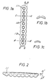
- the plate (1.0) (Fig. 1) is designed such that the cross section along the section line bb, that is, the cross sections along the section line cc, which can be placed through the center of the screw holes or fastening holes (1.1), approximately correspond to half the cross-section along the section line dd in position aa of the plate (1.0) between the fastening holes (1.1).
- This design avoids that the plate (1.0) in the area of the fastening holes (1.1) is prematurely "weakened” due to the degradation of the polymer material by absorption. This results in an elongated basic shape of the osteosynthesis plate, which bulges in the area of the fastening holes (1.2)
- the plate in the middle should be 25% thicker than at the ends.
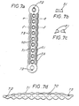
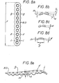
- lateral and longitudinal reinforcements or thickenings of the plate 7.1 in FIGS. 7a-d
- the mounting hole depressions are preferably spherical (FIG. 1b), with elongated holes with an inclined run-in path possibly proving to be advantageous.
- the osteosynthesis plate according to the invention is connected to the bone by means of a fastening device.
- Suitable fastening devices are generally screws, threaded rods, nuts or similarly designed fastening devices with the same function, which are made from a polymer that is resorbable in the body, such as poly-L-lactide, poly-D, L-lactide, polyglycolide, copolymers or polymers or copolymers with resorbable fibers.
- the material properties of the screws can be improved through the use of injection molding processes - as is used in the production of fiber composite materials.
- injection molding processes both in the orientation of the molecular chains in the screw core and in the orientation of the fibers in the production of the composite material, a screw-shaped 45 ° rotation in the clockwise direction must be achieved so that the screw has both the axially longitudinal screw tension and the torque to be tolerated at the same time Can stand.
- a fundamental material improvement is achieved by using the injection molding process (denser packing of the material and cross-linking of the molecular chains).
- the resorbable fastening device consists of a threaded rod (3.0) (Fig. 3) and an associated nut (4.0) with an internal thread (Fig. 4), the threaded rod offering the possibility of a tool attachment for torque transmission at one end (e.g. 3.1 in Fig. 3).
- This approach can be the thread itself - but preferably as a hole, slot or inside or outside hexagon.
- the fastening unit can be screwed into the bone and tightened using any suitable tool, the tightening force of which should be adjustable.
- the threaded rod (3.0) can have a predetermined breaking point (3.3) (FIG. 3), which enables the fastening unit to be replaced effortlessly if the threaded rod fails when it is screwed in.
- the lower end of the threaded rod (3.0) (Fig. 3) can - as will be described later - be provided with an X-ray shadow-producing material or particle (3.2) (Fig. 3), which is in a finely divided layer on the Surface or in compact form inside or only on or in the tip of the screw or the threaded rod (Fig. 3).
- the X-ray shadow-producing material can itself be bio-absorbable or non-bio-absorbable.
- a nut is screwed onto the upper end of the threaded rod, which has a hexagon and which converges spherically at the lower end.
- the nut with the threaded rod attached to it is inserted into the hexagon receptacle of a special device and the thread is screwed through the inserted nut into the internal thread in the device.
- the threaded rod can be screwed into the bone by turning the knurled nut on the device, whereupon the threaded rod is tightened finger-tight until it stops.
- the threaded rod is then tightened using a tensioning mechanism - while at the same time supporting the instrument on the plate to a value that is 10% below the tensile strength.
- the nut is screwed down finger-tight via a second knurled screw of the device, so that the nut is supported on the plate and takes over the axial screw tensile force maintained up to now by the device.
- the axial screw pulling force is applied by the pure pull to the screw end screwed into the device, while the nut only has to be turned down until it catches and maintains this axially built-up screw pull.
- the device is then relaxed and the protruding threaded rod is cut off by means of a hot wire over the nut.
- the hot wire can be run across the threaded rod and the nut at the same time in order to achieve welding, which prevents the screw connection from becoming loose.
- the device for fastening the osteosynthesis plate can consist of a threaded rod (3.0) (FIG. 3) and a nut (4.0) (FIG. 4), the threaded rod made of a resorbable polymer having a shoulder at its upper end - such as a hexagon, square, imbus or a transverse hole (31) - is provided (Fig. 3), which allows the threaded rod to be screwed into the bone.
- the threaded rod at the opposite end of the head of the thread designed for the torque transmission (at the tip) (FIG.
- 3) is provided with one or more particles (3.2) which produce X-ray shadows, which particles themselves are composed of an absorbable or else a non-absorbable material.
- the particle or particles producing the X-ray shadow can, however, also be arranged in another way - as described below - in the screw or the threaded rod.
- the threaded rod itself is provided with a predetermined breaking point (3.3) which, in the event of damage or premature breaking, enables the remainder of the threaded rod that is still in the thread to be easily removed.
- the threaded rod is screwed into the bone using a rod inserted through the transverse hole.
- the threaded rod is preloaded using an auxiliary tool which engages in the thread of the threaded rod and which is supported on the plate (5.0) (Fig. 5) and then secured using the counterpart (4.0).
- the threaded rod can be screwed into the hole prepared in the bone until the X-ray screen ensures that the threaded rod is screwed deep enough due to the x-ray contrasting particle (s) in the rod.
- the threaded rod is pretensioned by means of an auxiliary device which, for example, engages in the devices (3.1) (Fig.
- the protruding ends of the various rods can be cut off, whereby chips or fragments that may get into the wound may not - as e.g. Metal shavings must be removed as they do not cause tissue irritation and are absorbed by the body over time.
- the protruding rods can also - as already described - be removed by means of a hot wire, whereby no chips are produced and with which welding is achieved at the same time, which prevents the screw connection from becoming loose.
- the fibers can be axially introduced into the threaded rods due to the quasi-uniaxial force effect, which, compared to the screws subjected to torsion and tension, brings about a substantial improvement in strength and simplifies production.
- Such screws for example produced by injection molding, also show improved strength values due to the orientation introduced in the axial direction.
- the fastening unit when the fastening unit is overstretched, the screw itself and not the bone is damaged.
- the rod end protruding clearly from the plate can be created by a taper on the threaded rod (3.3) (Fig. 3), a predetermined breaking point, so that the rod breaks in the event of an overload at this predetermined location.
- This broken threaded rod can be unscrewed by hand without further manipulation of the plate or even its removal, which in the other case would inevitably be necessary if a screw with a larger thread diameter was subsequently used and unscrewed all the screws already attached.
- FIG. 3 A preferred embodiment of the fastening unit according to the invention is shown in Figs. 3, 4, 5 and 6 and is described in the following explanatory:
- the threaded rod (3.0) (Fig. 3) has at the end provided for the transmission of the torque a transverse hole (3.1) for receiving a rod into which this can be inserted or screwed.
- a transverse hole (3.1) for receiving a rod into which this can be inserted or screwed.
- an X-ray shadow-producing particle (3.2) is embedded.
- the introduced taper (3.3) is designed as a groove in this example, but can also be designed in any other suitable embodiment.
- the counterpart (4.0) (Fig. 4) is designed on one side as a hemisphere to enable the attachment of screws that are not perpendicular to the plate.
- the counterpart (4.0) (Fig. 4) has four holes (4.1), which should enable screwing with a suitable auxiliary tool.
- the threaded rod is screwed into the bone using a rod inserted through the transverse hole (3.1) until the correct position of the screw (Fig. 5) is determined by X-ray.
- the threaded rod is pre-tensioned using an auxiliary tool that engages in the thread of the rod and is supported on the plate (5.0) and then secured using the counterpart (4.0).
- the holes in the bone fragments can be drilled using a drilling template or drilling jig which is placed on the holes of the osteosynthesis plate.
- Another object of the invention is - as already mentioned - the production of screws or threaded rods that can be made visible by X-ray.
- the screws or threaded rods are given a small calcium phosphate ball by hot pressing in, which enables X-ray visualization. This allows the length of the screw to be determined in the x-ray image and thus gives the operator a control option to assess whether a screw is too long due to incorrect length measurement during the operation.
- Another possibility is the arrangement of several calcium phosphate granules from the tip at a distance of 2 - 3 mm each.
- a screw designed in this way also allows the position of the screw to be assessed or its position in an X-ray image taken directly after surgery Determine length.
- a pin made of calcium phosphate (with a diameter of up to approx. 1 mm) with a length of approx. 5 mm is inserted into the center of the screw, which also opens up the possibility, even after a shortening which may be necessary determine the position and length of the screw by X-ray.
- a very fine-grained calcium phosphate granulate (diameter of the granulate grains up to max. 300 ⁇ m) is applied to the distal half of the screw surface in the outermost layer in the area of the thread of the screw, which can also be made visible in the X-ray image.
- this embodiment has the advantage that the coating of the screw surface in the distal thread area allows the screw to grow on the corresponding bone surface, which is a loosening caused by the micro-movements of the body or even an independent It is difficult to unscrew the screw.
Abstract
Description
Die Erfindung betrifft eine resorbierbare Vorrichtung zur Osteosynthese bestehend aus einer Osteosyntheseplatte und einer Befestigungsvorrichtung sowie Verfahren zu ihrer Herstellung.The invention relates to a resorbable device for osteosynthesis consisting of an osteosynthesis plate and a fastening device, and a method for its production.
Die Anwendung der stabilen Plattenosteosynthese, mit deren Hilfe eine mechanische Verbindung zwischen den beiden Bruchenden einer Fraktur erreicht wird, ist an sich bekannt und kann zur Stabilisierung der verschiedensten Frakturen am menschlichen Skelett nutzbar gemacht werden. Herkömmlicherweise werden die zur Osteosynthese benötigten Platten, Schrauben, Nägel oder Nadeln aus Metall - Edelstählen oder Chrom-Nickel-Legierungen (z.B. vom Typ L 316) -hergestellt, womit im wesentlichen zwei gravierende Nachteile verbunden sind: Zum einen ist der Steifheitsgrad der Metallimplantate deutlich höher als derjenige menschlicher Knochen. Die hieraus resultierende "stress protection" hat einen Knochenabbau (Osteoporosie) zur Folge, welcher seinerseits das Risiko einer erneuten Fraktur - nach dem Entfernen der Metallplatte - erhöht. Zum anderen muß das Implantat nach der Beendigung des Heilungsprozesses in einer weiteren Operation entfernt werden, was nicht nur zu einer mit weiteren Risiken verbundenen Belastung des Patienten führt, sondern auch mit erheblichen Heilungskosten verbunden ist. Weiterhin läßt die ansteigende Zahl der auftretenden Chrom-Nickel-Allergien und die damit verbundenen Komplikationen den Einsatz derartiger Materialien problematisch erscheinen.The use of stable plate osteosynthesis, with the aid of which a mechanical connection between the two fracture ends of a fracture is achieved, is known per se and can be used to stabilize a wide variety of fractures on the human skeleton. Traditionally, the plates, screws, nails or needles required for osteosynthesis are made of metal - stainless steels or chrome-nickel alloys (e.g. of the L 316 type) - which essentially have two serious disadvantages: First, the degree of stiffness of the metal implants is clear higher than that of human bones. The resulting "stress protection" results in bone loss (osteoporosia), which in turn increases the risk of a new fracture after the metal plate has been removed. On the other hand, the implant must be removed in a further operation after the healing process has ended, which not only leads to a burden on the patient associated with further risks, but is also associated with considerable healing costs. Furthermore, the increasing number of chrome-nickel allergies and the associated complications make the use of such materials appear problematic.
Diese Nachteile können durch den Einsatz sogenannter bio-resorbierbarer Polymere überwunden werden. Als biologisch resorbierbare Polymere werden im allgemeinen und im Sinne der Erfindung solche Polymere verstanden, die unter physiologischen Bedingungen zu körpereigenen Substanzen abgebaut und mit dem Stoffwechselkreislauf ausgeschieden werden. Die Verwendung bio-resorbierbarer Materialien bei der Plattenosteosynthese bietet den Vorteil, daß die sonst notwendige Zweitoperation zur Entnahme des Implantates entfällt. Der resorptionsbedingte Abbau des Implantates, mit dem eine entsprechende Minderung der mechanischen Stabilität verbunden ist und der eine zunehmende funktionelle Belastung des Knochens bedingt, welche ihrerseits eine weitere funktionelle Strukturierung im Bruchspalt ermöglicht, verhindert auf diesem Wege die unerwünschte Auswirkung der "stress protection".These disadvantages can be overcome by using so-called bio-absorbable polymers. Biologically resorbable polymers are understood in general and in the sense of the invention to be those polymers which, under physiological conditions, are broken down into the body's own substances and excreted with the metabolic cycle. The use of bioabsorbable materials in plate osteosynthesis offers the advantage that the second operation, which would otherwise be necessary, for removing the implant is eliminated. The resorption-related dismantling of the implant, which is associated with a corresponding reduction in mechanical stability and which causes an increasing functional load on the bone, which in turn enables further functional structuring in the fracture gap, prevents the undesirable effect of the "stress protection" in this way.
Zahlreiche Patente bzw. Patentanmeldungen haben resorbierbare Implantate für die Plattenosteosynthese zum Gegenstand:
EP 0258 692, US-PS 46 55 777, EP 0204 931, EP 0011 528 und US-PS 43 29 743.Numerous patents and patent applications deal with resorbable implants for plate osteosynthesis:
EP 0258 692, US-PS 46 55 777, EP 0204 931, EP 0011 528 and US-PS 43 29 743.
In diesen Patenten wird davon ausgegangen, daß die Festigkeit der resorbierbaren Polymere für einen Einsatz in der Osteosynthese nicht ausreicht. Daher wurde vorgeschlagen, verschiedenartige Fasern als Verstärkungsmaterial zur Erhöhung der mechanischen Belastbarkeit einzusetzen, wobei diese aus resorbierbaren oder in der Regel aber aus nicht-resorbierbaren Materialien bestehen können. Die Form der Platten oder Schrauben wird dabei fast vollständig von den entsprechenden Osteosynthesevorrichtungen aus Metall übernommen. Es hat sich in der Praxis jedoch gezeigt, daß die für die "Metallosteosynthese" bewährten Formen und Konstruktionen bei der Verwendung von resorbierbaren Polymeren entscheidende Nachteile aufweisen. So wurde bislang beispielsweise außer acht gelassen, daß die aus der Verwendung von Kunststoff resultierenden Gestaltungsmöglichkeiten andere, wesentlich belastungsgerechtere Konstruktionen zulassen, deren Verwendung zudem für den operierenden Arzt mit erheblichen Erleichterungen verbunden sein kann.
Herkömmliche Osteosyntheseplatten aus resorbierbaren Polymeren weisen beispielsweise den Nachteil auf, daß sie - insbesondere im Bereich der Schraubenlöcher - relativ leicht brechen.These patents assume that the strength of the resorbable polymers is not sufficient for use in osteosynthesis. It has therefore been proposed to use different types of fibers as reinforcing material to increase the mechanical strength, which may consist of resorbable or generally non-resorbable materials. The shape of the plates or screws is almost completely adopted by the corresponding metal osteosynthesis devices. However, it has been shown in practice that the forms which have been tried and tested for "metallosteosynthesis" and designs have significant disadvantages when using resorbable polymers. So far, for example, it has been neglected that the design options resulting from the use of plastic permit other, much more load-bearing constructions, the use of which can also be considerably easier for the operating doctor.
Conventional osteosynthesis plates made of resorbable polymers have the disadvantage, for example, that they break relatively easily, particularly in the area of the screw holes.
Die bisher im Stand der Technik vorgeschlagenen Ausführungsformen für Schrauben weisen ebenfalls Nachteile auf, so zum Beispiel, daß sehr viele verschiedene Längen zur Verfügung stehen müssen, um den Anforderungen jeder individuellen Fraktur gerecht werden zu können. Die Länge der benötigten Schrauben wird zur Zeit noch mit Meßfühlern an den in den betreffenden Knochen vorgebohrten Löchern ermittelt. Dies setzt bei dem jeweiligen Operateur ein großes Maß an Erfahrung voraus. Entsprechend der gemessenen Länge können dann erst während der Operation geeignete Schrauben ausgesucht werden. Bei der Verwendung von Metallschrauben erweist sich ferner der Umstand als nachteilig, daß beim Festziehen der Schrauben das Gewinde im Knochen überdreht werden kann, woraus sich entweder die Notwendigkeit ergibt, ein Ersatzloch bohren zu müssen, oder aber eine neue Schraube mit einem größerem Durchmesser verwendet werden muß, was jedoch erst nach einer aufwendigen Entfernung der ursprünglich eingedrehten Schraube möglich ist. Auf der anderen Seite erwächst beim Einsatz von Schrauben aus resorbierbaren Materialien der Nachteil, daß beim Einschrauben zwar nicht das Gewinde im Knochen zerstört wird, sondern - aufgrund der geringen mechanischen Festigkeit - das Gewinde derSchraube selbst oder aber die Schraube unterhalb des Schraubenkopfes abreißt. Diese Schrauben müssen zum Entfernen ausgebohrt und anschließend ersetzt werden.The previously proposed embodiments for screws also have disadvantages, for example that very many different lengths must be available in order to be able to meet the requirements of each individual fracture. The length of the screws required is currently being determined using sensors on the holes predrilled in the bones in question. This requires a great deal of experience from the respective surgeon. Depending on the measured length, suitable screws can only be selected during the operation. If metal screws are used, the fact that the thread in the bone can be over-tightened when the screws are tightened also proves disadvantageous, which either results in the need to drill a replacement hole, or else a new screw with a larger diameter is used must what however, this is only possible after the originally screwed-in screw has been removed. On the other hand, when using screws made of resorbable materials, the disadvantage arises that while screwing in, the thread in the bone is not destroyed, but - due to the low mechanical strength - the thread of the screw itself or the screw below the screw head is torn off. These screws must be drilled out for removal and then replaced.
Diese vergleichsweise geringe mechanische Stabilität bedingt, daß die Schrauben aus resorbierbaren Polymeren zum Befestigen der Platte nicht so fest angezogen werden können, daß die erforderliche geringe Verschiebebeweglichkeit zwischen der Platte und den Knochenhälften erzielt wird und somit ein einwandfreies Zusammenwachsen der Bruchstücke nicht gewährleistet ist. Je geringer die freie Beweglichkeit der Bruchstücke (Verschiebebeweglichkeit) ist, desto größer sind die Heilungsaussichten des Bruches.This comparatively low mechanical stability means that the screws made of resorbable polymers for fastening the plate cannot be tightened so tightly that the required low mobility between the plate and the bone halves is achieved and thus a perfect growth of the fragments is not guaranteed. The lower the free mobility of the fragments (mobility), the greater the chances of the fracture healing.
Ein weiterer Nachteil von resorbierbaren Syntheseschrauben besteht darin, daß sie keinen Röntgenkontrast erzeugen und somit der Operateur keine Möglichkeit besitzt, die richtige Lage der Schrauben zu beurteilen.Another disadvantage of resorbable synthetic screws is that they do not produce an X-ray contrast and thus the surgeon has no way of assessing the correct position of the screws.
Es ist die Aufgabe der vorliegenden Erfindung, eine resorbierbare Vorrichtung zur Osteosynthese zur Verfügung zu stellen, die die Verschiebebeweglichkeit zwischen der Platte und den Knochenbruchstücken auf das für das komplikationslose Zusammenwachsen der Knochen erforderliche Maß reduziert.It is the object of the present invention to provide a resorbable device for osteosynthesis which reduces the mobility between the plate and the bone fragments to the extent necessary for the bone to grow together without complications.
Es ist weiterhin die Aufgabe der vorliegenden Erfindung, Vorrichtungen zur Befestigung der Osteosyntheseplatte aus resorbierbaren Polymeren zur Verfügung zu stellen, die im Falle ihrer Beschädigung oder Zerstörung leicht aus dem Knochen entfernt und ersetzt werden können, um die eventuell notwendige Entfernung der ganzen Befestigungsvorrichtung zu vermeiden.It is a further object of the present invention to provide devices for fastening the osteosynthesis plate made of resorbable polymers which, if damaged or destroyed, can be easily removed from the bone and replaced in order to avoid the removal of the entire fastening device which may be necessary.
Eine weitere Aufgabe der vorliegenden Erfindung besteht darin, Befestigungsvorrichtungen zur Verfügung zu stellen, die hinsichtlich ihrer Länge ohne weiteren Aufwand in das jeweilige Bohrloch eingepaßt werden können, um somit eine Lagerhaltung von einer Vielzahl von Schrauben bzw. Befestigungsvorrichtungen verzichtbar zu machen.Another object of the present invention is to provide fastening devices which can be fitted into the respective borehole in terms of their length without further effort, in order to make storage of a large number of screws or fastening devices dispensable.
Eine weitere Aufgabe der vorliegenden Erfindung besteht darin, eine kunststoffgerechte Gestaltung der Befestigungsvorrichtung vorzunehmen, die gegenüber der reinen Kopie der Gestalt von Metallvorlagen aus Kunststoff höhere Anzugskräfte erlaubt.Another object of the present invention is to carry out a plastic-appropriate design of the fastening device, which allows higher tightening forces than the pure copy of the shape of metal templates made of plastic.
Eine weitere Aufgabe der vorliegenden Erfindung besteht darin, eine Osteosynthese-Vorrichtung aus resorbierbaren Polymeren röntgenologisch sichtbar zu machen.Another object of the present invention is to make an osteosynthesis device made of resorbable polymers radiologically visible.
Die Aufgabe der vorliegenden Erfindung wird durch eine resorbierbare Osteosynthesevorrichtung bestehend aus einer mit Schraubenlöchern versehenen Platte aus einem resorbierbaren Polymer oder Copolymer, die auf der dem Knochen zugewandten Seite mit Calciumphosphat- und/oder Hydroxylapatitgranulat beschichtet ist sowie mindestens zweier Befestigungsvorrichtungen bestehend aus einer Gewindestange und der dazugehörigen Mutter gelöst.The object of the present invention is achieved by a resorbable osteosynthesis device consisting of a plate provided with screw holes made of a resorbable polymer or copolymer, which is coated on the side facing the bone with calcium phosphate and / or hydroxylapatite granules and at least two fastening devices consisting of a threaded rod and the associated mother solved.
Geeignete resorbierbare Polymere aus denen die Platte, die Gewindestangen und die Muttern bestehen können sind Polymere und Copolymere auf der Basis folgender Monomere: L-Lactid, D,L-Lactid, Glycolid. Falls es gewünscht oder erforderlich ist, können die Polymere bzw. Copolymere durch resorbierbare Fasern verstärkt werden. Die Verfahren zur Herstellung und Bearbeitung geeigneter Polymere und Copolymere sind aus dem Stand der Technik bekannt und brauchen nicht näher erörtert werden.Suitable resorbable polymers from which the plate, the threaded rods and the nuts can be made are polymers and copolymers based on the following monomers: L-lactide, D, L-lactide, glycolide. If desired or necessary, the polymers or copolymers can be reinforced by resorbable fibers. The processes for the production and processing of suitable polymers and copolymers are known from the prior art and need not be discussed in more detail.
Die Form der erfindungsgemäßen Platte kann in sehr weiten Bereichen beliebig variiert werden, soweit dies nicht im Widerspruch zu den Eigenschaften der verwendeten Polymermaterialien (Bruchfestigkeit, Abbaurate etc.) und der beabsichtigten Verwendung (Art des Bruches etc.) steht. Ein wesentliches Merkmal der erfindungsgemäßen Platte ist, daß sie an ihrer Unterseite - d.h. der dem Knochen zugewandten Seite -eine Beschichtung aus Calciumphosphat und/oder Hydroxylapatit - vorzugsweise in Form eines Granulates oder kleiner Kügelchen - aufweist.The shape of the plate according to the invention can be varied in a very wide range, provided that this does not conflict with the properties of the polymer materials used (breaking strength, rate of degradation etc.) and the intended use (type of break etc.). An essential feature of the plate according to the invention is that on its underside - i.e. the side facing the bone has a coating of calcium phosphate and / or hydroxyapatite - preferably in the form of granules or small spheres.
Einerseits erfährt die Unterseite der erfindungsgemäßen Platte durch die Beschichtung eine Aufrauhung, die im Vergleich zu den bisher verwandten Osteosyntheseplatten aus bio-resorbierbaren Materialien bei gleicher Andruckkraft eine geringere Verschiebebeweglichkeit gewährleistet - andererseits sichert die mit Calciumphosphat bzw. Hydroxylapatit beschichtete Platte ein baldiges Anwachsen an der Knochenoberfläche, da auch industriell hergestelltes Calciumphosphatkeramik-Granulat weitestgehend dem im Knochen befindlichen Mineral entspricht.On the one hand, the underside of the plate according to the invention is roughened by the coating, which, compared to the previously used osteosynthesis plates made of bio-resorbable materials, guarantees less mobility with the same pressure force - on the other hand, the plate coated with calcium phosphate or hydroxyapatite ensures an early growth on the bone surface , because even industrially produced calcium phosphate ceramic granulate largely corresponds to the mineral in the bone.
Durch das Anwachsen der mit Calciumphosphatkeramik-Granulat beschichteten bio-resorbierbaren Osteosyntheseplatte an der Knochenoberfläche kommt es zu einer zusätzlichen mechanischen Stabilisierung der Platte auf der Knochenoberfläche, wodurch gleichzeitig die unerwünschte Beweglichkeit zwischen Knochen und Platte bei vorgegebener axialer Schraubenzugkraft auf ein Mindestmaß verringert wird. Diese kann von ausschlaggebender Bedeutung sein, falls es zu einem vorzeitigen Bruch der Befestigungsvorrichtung (nachfolgend auch als Gewindestange bezeichnet oder auch Schraube genannt) infolge beginnender Resorption und der damit verbundenen mechanischen Schwächung der Schrauben kommt, wobei davon ausgegangen werden kann, daß sich die Resorption bei den unter hoher mechanischer Belastung stehenden filigranen Schrauben schneller auswirkt als bei den wesentlich massiver ausgeführten Platten.The growth of the bio-resorbable osteosynthesis plate coated with calcium phosphate ceramic granules on the bone surface leads to an additional mechanical stabilization of the plate on the bone surface, which at the same time minimizes the undesired mobility between the bone and plate with a given axial screw tension. This can be of crucial importance if the fastening device (hereinafter also referred to as the threaded rod or screw) is prematurely broken due to the beginning of absorption and the mechanical weakening of the screws associated with it, whereby it can be assumed that the absorption increases affects the filigree screws, which are subject to high mechanical loads, faster than the much more solid plates.
Durch die Calciumphosphat- bzw. Hydroxylapatit-Beschichtung - im folgenden auch Calciumphosphatkeramik-Granulat genannt - wird zudem die Möglichkeit eröffnet, das Implantat röntgenologisch sichtbar zu machen. Auf diesem Wege können Form und Größe des Implantates einschließlich der Lagebeziehung zum stabilisierten Knochen im Röntgenbild beurteilt werden. Weiterhin ist ein eventueller Bruch oder eine spätere Dislokation der Platte im Röntgenbild zu erkennen. Die Calciumphosphatkeramiken unterliegen ebenfalls der Resorption, auch wenn diese etwas größere Zeiträume beansprucht als dies z.B. beim Polylactid der Fall ist.The calcium phosphate or hydroxylapatite coating - also called calcium phosphate ceramic granules in the following - also opens up the possibility of making the implant visible radiologically. In this way, the shape and size of the implant, including the positional relationship to the stabilized bone, can be assessed in the X-ray image. A possible break or a later dislocation of the plate can also be seen in the X-ray image. The calcium phosphate ceramics are also subject to absorption, even if this takes somewhat longer periods than is the case with polylactide, for example.
Zur Herstellung der erfindungsgemäßen Platte können folgende Techniken angewandt werden: Das Calciumphosphatkeramik-Granulat wird heiß in die Oberfläche einer vorgefertigten Platte eingepresst. Die Anwendung dieser Methode hat eine mechanisch sehr feste Bindung des Granulates an dem Träger zur Folge. Die Aufbringung kann beispielsweise aber auch in der Weise erfolgen, daß z.B. eine 0,5 - 1,0 mm dicke Polylactidfolie auf eine heiße dicht liegende Granulatschicht heiß aufgepresst wird, womit ein Verbund des Granulates erzielt wird. Es erweist sich als vorteilhaft, wenn die Granulatkörner nicht zu dicht nebeneinander liegen; hierdurch wird vermieden, daß das Granulat beim Biegen der Platten abplatzt. Die so erhaltene granulatbeschichtete Polylactidfolie wird in einem geeigneten Spritzgußwerkzeug ausgelegt und mit Polylactid überspritzt, wobei es zu einer innigen Verbindung der mit Hydroxylapatit bzw. mit Calciumphosphat beschichteten Polylactidfolie mit dem durch Spritzguß erzeugten Implantatkörper kommt. Die Herstellung der granulatbeschichteten Folie kann großflächig erfolgen. Im anschließenden Schritt kann die Folie auf die gewünschte Plattengröße zugeschnitten werden.The following techniques can be used to produce the plate according to the invention: The calcium phosphate ceramic granulate is hot-pressed into the surface of a prefabricated plate. The use of this method results in a mechanically very firm binding of the granules to the carrier. The application can also take place, for example, in such a way that, for example, a 0.5-1.0 mm thick polylactide film is hot pressed onto a hot, close-lying granulate layer, whereby a bond of the granulate is achieved. It proves to be advantageous if the granules are not too close together; this prevents the granules from flaking off when the plates are bent. The granule-coated polylactide film obtained in this way is laid out in a suitable injection molding tool and overmolded with polylactide, the polylactide film coated with hydroxyapatite or calcium phosphate being intimately bonded to the implant body produced by injection molding. The granulate-coated film can be produced over a large area. In the subsequent step, the film can be cut to the desired plate size.
In einer weiteren Ausführungsform können die Calciumphosphatkeramik-Granulatkörner elektrostatisch an einer Wand des Werkzeuges fixiert werden und anschließend wie oben beschrieben überspritzt werden. Weiterhin besteht die Möglichkeit die Beschichtung auf die Weise durchzuführen, daß die Granulatkörner an kleinen Bohrungen eines Spritzgußwerkzeuges, die einen kleineren Durchmesser als die Granulatkörner aufweisen, während des anschließenden Spritzvorganges durch Ansaugen in dieser Posititon gehalten werden. Die erfindungsgemäßen Platten können unter Erwärmung verformt werden, so daß sie der Knochenoberfläche angepaßt werden können. Dies kann auch vom Operateur -z.B. mit einem speziellen Heißluftgebläse oder einem für diese Zwecke speziell ausgestalteten Mikrowellengenerator - im Operationssaal durchgeführt werden. Ein nennenswertes Abplatzen der Granulat-Beschichtung ist dabei nicht zu beobachten. Die spontane maximale Zugkraft einer bei den Versuchen verwendeten Polylactid-Platte von 2000 N (ermittelt mit einer Zwick Material-Prüfmaschine) bestand nach der Hitzebehandlung der Oberfläche unverändert weiter.In a further embodiment, the calcium phosphate ceramic granules can be fixed electrostatically to a wall of the tool and then overmolded as described above. Furthermore, it is possible to carry out the coating in such a way that the granules pass through small holes in an injection molding tool which have a smaller diameter than the granules during the subsequent spraying process Suction should be kept in this position. The plates according to the invention can be deformed with heating so that they can be adapted to the surface of the bone. This can also be carried out by the surgeon in the operating room, for example using a special hot air blower or a microwave generator specially designed for this purpose. There was no noticeable flaking of the granulate coating. The spontaneous maximum tensile force of a polylactide plate of 2000 N used in the tests (determined with a Zwick material testing machine) remained unchanged after the heat treatment of the surface.
In einer weiteren Ausführungsform können alle nicht dem Knochen zugewandten Flächen der Platte einschließlich die der Schraubenköpfe mit einem niedermolekularen lediglich geringe mechanische Festigkeit aufweisenden Film eines geeigneten Polymeren - z.B. mit einem Polylactidfilm - überzogen werden, welcher kolloidal verteiltes Silber enthält. Die Oberflächenbeschichtung - von der Dicke bis zu 1 mm - verhindert einerseits aufgrund der oligo-dynamischen antibakteriellen Wirksamkeit des Silbers eine Keimbesiedlung der Oberfläche des Implantates in den ersten Wochen nach der Operation; zum zweiten wird eine schemenhafte röntgenologische Sichtbarmachung des Implantates ermöglicht. Um eine primäre Gewebetoxizität zu vermeiden, ist es erforderlich, die der Platte näher liegenden Schichten stärker mit Silber anzureichern als diejenigen Schichten an der Oberfläche. Die höherangereicherten aber tieferliegenden Schichten, werden keinen toxikologisch bedenklichen Einfluß ausüben, da im Verlaufe der Resorption Anteile des Silbers aus den tiefergelegenen Schichten herausgelöst werden, so daß nach dem Aberodieren der jeweils an der Oberfläche liegenden Schichten das Gewebe mit einer Schicht in Kontakt kommt, die eine bereits reduzierte Konzentration an kolloidalem Silber - bezogen auf die Ausgangskonzentration - aufweist, wodurch Schädigungen des Gewebes vermieden werden.In a further embodiment, all surfaces of the plate not facing the bone, including those of the screw heads, can be coated with a low-molecular, low-mechanical strength film of a suitable polymer, for example with a polylactide film, which contains colloidally distributed silver. The surface coating - from the thickness up to 1 mm - on the one hand prevents the colonization of the surface of the implant in the first weeks after the operation due to the oligo-dynamic antibacterial effectiveness of the silver; secondly, a schematic radiological visualization of the implant is made possible. In order to avoid primary tissue toxicity, it is necessary to enrich the layers closer to the plate with silver more than those layers on the surface. The higher-enriched but deeper layers will have no toxicologically harmful influence, since portions of the silver will be released from the deeper layers in the course of the absorption, so that after the layers on the surface have been eroded, the tissue comes into contact with a layer that has a already reduced concentration of colloidal silver - based on the initial concentration - which prevents damage to the tissue.
In einer weiteren Ausführungsform kann die Calciumphosphatkeramik-Granulatschicht der Platte selbst mit feinkörnigem Silberphosphat bis zu 30 % (bezogen auf das Gesamtgewicht des Granulates) angereichert werden, um dadurch auch auf dieser Seite des Implantats eine antibakterielle Wirkung zu erzielen.In a further embodiment, the calcium phosphate ceramic granulate layer of the plate itself can be enriched with fine-grained silver phosphate up to 30% (based on the total weight of the granulate) in order to achieve an antibacterial effect on this side of the implant as well.
An Stelle von kolloidal verteiltem Silber können die beschriebenen Schichten auch PVP-Jod [Polyvinylpyrrolidon-Jod-Komplex bzw. Poly(1-vinyl-2-pyrrolidin-2-on)-Jod-Komplex] in Konzentrationen von 5 % bis 40 % enthalten, wodurch ebenfalls eine antibakterielle Wirkung als auch eine röntgenologische Sichtbarmachung der Platte erreicht wird.Instead of colloidally distributed silver, the layers described can also contain PVP iodine [polyvinylpyrrolidone-iodine complex or poly (1-vinyl-2-pyrrolidin-2-one) iodine complex] in concentrations of 5% to 40% , which also achieves an antibacterial effect and an X-ray visualization of the plate.
Eine antibakterielle bzw. bakteriostatische Wirkung kann weiterhin durch Beaufschlagung mit thermostabilen Antibiotika aus verschiedenen Gruppierungen unter Bevorzugung von denjenigen Antibiotika mit breitem Wirkungsspektrum - wie z.B. Aminoglycoside, Gyrase-Hemmer oder Vancomycin - erfolgen. Bei einer derartigen Beschichtung braucht auf eine Systemtoxizität keine Rücksicht genommen werden, da nur geringe Mengen im Serum nachweisbar werden, die weit unterhalb der Toxizitätsgrenze liegen, welche bei einer intravenösen Applikation beachtet werden muß.An antibacterial or bacteriostatic effect can also be achieved by exposure to thermostable antibiotics from different groups, with preference for those antibiotics with a broad spectrum of activity - such as e.g. Aminoglycosides, gyrase inhibitors or vancomycin - take place. With such a coating, system toxicity need not be taken into account, since only small amounts are detectable in the serum, which are far below the toxicity limit, which must be observed with an intravenous application.
Die Platte selbst wird, wie aus der Entwicklung von Metallplatten zur Stabilisierung von Knochen bekannt ist, im wesentlichen durch Biegung und Zugbeanspruchung belastet. Es ist daher anzustreben, im Spritzgußverfahren durch die Anordnung der Spritzdüsen eine Längsorientierung der Molekülketten zu erreichen. Die notwendigen technischen Voraussetzungen zur Verarbeitung der Polymere sind dem Fachmann bekannt. Es wird jedoch darauf hingewiesen, daß das zu spritzende Gut extrem trocken gehalten werden muß, da bei höheren Temperaturen mit jedem Promille Wassergehalt der Anteil an Kettenabbauprodukten steigt. Dies wirkt sich direkt auf das Abbauverhalten des Polymeren aus. Wie schon erwähnt, besteht die Möglichkeit, in Pulverform vorliegende und thermostabile Antibiotika, wie z.B. Aminoglykoside oder Gyrase-Hemmer, zuzufügen. Da deren thermische Belastung beim Aufpressen nur für eine äußerst kurze Zeitspanne akut wird, kann dabei die vom jeweiligen Hersteller angegebene tolerierbare Temperaturobergrenze überschritten werden, ohne daß daraus schwerwiegende Nachteile für das Präparat wie auch für das Implantat resultieren.As is known from the development of metal plates for the stabilization of bones, the plate itself is essentially loaded by bending and tensile stress. It is therefore desirable to achieve a longitudinal orientation of the molecular chains in the injection molding process by arranging the spray nozzles. The person skilled in the art is familiar with the necessary technical requirements for processing the polymers. However, it is pointed out that the material to be sprayed must be kept extremely dry, since at higher temperatures the proportion of chain degradation products increases with each alcohol content. This has a direct impact on the degradation behavior of the polymer. As already mentioned, it is possible to add thermostable antibiotics such as aminoglycosides or gyrase inhibitors in powder form. Since the thermal load on pressing only becomes acute for an extremely short period of time, the tolerable upper temperature limit specified by the respective manufacturer can be exceeded without this resulting in serious disadvantages for the preparation as well as for the implant.
Die Temperaturführung und das Nachspritzen während des Aushärtens ist derart durchzuführen, daß im Zentrum keine Hohlräume entstehen und die Wärme möglichst schnell abgeführt werden kann, um die thermische Belastung des Polymers so gering wie möglich zu halten.The temperature control and the post-injection during curing must be carried out in such a way that there are no voids in the center and the heat can be dissipated as quickly as possible in order to keep the thermal load on the polymer as low as possible.
In einer besonderen Ausführungsform wird die erfindungsgemäße Platte durch ein in das Polymer eingelagertes Fasermaterial verstärkt.In a special embodiment, the plate according to the invention is reinforced by a fiber material embedded in the polymer.
Als Fasermaterial wird bevorzugt verstrecktes Poly-L-lactid verwendet, während die Matrix vorzugsweise aus Poly-D,L-lactid besteht. Die Zugfestigkeit der erfindungsgemäßen Platten dieser Ausführungsform ist im Vergleich zu der nicht verstärkten Platte bis um einen Faktor von 10 größer. Vorteilhaft erweisen sich extrudierte Fasern, die beim Aushärten zusätzlich verstreckt werden. Da die Platten im wesentlichen einer Zug- und Biegebelastung ausgesetzt sind, sollten die Fasern längsorientiert sein und der Winkel, den die Fasern zueinander aufweisen, 30° nicht überschreiten. Als Temperaturschutz bei der Herstellung für die Fasern erweist sich gegebenenfalls ein dünner Überzug aus niedermolekularem L-Lactid oder D,L-Lactid von Vorteil. Auch der verstärkten Platte kann kolloidal verteiltes Silber, PVP-Jod oder ein wärmebeständiges und in Pulverform vorliegendes Antibiotikum zugemischt werden.Stretched poly-L-lactide is preferably used as the fiber material, while the matrix preferably consists of poly-D, L-lactide. The tensile strength of the plates according to the invention of this embodiment is up to a factor of 10 greater than that of the non-reinforced plate. Extruded fibers, which are additionally stretched during curing, have proven to be advantageous. Since the plates are essentially subjected to tensile and bending loads, the fibers should be longitudinally oriented and the angle which the fibers have to one another should not exceed 30 °. A thin coating of low molecular weight L-lactide or D, L-lactide may prove to be advantageous as temperature protection for the production of the fibers. Colloidally distributed silver, PVP iodine or a heat-resistant antibiotic in powder form can also be added to the reinforced plate.
Die Formgebung der Platten richtet sich in erster Linie nach dem Indikationsgebiet. Trotz unterschiedlicher Länge bzw. der generell unterschiedlichen Größe der Platten - in Abhängigkeit von der geplanten Anwendung - weisen die Osteosyntheseplatten und die Befestigungsvorrichtungen vorzugsweise folgende Grundformen auf:
- Fig. 1a zeigt eine bevorzugte Ausführungsform der erfindungsgemäßen Osteosyntheseplatte (1.0).
- Fig. 1b zeigt einen Querschnitt durch die erfindungsgemäße Osteosyntheseplatte (1.0) aus Fig. 1a längs der Schnittlinie cc.
- Fig. 1c zeigt einen Querschnitt durch die erfindungsgemäße Osteosyntheseplatte (1.0) aus Fig. 1a längs der Schnittlinie dd.
- Fig. 2 zeigt eine Seitenansicht der erfindungsgemäßen Osteosyntheseplatte, die in der Mitte eine um ca. 25 % stärkere Dicke aufweist als an den Enden (h¹ = 1/4 h²).
- Fig. 3 zeigt die Gewindestange (3.0) der erfindungsgemäßen Befestigungsvorrichtung, welche ein Querloch (3.1), ein einen Röntgenkontrast erzeugendes Teilchen (3.2) und eine Verjüngung (3.3) (Sollbruchstelle) aufweist.
- Fig. 4 zeigt eine bevorzugte Ausführungsform einer Mutter (4.0) der erfindungsgemäßen Befestigungsvorrichtung, welche gegebenenfalls mehrere Vorrichtungen (4.1) zur Übertragung eines Drehmomentes aufweist.
- Fig. 5 zeigt eine erfindungsgemäße Osteosyntheseplatte (5.0), welche mit den erfindungsgemäßen Befestigungsvorrichtungen, Gewindestange (3.0) und der Mutter (4.0) auf den Knochenfragmenten angebracht ist.
- Fig. 6 zeigt die erfindungsgemäße Vorrichtung zur Osteosynthese nach dem Abschneiden der Gewindestangen.
- Fig. 7a zeigt eine weitere bevorzugte Ausführungsform einer erfindungsgemäßen Osteosyntheseplatte (7.0), welche im zentralen Teil mit in parallel zur Längsrichtung verlaufenden Verstärkungen (7.1) versehen ist sowie Verbreiterungen im Bereich der Schraubenlöcher (7.3) aufweist. Die erfindungsgemäße Osteosyntheseplatte (7.0) weist an beiden Enden Einkerbungen (7.2) zum Einsetzen eines Plattenspanngerätes auf.
- Fig. 7b zeigt einen Querschnitt durch die erfindungsgemäße Osteosyntheseplatte (7.0) aus Fig. 7a längs der Schnittlinie ee.
- Fig. 7c zeigt einen Querschnitt bzw. die resultierenden Querschnittsflächen bei einem Schnitt durch die erfindungsgemäße Osteosyntheseplatte (7.0) aus Fig. 7a längs der Schnittlinie ff.
- Fig. 7d zeigt die Seitenansicht der erfindungsgemäßen Osteosyntheseplatte (7.0) aus Fig. 7a mit der Verstärkung (7.1) und den Einkerbungen (7.2) zum Einsetzen eines Plattenspanngerätes.
- Fig. 8a zeigt eine weitere bevorzugte Ausführungsform der erfindungsgemäßen Vorrichtung zur Osteosynthese in Form einer Außenknöchelplatte (8.0) mit den Schnittlinien gg, kk und 11, wobei die Länge x der Platte etwa 10 cm beträgt.
- Fig. 8b zeigt einen Querschnitt durch die erfindungsgemäße Osteosyntheseplatte (8.0) aus Fig. 8a längs der Schnittlinie gg, wobei die Dicke u der Platte ca. 2 mm und die Höhe der Wölbung m ca. 2 mm beträgt.
- Fig. 8c zeigt einen Querschnitt durch die erfindungsgemäße Osteosyntheseplatte (8.0) aus Fig. 8a längs der Schnittlinie kk, wobei die Dicke der Platte v ca. 1,8 mm beträgt.
- Fig. 8d zeigt einen Querschnitt durch die erfindungsgemäße Osteosyntheseplatte (8.0) aus Fig. 8a längs der Schnittlinie 11, wobei die Dicke w der Platte ca. 1,5 mm und die Höhe n der Wölbung ca. 1 mm beträgt.
- Fig. 8e zeigt die Seitenansicht der Außenknöchelplatte (8.0) mit den Lagen der Schnittebenen in Fig. 8a und den Höhen der Wölbungen m und n.
- 1a shows a preferred embodiment of the osteosynthesis plate (1.0) according to the invention.
- 1b shows a cross section through the osteosynthesis plate (1.0) according to the invention from FIG. 1a along the section line cc.
- 1c shows a cross section through the osteosynthesis plate (1.0) according to the invention from FIG. 1a along the section line dd.
- Fig. 2 shows a side view of the osteosynthesis plate according to the invention, which has a thickness of about 25% thicker in the middle than at the ends (h 1 = 1/4 h 2).
- 3 shows the threaded rod (3.0) of the fastening device according to the invention, which has a transverse hole (3.1), a particle (3.2) which produces an X-ray contrast and a taper (3.3) (predetermined breaking point).
- Fig. 4 shows a preferred embodiment of a nut (4.0) of the fastening device according to the invention, which optionally has a plurality of devices (4.1) for transmitting a torque.
- 5 shows an osteosynthesis plate (5.0) according to the invention, which is attached to the bone fragments with the fastening devices, threaded rod (3.0) and the nut (4.0) according to the invention.
- 6 shows the device for osteosynthesis according to the invention after the threaded rods have been cut off.
- 7a shows a further preferred embodiment of an osteosynthesis plate (7.0) according to the invention, which is provided in the central part with reinforcements (7.1) running parallel to the longitudinal direction and has widenings in the area of the screw holes (7.3). The osteosynthesis plate (7.0) according to the invention has notches (7.2) at both ends for inserting a plate tensioning device.
- 7b shows a cross section through the osteosynthesis plate (7.0) according to the invention from FIG. 7a along the section line ee.
- 7c shows a cross-section or the resulting cross-sectional areas in a section through the osteosynthesis plate (7.0) according to the invention from FIG. 7a along the section line ff.
- FIG. 7d shows the side view of the osteosynthesis plate (7.0) according to the invention from FIG. 7a with the reinforcement (7.1) and the notches (7.2) for inserting a plate tensioning device.
- 8a shows a further preferred embodiment of the device for osteosynthesis according to the invention in the form of an outer ankle plate (8.0) with the cutting lines gg, kk and 11, the length x of the plate being approximately 10 cm.
- 8b shows a cross section through the osteosynthesis plate (8.0) according to the invention from FIG. 8a along the section line gg, the thickness u of the plate being approximately 2 mm and the height of the curvature m being approximately 2 mm.
- FIG. 8c shows a cross section through the osteosynthesis plate (8.0) according to the invention from FIG. 8a along the section line kk, the thickness of the plate v being approximately 1.8 mm.
- FIG. 8d shows a cross section through the osteosynthesis plate (8.0) according to the invention from FIG. 8a along the section line 11, the thickness w of the plate being approximately 1.5 mm and the height n of the curvature approximately 1 mm.
- 8e shows the side view of the outer ankle plate (8.0) with the positions of the sectional planes in FIG. 8a and the heights of the curvatures m and n.
Je nach Verwendungszweck bzw. Einsatzgebiet können andere Plattenabmessungen bzw. Wölbungshöhen vorteilhafter sein.Depending on the intended use or area of application, other plate dimensions or curvature heights may be more advantageous.
Die Platte (1.0) (Fig. 1) ist derart gestaltet, daß der Querschnitt längs der Schnittlinie bb, das heißt die Querschnitte, die längs der Schnittlinie cc, die durch den Mittelpunkt der Schraubenlöcher bzw. Befestigungslöcher (1.1) gelegt werden kann, ungefähr dem halben Querschnitt längs der Schnittlinie dd in der Lage aa der Platte (1.0) zwischen den Befestigungslöchern (1.1) entsprechen. Durch diese Formgebung wird vermieden, daß die Platte (1.0) im Bereich der Befestigungslöcher (1.1) infolge des Abbaus des Polymermaterials durch Resorption vorzeitig "geschwächt" wird. Dadurch bedingt ergibt sich eine längliche Grundform der Osteosyntheseplatte, die im Bereich der Befestigungslöcher Ausbuchtungen (1.2)The plate (1.0) (Fig. 1) is designed such that the cross section along the section line bb, that is, the cross sections along the section line cc, which can be placed through the center of the screw holes or fastening holes (1.1), approximately correspond to half the cross-section along the section line dd in position aa of the plate (1.0) between the fastening holes (1.1). This design avoids that the plate (1.0) in the area of the fastening holes (1.1) is prematurely "weakened" due to the degradation of the polymer material by absorption. This results in an elongated basic shape of the osteosynthesis plate, which bulges in the area of the fastening holes (1.2)
Weiterhin soll die Platte in der Mitte (Fig. 2) eine um 25 % stärkere Dicke aufweisen als an den Enden. Darüber hinaus wird durch seitliche und in Längsrichtung verlaufende Verstärkungen bzw. Verdickungen der Platte (7.1 in Fig. 7a-d) im wesentlichen im zentralen Teil der Platte eine Stabilisierung der Platte erreicht.Furthermore, the plate in the middle (FIG. 2) should be 25% thicker than at the ends. In addition, lateral and longitudinal reinforcements or thickenings of the plate (7.1 in FIGS. 7a-d) essentially stabilize the plate in the central part of the plate.
Dabei sollten diese Verstärkungen bzw. Verdickungen nur so hoch sein, daß sie den höchsten Punkt der Schraube nicht überragen, um keine Gesamtverdickung des Systems Platte/Schraube hervorzurufen. Die Befestigungslocheinsenkungen sind vorzugsweise sphärisch gestaltet (Fig. 1b), wobei sich gegebenenfalls Langlöcher mit schräger Anlaufbahn als vorteilhaft erweisen können.These reinforcements or thickenings should only be so high that they do not protrude above the highest point of the screw in order not to cause an overall thickening of the plate / screw system. The mounting hole depressions are preferably spherical (FIG. 1b), with elongated holes with an inclined run-in path possibly proving to be advantageous.
Die erfindungsgemäße Osteosyntheseplatte wird mittels einer Befestigungsvorrichtung mit dem Knochen verbunden.The osteosynthesis plate according to the invention is connected to the bone by means of a fastening device.
Als Befestigungsvorrichtungen sind im allgemeinen Schrauben, Gewindestäbe, Muttern oder ähnlich gestaltete Befestigungsvorrichtungen gleicher Funktion geeignet, die aus einem im Körper resorbierbarem Polymeren, wie z.B. Poly-L-lactid, Poly-D,L-lactid, Polyglycolid, Copolymeren oder Polymeren bzw. Copolymeren mit resorbierbaren Fasern bestehen.Suitable fastening devices are generally screws, threaded rods, nuts or similarly designed fastening devices with the same function, which are made from a polymer that is resorbable in the body, such as poly-L-lactide, poly-D, L-lactide, polyglycolide, copolymers or polymers or copolymers with resorbable fibers.
Bei der Herstellung der Schrauben hat es sich bewährt, diese mit einem kunststoffgerechten 3-Grad-30 Grad-Sägezahngewinde zu versehen. Dieses Gewinde besitzt den Vorteil, daß die Gewindezüge des Schraubenkerns die gleiche Stärke gegenüber den Gewindezügen im Knochen und gegenüber der Schraubenmutter aufweisen. Die Kanten des Gewindes sind stumpf gehalten, um ein vorzeitiges Nachlassen der Haltekraft, wie sie bei spitzen Gewindekanten, welche die meisten Gewinde aufweisen - durch die Resorption bedingt - beobachtet werden kann, zu vermeiden. Das 3-Grad-30-Grad-Sägezahngewinde besitzt ein geringes Rückstellmoment, welches eine Lockerung der Schrauben bei den im menschlichen bzw. tierischen Körper ununterbrochen stattfindenden Mikrobewegungen verhindert, da sich die sehr weit ausgeladenden Gewindezüge breit am umgebenden Knochen abstützen können.When manufacturing the screws, it has proven useful to provide them with a 3-degree, 30-degree sawtooth thread suitable for plastics. This thread has the advantage that the threads of the screw core have the same strength compared to the threads in the bone and the screw nut. The edges of the thread are kept blunt in order to avoid a premature decrease in the holding force, as can be observed with pointed thread edges, which have the most threads - due to the absorption. The 3-degree-30-degree sawtooth thread has a low restoring moment, which prevents the screws from loosening in the event of continuous micro-movements in the human or animal body, since the very wide-reaching threads can be widely supported on the surrounding bone.
Generell ist eine Verbesserung der Materialeigenschaften der Schrauben durch die Anwendung von Spritzgußverfahren - wie es bei der Herstellung von Faserverbundwerkstoffen angewandt wird - möglich. Hierbei muß sowohl bei der Orientierung der Molekülketten im Schraubenkern, als auch bei der Orientierung der Fasern bei der Herstellung des Verbundmaterials eine schraubenförmige 45°-Drehung im rechtsdrehenden Sinne erzielt werden, damit die Schraube sowohl der axial längsgerichteten Schraubenzugkraft als auch der zugleich zu tolerierenden Drehkraft Stand zu halten vermag. Eine prinzipielle Materialverbesserung wird durch Anwendung des Spritzgußverfahrens (dichtere Packung des Materials sowie Quervernetzung der Molekülketten) erzielt.In general, the material properties of the screws can be improved through the use of injection molding processes - as is used in the production of fiber composite materials. Here, both in the orientation of the molecular chains in the screw core and in the orientation of the fibers in the production of the composite material, a screw-shaped 45 ° rotation in the clockwise direction must be achieved so that the screw has both the axially longitudinal screw tension and the torque to be tolerated at the same time Can stand. A fundamental material improvement is achieved by using the injection molding process (denser packing of the material and cross-linking of the molecular chains).
Beim Beibehalten konventioneller Schrauben, welche zur Erzielung einer axialen Schraubenzugkraft unter Anwendung eines geeignet großen Drehmomentes eingedreht werden, bieten sich beispielsweise folgende Kopfformen an:When retaining conventional screws, which are screwed in to achieve an axial screw tension using a suitably large torque, the following head shapes are available:
Ein bis in Ansatznähe des Schraubenkerns und damit durch den gesamten Schraubenkopf durchreichender Innensechskant, welcher - in flacherer Ausführung - von einem Außensechskant umgeben wird. In dem zirkular umlaufenden Wall des Schraubenkopfes sind weitere Einsenkungen eingearbeitet, die eine weitere Übertragung des Drehmoments ermöglichen.A hexagon reaching through to the base of the screw and thus through the entire screw head, which - in a flatter design - is surrounded by an external hexagon. Further depressions are incorporated in the circular wall of the screw head, which allow the torque to be transmitted further.
Bei einer derartigen Form des Schraubenkopfes und der hierzu korrespondierenden Form des Schraubenziehers ist einerseits eine sichere Führung der Schraube möglich (die Schraube sitzt auf dem Schraubenzieher und kann auch in nach unten gerichteten Bohrungen eingeführt werden). Mit dieser Ausführungsform ist ferner eine maximale Übertragung des Drehmomentes gewährleistet, ohne dabei Gefahr zu laufen, daß es bei dem Versuch, das Drehmoment vom Schraubenzieher auf die Schraube zu übertragen zu einem Abdrehen der Kanten kommt. Solche Schraubenköpfe lassen sich im Spritzgußverfahren problemlos in großer Zahl und zu niedrigen Kosten herstellen.With such a shape of the screw head and the corresponding shape of the screwdriver, a secure guidance of the screw is possible on the one hand (the screw sits on the screwdriver and can also be inserted into bores directed downwards). With this embodiment, a maximum transmission of the torque is also ensured without running the risk that when trying to transmit the torque from the screwdriver to the screw, the edges will twist off. Such screw heads can be easily produced in large numbers and at low cost by injection molding.
Die erfindungsgemäße resorbierbare Befestigungsvorrichtung besteht aus einer Gewindestange (3.0) (Fig. 3) und einer dazugehörigen Mutter (4.0) mit Innengewinde (Fig. 4), wobei die Gewindestange an einem Ende die Möglichkeit eines Werkzeugansatzes zur Drehmomentübertragung bietet (z.B. 3.1 in Fig. 3).The resorbable fastening device according to the invention consists of a threaded rod (3.0) (Fig. 3) and an associated nut (4.0) with an internal thread (Fig. 4), the threaded rod offering the possibility of a tool attachment for torque transmission at one end (e.g. 3.1 in Fig. 3).
Dieser Ansatz kann das Gewinde selbst sein -vorzugsweise jedoch als Loch, Schlitz oder Innen- bzw. Außen-Sechskant - ausgestaltet sein. Die Befestigungseinheit kann mit jedem entsprechend geeigneten Werkzeug, dessen Anzugskraft regelbar sein sollte, in den Knochen eingeschraubt und festgezogen werden. Die Gewindestange (3.0) kann in einer bevorzugten Ausführungsform über eine Sollbruchstelle (3.3) (Fig. 3) verfügen, die bei einem Versagen des Gewindestabes beim Eindrehen ein müheloses Erneuern der Befestigungseinheit ermöglicht.This approach can be the thread itself - but preferably as a hole, slot or inside or outside hexagon. The fastening unit can be screwed into the bone and tightened using any suitable tool, the tightening force of which should be adjustable. In a preferred embodiment, the threaded rod (3.0) can have a predetermined breaking point (3.3) (FIG. 3), which enables the fastening unit to be replaced effortlessly if the threaded rod fails when it is screwed in.
Das untere Ende der Gewindestange (3.0) (Fig. 3), kann - wie an späterer Stelle beschrieben wird - mit einem Röntgenschatten erzeugenden Material bzw. Teilchen (3.2) (Fig. 3) versehen sein, das sich in fein verteilter Schicht auf der Oberfläche oder in kompakter Form innerhalb oder lediglich nur an oder in der Spitze der Schraube bzw. des Gewindestabes befindet (Fig. 3). Das Röntgenschatten erzeugende Material kann selbst bio-resorbierbarer oder auch nicht bio-resorbierbarer Natur sein.The lower end of the threaded rod (3.0) (Fig. 3) can - as will be described later - be provided with an X-ray shadow-producing material or particle (3.2) (Fig. 3), which is in a finely divided layer on the Surface or in compact form inside or only on or in the tip of the screw or the threaded rod (Fig. 3). The X-ray shadow-producing material can itself be bio-absorbable or non-bio-absorbable.
Zur Befestigung der erfindungsgemäßen Platte bieten sich - je nach Ausgestaltung der Gewindestange - bzw. des Gewindestabes verschiedene Vorgehensweisen an.
- a) Der Gewindestab enthält keine besonderen Ausgestaltungen zum Ansatz eines Werkzeuges (d.h. einer Vorrichtung zum Eindrehen des Gewindestabes). In diesem Fall ist eine speziell gestaltete Vorrichtung zum Einschrauben notwendig.
- a) The threaded rod contains no special configurations for the attachment of a tool (ie a device for screwing in the threaded rod). In this case, a specially designed device for screwing in is necessary.
Auf dem oberen Ende des Gewindestabes ist eine Mutter aufgeschraubt, welche einen Sechskant aufweist und die am unteren Ende sphärisch zusammenläuft. Die Mutter wird mit dem daran befindlichen Gewindestab in die Sechskant-Aufnehmung einer speziellen Vorrichtung eingesteckt und das Gewinde durch die eingesteckte Mutter hindurch in das Innengewinde in der Vorrichtung eingeschraubt.A nut is screwed onto the upper end of the threaded rod, which has a hexagon and which converges spherically at the lower end. The nut with the threaded rod attached to it is inserted into the hexagon receptacle of a special device and the thread is screwed through the inserted nut into the internal thread in the device.
In dieser Position kann durch Drehen der Rändelmutter an der Vorrichtung der Gewindestab in den Knochen eingedreht werden, worauf der Gewindestab bis zum Anschlag fingerfest angezogen wird. Anschließend wird über einen Spannmechanismus der Gewindestab - bei gleichzeitigem Abstützen des Instrumentes auf der Platte bis auf einen Wert, der 10 % unter der Reißfestigkeit liegt, angezogen.In this position, the threaded rod can be screwed into the bone by turning the knurled nut on the device, whereupon the threaded rod is tightened finger-tight until it stops. The threaded rod is then tightened using a tensioning mechanism - while at the same time supporting the instrument on the plate to a value that is 10% below the tensile strength.
Diese Position wird auf die folgende Weise fixiert:This position is fixed in the following way:
Über eine zweite Rändelschraube der Vorrichtung wird die Mutter fingerfest heruntergeschraubt, sodaß sich die Mutter auf der Platte abstützt und die durch die Vorrichtung bisher aufrecht erhaltene axiale Schraubenzugkraft übernimmt. Auf diese Weise kommt es nicht zu einer Drehmomentbelastung des Gewindestabs, da die axiale Schraubenzugkraft durch den reinen Zug an dem in der Vorrichtung eingeschraubten Schraubenende aufgebracht wird, während die Mutter nur soweit heruntergedreht werden muß, bis sie diesen axial aufgebauten Schraubenzug auffängt und aufrecht erhält.The nut is screwed down finger-tight via a second knurled screw of the device, so that the nut is supported on the plate and takes over the axial screw tensile force maintained up to now by the device. In this way, there is no torque load on the threaded rod, since the axial screw pulling force is applied by the pure pull to the screw end screwed into the device, while the nut only has to be turned down until it catches and maintains this axially built-up screw pull.
Anschließend wird die Vorrichtung entspannt und der überstehende Gewindestab vermittels eines heißen Drahtes über der Mutter abgeschnitten. Hierbei kann der heiße Draht zugleich quer über den Gewindestab und der Mutter geführt werden, um dabei ein Verschweißen zu erzielen, welches ein Lockerwerden der Verschraubung verhindert.The device is then relaxed and the protruding threaded rod is cut off by means of a hot wire over the nut. Here, the hot wire can be run across the threaded rod and the nut at the same time in order to achieve welding, which prevents the screw connection from becoming loose.
Weiterhin ist eine kunststoffgerechte Fixierungen des eingedrehten Gewindestabes, z.B. durch einen überstehenden Zapfen möglich, welcher rund oder eckig gearbeitet sein kann und an der Innenseite nach unten hin (d.h. zur Platte bzw. zum Knochen) gerichtete feine Zähne aufweist. Hierüber wird eine passende mit ebensolchen jedoch in entgegengesetzter Richtung angeordneten Zähnen ausgestattete Hülse geschoben, welche durch Anwendung einer nach unten gerichteten Zugkraft auf die Platte geschoben wird und durch das Einrasten der Zähne ineinander eine mechanisch feste, kunststoffgerechte Verbindung herstellt, welche die axiale Schraubenzugkraft weiterhin aufrecht erhält. Diese Hülse ist nach Art einer sich zusammenziehenden elastischen Feder auszugestalten, um beim Herunterschieben der Hülse spontan in den Zähnen einzurasten.
- b) Die Gewindestange enthält einen besonders ausgestalteten Ansatz zum Ansetzen eines Werkzeuges bzw. einer Vorrichtung zum Eindrehen der Gewindestange.
- b) The threaded rod contains a specially designed attachment for attaching a tool or a device for screwing in the threaded rod.
In einer weiteren Ausführungsform kann die Vorrichtung zum Befestigen der Osteosyntheseplatte aus einem Gewindestab (3.0) (Fig. 3) und einer Mutter (4.0) (Fig. 4) bestehen, wobei die aus einem resorbierbaren Polymer hergestellte Gewindestange an ihrem oberen Ende mit einem Ansatz - wie z.B. ein Sechskant, Vierkant, Imbus oder einem Querloch (31) - versehen ist (Fig. 3), welches das Eindrehen der Gewindestange in den Knochen ermöglicht. In einer bevorzugten Ausführungsform ist die Gewindestange an dem gegenüberliegenden Ende des für die Drehmomentübertragung gestalteten Kopfes des Gewindes (an der Spitze) (Fig. 3) mit einem oder mehreren Röntgenschatten erzeugenden Teilchen (3.2) versehen, welches selbst aus einem resorbierbaren oder aber auch aus einem nicht-resorbierbaren Material besteht. Die bzw. das den Röntgenschatten erzeugenden Teilchen kann/können jedoch auch auf andere Art und Weise - wie nachfolgend beschrieben - in der Schraube bzw. dem Gewindestab angeordnet sein. Der Gewindestab selbst ist mit einer Sollbruchstelle (3.3) versehen, die bei einer Beschädigung bzw. bei einem vorzeitigen Abbrechen ein leichtes Entfernen des noch im Gewinde befindlichen Restes des Gewindestabes ermöglicht.In a further embodiment, the device for fastening the osteosynthesis plate can consist of a threaded rod (3.0) (FIG. 3) and a nut (4.0) (FIG. 4), the threaded rod made of a resorbable polymer having a shoulder at its upper end - such as a hexagon, square, imbus or a transverse hole (31) - is provided (Fig. 3), which allows the threaded rod to be screwed into the bone. In a preferred embodiment, the threaded rod at the opposite end of the head of the thread designed for the torque transmission (at the tip) (FIG. 3) is provided with one or more particles (3.2) which produce X-ray shadows, which particles themselves are composed of an absorbable or else a non-absorbable material. The particle or particles producing the X-ray shadow can, however, also be arranged in another way - as described below - in the screw or the threaded rod. The threaded rod itself is provided with a predetermined breaking point (3.3) which, in the event of damage or premature breaking, enables the remainder of the threaded rod that is still in the thread to be easily removed.
Die Gewindestange wird mittels eines durch das Querloch gesteckten Stabes in den Knochen eingeschraubt. Über ein Hilfswerkzeug, welches in das Gewinde der Gewindestange eingreift und welches sich auf der Platte (5.0) (Fig. 5) abstützt, wird der Gewindestab vorgespannt und anschließend über das Gegenstück (4.0) gesichert.The threaded rod is screwed into the bone using a rod inserted through the transverse hole. The threaded rod is preloaded using an auxiliary tool which engages in the thread of the threaded rod and which is supported on the plate (5.0) (Fig. 5) and then secured using the counterpart (4.0).
Aus einer derartigen Teilung der bislang aus dem Stand der Technik verwandten Schrauben in eine Art Gewindestange und eine Art Mutter resultieren erhebliche Vorteile:Such a division of the screws previously used in the prior art into a type of threaded rod and a type of nut results in considerable advantages:
Durch die Verwendung von Gewindestangen kann die sonst bei Schrauben maximal erreichbare Vorspannkraft nahezu verdoppelt werden.By using threaded rods, the maximum preload that can otherwise be achieved with screws can be almost doubled.
Die Gewindestange kann in das im Knochen vorbereitete Loch so tief eingeschraubt werden, bis auf dem Röntgenschirm aufgrund des/der im Stab eingebrachten, einen Röntgenkontrast hervorrufenden Teilchen(s) sichergestellt ist, daß die Gewindestange tief genug eingeschraubt ist. Nach dem Aufschrauben des Gegenstückes (4.0) mit Innengewinde wird die Gewindestange mittels eines Hilfsgerätes, welches z.B. in die zur Übertragung eines Drehmomentes vorgesehene Vorrichtungen (3.1) (Fig. 3) eingreift und auf die gewünschte Anzugskraft vorgespannt und das Gegenstück (4.0) (Figs. 4 und 5) festgezogen, was jedoch nicht die Anwendung eines hohen Drehmomentes erfordert, da lediglich die im Gewinde auftretenden Reibungskräfte überwunden werden müssen, nicht aber die Vorspannung über das Anzugsmoment aufgebracht werden muß, wodurch sich das in der Schraube beim Anziehen sonst vorliegende Torsionsmoment erheblich verringert, und letztendlich im wesentlichen nur noch Zugkräfte in der Gewindestange vorliegen. Die erreichbaren Anzugskräfte können in der Befestigungseinheit somit größere Werte annehmen.The threaded rod can be screwed into the hole prepared in the bone until the X-ray screen ensures that the threaded rod is screwed deep enough due to the x-ray contrasting particle (s) in the rod. After screwing on the counterpart (4.0) with an internal thread, the threaded rod is pretensioned by means of an auxiliary device which, for example, engages in the devices (3.1) (Fig. 3) intended for the transmission of a torque and is biased to the desired tightening force and the counterpart (4.0) (Figs 4 and 5), which, however, does not require the use of a high torque, since only the frictional forces occurring in the thread have to be overcome, but not the preload has to be applied via the tightening torque, as a result of which the torsional moment otherwise present in the screw when tightening considerably reduced, and ultimately there are essentially only tensile forces in the threaded rod. The tightening forces that can be achieved can therefore assume larger values in the fastening unit.
Nachdem die Platte befestigt ist, können die überstehenden Enden der verschiedenen Stäbe abgeschnitten werden, wobei anfallende Späne oder Bruchstücke, die unter Umständen in die Wunde gelangen, nicht - wie es z.B. bei Metallspänen der Fall ist -entfernt werden müssen, da sie keine Gewebeirritationen hervorrufen und vom Körper im Laufe der Zeit absorbiert werden. Die überstehenden Stäbe können aber auch - wie schon beschrieben - mittels eines heißen Drahtes entfernt werden, wobei keine Späne anfallen und womit gleichzeitig ein Verschweißen erreicht wird, welches ein Lockerwerden der Verschraubung verhindert.After the plate has been attached, the protruding ends of the various rods can be cut off, whereby chips or fragments that may get into the wound may not - as e.g. Metal shavings must be removed as they do not cause tissue irritation and are absorbed by the body over time. The protruding rods can also - as already described - be removed by means of a hot wire, whereby no chips are produced and with which welding is achieved at the same time, which prevents the screw connection from becoming loose.
Bei der Verwendung von faserverstärkten Materialien können aufgrund der quasi einachsigen Kräftewirkung die Fasern axial in die Gewindestäbe eingebracht werden, was gegenüber den auf Torsion und Zug belasteten Schrauben eine wesentliche Verbesserung der Festigkeit sowie eine Vereinfachung der Fertigung bewirkt.When using fiber-reinforced materials, the fibers can be axially introduced into the threaded rods due to the quasi-uniaxial force effect, which, compared to the screws subjected to torsion and tension, brings about a substantial improvement in strength and simplifies production.
Derartige - beispielsweise im Spritzgrußverfahren hergestellten - Schrauben zeigen aufgrund der in axialer Richtung eingebrachten Orientierung ebenfalls verbesserte Festigkeitswerte.Such screws, for example produced by injection molding, also show improved strength values due to the orientation introduced in the axial direction.
Da bei Osteosynthesematerialien aus resorbierbaren Polymeren - im Gegensatz zu den entsprechenden Osteosynthesevorrichtungen aus Metall - nicht der Knochen das schwächste Glied ist, sondern die Befestigungseinheit, wird beim Überspannen der Befestigungseinheit die Schraube selbst und nicht der Knochen geschädigt. Da bei der erfindungsgemäßen Lösung, das Stangenende deutlich aus der Platte herausragt, kann durch eine an der Gewindestange angebrachte Verjüngung (3.3) (Fig. 3) eine Sollbruchstelle erzeugt werden, so daß der Stab bei einer eventuellen Überbelastung an dieser vorbestimmten Stelle bricht. Diese gebrochene Gewindestange kann -ohne weitere Manipulationen an der Platte oder gar deren Entfernung, was im anderen Fall bei einer nachfolgend eventuell erforderlichen Verwendung einer Schraube mit größerem Gewindedurchmesser zwangsläufig mit einem Herausschrauben aller bereits angebrachten Schrauben verbunden wäre - ohne weitere Schwierigkeiten von Hand herausgeschraubt werden.Since, in contrast to the corresponding metal osteosynthesis devices, it is not the bone that is the weakest link in the case of osteosynthesis materials made of resorbable polymers, but the fastening unit, when the fastening unit is overstretched, the screw itself and not the bone is damaged. Since in the invention Solution, the rod end protruding clearly from the plate, can be created by a taper on the threaded rod (3.3) (Fig. 3), a predetermined breaking point, so that the rod breaks in the event of an overload at this predetermined location. This broken threaded rod can be unscrewed by hand without further manipulation of the plate or even its removal, which in the other case would inevitably be necessary if a screw with a larger thread diameter was subsequently used and unscrewed all the screws already attached.
Eine bevorzugte Ausführungsform der erfindungsgemäßen Befestigungseinheit ist in den Figs. 3, 4, 5 und 6 dargestellt und wird im folgenden erläuternd beschrieben:A preferred embodiment of the fastening unit according to the invention is shown in Figs. 3, 4, 5 and 6 and is described in the following explanatory:
Die Gewindestange (3.0) (Fig. 3) weist am zur Übertragung des Drehmomentes vorgesehenen Ende ein Querloch (3.1) zur Aufnahme eines Stabes auf, in welches dieser eingestecke oder eingeschraubt werden kann. Am entgegengesetzten Ende - der Spitze - ist ein Röntgenschatten erzeugendes Teilchen (3.2) eingelassen. Die eingebrachte Verjüngung (3.3) ist in diesem Beispiel als Nut gestaltet, kann jedoch auch in jeder anderen geeigneten Ausführungsform gestaltet sein.The threaded rod (3.0) (Fig. 3) has at the end provided for the transmission of the torque a transverse hole (3.1) for receiving a rod into which this can be inserted or screwed. At the opposite end - the tip - an X-ray shadow-producing particle (3.2) is embedded. The introduced taper (3.3) is designed as a groove in this example, but can also be designed in any other suitable embodiment.
Das Gegenstück (4.0) (Fig. 4) ist auf einer Seite als Halbkugel gestaltet, um auch das Anbringen von nicht senkrecht zur Platte stehenden Schrauben zu ermöglichen. Auf der gegenüberliegenden Seite weist das Gegenstück (4.0) (Fig. 4) vier Bohrungungen auf (4.1), die das Verschrauben mit einem entsprechend geeigneten Hilfswerkzeug ermöglichen sollen.The counterpart (4.0) (Fig. 4) is designed on one side as a hemisphere to enable the attachment of screws that are not perpendicular to the plate. On the opposite side, the counterpart (4.0) (Fig. 4) has four holes (4.1), which should enable screwing with a suitable auxiliary tool.
Die Gewindestange wird mittels eines durch das Querloch (3.1) gesteckten Stabes soweit in den Knochen eingeschraubt, bis auf röntgenologischem Wege - die richtige Position der Schraube (Fig. 5) festgestellt wird. Über ein Hilfswerkzeug, welches in das Gewinde des Stabes eingreift und sich auf der Platte (5.0) abstützt wird die Gewindestange vorgespannt und anschließend über das Gegenstück (4.0) gesichert.The threaded rod is screwed into the bone using a rod inserted through the transverse hole (3.1) until the correct position of the screw (Fig. 5) is determined by X-ray. The threaded rod is pre-tensioned using an auxiliary tool that engages in the thread of the rod and is supported on the plate (5.0) and then secured using the counterpart (4.0).
Abschließend werden die überstehenden Enden der Gewindestange abgeschnitten.Finally, the protruding ends of the threaded rod are cut off.
Das Bohren der Löcher in den Knochenfragmenten kann unter Verwendung einer Bohrschablone oder Bohrlehre, welche auf die Löcher der Osteosyntheseplatte aufgesetzt wird, erfolgen.The holes in the bone fragments can be drilled using a drilling template or drilling jig which is placed on the holes of the osteosynthesis plate.
Ein weiterer Gegenstand der Erfindung ist - wie schon erwähnt - die Herstellung von Schrauben bzw. Gewindestangen, die röntgenologisch sichtbar gemacht werden können.Another object of the invention is - as already mentioned - the production of screws or threaded rods that can be made visible by X-ray.
Die Schrauben bzw. Gewindestangen erhalten durch heißes Einpressen an der Spitze eine kleine Calciumphosphatkugel, wodurch eine röntgenologische Sichtbarmachung ermöglicht wird. Diese erlaubt die Längenbestimmung der Schraube im Röntgenbild und gibt dem Operateur somit eine Kontrollmöglichkeit an die Hand, zu beurteilen, ob eine Schraube aufgrund fehlerhafter Längenmessung bei der Operation zu lang ist.The screws or threaded rods are given a small calcium phosphate ball by hot pressing in, which enables X-ray visualization. This allows the length of the screw to be determined in the x-ray image and thus gives the operator a control option to assess whether a screw is too long due to incorrect length measurement during the operation.
Ein Festigkeitsverlust ist hierbei nicht zu befürchten, da lediglich die Spitze der Schrauben leicht erhitzt wird.A loss of strength is not to be feared here, since only the tip of the screws is slightly heated.
Eine weitere Möglichkeit besteht in der Anordnung von mehreren Calciumphosphatgranulat-Kügelchen von der Spitze ab in einem Abstand von jeweils 2 - 3 mm Eine derartig ausgestaltete Schraube ermöglicht es auch nach deren Kürzung in einem direkt postoperativ angefertigten Röntgenbild die Lage der Schraube zu beurteilen bzw. deren Länge zu bestimmen. In einer anderen Ausführungsform wird ein Stift aus Calciumphosphat (mit einem Durchmesser von bis zu ca. 1 mm) mit einer Länge von ca. 5 mm in das Zentrum der Schraube eingebracht, womit ebenfalls die Möglichkeit eröffnet wird, auch nach einer ggf. erforderlichen Kürzung der Schraube deren Lage und Länge auf röntgenologischem Wege zu bestimmen.Another possibility is the arrangement of several calcium phosphate granules from the tip at a distance of 2 - 3 mm each. A screw designed in this way also allows the position of the screw to be assessed or its position in an X-ray image taken directly after surgery Determine length. In another embodiment, a pin made of calcium phosphate (with a diameter of up to approx. 1 mm) with a length of approx. 5 mm is inserted into the center of the screw, which also opens up the possibility, even after a shortening which may be necessary determine the position and length of the screw by X-ray.
In einer weiteren Ausführungsform wird an der distalen Hälfte der Schraubenoberfläche ein sehr feinkörniges Calciumphosphat-Granulat (Durchmesser der Granulatkörner bis max. 300 µm) in der äußersten Schicht im Bereich der Gewindezüge der Schraube aufgebracht, womit diese im Röntgenbild ebenfalls sichtbar gemacht werden kann.In a further embodiment, a very fine-grained calcium phosphate granulate (diameter of the granulate grains up to max. 300 µm) is applied to the distal half of the screw surface in the outermost layer in the area of the thread of the screw, which can also be made visible in the X-ray image.
Das Granulat soll lediglich im distalen Bereich der Schraube aufgebracht werden, um eine zu starke Schwächung der Schraube zu verhindern. Neben dem Vorteil, daß auch nach einer - im Zuge der Operation eventuell erforderlichen - Kürzung deren geometrische Form sowie deren Lage auf röntgenologischem Wege feststellbar ist, weist diese Ausführungsform den Vorzug auf, daß durch die Beschichtung der Schraubenoberfläche im distalen Gewindebereich ein Festwachsen der Schraube an der entsprechenden Knochenoberfläche ermöglicht wird, was eine durch die Mikrobewegungen des Körpers bedingte Lockerung oder gar ein eigenständiges Herausdrehen der Schraube erschwert.The granules should only be applied in the distal area of the screw in order to prevent the screw from weakening too much. In addition to the advantage that even after a - possibly necessary in the course of the operation - its geometric Shape and its position can be determined by X-ray, this embodiment has the advantage that the coating of the screw surface in the distal thread area allows the screw to grow on the corresponding bone surface, which is a loosening caused by the micro-movements of the body or even an independent It is difficult to unscrew the screw.
Claims (18)
Applications Claiming Priority (2)
| Application Number | Priority Date | Filing Date | Title |
|---|---|---|---|
| DE3831657A DE3831657A1 (en) | 1988-09-17 | 1988-09-17 | DEVICE FOR THE OSTEOSYNTHESIS AND METHOD FOR THE PRODUCTION THEREOF |
| DE3831657 | 1988-09-17 |
Publications (2)
| Publication Number | Publication Date |
|---|---|
| EP0360139A2 true EP0360139A2 (en) | 1990-03-28 |
| EP0360139A3 EP0360139A3 (en) | 1991-06-05 |
Family
ID=6363158
Family Applications (1)
| Application Number | Title | Priority Date | Filing Date |
|---|---|---|---|
| EP19890116920 Withdrawn EP0360139A3 (en) | 1988-09-17 | 1989-09-13 | Ostheosynthesis device and manufacturing process |
Country Status (5)
| Country | Link |
|---|---|
| US (1) | US5108399A (en) |
| EP (1) | EP0360139A3 (en) |
| JP (1) | JPH02121652A (en) |
| CA (1) | CA1326190C (en) |
| DE (1) | DE3831657A1 (en) |
Cited By (27)
| Publication number | Priority date | Publication date | Assignee | Title |
|---|---|---|---|---|
| EP0412280A2 (en) * | 1989-08-08 | 1991-02-13 | BIOVISION GmbH Entwicklung, Herstellung und Vertrieb von Biomaterialien | Fastening means |
| WO1991011148A1 (en) * | 1990-02-02 | 1991-08-08 | Troels Torp Andreassen | A method and device for local administration of biologically active substances |
| WO1992011819A1 (en) * | 1991-01-14 | 1992-07-23 | Robin Black | Spinal support plates |
| WO1994016634A1 (en) * | 1993-01-25 | 1994-08-04 | Synthes Ag | Strain washer for plate osteosynthesis |
| EP0681459A4 (en) * | 1992-09-29 | 1995-08-08 | Smith & Nephew Richards Inc | Osteoinductive bone screw. |
| EP0532421B1 (en) * | 1991-09-13 | 1995-11-08 | Itac Var-Implant Sarl | Osteosynthetic devices with surface coated bone contact faces |
| GB2266246B (en) * | 1992-03-27 | 1996-08-07 | Jesse Shirley & Son Limited | Fracture fixation device |
| US5810823A (en) * | 1994-09-12 | 1998-09-22 | Synthes (U.S.A.) | Osteosynthetic bone plate and lock washer |
| EP1321154A3 (en) * | 2001-12-20 | 2004-01-07 | Ethicon, Inc. | Bioabsorbable coatings of surgical devices |
| US6918912B2 (en) | 2000-08-24 | 2005-07-19 | Stryker Trauma Gmbh | Condylus screw |
| WO2007076050A1 (en) * | 2005-12-21 | 2007-07-05 | Synthes (U.S.A.) | Resorbable anterior cervical plating system with screw retention mechanism |
| WO2008112875A2 (en) * | 2007-03-13 | 2008-09-18 | Smith & Nephew, Inc. | Internal fixation devices |
| WO2008112912A2 (en) * | 2007-03-13 | 2008-09-18 | Smith & Nephew, Inc. | Internal fixation devices |
| WO2009029853A2 (en) * | 2007-08-31 | 2009-03-05 | Phillips Plastic Corporation | Composite scaffold structure |
| US8343196B2 (en) | 2003-08-26 | 2013-01-01 | Synthes Usa, Llc | Bone plate |
| WO2014029033A1 (en) * | 2012-08-21 | 2014-02-27 | Montavon Lorraine | Clamping element and device for stabilizing bones |
| US10231768B2 (en) | 2003-05-30 | 2019-03-19 | DePuy Synthes Products, Inc. | Methods for implanting bone plates |
| US10335211B2 (en) | 2004-01-26 | 2019-07-02 | DePuy Synthes Products, Inc. | Highly-versatile variable-angle bone plate system |
| US10624686B2 (en) | 2016-09-08 | 2020-04-21 | DePuy Synthes Products, Inc. | Variable angel bone plate |
| US10772665B2 (en) | 2018-03-29 | 2020-09-15 | DePuy Synthes Products, Inc. | Locking structures for affixing bone anchors to a bone plate, and related systems and methods |
| US10820930B2 (en) | 2016-09-08 | 2020-11-03 | DePuy Synthes Products, Inc. | Variable angle bone plate |
| US10905476B2 (en) | 2016-09-08 | 2021-02-02 | DePuy Synthes Products, Inc. | Variable angle bone plate |
| US10925651B2 (en) | 2018-12-21 | 2021-02-23 | DePuy Synthes Products, Inc. | Implant having locking holes with collection cavity for shavings |
| US11013541B2 (en) | 2018-04-30 | 2021-05-25 | DePuy Synthes Products, Inc. | Threaded locking structures for affixing bone anchors to a bone plate, and related systems and methods |
| US11026727B2 (en) | 2018-03-20 | 2021-06-08 | DePuy Synthes Products, Inc. | Bone plate with form-fitting variable-angle locking hole |
| US11259851B2 (en) | 2003-08-26 | 2022-03-01 | DePuy Synthes Products, Inc. | Bone plate |
| US11291484B2 (en) | 2004-01-26 | 2022-04-05 | DePuy Synthes Products, Inc. | Highly-versatile variable-angle bone plate system |
Families Citing this family (223)
| Publication number | Priority date | Publication date | Assignee | Title |
|---|---|---|---|---|
| US5062843A (en) * | 1990-02-07 | 1991-11-05 | Mahony Iii Thomas H | Interference fixation screw with integral instrumentation |
| DE4010977C1 (en) * | 1990-04-05 | 1991-11-14 | Aesculap Ag, 7200 Tuttlingen, De | |
| US7208013B1 (en) | 1990-06-28 | 2007-04-24 | Bonutti Ip, Llc | Composite surgical devices |
| US6464713B2 (en) * | 1990-06-28 | 2002-10-15 | Peter M. Bonutti | Body tissue fastening |
| DE9016227U1 (en) * | 1990-11-29 | 1991-02-14 | Howmedica Gmbh, 2314 Schoenkirchen, De | |
| FR2683712B1 (en) * | 1991-11-18 | 1995-12-29 | Hades | PROTECTIVE CAP FOR AN OSTEOSYNTHESIS SPINDLE AND ASSEMBLY COMPRISING THIS CAP AS WELL AS AN ORGAN FOR FIXING IT TO THE SPINDLE. |
| JP2619760B2 (en) * | 1991-12-25 | 1997-06-11 | グンゼ株式会社 | Bone treatment device and method for producing the same |
| US5247059A (en) * | 1992-01-24 | 1993-09-21 | Cargill, Incorporated | Continuous process for the manufacture of a purified lactide from esters of lactic acid |
| US5247058A (en) * | 1992-01-24 | 1993-09-21 | Cargill, Incorporated | Continuous process for manufacture of lactide polymers with controlled optical purity |
| US5142023A (en) * | 1992-01-24 | 1992-08-25 | Cargill, Incorporated | Continuous process for manufacture of lactide polymers with controlled optical purity |
| US5258488A (en) * | 1992-01-24 | 1993-11-02 | Cargill, Incorporated | Continuous process for manufacture of lactide polymers with controlled optical purity |
| US6326458B1 (en) | 1992-01-24 | 2001-12-04 | Cargill, Inc. | Continuous process for the manufacture of lactide and lactide polymers |
| US6005067A (en) * | 1992-01-24 | 1999-12-21 | Cargill Incorporated | Continuous process for manufacture of lactide polymers with controlled optical purity |
| JP3485320B2 (en) * | 1992-02-14 | 2004-01-13 | スミス アンド ネフュー インコーポレーテッド | Surgical polymer screws and coatings |
| US5505736A (en) * | 1992-02-14 | 1996-04-09 | American Cyanamid Company | Surgical fastener with selectively coated ridges |
| GEP20002074B (en) * | 1992-05-19 | 2000-05-10 | Westaim Tech Inc Ca | Modified Material and Method for its Production |
| US5681575A (en) | 1992-05-19 | 1997-10-28 | Westaim Technologies Inc. | Anti-microbial coating for medical devices |
| US5290281A (en) * | 1992-06-15 | 1994-03-01 | Medicon Eg | Surgical system |
| US5779706A (en) * | 1992-06-15 | 1998-07-14 | Medicon Eg | Surgical system |
| US5368593A (en) * | 1992-07-07 | 1994-11-29 | Stark; John G. | Devices and methods for attachment of spine fixation devices |
| FR2693899B1 (en) * | 1992-07-24 | 1994-09-23 | Laboureau Jacques | Osteosynthesis plate clip. |
| DE59305375D1 (en) * | 1992-08-12 | 1997-03-20 | Synthes Ag | Spine fixation element |
| ES2123668T3 (en) * | 1992-10-02 | 1999-01-16 | Cargill Inc | PAPER WHICH HAS A STABLE CAST LACTIDE POLYMER COATING AND PROCEDURE FOR ITS MANUFACTURE. |
| DK0615555T3 (en) * | 1992-10-02 | 2001-07-09 | Cargill Inc | Textile material of melt-stable lactide polymer and process for preparation thereof |
| US5338822A (en) * | 1992-10-02 | 1994-08-16 | Cargill, Incorporated | Melt-stable lactide polymer composition and process for manufacture thereof |
| US6005068A (en) * | 1992-10-02 | 1999-12-21 | Cargill Incorporated | Melt-stable amorphous lactide polymer film and process for manufacture thereof |
| CA2149221C (en) * | 1992-11-12 | 2005-02-08 | Neville Alleyne | Cardiac protection device |
| US5944721A (en) * | 1997-12-08 | 1999-08-31 | Huebner; Randall J. | Method for repairing fractured bone |
| DE4302709C1 (en) * | 1993-02-01 | 1994-07-28 | Kirsch Axel | Cover device with cover membrane |
| DE4302708C2 (en) * | 1993-02-01 | 1995-06-01 | Kirsch Axel | Covering membrane |
| FR2709247B1 (en) * | 1993-08-27 | 1995-09-29 | Martin Jean Raymond | Device for anchoring spinal instrumentation on a vertebra. |
| US5549685A (en) * | 1994-02-23 | 1996-08-27 | Zimmer, Inc. | Augmentation for an orthopaedic implant |
| US5616142A (en) * | 1994-07-20 | 1997-04-01 | Yuan; Hansen A. | Vertebral auxiliary fixation device |
| WO1996005778A1 (en) * | 1994-08-23 | 1996-02-29 | Spinetech, Inc. | Cervical spine stabilization system |
| US5863201A (en) * | 1994-11-30 | 1999-01-26 | Implant Innovations, Inc. | Infection-blocking dental implant |
| AU3795395A (en) * | 1994-11-30 | 1996-06-06 | Ethicon Inc. | Hard tissue bone cements and substitutes |
| US6652765B1 (en) | 1994-11-30 | 2003-11-25 | Implant Innovations, Inc. | Implant surface preparation |
| JP3681396B2 (en) * | 1994-11-30 | 2005-08-10 | インプラント・イノヴェーションズ・インコーポレーテッド | Implant surface preparation |
| US5976141A (en) * | 1995-02-23 | 1999-11-02 | Synthes (U.S.A.) | Threaded insert for bone plate screw hole |
| US5628766A (en) * | 1995-06-29 | 1997-05-13 | Johnson; Lanny L. | Method of using a mini-screw to anchor a suture |
| DE59509247D1 (en) * | 1995-09-06 | 2001-06-13 | Synthes Ag | BONE PLATE |
| CA2158890C (en) * | 1995-09-22 | 2002-01-22 | John Runciman | Spherical washer for use with a bone screw |
| US5868749A (en) * | 1996-04-05 | 1999-02-09 | Reed; Thomas M. | Fixation devices |
| US5785712A (en) * | 1996-04-16 | 1998-07-28 | Terray Corporation | Reconstruction bone plate |
| US5718717A (en) | 1996-08-19 | 1998-02-17 | Bonutti; Peter M. | Suture anchor |
| US5676146B1 (en) * | 1996-09-13 | 2000-04-18 | Osteotech Inc | Surgical implant containing a resorbable radiopaque marker and method of locating such within a body |
| CA2264672C (en) | 1996-10-24 | 2010-11-30 | Spinal Concepts, Inc. | Method and apparatus for spinal fixation |
| US6416515B1 (en) | 1996-10-24 | 2002-07-09 | Spinal Concepts, Inc. | Spinal fixation system |
| AU1114197A (en) * | 1996-12-20 | 1998-07-17 | Mehmet Emin Mavili | Bone screw and screwdriver blade with screw holding capability |
| US6004323A (en) * | 1997-02-04 | 1999-12-21 | The University Of Iowa Research Foundation | Surgically implantable fastening system |
| ES2299202T3 (en) * | 1997-02-11 | 2008-05-16 | Warsaw Orthopedic, Inc. | SCHEMETIC PLATE SYSTEM. |
| JP4467647B2 (en) | 1997-02-11 | 2010-05-26 | ウォーソー・オーソペディック・インコーポレーテッド | Bone plating system |
| US5730598A (en) * | 1997-03-07 | 1998-03-24 | Sulzer Calcitek Inc. | Prosthetic implants coated with hydroxylapatite and process for treating prosthetic implants plasma-sprayed with hydroxylapatite |
| US6045579A (en) | 1997-05-01 | 2000-04-04 | Spinal Concepts, Inc. | Adjustable height fusion device |
| US5928243A (en) * | 1997-07-16 | 1999-07-27 | Spinal Concepts, Inc. | Pedicle probe and depth gage |
| US20050216059A1 (en) | 2002-09-05 | 2005-09-29 | Bonutti Peter M | Method and apparatus for securing a suture |
| US6454769B2 (en) | 1997-08-04 | 2002-09-24 | Spinal Concepts, Inc. | System and method for stabilizing the human spine with a bone plate |
| US6030389A (en) * | 1997-08-04 | 2000-02-29 | Spinal Concepts, Inc. | System and method for stabilizing the human spine with a bone plate |
| US6153210A (en) * | 1997-08-14 | 2000-11-28 | Periodontix, Inc. | Use of locally delivered metal ions for treatment of periodontal disease |
| US6053921A (en) * | 1997-08-26 | 2000-04-25 | Spinal Concepts, Inc. | Surgical cable system and method |
| US5964769A (en) | 1997-08-26 | 1999-10-12 | Spinal Concepts, Inc. | Surgical cable system and method |
| US6269716B1 (en) * | 1998-11-18 | 2001-08-07 | Macropore, Inc. | High-torque resorbable screws |
| US6045551A (en) * | 1998-02-06 | 2000-04-04 | Bonutti; Peter M. | Bone suture |
| US6325803B1 (en) | 1998-02-18 | 2001-12-04 | Walter Lorenz Surgical, Inc. | Method and apparatus for mandibular osteosynthesis |
| US6129728A (en) * | 1998-02-18 | 2000-10-10 | Walter Lorenz Surgical, Inc. | Method and apparatus for mandibular osteosynthesis |
| US7052499B2 (en) * | 1998-02-18 | 2006-05-30 | Walter Lorenz Surgical, Inc. | Method and apparatus for bone fracture fixation |
| US6008433A (en) * | 1998-04-23 | 1999-12-28 | Stone; Kevin R. | Osteotomy wedge device, kit and methods for realignment of a varus angulated knee |
| DE69922765T2 (en) * | 1998-08-06 | 2005-12-08 | Depuy Ace Medical Co., El Segundo | Orthopedic self-locking mother |
| EP1107699B1 (en) * | 1998-08-25 | 2003-11-05 | Medartis AG | Osteosynthetic fastening device |
| ATE228021T1 (en) * | 1998-09-11 | 2002-12-15 | Gerhard Dr Schmidmaier | BIOLOGICALLY ACTIVE IMPLANTS |
| CA2319443C (en) * | 1998-12-01 | 2009-09-29 | Cook Biotech, Inc. | Collagenous biomaterials formed with submucosal tissue |
| EP1148830A1 (en) * | 1999-02-04 | 2001-10-31 | Synthes Ag Chur | Bone screw |
| US6423069B1 (en) * | 1999-03-23 | 2002-07-23 | Synthes (Usa) | Orthopedic system having detachable bone anchors |
| US6783529B2 (en) | 1999-04-09 | 2004-08-31 | Depuy Orthopaedics, Inc. | Non-metal inserts for bone support assembly |
| US6296645B1 (en) | 1999-04-09 | 2001-10-02 | Depuy Orthopaedics, Inc. | Intramedullary nail with non-metal spacers |
| US7094239B1 (en) | 1999-05-05 | 2006-08-22 | Sdgi Holdings, Inc. | Screws of cortical bone and method of manufacture thereof |
| US7959649B2 (en) * | 2003-03-31 | 2011-06-14 | Arthrex, Inc. | Suture anchor device, kit and method |
| US6267766B1 (en) | 1999-05-28 | 2001-07-31 | Stephen S. Burkhart | Suture anchor reel device kit and method |
| US6368343B1 (en) | 2000-03-13 | 2002-04-09 | Peter M. Bonutti | Method of using ultrasonic vibration to secure body tissue |
| US6447516B1 (en) | 1999-08-09 | 2002-09-10 | Peter M. Bonutti | Method of securing tissue |
| US6592609B1 (en) * | 1999-08-09 | 2003-07-15 | Bonutti 2003 Trust-A | Method and apparatus for securing tissue |
| US20030228288A1 (en) | 1999-10-15 | 2003-12-11 | Scarborough Nelson L. | Volume maintaining osteoinductive/osteoconductive compositions |
| US6974478B2 (en) * | 1999-10-22 | 2005-12-13 | Archus Orthopedics, Inc. | Prostheses, systems and methods for replacement of natural facet joints with artificial facet joint surfaces |
| US8187303B2 (en) | 2004-04-22 | 2012-05-29 | Gmedelaware 2 Llc | Anti-rotation fixation element for spinal prostheses |
| US7691145B2 (en) * | 1999-10-22 | 2010-04-06 | Facet Solutions, Inc. | Prostheses, systems and methods for replacement of natural facet joints with artificial facet joint surfaces |
| US6610091B1 (en) * | 1999-10-22 | 2003-08-26 | Archus Orthopedics Inc. | Facet arthroplasty devices and methods |
| US6811567B2 (en) * | 1999-10-22 | 2004-11-02 | Archus Orthopedics Inc. | Facet arthroplasty devices and methods |
| US7674293B2 (en) * | 2004-04-22 | 2010-03-09 | Facet Solutions, Inc. | Crossbar spinal prosthesis having a modular design and related implantation methods |
| JP2003521973A (en) * | 1999-11-30 | 2003-07-22 | ビオンクス インプランツ オサケユイチア | Bioabsorbable bone promoting fixation plate |
| US6331179B1 (en) | 2000-01-06 | 2001-12-18 | Spinal Concepts, Inc. | System and method for stabilizing the human spine with a bone plate |
| US6635073B2 (en) | 2000-05-03 | 2003-10-21 | Peter M. Bonutti | Method of securing body tissue |
| US7857838B2 (en) | 2003-03-27 | 2010-12-28 | Depuy Products, Inc. | Anatomical distal radius fracture fixation plate |
| US9138222B2 (en) | 2000-03-13 | 2015-09-22 | P Tech, Llc | Method and device for securing body tissue |
| US8932330B2 (en) * | 2000-03-13 | 2015-01-13 | P Tech, Llc | Method and device for securing body tissue |
| US7094251B2 (en) | 2002-08-27 | 2006-08-22 | Marctec, Llc. | Apparatus and method for securing a suture |
| US6808527B2 (en) | 2000-04-10 | 2004-10-26 | Depuy Orthopaedics, Inc. | Intramedullary nail with snap-in window insert |
| US7993369B2 (en) | 2000-06-22 | 2011-08-09 | Arthrex, Inc. | Graft fixation using a plug against suture |
| US6355275B1 (en) | 2000-06-23 | 2002-03-12 | Carbon Medical Technologies, Inc. | Embolization using carbon coated microparticles |
| US9387094B2 (en) * | 2000-07-19 | 2016-07-12 | Warsaw Orthopedic, Inc. | Osteoimplant and method of making same |
| US6394965B1 (en) | 2000-08-15 | 2002-05-28 | Carbon Medical Technologies, Inc. | Tissue marking using biocompatible microparticles |
| US20080177310A1 (en) * | 2000-10-20 | 2008-07-24 | Archus Orthopedics, Inc. | Facet arthroplasty devices and methods |
| US6692498B1 (en) | 2000-11-27 | 2004-02-17 | Linvatec Corporation | Bioabsorbable, osteopromoting fixation plate |
| US7323193B2 (en) | 2001-12-14 | 2008-01-29 | Osteotech, Inc. | Method of making demineralized bone particles |
| US7235079B2 (en) | 2004-11-18 | 2007-06-26 | Acumed Llc | Composite bone fasteners |
| ES2250336T3 (en) * | 2001-04-24 | 2006-04-16 | Co-Ligne Ag | INSTRUMENTATION FOR THE STABILIZATION OF CERTAIN VERTEBRAS OF THE DORSAL SPINE. |
| US7122037B2 (en) * | 2001-05-17 | 2006-10-17 | Inion Ltd. | Bone fracture fastener and material for production thereof |
| ATE329540T1 (en) | 2001-05-28 | 2006-07-15 | Synthes Ag | BONE PLATE FOR FIXATION OF PROXIMAL HUMERUS FRACTURES |
| KR20040047746A (en) * | 2001-10-12 | 2004-06-05 | 오스테오테크, 인코포레이티드 | Improved bone graft |
| US7766947B2 (en) | 2001-10-31 | 2010-08-03 | Ortho Development Corporation | Cervical plate for stabilizing the human spine |
| US6719765B2 (en) | 2001-12-03 | 2004-04-13 | Bonutti 2003 Trust-A | Magnetic suturing system and method |
| US20030105530A1 (en) * | 2001-12-04 | 2003-06-05 | Inion Ltd. | Biodegradable implant and method for manufacturing one |
| IL162232A0 (en) * | 2001-12-24 | 2005-11-20 | Synthes Ag | Device for performing osteosynthesis |
| US20050065521A1 (en) * | 2002-02-22 | 2005-03-24 | Steger Shon D. | Method and apparatus for bone fracture fixation |
| CA2702131A1 (en) * | 2002-03-11 | 2003-09-25 | Zimmer Spine, Inc. | Instrumentation and procedure for implanting spinal implant devices |
| US9155544B2 (en) | 2002-03-20 | 2015-10-13 | P Tech, Llc | Robotic systems and methods |
| FI118172B (en) * | 2002-04-22 | 2007-08-15 | Inion Ltd | Surgical implant |
| US20050101961A1 (en) * | 2003-11-12 | 2005-05-12 | Huebner Randall J. | Bone screws |
| NL1021137C2 (en) * | 2002-07-23 | 2004-01-27 | Fondel Finance B V | Support element for attachment to bone. |
| WO2004049962A1 (en) * | 2002-12-02 | 2004-06-17 | Mathys Medizinaltechnik Ag | Implant for fixing bones |
| GB0302026D0 (en) * | 2003-01-29 | 2003-02-26 | Biocomposites Ltd | Bioabsorbable implant |
| WO2004082493A1 (en) * | 2003-03-20 | 2004-09-30 | Stryker Trauma Sa | A bone connection device |
| US20040193155A1 (en) * | 2003-03-27 | 2004-09-30 | Hand Innovations, Inc. | Fracture fixation plate with particular plate hole and fastener engagement and methods of using the same |
| AU2004229471B2 (en) * | 2003-04-10 | 2011-01-20 | Medoff, David | Fracture fixation system including buttress pin and post washer |
| US7497864B2 (en) * | 2003-04-30 | 2009-03-03 | Marctec, Llc. | Tissue fastener and methods for using same |
| US20040230195A1 (en) * | 2003-05-14 | 2004-11-18 | Inion Ltd. | Soft-tissue screw |
| US20040230304A1 (en) * | 2003-05-14 | 2004-11-18 | Archus Orthopedics Inc. | Prostheses, tools and methods for replacement of natural facet joints with artifical facet joint surfaces |
| US20040230201A1 (en) * | 2003-05-14 | 2004-11-18 | Archus Orthopedics Inc. | Prostheses, tools and methods for replacement of natural facet joints with artifical facet joint surfaces |
| US7608104B2 (en) * | 2003-05-14 | 2009-10-27 | Archus Orthopedics, Inc. | Prostheses, tools and methods for replacement of natural facet joints with artifical facet joint surfaces |
| US8251700B2 (en) * | 2003-05-16 | 2012-08-28 | Biomet 3I, Llc | Surface treatment process for implants made of titanium alloy |
| JP2007503292A (en) | 2003-06-11 | 2007-02-22 | オステオテック インコーポレーテッド | Bone implant and manufacturing method thereof |
| US7074238B2 (en) * | 2003-07-08 | 2006-07-11 | Archus Orthopedics, Inc. | Prostheses, tools and methods for replacement of natural facet joints with artificial facet joint surfaces |
| ES2379877T3 (en) * | 2003-12-01 | 2012-05-04 | Smith & Nephew, Inc. | Humeral nail with an insert to fix a screw |
| US20050131406A1 (en) | 2003-12-15 | 2005-06-16 | Archus Orthopedics, Inc. | Polyaxial adjustment of facet joint prostheses |
| US7637928B2 (en) | 2004-01-26 | 2009-12-29 | Synthes Usa, Llc | Variable angle locked bone fixation system |
| US20080039873A1 (en) * | 2004-03-09 | 2008-02-14 | Marctec, Llc. | Method and device for securing body tissue |
| US7942913B2 (en) * | 2004-04-08 | 2011-05-17 | Ebi, Llc | Bone fixation device |
| US7406775B2 (en) * | 2004-04-22 | 2008-08-05 | Archus Orthopedics, Inc. | Implantable orthopedic device component selection instrument and methods |
| US7051451B2 (en) * | 2004-04-22 | 2006-05-30 | Archus Orthopedics, Inc. | Facet joint prosthesis measurement and implant tools |
| US7914556B2 (en) | 2005-03-02 | 2011-03-29 | Gmedelaware 2 Llc | Arthroplasty revision system and method |
| US20070093833A1 (en) * | 2004-05-03 | 2007-04-26 | Kuiper Mark K | Crossbar spinal prosthesis having a modular design and related implantation methods |
| US7717946B2 (en) * | 2004-06-07 | 2010-05-18 | Degima Gmbh | Polymeric plate bendable without thermal energy and methods of manufacture |
| US8012501B2 (en) * | 2004-06-10 | 2011-09-06 | Synthes Usa, Llc | Flexible bone composite |
| US7229445B2 (en) * | 2004-06-21 | 2007-06-12 | Synthes (Usa) | Bone plate with bladed portion |
| CA2576636A1 (en) | 2004-08-18 | 2006-03-02 | Archus Orthopedics, Inc. | Adjacent level facet arthroplasty devices, spine stabilization systems, and methods |
| US20060058796A1 (en) * | 2004-09-14 | 2006-03-16 | Hartdegen Vernon R | Compression brace |
| US20060079895A1 (en) * | 2004-09-30 | 2006-04-13 | Mcleer Thomas J | Methods and devices for improved bonding of devices to bone |
| US20060085075A1 (en) * | 2004-10-04 | 2006-04-20 | Archus Orthopedics, Inc. | Polymeric joint complex and methods of use |
| AU2005307005A1 (en) | 2004-10-25 | 2006-05-26 | Fsi Acquisition Sub, Llc | Crossbar spinal prosthesis having a modular design and systems for treating spinal pathologies |
| US9271766B2 (en) | 2004-10-26 | 2016-03-01 | P Tech, Llc | Devices and methods for stabilizing tissue and implants |
| US9463012B2 (en) | 2004-10-26 | 2016-10-11 | P Tech, Llc | Apparatus for guiding and positioning an implant |
| US9173647B2 (en) | 2004-10-26 | 2015-11-03 | P Tech, Llc | Tissue fixation system |
| US20060089646A1 (en) | 2004-10-26 | 2006-04-27 | Bonutti Peter M | Devices and methods for stabilizing tissue and implants |
| US7527640B2 (en) * | 2004-12-22 | 2009-05-05 | Ebi, Llc | Bone fixation system |
| CN101141934B (en) * | 2005-01-14 | 2010-11-24 | 骨骼技术股份有限公司 | Expandable osteoimplant |
| US20060195085A1 (en) * | 2005-02-01 | 2006-08-31 | Inion Ltd. | System and method for stabilizing spine |
| US7410488B2 (en) | 2005-02-18 | 2008-08-12 | Smith & Nephew, Inc. | Hindfoot nail |
| US9089323B2 (en) | 2005-02-22 | 2015-07-28 | P Tech, Llc | Device and method for securing body tissue |
| US8496686B2 (en) | 2005-03-22 | 2013-07-30 | Gmedelaware 2 Llc | Minimally invasive spine restoration systems, devices, methods and kits |
| US20060247638A1 (en) * | 2005-04-29 | 2006-11-02 | Sdgi Holdings, Inc. | Composite spinal fixation systems |
| US20060276787A1 (en) * | 2005-05-26 | 2006-12-07 | Accin Corporation | Pedicle screw, cervical screw and rod |
| JP4613867B2 (en) * | 2005-05-26 | 2011-01-19 | ソニー株式会社 | Content processing apparatus, content processing method, and computer program |
| US20060276788A1 (en) * | 2005-05-26 | 2006-12-07 | Amedica Corporation | Osteoconductive spinal fixation system |
| US7955364B2 (en) * | 2005-09-21 | 2011-06-07 | Ebi, Llc | Variable angle bone fixation assembly |
| US20080287959A1 (en) * | 2005-09-26 | 2008-11-20 | Archus Orthopedics, Inc. | Measurement and trialing system and methods for orthopedic device component selection |
| CN103251449B (en) | 2005-10-13 | 2016-03-02 | 斯恩蒂斯有限公司 | Drug-impregnated encasement |
| EP1940303B1 (en) * | 2005-10-25 | 2014-10-15 | Anthem Orthopaedics, LLC | Bone fastening assembly and bushing and screw for use therewith |
| WO2007056671A1 (en) | 2005-11-02 | 2007-05-18 | Osteotech, Inc. | Hemostatic bone graft |
| US8100952B2 (en) * | 2005-12-22 | 2012-01-24 | Anthem Orthopaedics Llc | Drug delivering bone plate and method and targeting device for use therewith |
| US11278331B2 (en) | 2006-02-07 | 2022-03-22 | P Tech Llc | Method and devices for intracorporeal bonding of implants with thermal energy |
| US7967820B2 (en) | 2006-02-07 | 2011-06-28 | P Tech, Llc. | Methods and devices for trauma welding |
| US8496657B2 (en) | 2006-02-07 | 2013-07-30 | P Tech, Llc. | Methods for utilizing vibratory energy to weld, stake and/or remove implants |
| US11253296B2 (en) | 2006-02-07 | 2022-02-22 | P Tech, Llc | Methods and devices for intracorporeal bonding of implants with thermal energy |
| US8361129B2 (en) * | 2006-04-28 | 2013-01-29 | Depuy Spine, Inc. | Large diameter bone anchor assembly |
| US11246638B2 (en) | 2006-05-03 | 2022-02-15 | P Tech, Llc | Methods and devices for utilizing bondable materials |
| WO2008019397A2 (en) | 2006-08-11 | 2008-02-14 | Archus Orthopedics, Inc. | Angled washer polyaxial connection for dynamic spine prosthesis |
| US8524265B2 (en) * | 2006-08-17 | 2013-09-03 | Warsaw Orthopedic, Inc. | Medical implant sheets useful for tissue regeneration |
| US8715350B2 (en) | 2006-09-15 | 2014-05-06 | Pioneer Surgical Technology, Inc. | Systems and methods for securing an implant in intervertebral space |
| US8617185B2 (en) | 2007-02-13 | 2013-12-31 | P Tech, Llc. | Fixation device |
| US20080234762A1 (en) * | 2007-03-06 | 2008-09-25 | Zimmer Technology, Inc. | Self-tapping screw with resorbable tip |
| US8480715B2 (en) | 2007-05-22 | 2013-07-09 | Zimmer Spine, Inc. | Spinal implant system and method |
| US9072548B2 (en) * | 2007-06-07 | 2015-07-07 | Anthem Orthopaedics Llc | Spine repair assembly |
| US8100949B2 (en) * | 2008-06-03 | 2012-01-24 | Warsaw Orthopedic, Inc. | Transverse rod connectors with osteoconductive material |
| JPWO2010024242A1 (en) * | 2008-08-26 | 2012-01-26 | 学校法人松本歯科大学 | Bioabsorbable molded article and method for producing bioabsorbable molded article |
| EP2346421A1 (en) * | 2008-10-15 | 2011-07-27 | Bioshape Solutions Inc. | Device and method for delivery of therapeutic agents via internal implants |
| US9642658B2 (en) * | 2008-10-15 | 2017-05-09 | Orthoclip Llc | Device and method for delivery of therapeutic agents via internal implants |
| EP2358352B1 (en) * | 2008-10-24 | 2018-08-29 | Warsaw Orthopedic, Inc. | Compositions and methods for promoting bone formation |
| US8795340B2 (en) * | 2008-11-07 | 2014-08-05 | Globus Medical, Inc. | Vertical inline plate |
| IT1392434B1 (en) * | 2008-12-23 | 2012-03-09 | Orthofix Srl | ORTHOPEDIC DEVICE TO ENCOURAGE THE RIGID FRACTURE OSTEOSYNTHESIS |
| EP2400899A4 (en) | 2009-02-24 | 2015-03-18 | P Tech Llc | Methods and devices for utilizing bondable materials |
| EP2410929B1 (en) | 2009-03-24 | 2019-06-26 | Stabiliz Orthopedics, LLC | Orthopedic fixation device with bioresorbable layer |
| US8652183B1 (en) | 2009-07-07 | 2014-02-18 | Mari S Truman | Multi-angle orthopedic expansion head fastener |
| US8758346B2 (en) | 2009-09-14 | 2014-06-24 | DePuy Synthes Products, LLC | Variable angle compression plate |
| US9011494B2 (en) * | 2009-09-24 | 2015-04-21 | Warsaw Orthopedic, Inc. | Composite vertebral rod system and methods of use |
| US8361123B2 (en) | 2009-10-16 | 2013-01-29 | Depuy Spine, Inc. | Bone anchor assemblies and methods of manufacturing and use thereof |
| US20110218574A1 (en) * | 2010-03-03 | 2011-09-08 | Warsaw Orthopedic, Inc. | Dynamic vertebral construct |
| JP5145375B2 (en) * | 2010-05-10 | 2013-02-13 | タキロン株式会社 | Filler for bonding between implant and living tissue |
| AU2012217915B2 (en) * | 2011-02-14 | 2016-09-15 | Dynamic Spine, Llc | Orthopaedic device |
| TWI590843B (en) | 2011-12-28 | 2017-07-11 | 信迪思有限公司 | Films and methods of manufacture |
| WO2013106323A1 (en) * | 2012-01-09 | 2013-07-18 | Zimmer, Inc. | Porous metal implants with bone cement |
| US9101426B2 (en) | 2012-10-11 | 2015-08-11 | Stryker Trauma Sa | Cable plug |
| US20160166296A9 (en) * | 2012-10-22 | 2016-06-16 | Globus Medical, Inc. | Posterior Lumbar Plate |
| US10076377B2 (en) | 2013-01-05 | 2018-09-18 | P Tech, Llc | Fixation systems and methods |
| EP3010560B1 (en) | 2013-06-21 | 2020-01-01 | DePuy Synthes Products, Inc. | Films and methods of manufacture |
| CN103654928A (en) * | 2013-12-10 | 2014-03-26 | 徐斌 | Self-releasing-type internal fracture fixation system |
| GB2523814A (en) * | 2014-03-07 | 2015-09-09 | Nobel Biocare Services Ag | Implant surface composition |
| US9784922B2 (en) * | 2014-07-18 | 2017-10-10 | Biosense Webster (Israel) Ltd | Electro-optical connector with hot electrical contact protection |
| US10499968B2 (en) | 2014-08-08 | 2019-12-10 | Stryker European Holdings I, Llc | Cable plugs for bone plates |
| KR102504497B1 (en) | 2014-09-07 | 2023-02-27 | 오씨오 리미티드 | Anisotropic biocomposite material, medical implants comprising same and methods of treatment thereof |
| EP3034033A1 (en) | 2014-12-16 | 2016-06-22 | Nobel Biocare Services AG | Dental implant |
| US10926004B2 (en) | 2014-12-26 | 2021-02-23 | Ossio Ltd. | Continuous-fiber reinforced biocomposite medical implants |
| WO2016197328A1 (en) * | 2015-06-09 | 2016-12-15 | 佘承鑫 | Fixing bone plate |
| CN104887305B (en) * | 2015-06-29 | 2018-03-27 | 河北瑞诺医疗器械股份有限公司 | A kind of bone screw |
| EP3355813B1 (en) * | 2015-09-28 | 2021-09-01 | Regenimmune, Inc. | Modular bone screw for surgical fixation to bone |
| WO2018002917A1 (en) * | 2016-06-27 | 2018-01-04 | Ossio Ltd. | Fiber reinforced biocomposite medical implants with high mineral content |
| US10441317B2 (en) | 2016-10-26 | 2019-10-15 | SIGN Fracture Care International | Bone fixation system and method using a clamping instrument to guide fastener placement |
| AU2018327272B2 (en) | 2017-09-07 | 2023-12-21 | Ossio Ltd. | Fiber reinforced biocomposite threaded implants |
| JP2020533070A (en) | 2017-09-08 | 2020-11-19 | パイオニア サージカル テクノロジー インコーポレイテッド | Intervertebral implants, instruments, and methods |
| USD907771S1 (en) | 2017-10-09 | 2021-01-12 | Pioneer Surgical Technology, Inc. | Intervertebral implant |
| EP3740145A1 (en) | 2018-01-15 | 2020-11-25 | GLW, Inc. | Hybrid intramedullary rods |
| USD928589S1 (en) * | 2018-02-12 | 2021-08-24 | Bematrix Bvba | Pin plate |
| CN108542487A (en) * | 2018-06-04 | 2018-09-18 | 王文 | A kind of posterior wall of acetabulum combination internal fixation system |
| US10690164B2 (en) | 2018-09-14 | 2020-06-23 | Door County Rustic, LLC | Fasteners, systems, and methods for wood construction |
| USD856786S1 (en) * | 2018-10-05 | 2019-08-20 | Door County Rustic LLC | Threaded receiver for tenon |
Citations (7)
| Publication number | Priority date | Publication date | Assignee | Title |
|---|---|---|---|---|
| EP0003763A1 (en) * | 1978-02-16 | 1979-09-05 | HOWMEDICA INTERNATIONAL, INC. Zweigniederlassung Kiel | Auxiliary device for osteosynthesis |
| EP0023608A1 (en) * | 1979-07-11 | 1981-02-11 | Riess, Guido, Dr. med. dent. | Bone implant for prostheses and bone fixation parts and process for its manufacture |
| FR2543820A1 (en) * | 1983-04-09 | 1984-10-12 | Mitsubishi Mining & Cement Co | SEALING ANCHOR FOR SEALING A CAVITY OF THE BONE MARROW |
| EP0011528B1 (en) * | 1978-10-20 | 1985-02-20 | Centre National De La Recherche Scientifique (Cnrs) | Osteosynthesis elements and their preparation |
| US4737411A (en) * | 1986-11-25 | 1988-04-12 | University Of Dayton | Controlled pore size ceramics particularly for orthopaedic and dental applications |
| EP0266146A2 (en) * | 1986-10-27 | 1988-05-04 | JOHNSON & JOHNSON CONSUMER PRODUCTS, INC. | Absorbable bone plate |
| EP0276153A2 (en) * | 1987-01-22 | 1988-07-27 | Ethicon, Inc. | Bone screw |
Family Cites Families (15)
| Publication number | Priority date | Publication date | Assignee | Title |
|---|---|---|---|---|
| US3739773A (en) * | 1963-10-31 | 1973-06-19 | American Cyanamid Co | Polyglycolic acid prosthetic devices |
| FR2342711A1 (en) * | 1976-03-04 | 1977-09-30 | Meyrueis Jean Paul | OSTEOSYNTHESIS PLATE WITH BONE CONTACT WITH A MODIFIED FRICTION COEFFICIENT, INTENDED FOR THE TREATMENT OF FRACTURES, OSTEOTOMIES AND OTHERS |
| DE7615320U1 (en) * | 1976-05-14 | 1979-02-08 | Pfaudler-Werke Ag, 6830 Schwetzingen | MEDICAL FASTENER |
| US4329743A (en) * | 1979-04-27 | 1982-05-18 | College Of Medicine And Dentistry Of New Jersey | Bio-absorbable composite tissue scaffold |
| WO1981002667A1 (en) * | 1980-03-27 | 1981-10-01 | Nat Res Dev | Antimicrobial surgical implants |
| US4655777A (en) * | 1983-12-19 | 1987-04-07 | Southern Research Institute | Method of producing biodegradable prosthesis and products therefrom |
| DE3509417A1 (en) * | 1985-03-15 | 1986-09-25 | geb. Goos Hildegund Dr. 2300 Kiel Ewers | Device for promoting osteosynthesis in bone surgery |
| FI75493C (en) * | 1985-05-08 | 1988-07-11 | Materials Consultants Oy | SJAELVARMERAT ABSORBERBART PURCHASING SYNTHESIS. |
| DE3676741D1 (en) * | 1985-05-20 | 1991-02-14 | Sumitomo Chemical Co | METHOD FOR PRODUCING ENDOSSAL IMPLANTS. |
| US4728570A (en) * | 1985-10-29 | 1988-03-01 | United States Surgical Corporation | Calcium-hydroxide-treated polymeric implant matrial |
| US4648388B1 (en) * | 1985-11-01 | 1995-10-31 | Acromed Corp | Apparatus and method for maintaining vertebrae in a desired relationship |
| US4781183A (en) * | 1986-08-27 | 1988-11-01 | American Cyanamid Company | Surgical prosthesis |
| JPS6368155A (en) * | 1986-09-11 | 1988-03-28 | グンゼ株式会社 | Bone bonding pin |
| US4905680A (en) * | 1986-10-27 | 1990-03-06 | Johnson & Johnson Orthopaedics, Inc. | Absorbable bone plate |
| US4908030A (en) * | 1987-04-29 | 1990-03-13 | Vent-Plant Corporation, Inc. | Method of manufacturing synthetic bone coated surgical implants |
-
1988
- 1988-09-17 DE DE3831657A patent/DE3831657A1/en not_active Ceased
-
1989
- 1989-09-13 EP EP19890116920 patent/EP0360139A3/en not_active Withdrawn
- 1989-09-14 JP JP1239761A patent/JPH02121652A/en active Pending
- 1989-09-15 US US07/407,986 patent/US5108399A/en not_active Expired - Fee Related
- 1989-09-15 CA CA000611593A patent/CA1326190C/en not_active Expired - Fee Related
Patent Citations (7)
| Publication number | Priority date | Publication date | Assignee | Title |
|---|---|---|---|---|
| EP0003763A1 (en) * | 1978-02-16 | 1979-09-05 | HOWMEDICA INTERNATIONAL, INC. Zweigniederlassung Kiel | Auxiliary device for osteosynthesis |
| EP0011528B1 (en) * | 1978-10-20 | 1985-02-20 | Centre National De La Recherche Scientifique (Cnrs) | Osteosynthesis elements and their preparation |
| EP0023608A1 (en) * | 1979-07-11 | 1981-02-11 | Riess, Guido, Dr. med. dent. | Bone implant for prostheses and bone fixation parts and process for its manufacture |
| FR2543820A1 (en) * | 1983-04-09 | 1984-10-12 | Mitsubishi Mining & Cement Co | SEALING ANCHOR FOR SEALING A CAVITY OF THE BONE MARROW |
| EP0266146A2 (en) * | 1986-10-27 | 1988-05-04 | JOHNSON & JOHNSON CONSUMER PRODUCTS, INC. | Absorbable bone plate |
| US4737411A (en) * | 1986-11-25 | 1988-04-12 | University Of Dayton | Controlled pore size ceramics particularly for orthopaedic and dental applications |
| EP0276153A2 (en) * | 1987-01-22 | 1988-07-27 | Ethicon, Inc. | Bone screw |
Cited By (43)
| Publication number | Priority date | Publication date | Assignee | Title |
|---|---|---|---|---|
| EP0412280B1 (en) * | 1989-08-08 | 1994-03-16 | BIOVISION GmbH Entwicklung, Herstellung und Vertrieb von Biomaterialien | Fastening means |
| EP0412280A2 (en) * | 1989-08-08 | 1991-02-13 | BIOVISION GmbH Entwicklung, Herstellung und Vertrieb von Biomaterialien | Fastening means |
| WO1991011148A1 (en) * | 1990-02-02 | 1991-08-08 | Troels Torp Andreassen | A method and device for local administration of biologically active substances |
| US5647872A (en) * | 1991-01-14 | 1997-07-15 | Donald Chow | Spinal support plates |
| WO1992011819A1 (en) * | 1991-01-14 | 1992-07-23 | Robin Black | Spinal support plates |
| EP0532421B1 (en) * | 1991-09-13 | 1995-11-08 | Itac Var-Implant Sarl | Osteosynthetic devices with surface coated bone contact faces |
| GB2266246B (en) * | 1992-03-27 | 1996-08-07 | Jesse Shirley & Son Limited | Fracture fixation device |
| EP0681459A4 (en) * | 1992-09-29 | 1995-08-08 | Smith & Nephew Richards Inc | Osteoinductive bone screw. |
| EP0681459A1 (en) * | 1992-09-29 | 1995-11-15 | SMITH & NEPHEW RICHARDS, INC. | Osteoinductive bone screw |
| US5741258A (en) * | 1993-01-25 | 1998-04-21 | Synthes (U.S.A.) | Lock washer for bone plate osteosynthesis |
| WO1994016634A1 (en) * | 1993-01-25 | 1994-08-04 | Synthes Ag | Strain washer for plate osteosynthesis |
| US5810823A (en) * | 1994-09-12 | 1998-09-22 | Synthes (U.S.A.) | Osteosynthetic bone plate and lock washer |
| US6918912B2 (en) | 2000-08-24 | 2005-07-19 | Stryker Trauma Gmbh | Condylus screw |
| US7713272B2 (en) | 2001-12-20 | 2010-05-11 | Ethicon, Inc. | Bioabsorbable coatings of surgical devices |
| EP1321154A3 (en) * | 2001-12-20 | 2004-01-07 | Ethicon, Inc. | Bioabsorbable coatings of surgical devices |
| US9737643B2 (en) | 2001-12-20 | 2017-08-22 | Depuy Mitek, Llc | Bioabsorbable coatings of surgical devices |
| US8840613B2 (en) | 2001-12-20 | 2014-09-23 | Depuy Mitek, Llc | Bioabsorbable coatings of surgical devices |
| US8197480B2 (en) | 2001-12-20 | 2012-06-12 | Depuy Mitek, Inc. | Bioabsorbable coatings of surgical devices |
| US11419647B2 (en) | 2003-05-30 | 2022-08-23 | DePuy Synthes Products, Inc. | Bone plate |
| US10653466B2 (en) | 2003-05-30 | 2020-05-19 | DePuy Synthes Products, Inc. | Bone plate |
| US10231768B2 (en) | 2003-05-30 | 2019-03-19 | DePuy Synthes Products, Inc. | Methods for implanting bone plates |
| US10342586B2 (en) | 2003-08-26 | 2019-07-09 | DePuy Synthes Products, Inc. | Bone plate |
| US8343196B2 (en) | 2003-08-26 | 2013-01-01 | Synthes Usa, Llc | Bone plate |
| US11259851B2 (en) | 2003-08-26 | 2022-03-01 | DePuy Synthes Products, Inc. | Bone plate |
| US11291484B2 (en) | 2004-01-26 | 2022-04-05 | DePuy Synthes Products, Inc. | Highly-versatile variable-angle bone plate system |
| US10335211B2 (en) | 2004-01-26 | 2019-07-02 | DePuy Synthes Products, Inc. | Highly-versatile variable-angle bone plate system |
| WO2007076050A1 (en) * | 2005-12-21 | 2007-07-05 | Synthes (U.S.A.) | Resorbable anterior cervical plating system with screw retention mechanism |
| WO2008112875A2 (en) * | 2007-03-13 | 2008-09-18 | Smith & Nephew, Inc. | Internal fixation devices |
| WO2008112875A3 (en) * | 2007-03-13 | 2009-12-03 | Smith & Nephew, Inc. | Internal fixation devices |
| WO2008112912A3 (en) * | 2007-03-13 | 2009-09-03 | Smith & Nephew, Inc. | Internal fixation devices |
| WO2008112912A2 (en) * | 2007-03-13 | 2008-09-18 | Smith & Nephew, Inc. | Internal fixation devices |
| WO2009029853A3 (en) * | 2007-08-31 | 2009-06-11 | Phillips Plastic Corp | Composite scaffold structure |
| WO2009029853A2 (en) * | 2007-08-31 | 2009-03-05 | Phillips Plastic Corporation | Composite scaffold structure |
| US8062655B2 (en) | 2007-08-31 | 2011-11-22 | Phillips Plastics Corporation | Composite scaffold structure |
| WO2014029033A1 (en) * | 2012-08-21 | 2014-02-27 | Montavon Lorraine | Clamping element and device for stabilizing bones |
| US10624686B2 (en) | 2016-09-08 | 2020-04-21 | DePuy Synthes Products, Inc. | Variable angel bone plate |
| US10820930B2 (en) | 2016-09-08 | 2020-11-03 | DePuy Synthes Products, Inc. | Variable angle bone plate |
| US10905476B2 (en) | 2016-09-08 | 2021-02-02 | DePuy Synthes Products, Inc. | Variable angle bone plate |
| US11529176B2 (en) | 2016-09-08 | 2022-12-20 | DePuy Synthes Products, Inc. | Variable angle bone plate |
| US11026727B2 (en) | 2018-03-20 | 2021-06-08 | DePuy Synthes Products, Inc. | Bone plate with form-fitting variable-angle locking hole |
| US10772665B2 (en) | 2018-03-29 | 2020-09-15 | DePuy Synthes Products, Inc. | Locking structures for affixing bone anchors to a bone plate, and related systems and methods |
| US11013541B2 (en) | 2018-04-30 | 2021-05-25 | DePuy Synthes Products, Inc. | Threaded locking structures for affixing bone anchors to a bone plate, and related systems and methods |
| US10925651B2 (en) | 2018-12-21 | 2021-02-23 | DePuy Synthes Products, Inc. | Implant having locking holes with collection cavity for shavings |
Also Published As
| Publication number | Publication date |
|---|---|
| DE3831657A1 (en) | 1990-03-22 |
| CA1326190C (en) | 1994-01-18 |
| EP0360139A3 (en) | 1991-06-05 |
| US5108399A (en) | 1992-04-28 |
| JPH02121652A (en) | 1990-05-09 |
Similar Documents
| Publication | Publication Date | Title |
|---|---|---|
| EP0360139A2 (en) | Ostheosynthesis device and manufacturing process | |
| DE3433331C2 (en) | Surgical device for immobilizing bone fractures | |
| DE69928510T2 (en) | ANATOMIC MOUNTING IMPLANT | |
| DE69825954T2 (en) | Sewing thread anchor with embedded sewing thread | |
| EP1486175B1 (en) | Osteosynthetic plate or similar implant with a spherical sleeve | |
| DE69934516T2 (en) | AXIAL INTRAMEDULAR SCREW FOR OSTEOSYNTHESIS OF LONG BONE | |
| EP1096892B1 (en) | Osteosynthesis screw, especially for application by a translaminar vertebral screw | |
| EP1211993B1 (en) | Fixation system for bones | |
| EP0201905B1 (en) | Self-retaining permanently tensionable synthetic tie | |
| DE69937876T2 (en) | PIN TO BONE FIXATION | |
| EP0260222B1 (en) | Implant set for osteosynthesis | |
| DE3541597C2 (en) | ||
| EP1631206B1 (en) | Surgical nail | |
| DE60314235T2 (en) | THREADED DEVICE WITH IMPROVED RESISTANCE TO BORING THROUGH TORSION | |
| WO2004110290A1 (en) | Surgical nail | |
| EP3470001B1 (en) | Implant for tension-resistant connection of at least two parts of a broken tubular bone | |
| DE19647410A1 (en) | Surgical fixation instrument | |
| EP1758513B1 (en) | Surgical nail | |
| DE19960507A1 (en) | Compression bone nail | |
| EP3209232B1 (en) | Anchor implant | |
| EP0412280B1 (en) | Fastening means | |
| DE4118201C2 (en) | Device for joining bones | |
| EP2611394B1 (en) | Bone-anchoring or bone-connecting device that induces an elongation stimulus | |
| DE102021211683A1 (en) | Fastening device for implants or tissue fragments | |
| DE3841288A1 (en) | OSTEOSYNTHESE IMPLANTS |
Legal Events
| Date | Code | Title | Description |
|---|---|---|---|
| PUAI | Public reference made under article 153(3) epc to a published international application that has entered the european phase |
Free format text: ORIGINAL CODE: 0009012 |
|
| AK | Designated contracting states |
Kind code of ref document: A2 Designated state(s): BE CH DE ES FR GB GR IT LI LU NL SE |
|
| PUAL | Search report despatched |
Free format text: ORIGINAL CODE: 0009013 |
|
| AK | Designated contracting states |
Kind code of ref document: A3 Designated state(s): BE CH DE ES FR GB GR IT LI LU NL SE |
|
| 17P | Request for examination filed |
Effective date: 19910907 |
|
| 17Q | First examination report despatched |
Effective date: 19940216 |
|
| STAA | Information on the status of an ep patent application or granted ep patent |
Free format text: STATUS: THE APPLICATION IS DEEMED TO BE WITHDRAWN |
|
| 18D | Application deemed to be withdrawn |
Effective date: 19961116 |