EP0363120A2 - Centrifugal fluid processing system and method - Google Patents
Centrifugal fluid processing system and method Download PDFInfo
- Publication number
- EP0363120A2 EP0363120A2 EP89310048A EP89310048A EP0363120A2 EP 0363120 A2 EP0363120 A2 EP 0363120A2 EP 89310048 A EP89310048 A EP 89310048A EP 89310048 A EP89310048 A EP 89310048A EP 0363120 A2 EP0363120 A2 EP 0363120A2
- Authority
- EP
- European Patent Office
- Prior art keywords
- chamber
- fluid
- centrifugal
- region
- tube
- Prior art date
- Legal status (The legal status is an assumption and is not a legal conclusion. Google has not performed a legal analysis and makes no representation as to the accuracy of the status listed.)
- Granted
Links
Images


Classifications
-
- B—PERFORMING OPERATIONS; TRANSPORTING
- B04—CENTRIFUGAL APPARATUS OR MACHINES FOR CARRYING-OUT PHYSICAL OR CHEMICAL PROCESSES
- B04B—CENTRIFUGES
- B04B5/00—Other centrifuges
- B04B5/04—Radial chamber apparatus for separating predominantly liquid mixtures, e.g. butyrometers
- B04B5/0442—Radial chamber apparatus for separating predominantly liquid mixtures, e.g. butyrometers with means for adding or withdrawing liquid substances during the centrifugation, e.g. continuous centrifugation
Definitions
- the invention generally relates to systems and methods for separating fluids by centrifugation. More particularly, the invention relates to the centrifugation of large volumes of fluids at relatively high flow rates. In this respect, the invention also relates to systems and methods particularly well suited for the processing of cultured cells and supernatant, such as in the fields of biotechnology and adoptive immunotherapy.
- the invention provides systems and methods for centrifugally processing large volumes of fluid at relatively high flow rates without sacrificing separation efficiencies or damaging the end product.
- the invention provides a centrifugal processing system and method in which a centrifugal force field is developed within a chamber.
- a centrifugal force field is developed within a chamber.
- the fluid to be processed is introduced into the chamber, it is directed away from the region of the chamber where the largest centrifugal (or "G") forces exist.
- the fluid is also preferably conveyed into the force field in a generally uniform stream.
- generally uniform describes a flow condition in which turbulence is reduced or eliminated to the fullest extent possible.
- the system and method establish, upon the entry of high velocity fluid into the centrifugal field, generally uniform flow conditions conducive to effective separation.
- the system and method also direct the fluid in a way that maximizes the effective surface area of the centrifugation chamber for separation. Effective separation can thereby be achieved at high inlet flow rates.
- the system and method embodying the features of the invention also create within the chamber a region where the higher density materials collect, while allowing the supernatant to freely flow out of the chamber.
- the centrifugation chamber takes the form of a tube or envelope.
- a passage is formed within the tube adjacent to its inlet end. All fluid entering the tube is directed through this passage and into the centrifugal force field.
- the passage creates a generally uniform stream of fluid having reduced turbulence or being essentially free of turbulence. This stream is directed and dispensed uniformly into the region of the tube where the least centrifugal forces exist.
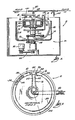
- FIG. 1 A centrifugal fluid processing system 10 embodying the features of the invention is shown in Fig. 1.
- the system 10 includes a centrifuge 12 and an associated fluid processing set 14.
- the set 14 is disposable, intended to be used once and then discarded.
- the system 10 can be used to process many different types of fluid. As will become apparent, the system 10 is capable of efficiently processing large volumes of fluid at relatively high flow rates. At the same time, the system 10 is well adapted to handle special fluids containing living cells or delicate organisms, such as blood or cultured cell suspensions, both on a clinical basis and an industrial basis. For this reason, the system 10 is particularly well suited for use in the medical field. For this reason, the system 10 will be described as being used in this particular environment.
- the centrifuge 12 can be variously constructed. However, in the illustrated embodiment, the centrifuge 12 is shown to incorporate the principles of operation disclosed in Adams U. S. Patent No. Re 29,738.
- the centrifuge 12 includes a processing assembly 16 and a rotor assembly 18 each of which independently rotates about the same axis 20.
- the processing assembly 16 is connected to a first drive shaft 22.
- the rotor assembly 18 is connected to a second drive shaft 28.
- the second drive shaft is driven via a suitable pulley assembly 24 by a drive motor 26.
- the first drive shaft 22 is driven by a suitable pulley assembly 30 associated with the second drive shaft 28.
- the pulley assemblies 24 and 30 are conventionally arranged to cause the processing assembly 16 to rotate in the same direction as and at twice the rotational speed of the rotor assembly 18. Examples of this type of construction are more fully disclosed in Lolachi U. 5. Patent 4,113,173.
- the processing assembly 16 includes an inner processing area 32.
- the processing area 32 takes the form of an arcuate slot or channel.
- the slot 32 can be configured in various ways, depending upon the intended use of the system. In the illustrated embodiment (best shown in Fig. 2), the slot 32 is generally equally radially spaced about the rotational axis 20 shared by processing assembly 16 and rotor assembly 18.
- the fluid processing set 14 includes an envelope or tube 34 defining a hollow interior chamber 36 having an inlet end 38 and an outlet end 40.
- the tube 34 is intended to be inserted into the processing slot 32 (see Figs. 1 and 2).
- the intended centrifugal separation of the processed fluid occurs within the interior chamber 36 of the tube 34 due to centrifugal forces created during rotation of the processing assembly 16.
- the tube 34 is can be made from either a flexible or rigid material. When flexible, the tube 34 can be readily fitted into the slot 32 to there conform to the particular configuration of the slot 32. When rigid, the tube 34 would be preformed to match the particular configuration of the slot 32. In the illustrated embodiment, which contemplates use of the system 10 in the medical field, the tube 34 is made from a flexible medical grade plastic material, such a polyvinyl chloride.
- the fluid processing set 14 further includes inlet tubing 42 for conveying fluid into the inlet end 38 of the tube chamber 36 for centrifugal separation.
- the set 14 includes outlet tubing 44 for conveying fluid constituents from the outlet end 40 of the tube chamber 36 after processing.
- inlet tubes 42 there are two inlet tubes 42 and three outlet tubes 44 (see Fig. 3).
- outlet tubes 44 see Fig. 3
- the number of tubes can vary according to the intended use and function of the system 10.
- the inlet and outlet tubing 42 and 44 are made from flexible medical grade plastic material and are joined to form a multiple lumen umbilicus 46.
- the umbilicus 46 is suspended from a point above and axially aligned with the rotational axis 20 of the centrifuge 12 by means of a clamp 48 attached to a support arm 50. From this point, the umbilicus 46 extends generally downwardly and radially outwardly, passing against a guide arm 52 carried by the rotor assembly 18. From there, the umbilicus 46 extends generally downwardly and radially inwardly and then upwardly through the hollow center of the drive shaft 22 into the processing assembly 16.
- This looping arrangement of the umbilicus 46 coupled with the differing rotational rates of the processing assembly 16 and the rotor assembly 18 as just described, prevents the umbilicus 46 from becoming twisted during operation of the centrifuge 12.
- the use of rotating seals between the fixed and rotating parts of the system 10 is thereby avoided. However, it should be appreciated that the invention is applicable for use in other types of centrifugal systems, including those employing rotating seals.
- the rotation of the processing assembly 16 will create a centrifugal force field F (see Fig. 2) effecting the contents of the tube chamber 36.
- This force field F will create a "High G Region” 54 and a “Low G Region” 56 within the chamber 36.
- the "High G Region 54" is located adjacent to the outer wall of the chamber 36, where the force field is farthest away from the rotational axis and the contents of the chamber 36 are subjected to the highest rotational (or "G") forces.
- the "Low G Region 56" is located adjacent to the inner wall of the chamber 36, where the force field is nearer to the rotational axis and the contents of the chamber are subjected to lesser rotational (or "G") forces. As best shown in Figs. 6 and 7, higher density materials present in the processed fluid (designated 101 in Figs. 6 and 7) will migrate under the influence of the force field F toward the High G Region 54, leaving the less dense materials and supernatant (designated 115 in Figs. 6 and 7) behind in the Low G Region 56.
- the fluid to be processed is introduced into the tube chamber 36 using a suitable in line pumping mechanism 58.
- the pumping mechanism takes the form of a peristaltic pump 58 situated upstream of the tube chamber 36.
- Fig. 8 the set 14 as just described is shown particularly configured for use to harvest TIL cells.
- cultured TIL cell solution filling approximately 70 to 260 three liter bags 60, each filled with about 1-1/2 liters of solution, is centrifugally processed to remove the supernatant and obtain concentrated TIL cells (which presently consists of approximately 2 x 10¹¹ cells occupying a volume which ranges between 220 to 400 ml).
- 5-lead and 10-lead manifold sets 62 are used to interconnect the many supply bags 60 to a single inlet line 64.
- the cultured cell fluid is then conveyed into a reservoir bag 66, using the supply pump 68, and then conducted into the tube 34, using the processing pump 58.
- the tube 34 is approximately 32 inches long and 3 inches wide.
- the interior surface area of the tube 34 is approximately 200 square inches.
- the TIL cells are separated from the culture medium (which constitutes the supernatant).
- the supernatant is collected in large volume containers 72.
- the concentrated TIL cells are transferred to a collection container 74 for administration to the patient.
- the invention provides a fluid processing system 10 that includes means 76 located adjacent the inlet end of the tube chamber 36 for directing incoming fluid away from the High G Region 54 and toward the Low G Region 56 of the chamber 36 in a generally uniform flow having reduced turbulence or being generally free of turbulence.
- the uniform flow constitutes a relatively thin stream filling the entire effective surface area of the Low G Region 56 adjacent to the inlet end of the chamber 36.
- the means 76 therefore establishes, upon the entry of high velo city fluid into the centrifugal field F, the desired flow conditions for effective separation.
- the means 76 also directs and dispenses the fluid in a manner that maximizes the effective surface area of the tube chamber 36 for separation. Due to the invention, effective separation can be achieved, even at high inlet flow rates.
- the means 76 can be variously constructed. One embodiment is shown in Figs. 3 to 5. In this arrangement, the means 76 is part of a port block assembly 78 situated within the inlet end 38 of the tube chamber 36.
- the assembly 78 includes top, bottom, and side walls 80; 81; and 82 defining an open interior 84.
- the assembly 78 also includes a first end wall 86 closing the adjacent end of the interior 84.
- One or more inlet ports 88 are formed on this end wall 86.
- the inlet tubing 42 is attached to these ports 88 to introduce fluid into the open interior 84 of the assembly 78.
- the means 76 comprises a partial second end wall 90 located on the end of the port block assembly 78 opposite to the end wall 86 on which the inlet ports 88 are situated.
- This partial end wall 90 extends from the top wall 80 toward the bottom wall 81, terminating a short distance therefrom to there define a flow passage 92 communicating with the open interior 84 of the assembly 78.
- fluid introduced into the open interior 84 of the port block assembly 78 (via the inlet ports 88) is directed into the centrifugal force field through the flow passage 92.
- the port block assembly 78 is situated within the inlet end of the tube chamber 36 with the flow passage 92 extending longitudinally across the entire interior surface of the tube chamber 36 which, in use, becomes the Low G Region 56.
- a guide key 94 is provided on the port block assembly 78 which mates with a groove 96 in the processing area 32 (see Fig 2) when the tube 34 is properly oriented.
- the system 10 further includes means 98 defining a region 100 for collecting high density materials within the tube chamber 36.
- the means 98 includes a dam assembly 102 situated within the tube chamber 36 downstream of the port block assembly 78.
- the dam assembly 102 may be variously constructed.
- the dam assembly 102 is part of another port block assembly as previously described.
- the assembly 102 includes top and bottom walls 103/104, side walls 105, and an end wall 106.
- the dam assembly 102 comprises a partial end wall 108, which like the means 76 associated with the port block assembly 78, forms another flow passage 110 through which fluid must pass to exit the tube chamber 36.
- the length of the end wall 108 associated with the dam assembly 102 can vary. It can be the same as or different than the end wall 90 of the port block assembly 78, depending upon the nature and type of collection area or areas sought to be established within the tube chamber 36.
- the sedementation of higher density materials in the region 100 is also effected by the fluid flow rate, the RPM of the centrifuge, and the interior thickness of the tube chamber 36. These variables can be adjusted to alter the collection characteristics of the tube 34.
- dam assemblies of varying lengths and spacing can be used to create multiple separation and sedimentation zones within the tube chamber 36.
- the higher density materials (designated 101 in Figs. 6 and 7) migrating toward the High G Region 54 of the chamber 36 will collect within the area 100 bounded by the partial end wall 90 of the port block assembly 78 and the partial end wall 108 of the dam assembly 102.
- the dam assembly 102 is located in the outlet end 40 of the tube chamber 36, and outlet ports 112 are accordingly formed on the end wall 106, as in the port block assembly 78.
- the dam assembly 102 can be located within the tube chamber 36 at a location upstream of the outlet end 40 of the chamber 36 (as shown in Fig. 6), in which case the end wall 106 would be free of ports.
- a separate port block assembly (not shown), without a partial end wall, would be used at the outlet end 40 of the tube chamber 36.
- the port block assembly 78 and the dam assembly 102 can be made of various materials. In the illustrated embodiment, both are injection molded plastic parts that are located and sealed within the confines of the tube chamber 36 by heat sealing, solvent sealing, or similar techniques.
- the dimensions of the flow passages 92 and 110 can vary according to the type of fluid being processed and the flow conditions desired. In the particular embodiment shown in Fig. 8, the flow passages 92 and 110 are each about 3 inches wide (the same width as the associated tube) and about .025 inch in height. The passages 92 and 110 therefore comprises restricted flow passages.
- the means 76 takes the form of a ridge 114 formed within the outside (High G) side of the processing area 32 of the assembly 16.
- the ridge 114 presses against the exterior of the outside wall of the tube 34, thereby forming a passage 92 like that formed by the partial end wall 90 of the port block assembly 78.
- a recess 116 is formed in the inside (Low G) side of the processing area 32 radially across from the ridge 114 to facilitate insertion and removal of the tube 34 and to better define the passage 92.
- the means 98 for defining the collection area 100 for higher density materials can also take the form of a ridge 118 and associated recess 120 formed along the walls of the processing area 32 of the centrifuge 12.
- FIGs. 6 and 7 A centrifugal processing method which embodies the features of the invention is shown in Figs. 6 and 7. This process will result by the operation of the above described port block assembly 78 and dam assembly 102 when the tube chamber 36 is exposed to the centrifugal field F. However, it should be appreciated that the process can be achieved by other means as well.
- the fluid to be processed is introduced into the centrifugal force field F, it is directed away from the region of the chamber 36 where the largest centrifugal (or "G") forces exist. Furthermore, the fluid is directed and dispensed into the force field as a generally uniform stream (designated by arrows and number 111 in Figs 6 and 7) having reduced turbulence of being essentially free of turbulence.
- incoming fluid entering the port block assembly 78 (via the ports 88) is immediately confined within the open interior 84. Turbulent flow conditions occasioned by the entry of fluid into the chamber 36 (indicated by swirling arrows 113 in Figs 6 and 7) are thereby effectively confined to this interior area 84 and isolated from the remainder of the tube chamber 36.
- the fluid confined within the interior area 84 is directed by the partial end wall 90 away from the High G Region 54 and out into the tube chamber 36 via the passage 92.
- the fluid is directed and dispensed in a generally uniform stream 111 extending across the Low G Region 56 of the tube chamber 36.
- the process also creates within the chamber 36 a region 100 where the higher density materials 101 collect, while allowing the supernatant 115 to flow freely out of the chamber 36.
- the higher density materials 101 migrating toward the High G Region 54 of the chamber 36 collect within the area 100 bounded by the partial end wall 90 of the port block assembly 78 and the partial end wall 108 of the dam assembly 102.
- the supernatant which is free of the higher density materials 101, passes through the passage 110 of the dam assembly 102 and exits the outlet end 40 of the tube chamber 36.
- a tube 34 embodying the features of the invention was used in association with a set as generally shown in Fig. 8 and an Adams-type centrifuge to harvest human red blood cells from a saline suspension. Three runs were conducted.
- the suspension had an original red blood cell concentration of 1.27 x 10⁷ per ml. This suspension was centrifugally processed through the tube at a flow rate of 1800 ml/min at 1600 RPM. During processing, concentrated red blood cells were collected at processing efficiency of 94.9%.
- the original suspension concentration was 1.43 x 10⁷ red blood cells per ml.
- concentrated red blood cells were collected at a processing efficiency of 95.7%.
- the original suspension concentration was 1.33 x 10⁷ red blood cells per ml.
- concentrated red blood cells were collected at a processing efficiency of 91.5%.
- a tube 34 embodying the features of the invention was used in association with a set as generally shown in Fig. 8 and an Adams-type centrifuge to harvest TIL cells from suspension.
- TIL cell viability of 73% was measured prior to processing. TIL cell viability of 73% was measured after processing.
- Lytic activity of the TIL cells prior to processing was 5.4%. After processing, the lytic activity was 4.3%, which does not constitute a statistically significant difference.
- Example 2 further demonstrates that processing occurs without biological damage to the cellular components.
Abstract
Description
- The invention generally relates to systems and methods for separating fluids by centrifugation. More particularly, the invention relates to the centrifugation of large volumes of fluids at relatively high flow rates. In this respect, the invention also relates to systems and methods particularly well suited for the processing of cultured cells and supernatant, such as in the fields of biotechnology and adoptive immunotherapy.
- Many fluid processing techniques entail the centrifugation of large volumes of fluids. To minimize processing times, these techniques often require the use of relatively high flow rates. Increasingly, such techniques are being used in the medical field.
- For example, in the areas of biotechnology and adoptive immunotherapy, it is necessary to process relatively large volumes of cultured cellular products by centrifugation. Through centrifugation, cultured cells are separated from the supernatant for the purpose of replacing/exchanging the culture medium; or for providing a cell-free supernatant for the subsequent collection of antibodies or for subsequent use as an additive to culture medium; or for the collection of concentrated cellular product.
- In the area of adoptive immunotherapy, it has been possible to process between 10 to 50 liters of cultured LAK (Limphokine Activated Killer) cells at a rate of 175 ml/min using conventional centrifugation techniques and devices previously used in whole blood processing. However, in the processing of TIL (Tumor Infiltrating Lymphocytes), the volume of cultured cells that must be processed is increased by an order of magnitude to approximately 100 to 400 liters. Conventional blood processing techniques and devices cannot effectively deal with these large fluid volumes and the attendant need to increase the processing rates.
- Furthermore, the necessarily high inlet flow rates can lead to confused, turbulent flow conditions within the centrifugation chamber. These flow conditions are not desireable, because they can interfere with sedimentation and separation within the centrifugal force field. Thus, despite the high inlet flow rates, the overall effectiveness and efficiency of the process suffers.
- High inlet flow rates and resulting confused, turbulent flow conditions can also result in a non-uniform distribution of the fluid within the centrifugation chamber.
- Often, then, it is necessary to reduce the inlet flow rate below the desired amount in the interest of obtaining the flow conditions within the processing chamber conducive to optimal separation.
- The invention provides systems and methods for centrifugally processing large volumes of fluid at relatively high flow rates without sacrificing separation efficiencies or damaging the end product.
- In one aspect, the invention provides a centrifugal processing system and method in which a centrifugal force field is developed within a chamber. As the fluid to be processed is introduced into the chamber, it is directed away from the region of the chamber where the largest centrifugal (or "G") forces exist. The fluid is also preferably conveyed into the force field in a generally uniform stream. As used herein, the term "generally uniform" describes a flow condition in which turbulence is reduced or eliminated to the fullest extent possible.
- In accordance with this aspect of the invention, the system and method establish, upon the entry of high velocity fluid into the centrifugal field, generally uniform flow conditions conducive to effective separation. The system and method also direct the fluid in a way that maximizes the effective surface area of the centrifugation chamber for separation. Effective separation can thereby be achieved at high inlet flow rates.
- Preferably, the system and method embodying the features of the invention also create within the chamber a region where the higher density materials collect, while allowing the supernatant to freely flow out of the chamber.
- In another aspect of the invention, the centrifugation chamber takes the form of a tube or envelope. In this embodiment, a passage is formed within the tube adjacent to its inlet end. All fluid entering the tube is directed through this passage and into the centrifugal force field. The passage creates a generally uniform stream of fluid having reduced turbulence or being essentially free of turbulence. This stream is directed and dispensed uniformly into the region of the tube where the least centrifugal forces exist.
- Other features and advantages of the invention will become apparent upon considering the accompanying drawings, description, and claims.
-
- Fig. 1 is a schematic side view, fragmented and partially in section, of a centrifugal processing system embodying the features of the invention;
- Fig. 2 is a top view of the centrifugal processing system taken generally along line 2-2 in Fig. 1;
- Fig. 3 is an enlarged fragmented top view of the processing tube or envelope of the fluid processing set associated with the system shown in Fig. 1;
- Fig. 4 is a side view of the processing tube or envelope taken generally along line 4-4 in Fig. 3;
- Fig. 5 is an exploded perspective view of the processing tube shown in Fig. 3 showing the associated flow control means;
- Fig. 6 is an enlarged schematic view, fragmented and broken away in section, of the processing tube or envelope shown in Figs. 3 to 5 illustrating the flow of fluid through the tube or envelope when it is in use in a centrifugal field;
- Fig. 7 is a greatly enlarged schematic view, fragmented and in section, of the collection of higher density materials in the tube or envelope shown in Fig. 6;
- Fig. 8 is a centrifugal fluid processing system embodying the features of the invention and intended to be use in the harvesting of cell cultures on a large volume basis; and
- Fig. 9 is an alternate embodiment of a centrifugal fluid processing system embodying the features of the invention.
- A centrifugal
fluid processing system 10 embodying the features of the invention is shown in Fig. 1. Thesystem 10 includes acentrifuge 12 and an associated fluid processing set 14. In the illustrated and preferred embodiment, theset 14 is disposable, intended to be used once and then discarded. - The
system 10 can be used to process many different types of fluid. As will become apparent, thesystem 10 is capable of efficiently processing large volumes of fluid at relatively high flow rates. At the same time, thesystem 10 is well adapted to handle special fluids containing living cells or delicate organisms, such as blood or cultured cell suspensions, both on a clinical basis and an industrial basis. For this reason, thesystem 10 is particularly well suited for use in the medical field. For this reason, thesystem 10 will be described as being used in this particular environment. - The
centrifuge 12 can be variously constructed. However, in the illustrated embodiment, thecentrifuge 12 is shown to incorporate the principles of operation disclosed in Adams U. S. Patent No. Re 29,738. - In this arrangement (as best shown in Fig. 1), the
centrifuge 12 includes a processing assembly 16 and a rotor assembly 18 each of which independently rotates about the same axis 20. The processing assembly 16 is connected to afirst drive shaft 22. The rotor assembly 18 is connected to asecond drive shaft 28. The second drive shaft is driven via asuitable pulley assembly 24 by adrive motor 26. Thefirst drive shaft 22 is driven by a suitable pulley assembly 30 associated with thesecond drive shaft 28. - The
pulley assemblies 24 and 30 are conventionally arranged to cause the processing assembly 16 to rotate in the same direction as and at twice the rotational speed of the rotor assembly 18. Examples of this type of construction are more fully disclosed in Lolachi U. 5. Patent 4,113,173. - As can be best seen in Figs. 1 and 2, the processing assembly 16 includes an
inner processing area 32. Theprocessing area 32 takes the form of an arcuate slot or channel. Theslot 32 can be configured in various ways, depending upon the intended use of the system. In the illustrated embodiment (best shown in Fig. 2), theslot 32 is generally equally radially spaced about the rotational axis 20 shared by processing assembly 16 and rotor assembly 18. - With further reference now to Figs. 3 to 5, the fluid processing set 14 includes an envelope or
tube 34 defining a hollowinterior chamber 36 having aninlet end 38 and anoutlet end 40. Thetube 34 is intended to be inserted into the processing slot 32 (see Figs. 1 and 2). As will be soon described in greater detail below, the intended centrifugal separation of the processed fluid occurs within theinterior chamber 36 of thetube 34 due to centrifugal forces created during rotation of the processing assembly 16. - The
tube 34 is can be made from either a flexible or rigid material. When flexible, thetube 34 can be readily fitted into theslot 32 to there conform to the particular configuration of theslot 32. When rigid, thetube 34 would be preformed to match the particular configuration of theslot 32. In the illustrated embodiment, which contemplates use of thesystem 10 in the medical field, thetube 34 is made from a flexible medical grade plastic material, such a polyvinyl chloride. - As best shown in Fig. 1, the fluid processing set 14 further includes
inlet tubing 42 for conveying fluid into theinlet end 38 of thetube chamber 36 for centrifugal separation. Likewise, theset 14 includesoutlet tubing 44 for conveying fluid constituents from the outlet end 40 of thetube chamber 36 after processing. - In the illustrated embodiment, there are two
inlet tubes 42 and three outlet tubes 44 (see Fig. 3). Of course, the number of tubes can vary according to the intended use and function of thesystem 10. - In the illustrated embodiment, the inlet and
outlet tubing multiple lumen umbilicus 46. As best shown in Fig. 1, theumbilicus 46 is suspended from a point above and axially aligned with the rotational axis 20 of thecentrifuge 12 by means of aclamp 48 attached to a support arm 50. From this point, theumbilicus 46 extends generally downwardly and radially outwardly, passing against a guide arm 52 carried by the rotor assembly 18. From there, theumbilicus 46 extends generally downwardly and radially inwardly and then upwardly through the hollow center of thedrive shaft 22 into the processing assembly 16. - This looping arrangement of the
umbilicus 46, coupled with the differing rotational rates of the processing assembly 16 and the rotor assembly 18 as just described, prevents the umbilicus 46 from becoming twisted during operation of thecentrifuge 12. The use of rotating seals between the fixed and rotating parts of thesystem 10 is thereby avoided. However, it should be appreciated that the invention is applicable for use in other types of centrifugal systems, including those employing rotating seals. - Once the
tube 34 is located in theprocessing area 32 and filled with fluid, the rotation of the processing assembly 16 will create a centrifugal force field F (see Fig. 2) effecting the contents of thetube chamber 36. This force field F will create a "High G Region" 54 and a "Low G Region" 56 within thechamber 36. As shown in Fig. 2, the "High G Region 54" is located adjacent to the outer wall of thechamber 36, where the force field is farthest away from the rotational axis and the contents of thechamber 36 are subjected to the highest rotational (or "G") forces. The "Low G Region 56" is located adjacent to the inner wall of thechamber 36, where the force field is nearer to the rotational axis and the contents of the chamber are subjected to lesser rotational (or "G") forces. As best shown in Figs. 6 and 7, higher density materials present in the processed fluid (designated 101 in Figs. 6 and 7) will migrate under the influence of the force field F toward theHigh G Region 54, leaving the less dense materials and supernatant (designated 115 in Figs. 6 and 7) behind in theLow G Region 56. - To obtained the desired flow rate conditions, the fluid to be processed is introduced into the
tube chamber 36 using a suitable in line pumping mechanism 58. In the illustrated embodiment (see Fig. 1), the pumping mechanism takes the form of a peristaltic pump 58 situated upstream of thetube chamber 36. - In Fig. 8, the
set 14 as just described is shown particularly configured for use to harvest TIL cells. In this procedure, cultured TIL cell solution filling approximately 70 to 260 threeliter bags 60, each filled with about 1-1/2 liters of solution, is centrifugally processed to remove the supernatant and obtain concentrated TIL cells (which presently consists of approximately 2 x 10¹¹ cells occupying a volume which ranges between 220 to 400 ml). - In this arrangement 5-lead and 10-lead manifold sets 62 are used to interconnect the
many supply bags 60 to asingle inlet line 64. The cultured cell fluid is then conveyed into a reservoir bag 66, using the supply pump 68, and then conducted into thetube 34, using the processing pump 58. - In this arrangement, the
tube 34 is approximately 32 inches long and 3 inches wide. The interior surface area of thetube 34 is approximately 200 square inches. - During centrifugation, the TIL cells are separated from the culture medium (which constitutes the supernatant). The supernatant is collected in
large volume containers 72. Afterwards, the concentrated TIL cells are transferred to acollection container 74 for administration to the patient. - In this and other applications, where relatively large volumes of fluid are to be processed, it is desirable to maximize the inlet flow rate of the fluid, as this will shorten the overall processing time. In the case of a TIL procedure, a nominal processing rate of at least 1.5 liters per minute is attained. However, with the
system 10 illustrated, it is believed that the processing rate can be increased upwards to about 4 liters per minute. This rate is significantly higher than the nominal processing rates conventionally used for blood processing (about 50 ml/min) or conventionally used for TIL cell harvesting (about 175 ml/min). - Use of these relatively high inlet flow rates can pose processing problems. In particular, such high rates can lead to confused, turbulent flow conditions within the
tube chamber 36. These turbulent or otherwise confused, non-uniform flow conditions can interfere with sedimentation and separation within the centrifugal force field F, lowering the overall effectiveness and efficiency of the process. - High inlet flow rates and attendant confused, turbulent flow conditions can also result in a non-uniform distribution of the fluid within the
tube chamber 36. To maximize the effective surface area along which separation occurs, the incoming fluid should preferably enter in theLow G Region 56 as soon as possible after entering thetube 34. The fluid components are thereby exposed to the full extent of the centrifugal force field F for the longest period of time. However, high inlet flow rates can spray or disperse the incoming fluid indiscriminately into both the High andLow G Regions tube 34. This, too, lowers the overall effectiveness and efficiency of the process. - To optimize the effectiveness of separation at high inlet flow rates, the invention provides a
fluid processing system 10 that includes means 76 located adjacent the inlet end of thetube chamber 36 for directing incoming fluid away from theHigh G Region 54 and toward theLow G Region 56 of thechamber 36 in a generally uniform flow having reduced turbulence or being generally free of turbulence. Preferably, the uniform flow constitutes a relatively thin stream filling the entire effective surface area of theLow G Region 56 adjacent to the inlet end of thechamber 36. - In accordance with the invention, the
means 76 therefore establishes, upon the entry of high velo city fluid into the centrifugal field F, the desired flow conditions for effective separation. The means 76 also directs and dispenses the fluid in a manner that maximizes the effective surface area of thetube chamber 36 for separation. Due to the invention, effective separation can be achieved, even at high inlet flow rates. - The means 76 can be variously constructed. One embodiment is shown in Figs. 3 to 5. In this arrangement, the
means 76 is part of aport block assembly 78 situated within theinlet end 38 of thetube chamber 36. Theassembly 78 includes top, bottom, andside walls 80; 81; and 82 defining anopen interior 84. Theassembly 78 also includes afirst end wall 86 closing the adjacent end of the interior 84. One ormore inlet ports 88 are formed on thisend wall 86. Theinlet tubing 42 is attached to theseports 88 to introduce fluid into theopen interior 84 of theassembly 78. - In this arrangement, the
means 76 comprises a partialsecond end wall 90 located on the end of theport block assembly 78 opposite to theend wall 86 on which theinlet ports 88 are situated. Thispartial end wall 90 extends from thetop wall 80 toward thebottom wall 81, terminating a short distance therefrom to there define aflow passage 92 communicating with theopen interior 84 of theassembly 78. As will be described in greater detail below, fluid introduced into theopen interior 84 of the port block assembly 78 (via the inlet ports 88) is directed into the centrifugal force field through theflow passage 92. - As best shown in Fig. 4, the
port block assembly 78 is situated within the inlet end of thetube chamber 36 with theflow passage 92 extending longitudinally across the entire interior surface of thetube chamber 36 which, in use, becomes theLow G Region 56. - To assure that the interior surface of the
tube 34 becomes theLow G Region 56 when situated within theprocessing area 32, aguide key 94 is provided on theport block assembly 78 which mates with a groove 96 in the processing area 32 (see Fig 2) when thetube 34 is properly oriented. - The
system 10 further includesmeans 98 defining aregion 100 for collecting high density materials within thetube chamber 36. In the embodiment shown in Figs. 2 to 5, themeans 98 includes adam assembly 102 situated within thetube chamber 36 downstream of theport block assembly 78. Thedam assembly 102 may be variously constructed. In the illustrated embodiment, thedam assembly 102 is part of another port block assembly as previously described. Theassembly 102 includes top andbottom walls 103/104,side walls 105, and anend wall 106. - In this arrangement, the
dam assembly 102 comprises apartial end wall 108, which like themeans 76 associated with theport block assembly 78, forms anotherflow passage 110 through which fluid must pass to exit thetube chamber 36. - The length of the
end wall 108 associated with thedam assembly 102 can vary. It can be the same as or different than theend wall 90 of theport block assembly 78, depending upon the nature and type of collection area or areas sought to be established within thetube chamber 36. The sedementation of higher density materials in theregion 100 is also effected by the fluid flow rate, the RPM of the centrifuge, and the interior thickness of thetube chamber 36. These variables can be adjusted to alter the collection characteristics of thetube 34. - It should also be appreciated that multiple dam assemblies of varying lengths and spacing can be used to create multiple separation and sedimentation zones within the
tube chamber 36. - As shown in Figs. 6 and 7, and as will be described in greater detail below, the higher density materials (designated 101 in Figs. 6 and 7) migrating toward the
High G Region 54 of thechamber 36 will collect within thearea 100 bounded by thepartial end wall 90 of theport block assembly 78 and thepartial end wall 108 of thedam assembly 102. - In the embodiment shown in Figs. 3 to 5, the
dam assembly 102 is located in the outlet end 40 of thetube chamber 36, andoutlet ports 112 are accordingly formed on theend wall 106, as in theport block assembly 78. However, it should be appreciated that thedam assembly 102 can be located within thetube chamber 36 at a location upstream of the outlet end 40 of the chamber 36 (as shown in Fig. 6), in which case theend wall 106 would be free of ports. In this arrangement, a separate port block assembly (not shown), without a partial end wall, would be used at the outlet end 40 of thetube chamber 36. - The
port block assembly 78 and thedam assembly 102 can be made of various materials. In the illustrated embodiment, both are injection molded plastic parts that are located and sealed within the confines of thetube chamber 36 by heat sealing, solvent sealing, or similar techniques. - The dimensions of the
flow passages flow passages passages - Another embodiment of the
means 76 for directing incoming fluid toward theLow G Region 56 is shown in Fig. 9. In this arrangement, themeans 76 takes the form of a ridge 114 formed within the outside (High G) side of theprocessing area 32 of the assembly 16. When thetube 34 is positioned within the processing area 32 (as shown in Fig. 7), the ridge 114 presses against the exterior of the outside wall of thetube 34, thereby forming apassage 92 like that formed by thepartial end wall 90 of theport block assembly 78. Preferably, arecess 116 is formed in the inside (Low G) side of theprocessing area 32 radially across from the ridge 114 to facilitate insertion and removal of thetube 34 and to better define thepassage 92. - As also shown in Fig. 9, the
means 98 for defining thecollection area 100 for higher density materials can also take the form of aridge 118 and associatedrecess 120 formed along the walls of theprocessing area 32 of thecentrifuge 12. - A centrifugal processing method which embodies the features of the invention is shown in Figs. 6 and 7. This process will result by the operation of the above described
port block assembly 78 anddam assembly 102 when thetube chamber 36 is exposed to the centrifugal field F. However, it should be appreciated that the process can be achieved by other means as well. - In this method, as the fluid to be processed is introduced into the centrifugal force field F, it is directed away from the region of the
chamber 36 where the largest centrifugal (or "G") forces exist. Furthermore, the fluid is directed and dispensed into the force field as a generally uniform stream (designated by arrows and number 111 in Figs 6 and 7) having reduced turbulence of being essentially free of turbulence. - Referring specifically now to Figs. 6 and 7, incoming fluid entering the port block assembly 78 (via the ports 88) is immediately confined within the
open interior 84. Turbulent flow conditions occasioned by the entry of fluid into the chamber 36 (indicated by swirlingarrows 113 in Figs 6 and 7) are thereby effectively confined to thisinterior area 84 and isolated from the remainder of thetube chamber 36. - The fluid confined within the
interior area 84 is directed by thepartial end wall 90 away from theHigh G Region 54 and out into thetube chamber 36 via thepassage 92. By virtue of the shape of thepassage 92, the fluid is directed and dispensed in a generally uniform stream 111 extending across theLow G Region 56 of thetube chamber 36. - Optimal conditions for sedimentation and separation are thereby quickly established. As a result, the
higher density materials 101 migrate due to the force field F toward theHigh G Region 54. The remaining supernatant (designated by arrows andnumber 115 in Figs. 6 and 7) continues to flow uniformly along theLow G Region 56 toward the outlet end 40 of thetube chamber 36. - The process also creates within the chamber 36 a
region 100 where thehigher density materials 101 collect, while allowing the supernatant 115 to flow freely out of thechamber 36. As can be best seen in Fig. 6, thehigher density materials 101 migrating toward theHigh G Region 54 of thechamber 36 collect within thearea 100 bounded by thepartial end wall 90 of theport block assembly 78 and thepartial end wall 108 of thedam assembly 102. At the same time, the supernatant, which is free of thehigher density materials 101, passes through thepassage 110 of thedam assembly 102 and exits the outlet end 40 of thetube chamber 36. - A
tube 34 embodying the features of the invention was used in association with a set as generally shown in Fig. 8 and an Adams-type centrifuge to harvest human red blood cells from a saline suspension. Three runs were conducted. - In the first run, the suspension had an original red blood cell concentration of 1.27 x 10⁷ per ml. This suspension was centrifugally processed through the tube at a flow rate of 1800 ml/min at 1600 RPM. During processing, concentrated red blood cells were collected at processing efficiency of 94.9%.
- In the second run, the original suspension concentration was 1.43 x 10⁷ red blood cells per ml. During centrifugal processing at a flow rate of 1000 ml/min at 1600 RPM, concentrated red blood cells were collected at a processing efficiency of 95.7%.
- In the third run, the original suspension concentration was 1.33 x 10⁷ red blood cells per ml. During centrifugal processing at a flow rate of 1800 ml/min at 1600 RPM, concentrated red blood cells were collected at a processing efficiency of 91.5%.
- A
tube 34 embodying the features of the invention was used in association with a set as generally shown in Fig. 8 and an Adams-type centrifuge to harvest TIL cells from suspension. - During the procedure, 24,559 ml of cultured TIL cell suspension was processed through the tube a flow rates varying between 500 to 1500 ml/min at 1600 RPM. 445 ml of concentrated TIL cells were obtained.
- Approximately 564.9 x 10⁸ TIL cells were contained in the suspension prior to processing. During processing, approximately 462.8 x 10⁸ TIL cells were collected, for a processing efficiency of 82%.
- TIL cell viability of 73% was measured prior to processing. TIL cell viability of 73% was measured after processing.
- Lytic activity of the TIL cells prior to processing was 5.4%. After processing, the lytic activity was 4.3%, which does not constitute a statistically significant difference.
- The foregoing examples clearly illustrate the ability of a processing system made and operated in accordance with the invention to efficiently process large volumes of cellular suspensions at relatively high fluid flow rates. Example 2 further demonstrates that processing occurs without biological damage to the cellular components.
- Various features of the invention are set forth in the following claims.
Claims (9)
developing a centrifugal force field within a chamber;
introducing the fluid to be processed into the chamber; and
dispensing the incoming fluid as a generally uniform stream directed away from the region of the chamber where the largest centrifugal forces are developed.
creating within the chamber a region confining the higher density components separated within the centrifugal field while allowing the remaining components of the fluid to flow out of the chamber.
means for developing a centrifugal force field within a chamber;
means for introducing the fluid to be processed into the chamber;
means for dispensing the incoming fluid as a generally uniform stream directed away from the region of the chamber where the largest centrifugal forces are developed.
means for creating within the chamber a region confining the higher density components separated within the centrifugal field while allowing the remaining components of the fluid to flow out of the chamber.
wherein said chamber comprises a tube having an inlet end and an outlet end; and
wherein said directing means comprises means forming a passage the tube adjacent to its inlet end for dispensing a uniform stream of fluid into the region of the tube where the least centrifugal forces exist.
a body having an inlet end and an outlet end and defining an interior chamber;
means for conveying the fluid into said chamber through said inlet end; and
means for dispensing the incoming fluid as a generally uniform stream directed away from the region of the chamber where, in response to exposure to a centrifugal field, the largest centrifugal forces are developed.
means for creating within the chamber a region confining the higher density components separated in response to the centrifugal field while allowing the remaining components of the fluid to flow out of the outlet end of said chamber.
wherein said directing means comprises means forming a passage said body adjacent to its inlet end for dispensing a uniform stream of fluid into the region of the chamber where, in response to exposure to a centrifugal field, the least centrifugal forces exist.
Applications Claiming Priority (2)
| Application Number | Priority Date | Filing Date | Title |
|---|---|---|---|
| US25512788A | 1988-10-07 | 1988-10-07 | |
| US255127 | 1988-10-07 |
Publications (3)
| Publication Number | Publication Date |
|---|---|
| EP0363120A2 true EP0363120A2 (en) | 1990-04-11 |
| EP0363120A3 EP0363120A3 (en) | 1991-01-23 |
| EP0363120B1 EP0363120B1 (en) | 1993-11-24 |
Family
ID=22966947
Family Applications (1)
| Application Number | Title | Priority Date | Filing Date |
|---|---|---|---|
| EP19890310048 Expired - Lifetime EP0363120B1 (en) | 1988-10-07 | 1989-10-02 | Centrifugal fluid processing system and method |
Country Status (4)
| Country | Link |
|---|---|
| EP (1) | EP0363120B1 (en) |
| JP (1) | JP2967280B2 (en) |
| CA (1) | CA1334189C (en) |
| DE (2) | DE68910928T2 (en) |
Cited By (7)
| Publication number | Priority date | Publication date | Assignee | Title |
|---|---|---|---|---|
| WO1991015300A1 (en) * | 1990-04-02 | 1991-10-17 | Omega Teknik Hb | Centrifuge adapted for continuous through flow |
| EP0526869A1 (en) * | 1991-08-05 | 1993-02-10 | DIDECO S.p.A. | Multiple-duct tube for centrifugal blood separators and method of making the same |
| WO1997043045A1 (en) * | 1996-05-15 | 1997-11-20 | Cobe Laboratories, Inc. | Method and apparatus for reducing turbulence in fluid flow |
| US5792038A (en) * | 1996-05-15 | 1998-08-11 | Cobe Laboratories, Inc. | Centrifugal separation device for providing a substantially coriolis-free pathway |
| US5904645A (en) * | 1996-05-15 | 1999-05-18 | Cobe Laboratories | Apparatus for reducing turbulence in fluid flow |
| US6053856A (en) * | 1995-04-18 | 2000-04-25 | Cobe Laboratories | Tubing set apparatus and method for separation of fluid components |
| US6511411B1 (en) * | 1987-01-30 | 2003-01-28 | Baxter International Inc. | Compact enhanced yield blood processing systems |
Families Citing this family (4)
| Publication number | Priority date | Publication date | Assignee | Title |
|---|---|---|---|---|
| US6334842B1 (en) | 1999-03-16 | 2002-01-01 | Gambro, Inc. | Centrifugal separation apparatus and method for separating fluid components |
| US6354986B1 (en) | 2000-02-16 | 2002-03-12 | Gambro, Inc. | Reverse-flow chamber purging during centrifugal separation |
| CA2642653A1 (en) | 2002-04-16 | 2003-10-30 | Gambro Bct, Inc. | Blood component processing system, apparatus and method |
| EP2956187B1 (en) | 2013-02-18 | 2017-11-01 | Terumo BCT, Inc. | System for blood separation with a separation chamber having an internal gravity valve |
Citations (3)
| Publication number | Priority date | Publication date | Assignee | Title |
|---|---|---|---|---|
| US2662687A (en) * | 1950-04-01 | 1953-12-15 | Laval Separator Co De | Centrifugal separator for cold milk products and the like |
| US4091989A (en) * | 1977-01-04 | 1978-05-30 | Schlutz Charles A | Continuous flow fractionation and separation device and method |
| EP0261468A2 (en) * | 1986-09-24 | 1988-03-30 | Fresenius AG | Arrangement for a centrifuge |
-
1989
- 1989-09-27 CA CA 613606 patent/CA1334189C/en not_active Expired - Fee Related
- 1989-10-02 EP EP19890310048 patent/EP0363120B1/en not_active Expired - Lifetime
- 1989-10-02 DE DE1989610928 patent/DE68910928T2/en not_active Expired - Fee Related
- 1989-10-02 DE DE1989310048 patent/DE363120T1/en active Pending
- 1989-10-05 JP JP1261216A patent/JP2967280B2/en not_active Expired - Fee Related
Patent Citations (3)
| Publication number | Priority date | Publication date | Assignee | Title |
|---|---|---|---|---|
| US2662687A (en) * | 1950-04-01 | 1953-12-15 | Laval Separator Co De | Centrifugal separator for cold milk products and the like |
| US4091989A (en) * | 1977-01-04 | 1978-05-30 | Schlutz Charles A | Continuous flow fractionation and separation device and method |
| EP0261468A2 (en) * | 1986-09-24 | 1988-03-30 | Fresenius AG | Arrangement for a centrifuge |
Cited By (9)
| Publication number | Priority date | Publication date | Assignee | Title |
|---|---|---|---|---|
| US6511411B1 (en) * | 1987-01-30 | 2003-01-28 | Baxter International Inc. | Compact enhanced yield blood processing systems |
| WO1991015300A1 (en) * | 1990-04-02 | 1991-10-17 | Omega Teknik Hb | Centrifuge adapted for continuous through flow |
| EP0526869A1 (en) * | 1991-08-05 | 1993-02-10 | DIDECO S.p.A. | Multiple-duct tube for centrifugal blood separators and method of making the same |
| US5501840A (en) * | 1991-08-05 | 1996-03-26 | Dideco S.R.L. | Multilumen tubing for centrifugal blood separator |
| US6053856A (en) * | 1995-04-18 | 2000-04-25 | Cobe Laboratories | Tubing set apparatus and method for separation of fluid components |
| WO1997043045A1 (en) * | 1996-05-15 | 1997-11-20 | Cobe Laboratories, Inc. | Method and apparatus for reducing turbulence in fluid flow |
| US5792038A (en) * | 1996-05-15 | 1998-08-11 | Cobe Laboratories, Inc. | Centrifugal separation device for providing a substantially coriolis-free pathway |
| US5904645A (en) * | 1996-05-15 | 1999-05-18 | Cobe Laboratories | Apparatus for reducing turbulence in fluid flow |
| US5954626A (en) * | 1996-05-15 | 1999-09-21 | Cobe Laboratories, Inc. | Method of minimizing coriolis effects in a centrifugal separation channel |
Also Published As
| Publication number | Publication date |
|---|---|
| DE363120T1 (en) | 1990-09-06 |
| EP0363120A3 (en) | 1991-01-23 |
| JP2967280B2 (en) | 1999-10-25 |
| JPH02172546A (en) | 1990-07-04 |
| DE68910928D1 (en) | 1994-01-05 |
| EP0363120B1 (en) | 1993-11-24 |
| CA1334189C (en) | 1995-01-31 |
| DE68910928T2 (en) | 1994-06-30 |
Similar Documents
| Publication | Publication Date | Title |
|---|---|---|
| US5078671A (en) | Centrifugal fluid processing system and method | |
| US4936820A (en) | High volume centrifugal fluid processing system and method for cultured cell suspensions and the like | |
| US4146172A (en) | Centrifugal liquid processing system | |
| EP0194271B1 (en) | Closed hemapheresis system | |
| US4636193A (en) | Disposable centrifugal blood processing system | |
| EP1714702B1 (en) | Apparatus for separation of fluid components | |
| EP1854545B1 (en) | Centrifugal separation apparatus for separating fluid components | |
| US4734089A (en) | Centrifugal blood processing system | |
| US5224921A (en) | Small volume collection chamber | |
| US7918350B2 (en) | Separation apparatus and method | |
| AU702151B2 (en) | Particle separation apparatus and method | |
| EP0096217A2 (en) | Centrifuge assembly | |
| EP0664159A1 (en) | Plural collector centrifuge bowl for blood processing | |
| EP0765687A1 (en) | Method for centrifugal blood processing | |
| EP0363120A2 (en) | Centrifugal fluid processing system and method | |
| JPS61501494A (en) | Equipment for separating substances from suspensions | |
| EP0363119A2 (en) | High volume centrifugal fluid processing system and method for cultured cell suspensions | |
| JP2003093922A (en) | Centrifugal separation bowl |
Legal Events
| Date | Code | Title | Description |
|---|---|---|---|
| PUAI | Public reference made under article 153(3) epc to a published international application that has entered the european phase |
Free format text: ORIGINAL CODE: 0009012 |
|
| AK | Designated contracting states |
Kind code of ref document: A2 Designated state(s): BE DE FR GB IT |
|
| DET | De: translation of patent claims | ||
| PUAL | Search report despatched |
Free format text: ORIGINAL CODE: 0009013 |
|
| AK | Designated contracting states |
Kind code of ref document: A3 Designated state(s): BE DE FR GB IT |
|
| 17P | Request for examination filed |
Effective date: 19910315 |
|
| 17Q | First examination report despatched |
Effective date: 19920507 |
|
| GRAA | (expected) grant |
Free format text: ORIGINAL CODE: 0009210 |
|
| AK | Designated contracting states |
Kind code of ref document: B1 Designated state(s): BE DE FR GB IT |
|
| REF | Corresponds to: |
Ref document number: 68910928 Country of ref document: DE Date of ref document: 19940105 |
|
| ITF | It: translation for a ep patent filed |
Owner name: MODIANO & ASSOCIATI S.R.L. |
|
| ET | Fr: translation filed | ||
| PLBE | No opposition filed within time limit |
Free format text: ORIGINAL CODE: 0009261 |
|
| STAA | Information on the status of an ep patent application or granted ep patent |
Free format text: STATUS: NO OPPOSITION FILED WITHIN TIME LIMIT |
|
| 26N | No opposition filed | ||
| REG | Reference to a national code |
Ref country code: GB Ref legal event code: IF02 |
|
| PGFP | Annual fee paid to national office [announced via postgrant information from national office to epo] |
Ref country code: FR Payment date: 20020918 Year of fee payment: 14 |
|
| PGFP | Annual fee paid to national office [announced via postgrant information from national office to epo] |
Ref country code: GB Payment date: 20020927 Year of fee payment: 14 |
|
| PGFP | Annual fee paid to national office [announced via postgrant information from national office to epo] |
Ref country code: BE Payment date: 20021023 Year of fee payment: 14 |
|
| PGFP | Annual fee paid to national office [announced via postgrant information from national office to epo] |
Ref country code: DE Payment date: 20021031 Year of fee payment: 14 |
|
| PG25 | Lapsed in a contracting state [announced via postgrant information from national office to epo] |
Ref country code: GB Free format text: LAPSE BECAUSE OF NON-PAYMENT OF DUE FEES Effective date: 20031002 |
|
| PG25 | Lapsed in a contracting state [announced via postgrant information from national office to epo] |
Ref country code: BE Free format text: LAPSE BECAUSE OF NON-PAYMENT OF DUE FEES Effective date: 20031031 |
|
| BERE | Be: lapsed |
Owner name: *BAXTER INTERNATIONAL INC. Effective date: 20031031 |
|
| PG25 | Lapsed in a contracting state [announced via postgrant information from national office to epo] |
Ref country code: DE Free format text: LAPSE BECAUSE OF NON-PAYMENT OF DUE FEES Effective date: 20040501 |
|
| GBPC | Gb: european patent ceased through non-payment of renewal fee |
Effective date: 20031002 |
|
| PG25 | Lapsed in a contracting state [announced via postgrant information from national office to epo] |
Ref country code: FR Free format text: LAPSE BECAUSE OF NON-PAYMENT OF DUE FEES Effective date: 20040630 |
|
| REG | Reference to a national code |
Ref country code: FR Ref legal event code: ST |
|
| PG25 | Lapsed in a contracting state [announced via postgrant information from national office to epo] |
Ref country code: IT Free format text: LAPSE BECAUSE OF NON-PAYMENT OF DUE FEES;WARNING: LAPSES OF ITALIAN PATENTS WITH EFFECTIVE DATE BEFORE 2007 MAY HAVE OCCURRED AT ANY TIME BEFORE 2007. THE CORRECT EFFECTIVE DATE MAY BE DIFFERENT FROM THE ONE RECORDED. Effective date: 20051002 |