EP0364172A2 - Error detection and correction for a data storage system - Google Patents
Error detection and correction for a data storage system Download PDFInfo
- Publication number
- EP0364172A2 EP0364172A2 EP89310257A EP89310257A EP0364172A2 EP 0364172 A2 EP0364172 A2 EP 0364172A2 EP 89310257 A EP89310257 A EP 89310257A EP 89310257 A EP89310257 A EP 89310257A EP 0364172 A2 EP0364172 A2 EP 0364172A2
- Authority
- EP
- European Patent Office
- Prior art keywords
- polynomial
- error
- sector
- terms
- crc
- Prior art date
- Legal status (The legal status is an assumption and is not a legal conclusion. Google has not performed a legal analysis and makes no representation as to the accuracy of the status listed.)
- Withdrawn
Links
Images


Classifications
-
- H—ELECTRICITY
- H03—ELECTRONIC CIRCUITRY
- H03M—CODING; DECODING; CODE CONVERSION IN GENERAL
- H03M13/00—Coding, decoding or code conversion, for error detection or error correction; Coding theory basic assumptions; Coding bounds; Error probability evaluation methods; Channel models; Simulation or testing of codes
- H03M13/03—Error detection or forward error correction by redundancy in data representation, i.e. code words containing more digits than the source words
- H03M13/05—Error detection or forward error correction by redundancy in data representation, i.e. code words containing more digits than the source words using block codes, i.e. a predetermined number of check bits joined to a predetermined number of information bits
- H03M13/09—Error detection only, e.g. using cyclic redundancy check [CRC] codes or single parity bit
- H03M13/091—Parallel or block-wise CRC computation
-
- H—ELECTRICITY
- H03—ELECTRONIC CIRCUITRY
- H03M—CODING; DECODING; CODE CONVERSION IN GENERAL
- H03M13/00—Coding, decoding or code conversion, for error detection or error correction; Coding theory basic assumptions; Coding bounds; Error probability evaluation methods; Channel models; Simulation or testing of codes
- H03M13/03—Error detection or forward error correction by redundancy in data representation, i.e. code words containing more digits than the source words
- H03M13/05—Error detection or forward error correction by redundancy in data representation, i.e. code words containing more digits than the source words using block codes, i.e. a predetermined number of check bits joined to a predetermined number of information bits
- H03M13/13—Linear codes
- H03M13/15—Cyclic codes, i.e. cyclic shifts of codewords produce other codewords, e.g. codes defined by a generator polynomial, Bose-Chaudhuri-Hocquenghem [BCH] codes
- H03M13/151—Cyclic codes, i.e. cyclic shifts of codewords produce other codewords, e.g. codes defined by a generator polynomial, Bose-Chaudhuri-Hocquenghem [BCH] codes using error location or error correction polynomials
- H03M13/158—Finite field arithmetic processing
-
- H—ELECTRICITY
- H03—ELECTRONIC CIRCUITRY
- H03M—CODING; DECODING; CODE CONVERSION IN GENERAL
- H03M13/00—Coding, decoding or code conversion, for error detection or error correction; Coding theory basic assumptions; Coding bounds; Error probability evaluation methods; Channel models; Simulation or testing of codes
- H03M13/03—Error detection or forward error correction by redundancy in data representation, i.e. code words containing more digits than the source words
- H03M13/05—Error detection or forward error correction by redundancy in data representation, i.e. code words containing more digits than the source words using block codes, i.e. a predetermined number of check bits joined to a predetermined number of information bits
- H03M13/13—Linear codes
- H03M13/15—Cyclic codes, i.e. cyclic shifts of codewords produce other codewords, e.g. codes defined by a generator polynomial, Bose-Chaudhuri-Hocquenghem [BCH] codes
- H03M13/151—Cyclic codes, i.e. cyclic shifts of codewords produce other codewords, e.g. codes defined by a generator polynomial, Bose-Chaudhuri-Hocquenghem [BCH] codes using error location or error correction polynomials
- H03M13/1515—Reed-Solomon codes
Definitions
- Present invention relates to error detection and correction systems employing a first code for detection and correction in errors, and a second code for detecting errors by which the presence of uncorrectable errors is determined.
- a standard encoding specification for 51 ⁇ 4 inch optical storage devices known as X3B11 has been adopted by the data storage systems industry. According to this standard, data is stored in sectors which consist of one or more interleaves of data. A data field error checking and correcting (ECC) code is generated over each interleaf and a data field cyclic redundancy code (CRC) is generated over the XOR sum of data bytes across the interleaves, i.e. to the XOR sum of all data bytes with the same displacement from the beginning of each interleaf.
- ECC data field error checking and correcting
- CRC data field cyclic redundancy code
- the ECC code is utilized to locate and correct correctable errors in each sector.
- the CRC code is utilized to determine whether errors exist in the sector that may not have been identified and corrected using the ECC code. When such errors are identified, then an uncorrectable sector signal is generated.
- Performance of data storage systems using the ECC/CRC codes for identifying uncorrectable errors is limited by the time required to compare the errors located and corrected by the ECC with those detected by the CRC code.
- a typical system using the X3B11 standard is required first to read the data of a sector, and then to generate a syndrome based on the ECC code. From the syndrome, error location and error value polynomials are generated and the data is corrected. The corrected data is then read for generation of a CRC syndrome. If the generation of the CRC syndrome based on the corrected data is non-zero, then an uncorrectable error is detected. This algorithm is obviously burdensome in that it requires reading of the entire sector of data twice.
- an apparatus for signalling the occurrence of uncorrectable errors in a sector comprising: a data bus, connected to the store, for communication of the sector; first means, connected to the data bus and responsive to the ECC block in the sector, for generating an error polynomial identifying a location and value for correctable errors in the sector; second means, connected to the data bus and responsive to the CRC block in the sector, for generating a syndrome identifying detected errors in the data block; evaluation means, coupled to the first means and the second means and responsive to the error polynomial and the syndrome, for generating an uncorrectable error signal if the detected errors do not match the correctable errors.
- the error checking and correcting code is a Reed-Solomon code as in the X3B11 standard.
- the CRC code is a Reed-Solomon code as in the X3B11 standard.
- the ECC logic generates the plurality of terms in the error polynomial in an order with respect to the bytes of data in the data block.
- the syndrome is a second polynomial with a plurality of terms generated in response to a CRC generation polynomial.
- the evaluation logic implements a reverse CRC generation polynomial having a plurality of terms in the same order as the error polynomial.
- Detection logic receives the plurality of terms of the error polynomial, generates an estimated CRC syndrome based on the reverse CRC generation polynomial, and generates the uncorrectable error signal if the estimated CRC syndrome is not equal to the generated CRC syndrome.
- Fig. 1 is a block diagram of a data storage system implementing the present invention.
- the data storage system includes an optical disk storage media 10 coupled across line 11 to a storage control 12.
- Storage control 12 is coupled across line 13 to data bus 14.
- a memory 15 is coupled to the data bus across line 16.
- ECC syndrome is generated and, if non-zero, supplied across line 20 to logic generating error location and value polynomials 21. If the ECC syndrome is zero, a control signal indicating the same is supplied on line 20.
- the terms of the error value polynomial, or the control signal indicating no errors detected, are supplied across line 23 to CRC detection logic and a CRC syndrome generated by the CRC syndrome generator 19 is supplied across line 24 to the CRC detection logic 22.
- CRC detection logic 22 generates an estimated CRC syndrome and compares it with the syndrome generated in the CRC generator 19. If the control signal is asserted, indicating no detected errors in the ECC logic, the estimated CRC syndrome is zero.
- the error location and value polynomials are supplied on line 26 to an error vector generator 27.
- the error vector generator 27 is also coupled to receive the uncorrectable error signal on line 25.
- An error vector is then supplied on line 28 to the data bus 14. The error vector can then be utilized in the system to correct the data stored in the memory 15, if no uncorrectable errors were detected.
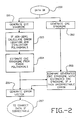
- Fig. 2 is a flow chart of the method of operation of the system according to the present invention for detecting uncorrectable errors in a sector of data.
- the data is read across the bus (block 200).
- the data on the bus is supplied to ECC syndrome generator and the CRC syndrome generator where the ECC syndrome is generated (block 201) and the CRC syndrome is generated (block 202).
- ECC syndrome If the ECC syndrome is non-zero, then error location and value polynomials are calculated (block 203). From the error value polynomial, an estimated CRC syndrome is calculated (block 204). The CRC syndrome generated in block 202 is compared with the CRC syndrome estimated in block 204, and if they are unequal then an uncorrectable error signal is generated (block 205). An error vector is generated in response to the error value and value polynomials and the uncorrectable error signal (block 206). The error vector is then supplied to the system for correction of the data if correctable (block 207).
- the estimated CRC syndrome is generated based on terms of the error value polynomial.
- the error value polynomial is generated using a Chien Search, as known in the art.
- the Chien Search implements a searching algorithm for roots of the error value polynomial from the lowest order to the highest order with respect to the location of data within the sector. This low to high searching is referred to as a forward Chien Search.
- the CRC syndrome is generated from the high to low orders with respect to the data in the sector. Therefore, all terms of the error value polynomial must be generated before calculation of the estimated CRC syndrome may complete.
- the estimated CRC syndrome may be generated as the terms of the error value polynomial are generated if a reverse Chien Search is utilized.
- each term of the error value polynomial as generated is supplied to the CRC detection logic and operated upon.
- the estimated CRC syndrome is supplied. This allows for implementation of the CRC detection logic with less memory, since all terms of the error value polynomial need not be stored for generation of the estimated CRC syndrome.
- the estimated CRC syndrome will be available more quickly because less processing is required after receipt of the last term of the error value polynomial.
- a forward Chien Search it is preferable to use a forward Chien Search because of convenience of implementation for the variable code lengths possible.
- Using a backward Chien Search the last term in the interleave must be found by logic before proceeding with the reverse search. This logic for finding the last term in interleave complicates implementation of the error detection and correction system.
- a forward Chien Search on the other hand, always begins at term zero of the data polynomial.
- a preferred embodiment of the present invention uses a reverse CRC generation polynomial to operate on the error value polynomial terms as they proceed from lowest order to highest order.
- CRC syndrome polynomial s(x) can be calculated from the error value polynomial and the CRC generation polynomial.
- i(x) information polynomial
- g(x) CRC generation polynomial
- c(x) codeword polynomial
- e(x) error value polynomial
- r(x) received codeword polynomial
- n the code length.
- e(x) e n-1 x n-1 + e n-2 x n-2 + ... + e1x + e0
- e R (x) e n-1 + e n-2 x + ... + e1x n-2 + e0x n-1
- g(x) x r + g r-1 x r-1 + ...
- Fig. 3 illustrates an implementation of the CRC detection block for the reverse CRC syndrome S R according to the preferred embodiment of the present invention.
- the CRC detection logic as shown in Fig. 3 is connected to receive the error value polynomial terms as generated across line 23 and in the CRC syndrome terms as generated across line 24.
- the CRC syndrome terms on line 24 are supplied first. They are latched in register ri 50 and supplied across line 51 into 2:1 multiplexer 52.
- the control signal LDSEL is asserted to select the signal on line 51 as the output of multiplexer 52 on line 53.
- the term is latched in register RD3 54 in response to CORDLAT, and supplied on line 55 through buffer 56 to line 57.
- the first term supplied across line 24 is the high order coefficient S3 of the generated CRC syndrome. This term is supplied through adder 58 into register RS3 59 in response to the RSLAT control signal.
- the second term of the CRC syndrome is supplied through register RD3 54 onto line 57 as a first input to multiplexer 60.
- the LDSEL signal asserted to select the second term of the CRC syndrome on its output across line 61 to latch RD2 62.
- the latch RD2 62 accepts the second term in response to the CDRDLAT signal, and supplies it on line 63 through buffer 64 to line 65.
- the second term is supplied through adder 66 to latch RS2 67 in response to the RSLAT control signal.
- the third term of the CRC syndrome supplied across line 24 is latched through RD3 and RD2 onto line 65 and as an input to 2:1 multiplexer 68.
- the LDSEL signal is asserted to select the third term across line 69 as an input to latch RD1 70.
- the third term is latched in RD1 70 and supplied across line 71 through buffer 72 onto line 73.
- the third term is supplied through adder 74 to latch RS1 75 in response to assertion of the RSLAT signal.
- the fourth term of the CRC syndrome 24 is supplied through RI 50, RD3 54, RD2 62, RD1 70 onto line 73 and as an input to 2:1 multiplexer 76.
- the LDSEL signal selects the fourth term as its output on line 77 which is connected to the input of latch RD0 78.
- Latch RD0 stores the fourth term in response to the CDRDLAT signal and supplies it on line 79 through buffer 80 to line 81.
- the fourth term is supplied through adder 82 to latch RS0 83 in response to the RSLAT signal. In this manner, the four terms of the CRC syndrome are latched in reverse order in registers RS0 through RS3, to implement a reverse CRC syndrome.
- the error value polynomial is supplied through 2:1 multiplexer 84 to line 85, if the CRCD.SEL control signal is not asserted.
- the CRCD.SEL control signal is asserted to select all zeros through 2:1 multiplexer 84 if the ECC syndrome is zero and no error value polynomial is generated.
- registers RD0 through RD3 are reset in response to the RDRST signal.
- the first term of the error value polynomial is selected across line 85 through adder 86 and on line 87 as a second input to 2:1 multiplexer 76.
- the LDSEL signal results in selection of the error value term through the multiplexer 76 to line 77 and into RD0 78.
- the second term of the error value polynomial is supplied across line 85 through adder 86 into RD0 while the first term is supplied on line 81 through adder 88, multiplexer 68, line 69 into register RD1 70.
- the third term of the error value polynomial is selected through adder 86, multiplexer 76 and into RD0 78 while the second term is shifted through adder 88, multiplexer 68 into latch RD1 and the first term is shifted along line 71 through buffer 72, line 73, adder 90, line 91, multiplexer 60, line 61 into latch RD2 62.
- the fourth term of the error value polynomial is shifted into RD0 while the third, second and first terms are shifted through the detection logic as before. With the first term being shifted along line 65 through adder 92, line 93, multiplexer 52, line 53 into RD3 54.
- RD3 54 The value in RD3 54 is supplied on line 55 through buffer 56 onto line 57 where it is supplied as input to true and complement generator 94.
- True and complement outputs 96 of the signal generated by true and complement generator 94 are supplied as inputs to multipliers 97, 98, 99, and 100, which require the true and complement inputs to perform multiplication.
- Multiplier 97 multiplies the signal on line 96 by ⁇ 77 and supplies its output on line 101 as a second input to adder 86. Likewise the signal on line 96 is multiplied in multiplier 98 by ⁇ 188 and supplied on line 102 as a second input to adder 88. The signal on line 96 is supplied through multiplier 99 where it is multiplied by ⁇ 57 and supplied on line 103 as a second input to adder 90. Multiplier 100 multiplies a signal on line 96 by ⁇ 215 and supplies its output on line 104 as a second output to adder 92.
- the terms of the error value polynomial are successively latched through the CRC detection circuit of Fig. 3 in response to the CDRDLAT signal until all terms have been received.
- the RSLAT signal is asserted so that the value in RD0 is summed with the value in RS0 and stored in latch RS0.
- the value in RD1 is summed with the value in RS1 and stored in RS1.
- the value in RD2 is summed with the value in RS2 and latched in RS2.
- the value in RD3 is summed with the value in RS3 and latched into RS3.
- the output of RS0 through RS3 on lines 105 through 108 represent a comparison of the estimated CRC syndrome with the generated CRC syndrome.
- the lines 105 through 108 are connected as inputs to NOR gate 109.
- the output of NOR gate 109 is the uncorrectable error signal on line 25. If any of the signals on line 105 through 108 are non-zero, then the uncorrectable error signal will be asserted active low.
- each interleave value is latched into the registers RS0 through RS3 while being scanned with the result of previous interleaves.
- the uncorrectable error signal is sampled.
- the RSRST signal is asserted to clear the latches RS0 through RS3 in order to initialize the circuit for operation on a following sector.
- this CRC detection logic of Fig. 3 implements the reverse CRC generation polynomial, calculates an estimated CRC syndrome.
- the estimated CRC syndrome is compared with the CRC syndrome supplied across line 24 and previously stored in the registers RS0 through RS3. Result of the comparison is supplied on line 25 as the uncorrectable error signal.
- the CRC detection logic illustrated in Fig. 3 allows generation of the estimated CRC syndrome in parallel with the generation of the error value polynomial.
- the uncorrectable error signal can be generated based on a single read of the sector of data, providing a significant performance advantage over prior art error detection and correction systems based on a first code for detecting and correcting errors and a second code for determining whether uncorrectable errors exist in the sector.
- the representative error detection and correction system for which present invention is suited is the X3B11 standard for optical storage media on 51 ⁇ 4 inch disks. Such standard is incorporated by reference in the present application as if fully set forth herein.
Abstract
Description
- Present invention relates to error detection and correction systems employing a first code for detection and correction in errors, and a second code for detecting errors by which the presence of uncorrectable errors is determined.
- A standard encoding specification for 5¼ inch optical storage devices known as X3B11 has been adopted by the data storage systems industry. According to this standard, data is stored in sectors which consist of one or more interleaves of data. A data field error checking and correcting (ECC) code is generated over each interleaf and a data field cyclic redundancy code (CRC) is generated over the XOR sum of data bytes across the interleaves, i.e. to the XOR sum of all data bytes with the same displacement from the beginning of each interleaf.
- The ECC code is utilized to locate and correct correctable errors in each sector. The CRC code is utilized to determine whether errors exist in the sector that may not have been identified and corrected using the ECC code. When such errors are identified, then an uncorrectable sector signal is generated.
- Although this X3B11 specification has been implemented for optical disk systems, it is particularly useful for any data storage system characterized by frequent burst errors.
- Performance of data storage systems using the ECC/CRC codes for identifying uncorrectable errors is limited by the time required to compare the errors located and corrected by the ECC with those detected by the CRC code. A typical system using the X3B11 standard is required first to read the data of a sector, and then to generate a syndrome based on the ECC code. From the syndrome, error location and error value polynomials are generated and the data is corrected. The corrected data is then read for generation of a CRC syndrome. If the generation of the CRC syndrome based on the corrected data is non-zero, then an uncorrectable error is detected. This algorithm is obviously burdensome in that it requires reading of the entire sector of data twice.
- It would be desirable to utilize the two code error checking and correcting systems, such as the X3B11 standard, without requiring two reads of the sector of data involved in the correction, and otherwise improve the performance of error detection and correction systems.
- In a data storage system storing sectors of data in a store, each sector including a data block, an error checking and correcting (ECC) block and a error detecting (CRC) block, an apparatus for signalling the occurrence of uncorrectable errors in a sector, comprising:
a data bus, connected to the store, for communication of the sector;
first means, connected to the data bus and responsive to the ECC block in the sector, for generating an error polynomial identifying a location and value for correctable errors in the sector;
second means, connected to the data bus and responsive to the CRC block in the sector, for generating a syndrome identifying detected errors in the data block;
evaluation means, coupled to the first means and the second means and responsive to the error polynomial and the syndrome, for generating an uncorrectable error signal if the detected errors do not match the correctable errors. - According to one aspect, the error checking and correcting code is a Reed-Solomon code as in the X3B11 standard. Likewise the CRC code is a Reed-Solomon code as in the X3B11 standard. The ECC logic generates the plurality of terms in the error polynomial in an order with respect to the bytes of data in the data block. The syndrome is a second polynomial with a plurality of terms generated in response to a CRC generation polynomial. The evaluation logic implements a reverse CRC generation polynomial having a plurality of terms in the same order as the error polynomial. Detection logic receives the plurality of terms of the error polynomial, generates an estimated CRC syndrome based on the reverse CRC generation polynomial, and generates the uncorrectable error signal if the estimated CRC syndrome is not equal to the generated CRC syndrome.
- Other aspects and advantages of the present invention can be seen by a study of the figures, detailed description and claims below.
-
- Fig. 1 is a block diagram of a data storage system implementing the present invention.
- Fig. 2 is a flow chart illustrating a method according to the present invention.
- Fig. 3 is a diagram of the CRC detection logic utilized in a preferred embodiment of the present invention.
- The present invention is described with reference to Figs. 1, 2 and 3.
- Fig. 1 is a block diagram of a data storage system implementing the present invention. The data storage system includes an optical
disk storage media 10 coupled acrossline 11 to astorage control 12.Storage control 12 is coupled acrossline 13 todata bus 14. Amemory 15 is coupled to the data bus acrossline 16. As data is read from theoptical disk 10 throughstorage control 12 intomemory 15, the data is written into anECC syndrome generator 17 and into aCRC syndrome generator 19 acrossline 18. The ECC syndrome is generated and, if non-zero, supplied acrossline 20 to logic generating error location andvalue polynomials 21. If the ECC syndrome is zero, a control signal indicating the same is supplied online 20. The terms of the error value polynomial, or the control signal indicating no errors detected, are supplied acrossline 23 to CRC detection logic and a CRC syndrome generated by the CRCsyndrome generator 19 is supplied acrossline 24 to theCRC detection logic 22. As the terms of the error value polynomial become available,CRC detection logic 22 generates an estimated CRC syndrome and compares it with the syndrome generated in theCRC generator 19. If the control signal is asserted, indicating no detected errors in the ECC logic, the estimated CRC syndrome is zero. - If the estimated CRC syndrome and the generated CRC syndrome are equal, then all errors are corrected, otherwise an uncorrectable error signal is generated on
line 25 by theCRC detection logic 22. - The error location and value polynomials are supplied on
line 26 to anerror vector generator 27. Theerror vector generator 27 is also coupled to receive the uncorrectable error signal online 25. An error vector is then supplied online 28 to thedata bus 14. The error vector can then be utilized in the system to correct the data stored in thememory 15, if no uncorrectable errors were detected. - Fig. 2 is a flow chart of the method of operation of the system according to the present invention for detecting uncorrectable errors in a sector of data.
- First, the data is read across the bus (block 200). The data on the bus is supplied to ECC syndrome generator and the CRC syndrome generator where the ECC syndrome is generated (block 201) and the CRC syndrome is generated (block 202).
- If the ECC syndrome is non-zero, then error location and value polynomials are calculated (block 203). From the error value polynomial, an estimated CRC syndrome is calculated (block 204). The CRC syndrome generated in
block 202 is compared with the CRC syndrome estimated inblock 204, and if they are unequal then an uncorrectable error signal is generated (block 205). An error vector is generated in response to the error value and value polynomials and the uncorrectable error signal (block 206). The error vector is then supplied to the system for correction of the data if correctable (block 207). - The estimated CRC syndrome is generated based on terms of the error value polynomial. The error value polynomial is generated using a Chien Search, as known in the art. The Chien Search implements a searching algorithm for roots of the error value polynomial from the lowest order to the highest order with respect to the location of data within the sector. This low to high searching is referred to as a forward Chien Search.
- The CRC syndrome is generated from the high to low orders with respect to the data in the sector. Therefore, all terms of the error value polynomial must be generated before calculation of the estimated CRC syndrome may complete.
- The estimated CRC syndrome may be generated as the terms of the error value polynomial are generated if a reverse Chien Search is utilized. In this embodiment, each term of the error value polynomial as generated is supplied to the CRC detection logic and operated upon. When the last term of the error value polynomial is supplied to the CRC detection logic, the estimated CRC syndrome is supplied. This allows for implementation of the CRC detection logic with less memory, since all terms of the error value polynomial need not be stored for generation of the estimated CRC syndrome. In addition, the estimated CRC syndrome will be available more quickly because less processing is required after receipt of the last term of the error value polynomial.
- It is preferable to use a forward Chien Search because of convenience of implementation for the variable code lengths possible. Using a backward Chien Search, the last term in the interleave must be found by logic before proceeding with the reverse search. This logic for finding the last term in interleave complicates implementation of the error detection and correction system. A forward Chien Search, on the other hand, always begins at term zero of the data polynomial.
- However, since the order of the error locations coming out of a forward Chien Search block is reversed, a preferred embodiment of the present invention uses a reverse CRC generation polynomial to operate on the error value polynomial terms as they proceed from lowest order to highest order.
- If e(x) is an error value polynomial,
e(x) = e₀ + e₁x = e₂x² + ... + en-2xn-2 + en-1xn-1
where ei can be 0 for i = 0, 1, ..., n-1. - Then with a forward Chien Search, the order of the coefficients generated goes from e₀ to en-1. And with a backward Chien Search en-1 comes first and e₀ comes last.
- The following proof demonstrates that the CRC syndrome polynomial s(x) can be calculated from the error value polynomial and the CRC generation polynomial.
Let i(x) = information polynomial,
g(x) = CRC generation polynomial,
c(x) = codeword polynomial,
e(x) = error value polynomial,
r(x) = received codeword polynomial,
and s(x) = CRC syndrome polynomial,
with deg [g(x)] = r.
Then c(x) = i(x) · xr + [i(x) · xr] mod g(x),
r(x) = c(x) + e(x),
and s(x) = r(x) mod g(x).
Then s(x) = r(x) mod g(x)
= [c(x) + e(x)] mod g(x)
= c(X) mod g(x) + e(x) mod g(x).
= e(x) mod g(x) - So if error estimation is correct, then s(x) = r(x) mod g(x) from CRC syndrome generation block should be the same as e(x) mod g(x) using estimated errors from error value and location generation unit.
- If not, uncorrectable errors occurred.
- The following proof demonstrates that the reciprocal of the CRC syndrome can be generated from the results of a forward Chien Search and a reverse CRC generation polynomial.
- e₀, e₁, e₂, ..., en-2, en-1 in availability order
- en-1, en-2, ..., e₂, e₁, e₀ in order of availability
Let n be the code length.
With e(x) = en-1xn-1 + en-2xn-2 + ... + e₁x + e₀
where ei can be 0, i = 0, 1, ..., n-1,
Let eR(x) = en-1 + en-2x + ... + e₁xn-2 + e₀xn-1.
With g(x) = xr + gr-1xr-1 + ... + g₁x = g₀,
gR(x) = 1 + gr-1x + ... + g₁xr-1 + g₀xr.
With s(x) = sr-1xr-1 + sr-2xr-2 + ...+ s₁x + s₀,
sR(x) = s₀xr-1 + s₁xr-2 + ...+ sr-2x + sr-1.
Then from s(x) = e(x) mod g(x)
e(x) = q(x) g(x) + s(x)
→ eR(x) = xn-1 e(x⁻¹)
= xn-1(q(x⁻¹) · g(x⁻¹) + s(x⁻¹))
= qR(x) · gR(x) + xn-1s(x⁻¹)
= qR(x) · gR(x) + xn-rsR(x)
⇒ g₀xreR(x) = goxrqR(x) · gR(x) + g₀xnsR(x)
⇒ g₀xreR(x) mod gR(x) = -sR(x) = sR(x) - For a standard X3B11 implementation, the reverse CRC generation polynomial is calculated as follows.

= α⁴⁰x⁴eR(x)mod(α⁴⁰(x⁴ + α⁷⁷x³ + α¹⁸⁸x² + α⁵⁷x + α²¹⁵),
= x⁴eR(x)mod[x⁴ + α⁷⁷x³ + α¹⁸⁸x² + α⁵⁷x + α²¹⁵]. - Fig. 3 illustrates an implementation of the CRC detection block for the reverse CRC syndrome SRaccording to the preferred embodiment of the present invention.

- The CRC detection logic as shown in Fig. 3 is connected to receive the error value polynomial terms as generated across
line 23 and in the CRC syndrome terms as generated acrossline 24. The CRC syndrome terms online 24 are supplied first. They are latched in register ri 50 and supplied acrossline 51 into 2:1multiplexer 52. During loading of the CRC syndrome terms, the control signal LDSEL is asserted to select the signal online 51 as the output ofmultiplexer 52 online 53. The term is latched inregister RD3 54 in response to CORDLAT, and supplied online 55 throughbuffer 56 toline 57. - The first term supplied across
line 24 is the high order coefficient S3 of the generated CRC syndrome. This term is supplied throughadder 58 intoregister RS3 59 in response to the RSLAT control signal. - The second term of the CRC syndrome is supplied through
register RD3 54 ontoline 57 as a first input tomultiplexer 60. The LDSEL signal asserted to select the second term of the CRC syndrome on its output acrossline 61 to latchRD2 62. Thelatch RD2 62 accepts the second term in response to the CDRDLAT signal, and supplies it online 63 throughbuffer 64 toline 65. The second term is supplied throughadder 66 to latchRS2 67 in response to the RSLAT control signal. - The third term of the CRC syndrome supplied across
line 24 is latched through RD3 and RD2 ontoline 65 and as an input to 2:1multiplexer 68. The LDSEL signal is asserted to select the third term acrossline 69 as an input to latchRD1 70. In response to a third assertion of CDRDLAT, the third term is latched inRD1 70 and supplied across line 71 throughbuffer 72 ontoline 73. The third term is supplied throughadder 74 to latchRS1 75 in response to assertion of the RSLAT signal. The fourth term of theCRC syndrome 24 is supplied through RI 50,RD3 54,RD2 62,RD1 70 ontoline 73 and as an input to 2:1multiplexer 76. The LDSEL signal selects the fourth term as its output online 77 which is connected to the input oflatch RD0 78. Latch RD0 stores the fourth term in response to the CDRDLAT signal and supplies it online 79 throughbuffer 80 toline 81. The fourth term is supplied throughadder 82 to latchRS0 83 in response to the RSLAT signal. In this manner, the four terms of the CRC syndrome are latched in reverse order in registers RS0 through RS3, to implement a reverse CRC syndrome. - After loading of the CRC syndrome, the error value polynomial is supplied through 2:1
multiplexer 84 toline 85, if the CRCD.SEL control signal is not asserted. The CRCD.SEL control signal is asserted to select all zeros through 2:1multiplexer 84 if the ECC syndrome is zero and no error value polynomial is generated. - First, registers RD0 through RD3 are reset in response to the RDRST signal. The first term of the error value polynomial is selected across
line 85 throughadder 86 and online 87 as a second input to 2:1multiplexer 76. The LDSEL signal results in selection of the error value term through themultiplexer 76 toline 77 and intoRD0 78. The second term of the error value polynomial is supplied acrossline 85 throughadder 86 into RD0 while the first term is supplied online 81 throughadder 88,multiplexer 68,line 69 intoregister RD1 70. The third term of the error value polynomial is selected throughadder 86,multiplexer 76 and intoRD0 78 while the second term is shifted throughadder 88,multiplexer 68 into latch RD1 and the first term is shifted along line 71 throughbuffer 72,line 73,adder 90,line 91,multiplexer 60,line 61 intolatch RD2 62. Finally, the fourth term of the error value polynomial is shifted into RD0 while the third, second and first terms are shifted through the detection logic as before. With the first term being shifted alongline 65 throughadder 92,line 93,multiplexer 52,line 53 intoRD3 54. The value inRD3 54 is supplied online 55 throughbuffer 56 ontoline 57 where it is supplied as input to true andcomplement generator 94. True and complementoutputs 96 of the signal generated by true andcomplement generator 94 are supplied as inputs tomultipliers -
Multiplier 97 multiplies the signal online 96 by α⁷⁷ and supplies its output online 101 as a second input to adder 86. Likewise the signal online 96 is multiplied inmultiplier 98 by α¹⁸⁸ and supplied online 102 as a second input to adder 88. The signal online 96 is supplied throughmultiplier 99 where it is multiplied by α⁵⁷ and supplied online 103 as a second input to adder 90.Multiplier 100 multiplies a signal online 96 by α²¹⁵ and supplies its output online 104 as a second output to adder 92. - As the terms of the error value polynomial are generated, they are successively latched through the CRC detection circuit of Fig. 3 in response to the CDRDLAT signal until all terms have been received. When all terms have been received, the RSLAT signal is asserted so that the value in RD0 is summed with the value in RS0 and stored in latch RS0. The value in RD1 is summed with the value in RS1 and stored in RS1. The value in RD2 is summed with the value in RS2 and latched in RS2. Finally, the value in RD3 is summed with the value in RS3 and latched into RS3.
- For a single interleave sector, the output of RS0 through RS3 on lines 105 through 108 represent a comparison of the estimated CRC syndrome with the generated CRC syndrome.
- The lines 105 through 108 are connected as inputs to NOR
gate 109. The output of NORgate 109 is the uncorrectable error signal online 25. If any of the signals on line 105 through 108 are non-zero, then the uncorrectable error signal will be asserted active low. - For a sector involving a plurality of interleaves, each interleave value is latched into the registers RS0 through RS3 while being scanned with the result of previous interleaves. On receipt of the final term of the final interleave, the uncorrectable error signal is sampled.
- After performance of the CRC detection using the circuit of Fig. 3, the RSRST signal is asserted to clear the latches RS0 through RS3 in order to initialize the circuit for operation on a following sector.
- As can be seen, this CRC detection logic of Fig. 3 implements the reverse CRC generation polynomial, calculates an estimated CRC syndrome. The estimated CRC syndrome is compared with the CRC syndrome supplied across
line 24 and previously stored in the registers RS0 through RS3. Result of the comparison is supplied online 25 as the uncorrectable error signal. - Equivalent circuits could be implemented in which the CRC syndrome on
line 24 is stored in latches separate from RS0 through RS3. The outputs of such latches could be compared using XOR gates or other comparators as known in the art without requiring loading of the RS0 through RS3 latches with the generated CRC syndrome fromline 24. - The CRC detection logic illustrated in Fig. 3 allows generation of the estimated CRC syndrome in parallel with the generation of the error value polynomial. In addition, the uncorrectable error signal can be generated based on a single read of the sector of data, providing a significant performance advantage over prior art error detection and correction systems based on a first code for detecting and correcting errors and a second code for determining whether uncorrectable errors exist in the sector.
- The representative error detection and correction system for which present invention is suited is the X3B11 standard for optical storage media on 5¼ inch disks. Such standard is incorporated by reference in the present application as if fully set forth herein.
- The foregoing description of preferred embodiments of the present invention has been provided for the purposes of illustration and description. It is not intended to be exhaustive or to limit the invention to the precise forms disclosed. Obviously, many modifications and variations will be apparent to practitioners skilled in this art. The embodiments were chosen and described in order to best explain the principles of the invention and its practical application, thereby enabling others skilled in the art to understand the invention for various embodiments and with various modifications as are suited to the particular use contemplated. It is intended that the scope of the invention be defined by the following claims and their equivalents.
Claims (26)
a data bus, connected to the store, for communication of the sector;
first means, connected to the data bus and responsive to the ECC block in the sector, for generating an error polynomial identifying a location and value for correctable errors in the sector;
second means, connected to the data bus and responsive to the CRC block in the sector, for generating a syndrome identifying detected errors in the data block;
evaluation means, coupled to the first means and the second means and responsive to the error polynomial and the syndrome, for generating an uncorrectable error signal if the detected errors do not match the correctable errors.
means for reversing the second polynomial to generate a reverse second polynomial having a plurality of terms from low order to high order;
detection means, coupled with the means for reversing and receiving the plurality of terms of the error polynomial as generated and responsive to the reverse second polynomial, for generating the uncorrectable error signal.
means for combining the error polynomial with a reverse CRC generation polynomial to generate an estimated reverse second polynomial; and
means, connected to the means for combining and the means for reversing, for comparing the reverse second polynomial with the estimated reverse second polynomial to indicate the occurrence of uncorrectable errors.
communicating the sector across a data bus;
generating in error detecting and correcting logic in response to the sector on the data bus, an error polynomial including a plurality of terms, identifying a location and value for correctable errors in the sector;
generating in error detecting logic in response to the sector on the data bus, a syndrome identifying detected errors in the data block and storing the syndrome;
generating in combining logic in response to the error polynomial and the syndrome, an uncorrectable error signal if the detected errors do not match the correctable errors.
reversing the second polynomial to implement a reverse second polynomial having a plurality of terms from low order to high order;
generating the uncorrectable error signal in response to the plurality of terms of the error polynomial and to the reverse second polynomial.
combining the error polynomial with a reverse CRC generation polynomial to generate an estimated reverse second polynomial; and
comparing the reverse second polynomial with the estimated reverse second polynomial to indicate the occurrence of uncorrectable errors.
a data bus, connected to the store, for communication of the sector;
first means, connected to the data bus and responsive to the ECC block in the sector, for generating an error polynomial identifying a location and value for correctable errors in the sector, wherein the error polynomial has a plurality of terms generated from low order to high order with respect to bytes of data in the data block;
second means, connected to the data bus and responsive to the CRC block in the sector, for generating a syndrome identifying detected errors in the data block, wherein the syndrome is a second polynomial with a plurality of terms generated from high order to low order based on a CRC generation polynomial with a plurality of terms;
means for reversing the second polynomial to implement a reverse second polynomial having a plurality of terms from low order to high order;
detection means, coupled with the means for reversing and receiving the plurality of terms of the error polynomial as generated and responsive to the reverse second polynomial, for generating an uncorrectable error signal if the detected errors do not match the correctable errors.
means for combining the error polynomial with a reverse CRC generation polynomial to generate an estimated reverse second polynomial; and
means, connected to the means for combining and the means for reversing, for comparing the reverse second polynomial with the estimated reverse second polynomial to indicate the occurrence of uncorrectable errors.
Applications Claiming Priority (2)
| Application Number | Priority Date | Filing Date | Title |
|---|---|---|---|
| US07/258,240 US5027357A (en) | 1988-10-14 | 1988-10-14 | ECC/CRC error detection and correction system |
| US258240 | 1999-02-26 |
Publications (2)
| Publication Number | Publication Date |
|---|---|
| EP0364172A2 true EP0364172A2 (en) | 1990-04-18 |
| EP0364172A3 EP0364172A3 (en) | 1991-12-04 |
Family
ID=22979693
Family Applications (1)
| Application Number | Title | Priority Date | Filing Date |
|---|---|---|---|
| EP19890310257 Withdrawn EP0364172A3 (en) | 1988-10-14 | 1989-10-06 | Error detection and correction for a data storage system |
Country Status (3)
| Country | Link |
|---|---|
| US (1) | US5027357A (en) |
| EP (1) | EP0364172A3 (en) |
| JP (1) | JPH02211723A (en) |
Cited By (7)
| Publication number | Priority date | Publication date | Assignee | Title |
|---|---|---|---|---|
| WO1991013437A1 (en) * | 1990-02-20 | 1991-09-05 | Eastman Kodak Company | A high speed encoder for non-systematic codes |
| EP0596340A2 (en) * | 1992-11-04 | 1994-05-11 | Mitsubishi Denki Kabushiki Kaisha | Error correction circuit |
| WO1996008873A1 (en) * | 1994-09-16 | 1996-03-21 | Cirrus Logic, Inc. | Versatile error correction system |
| EP0729674A1 (en) * | 1993-11-04 | 1996-09-04 | Cirrus Logic, Inc. | Cyclical redundancy check method and apparatus |
| ES2103225A1 (en) * | 1993-05-25 | 1997-09-01 | Contadores De Agua De Zaragoza | Improvements in fluid meters |
| KR100327653B1 (en) * | 1999-03-16 | 2002-03-08 | 포만 제프리 엘 | Method and apparatus for updating cyclic redundancy check information for data storage |
| EP2248264A1 (en) * | 2008-03-01 | 2010-11-10 | Kabushiki Kaisha Toshiba | Chien search device and chien search method |
Families Citing this family (50)
| Publication number | Priority date | Publication date | Assignee | Title |
|---|---|---|---|---|
| US5157669A (en) * | 1988-10-14 | 1992-10-20 | Advanced Micro Devices, Inc. | Comparison of an estimated CRC syndrome to a generated CRC syndrome in an ECC/CRC system to detect uncorrectable errors |
| JP2591242B2 (en) * | 1990-04-02 | 1997-03-19 | 松下電器産業株式会社 | Error detection method |
| EP0470451A3 (en) * | 1990-08-07 | 1993-01-20 | National Semiconductor Corporation | Implementation of the high-level data link control cyclic redundancy check (hdlc crc) calculation |
| JP2721099B2 (en) * | 1991-12-18 | 1998-03-04 | インターナショナル・ビジネス・マシーンズ・コーポレイション | Trial and error method for error burst correction and multibyte error correction method |
| US5379415A (en) * | 1992-09-29 | 1995-01-03 | Zitel Corporation | Fault tolerant memory system |
| US5384788A (en) * | 1992-10-26 | 1995-01-24 | Dell Usa, L.P. | Apparatus and method for optimal error correcting code to parity conversion |
| US5432801A (en) * | 1993-07-23 | 1995-07-11 | Commodore Electronics Limited | Method and apparatus for performing multiple simultaneous error detection on data having unknown format |
| US5774481A (en) * | 1995-03-31 | 1998-06-30 | International Business Machines Corporation | Reduced gate error detection and correction circuit |
| US5719885A (en) * | 1995-12-28 | 1998-02-17 | Emc Corporation | Storage reliability method and apparatus |
| US5774647A (en) * | 1996-05-15 | 1998-06-30 | Hewlett-Packard Company | Management of memory modules |
| US5822339A (en) * | 1996-05-30 | 1998-10-13 | Rockwell International | Data decoder and method to correct inversions or phase ambiguity for M-ary transmitted data |
| US6052815A (en) * | 1997-11-14 | 2000-04-18 | Cirrus Logic, Inc. | ECC system for generating a CRC syndrome over randomized data in a computer storage device |
| US5996105A (en) * | 1997-11-14 | 1999-11-30 | Cirrus Logic, Inc. | ECC system employing a data buffer for storing codeword data and a syndrome buffer for storing error syndromes |
| US5991911A (en) * | 1997-11-14 | 1999-11-23 | Cirrus Logic, Inc. | Concurrent generation of ECC error syndromes and CRC validation syndromes in a DVD storage device |
| US6092231A (en) * | 1998-06-12 | 2000-07-18 | Qlogic Corporation | Circuit and method for rapid checking of error correction codes using cyclic redundancy check |
| US6158040A (en) * | 1998-07-29 | 2000-12-05 | Neomagic Corp. | Rotated data-aligmnent in wade embedded DRAM for page-mode column ECC in a DVD controller |
| US6115837A (en) * | 1998-07-29 | 2000-09-05 | Neomagic Corp. | Dual-column syndrome generation for DVD error correction using an embedded DRAM |
| US6438724B1 (en) | 1999-03-16 | 2002-08-20 | International Business Machines Corporation | Method and apparatus for deterministically altering cyclic redundancy check information for data storage |
| US6751771B2 (en) | 2000-02-11 | 2004-06-15 | Mediatek, Inc. | Method and apparatus for error processing in optical disk memories |
| TW569188B (en) * | 2001-02-07 | 2004-01-01 | Media Tek Inc | Method and apparatus for error processing in optical disk memories |
| US20030140302A1 (en) * | 2002-01-23 | 2003-07-24 | Litwin, Louis Robert | Chien search cell for an error-correcting decoder |
| US7111228B1 (en) | 2002-05-07 | 2006-09-19 | Marvell International Ltd. | System and method for performing parity checks in disk storage system |
| JP2003346432A (en) * | 2002-05-22 | 2003-12-05 | Internatl Business Mach Corp <Ibm> | Data storage device and data processing method |
| US20040088497A1 (en) * | 2002-11-06 | 2004-05-06 | Deans Russell C. | Methods and apparatus for exchanging data using cyclic redundancy check codes |
| US7287102B1 (en) | 2003-01-31 | 2007-10-23 | Marvell International Ltd. | System and method for concatenating data |
| US7007114B1 (en) | 2003-01-31 | 2006-02-28 | Qlogic Corporation | System and method for padding data blocks and/or removing padding from data blocks in storage controllers |
| US7219182B2 (en) * | 2003-03-10 | 2007-05-15 | Marvell International Ltd. | Method and system for using an external bus controller in embedded disk controllers |
| US7064915B1 (en) | 2003-03-10 | 2006-06-20 | Marvell International Ltd. | Method and system for collecting servo field data from programmable devices in embedded disk controllers |
| US7039771B1 (en) | 2003-03-10 | 2006-05-02 | Marvell International Ltd. | Method and system for supporting multiple external serial port devices using a serial port controller in embedded disk controllers |
| US7870346B2 (en) * | 2003-03-10 | 2011-01-11 | Marvell International Ltd. | Servo controller interface module for embedded disk controllers |
| US7492545B1 (en) | 2003-03-10 | 2009-02-17 | Marvell International Ltd. | Method and system for automatic time base adjustment for disk drive servo controllers |
| US7228485B1 (en) | 2003-04-03 | 2007-06-05 | Marvell International Ltd. | Error correction using error detection codes |
| US7526691B1 (en) | 2003-10-15 | 2009-04-28 | Marvell International Ltd. | System and method for using TAP controllers |
| KR100594241B1 (en) * | 2004-01-29 | 2006-06-30 | 삼성전자주식회사 | RS decoder circuit having forward Chien search type |
| US7139150B2 (en) * | 2004-02-10 | 2006-11-21 | Marvell International Ltd. | Method and system for head position control in embedded disk drive controllers |
| US7120084B2 (en) | 2004-06-14 | 2006-10-10 | Marvell International Ltd. | Integrated memory controller |
| US8166217B2 (en) * | 2004-06-28 | 2012-04-24 | Marvell International Ltd. | System and method for reading and writing data using storage controllers |
| US9201599B2 (en) * | 2004-07-19 | 2015-12-01 | Marvell International Ltd. | System and method for transmitting data in storage controllers |
| US8032674B2 (en) * | 2004-07-19 | 2011-10-04 | Marvell International Ltd. | System and method for controlling buffer memory overflow and underflow conditions in storage controllers |
| US7757009B2 (en) * | 2004-07-19 | 2010-07-13 | Marvell International Ltd. | Storage controllers with dynamic WWN storage modules and methods for managing data and connections between a host and a storage device |
| JP4321394B2 (en) * | 2004-07-21 | 2009-08-26 | 富士通株式会社 | Encoding device, decoding device |
| US7386661B2 (en) | 2004-10-13 | 2008-06-10 | Marvell International Ltd. | Power save module for storage controllers |
| US7240267B2 (en) | 2004-11-08 | 2007-07-03 | Marvell International Ltd. | System and method for conducting BIST operations |
| US7802026B2 (en) * | 2004-11-15 | 2010-09-21 | Marvell International Ltd. | Method and system for processing frames in storage controllers |
| US7609468B2 (en) * | 2005-04-06 | 2009-10-27 | Marvell International Ltd. | Method and system for read gate timing control for storage controllers |
| US7937643B1 (en) | 2006-09-18 | 2011-05-03 | Mediatek Inc. | Mobile communication device and data reception method |
| US8762818B1 (en) * | 2009-03-05 | 2014-06-24 | Marvell International Ltd. | System and methods for performing decoding error detection in a storage device |
| CN101908376B (en) * | 2009-06-04 | 2014-05-21 | 威刚科技(苏州)有限公司 | Non-volatile storage device and control method thereof |
| US8578240B1 (en) * | 2011-01-21 | 2013-11-05 | Juniper Networks, Inc. | CRC computation for packet length not multiple of data path width |
| US9298529B2 (en) | 2014-05-29 | 2016-03-29 | Freescale Semiconductor, Inc. | Indicating internal transmitter errors in a controller area network (CAN) |
Citations (3)
| Publication number | Priority date | Publication date | Assignee | Title |
|---|---|---|---|---|
| EP0156440A2 (en) * | 1984-03-24 | 1985-10-02 | Koninklijke Philips Electronics N.V. | An information transmission method with error correction for user words, an error correcting decoding method for such user words, an apparatus for information transmission for use with the method, a device for information decoding for use with the method and an apparatus for use with such device |
| JPS61258373A (en) * | 1985-05-13 | 1986-11-15 | Matsushita Electric Ind Co Ltd | Error detector |
| EP0278700A2 (en) * | 1987-02-10 | 1988-08-17 | Sony Corporation | Error correction methods and apparatus |
Family Cites Families (1)
| Publication number | Priority date | Publication date | Assignee | Title |
|---|---|---|---|---|
| CA1258134A (en) * | 1985-04-13 | 1989-08-01 | Yoichiro Sako | Error correction method |
-
1988
- 1988-10-14 US US07/258,240 patent/US5027357A/en not_active Expired - Lifetime
-
1989
- 1989-10-06 EP EP19890310257 patent/EP0364172A3/en not_active Withdrawn
- 1989-10-14 JP JP1267968A patent/JPH02211723A/en active Pending
Patent Citations (3)
| Publication number | Priority date | Publication date | Assignee | Title |
|---|---|---|---|---|
| EP0156440A2 (en) * | 1984-03-24 | 1985-10-02 | Koninklijke Philips Electronics N.V. | An information transmission method with error correction for user words, an error correcting decoding method for such user words, an apparatus for information transmission for use with the method, a device for information decoding for use with the method and an apparatus for use with such device |
| JPS61258373A (en) * | 1985-05-13 | 1986-11-15 | Matsushita Electric Ind Co Ltd | Error detector |
| EP0278700A2 (en) * | 1987-02-10 | 1988-08-17 | Sony Corporation | Error correction methods and apparatus |
Non-Patent Citations (1)
| Title |
|---|
| PATENT ABSTRACTS OF JAPAN vol. 11, no. 109 (P-564)(2556) 7 April 1987 & JP-A-61 258 373 ( MATSUSHITA ELECTRIC IND. CO. LDT. ) 15 October 1985 * |
Cited By (17)
| Publication number | Priority date | Publication date | Assignee | Title |
|---|---|---|---|---|
| WO1991013437A1 (en) * | 1990-02-20 | 1991-09-05 | Eastman Kodak Company | A high speed encoder for non-systematic codes |
| EP0596340A2 (en) * | 1992-11-04 | 1994-05-11 | Mitsubishi Denki Kabushiki Kaisha | Error correction circuit |
| EP0596340A3 (en) * | 1992-11-04 | 1995-09-27 | Mitsubishi Electric Corp | Error correction circuit. |
| EP0880237A1 (en) * | 1992-11-04 | 1998-11-25 | Mitsubishi Denki Kabushiki Kaisha | Error correction circuit |
| ES2103225A1 (en) * | 1993-05-25 | 1997-09-01 | Contadores De Agua De Zaragoza | Improvements in fluid meters |
| EP0729674A1 (en) * | 1993-11-04 | 1996-09-04 | Cirrus Logic, Inc. | Cyclical redundancy check method and apparatus |
| US5592404A (en) * | 1993-11-04 | 1997-01-07 | Cirrus Logic, Inc. | Versatile error correction system |
| EP0729674A4 (en) * | 1993-11-04 | 1997-10-15 | Cirrus Logic Inc | Cyclical redundancy check method and apparatus |
| WO1996008873A1 (en) * | 1994-09-16 | 1996-03-21 | Cirrus Logic, Inc. | Versatile error correction system |
| EP0973267A2 (en) * | 1994-09-16 | 2000-01-19 | Cirrus Logic, Inc. | Error correction method |
| EP0974968A2 (en) * | 1994-09-16 | 2000-01-26 | Cirrus Logic, Inc. | An error correction system for a compact disk drive |
| EP0973267A3 (en) * | 1994-09-16 | 2003-10-15 | Cirrus Logic, Inc. | Error correction method |
| EP0974968A3 (en) * | 1994-09-16 | 2003-12-03 | Cirrus Logic, Inc. | An error correction system for a compact disk drive |
| KR100327653B1 (en) * | 1999-03-16 | 2002-03-08 | 포만 제프리 엘 | Method and apparatus for updating cyclic redundancy check information for data storage |
| EP2248264A1 (en) * | 2008-03-01 | 2010-11-10 | Kabushiki Kaisha Toshiba | Chien search device and chien search method |
| EP2248264A4 (en) * | 2008-03-01 | 2011-07-06 | Toshiba Kk | Chien search device and chien search method |
| US8418028B2 (en) | 2008-03-01 | 2013-04-09 | Kabushiki Kaisha Toshiba | Chien search device and Chien search method |
Also Published As
| Publication number | Publication date |
|---|---|
| EP0364172A3 (en) | 1991-12-04 |
| JPH02211723A (en) | 1990-08-23 |
| US5027357A (en) | 1991-06-25 |
Similar Documents
| Publication | Publication Date | Title |
|---|---|---|
| EP0364172A2 (en) | Error detection and correction for a data storage system | |
| US5157669A (en) | Comparison of an estimated CRC syndrome to a generated CRC syndrome in an ECC/CRC system to detect uncorrectable errors | |
| US5659557A (en) | Reed-Solomon code system employing k-bit serial techniques for encoding and burst error trapping | |
| US4142174A (en) | High speed decoding of Reed-Solomon codes | |
| US4099160A (en) | Error location apparatus and methods | |
| US4763332A (en) | Shared circuitry for the encoding and syndrome generation functions of a Reed-Solomon code | |
| US6560747B1 (en) | Error counting mechanism | |
| US6192497B1 (en) | Parallel Chien search circuit | |
| EP0155038B1 (en) | Fast decoder for reed-solomon codes which can also be used as an encoder, and recording/playback apparatus comprising such an encoder/decoder | |
| US6574774B1 (en) | Physical block address recovery apparatus system and method for cyclic error correction codes | |
| US6374383B1 (en) | Determining error locations using error correction codes | |
| EP0167627B1 (en) | Method and apparatus for decoding error correction code | |
| US6272659B1 (en) | Error correction code processor employing adjustable correction power for miscorrection minimization | |
| US5602857A (en) | Error correction method and apparatus | |
| US5715262A (en) | Errors and erasures correcting reed-solomon decoder | |
| US5942005A (en) | Method and means for computationally efficient error and erasure correction in linear cyclic codes | |
| EP0357461A2 (en) | Error correction circuit | |
| JP2000165259A (en) | Data decoding processor and its method | |
| WO1997000559A1 (en) | Dedicated alu architecture for 10-bit reed-solomon error correction module | |
| US8201061B2 (en) | Decoding error correction codes using a modular single recursion implementation | |
| JP4733403B2 (en) | Decoder, data storage device, and data error correction method | |
| US5329535A (en) | Variable block lengths on-the-fly error correcting decoder | |
| US6868517B1 (en) | Method and apparatus for checking read errors with two cyclic redundancy check stages | |
| EP1486872A1 (en) | Correcting erroneous data using redundancy blocks | |
| US6651214B1 (en) | Bi-directional decodable Reed-Solomon codes |
Legal Events
| Date | Code | Title | Description |
|---|---|---|---|
| PUAI | Public reference made under article 153(3) epc to a published international application that has entered the european phase |
Free format text: ORIGINAL CODE: 0009012 |
|
| AK | Designated contracting states |
Kind code of ref document: A2 Designated state(s): AT BE CH DE ES FR GB GR IT LI LU NL SE |
|
| PUAL | Search report despatched |
Free format text: ORIGINAL CODE: 0009013 |
|
| AK | Designated contracting states |
Kind code of ref document: A3 Designated state(s): AT BE CH DE ES FR GB GR IT LI LU NL SE |
|
| 17P | Request for examination filed |
Effective date: 19920306 |
|
| 17Q | First examination report despatched |
Effective date: 19930316 |
|
| STAA | Information on the status of an ep patent application or granted ep patent |
Free format text: STATUS: THE APPLICATION IS DEEMED TO BE WITHDRAWN |
|
| 18D | Application deemed to be withdrawn |
Effective date: 19940525 |