EP0364420B1 - A device for transluminal implantation or extraction - Google Patents
A device for transluminal implantation or extraction Download PDFInfo
- Publication number
- EP0364420B1 EP0364420B1 EP89850313A EP89850313A EP0364420B1 EP 0364420 B1 EP0364420 B1 EP 0364420B1 EP 89850313 A EP89850313 A EP 89850313A EP 89850313 A EP89850313 A EP 89850313A EP 0364420 B1 EP0364420 B1 EP 0364420B1
- Authority
- EP
- European Patent Office
- Prior art keywords
- tube
- central tube
- stent
- distal end
- members
- Prior art date
- Legal status (The legal status is an assumption and is not a legal conclusion. Google has not performed a legal analysis and makes no representation as to the accuracy of the status listed.)
- Expired - Lifetime
Links
Images

Classifications
-
- A—HUMAN NECESSITIES
- A61—MEDICAL OR VETERINARY SCIENCE; HYGIENE
- A61B—DIAGNOSIS; SURGERY; IDENTIFICATION
- A61B17/00—Surgical instruments, devices or methods, e.g. tourniquets
- A61B17/28—Surgical forceps
- A61B17/29—Forceps for use in minimally invasive surgery
-
- A—HUMAN NECESSITIES
- A61—MEDICAL OR VETERINARY SCIENCE; HYGIENE
- A61F—FILTERS IMPLANTABLE INTO BLOOD VESSELS; PROSTHESES; DEVICES PROVIDING PATENCY TO, OR PREVENTING COLLAPSING OF, TUBULAR STRUCTURES OF THE BODY, e.g. STENTS; ORTHOPAEDIC, NURSING OR CONTRACEPTIVE DEVICES; FOMENTATION; TREATMENT OR PROTECTION OF EYES OR EARS; BANDAGES, DRESSINGS OR ABSORBENT PADS; FIRST-AID KITS
- A61F2/00—Filters implantable into blood vessels; Prostheses, i.e. artificial substitutes or replacements for parts of the body; Appliances for connecting them with the body; Devices providing patency to, or preventing collapsing of, tubular structures of the body, e.g. stents
- A61F2/95—Instruments specially adapted for placement or removal of stents or stent-grafts
-
- A—HUMAN NECESSITIES
- A61—MEDICAL OR VETERINARY SCIENCE; HYGIENE
- A61B—DIAGNOSIS; SURGERY; IDENTIFICATION
- A61B17/00—Surgical instruments, devices or methods, e.g. tourniquets
- A61B17/30—Surgical pincettes without pivotal connections
- A61B2017/303—Surgical pincettes without pivotal connections with four or more legs
-
- A—HUMAN NECESSITIES
- A61—MEDICAL OR VETERINARY SCIENCE; HYGIENE
- A61B—DIAGNOSIS; SURGERY; IDENTIFICATION
- A61B18/00—Surgical instruments, devices or methods for transferring non-mechanical forms of energy to or from the body
- A61B2018/00982—Surgical instruments, devices or methods for transferring non-mechanical forms of energy to or from the body combined with or comprising means for visual or photographic inspections inside the body, e.g. endoscopes
-
- A—HUMAN NECESSITIES
- A61—MEDICAL OR VETERINARY SCIENCE; HYGIENE
- A61B—DIAGNOSIS; SURGERY; IDENTIFICATION
- A61B2217/00—General characteristics of surgical instruments
- A61B2217/002—Auxiliary appliance
- A61B2217/007—Auxiliary appliance with irrigation system
-
- A—HUMAN NECESSITIES
- A61—MEDICAL OR VETERINARY SCIENCE; HYGIENE
- A61F—FILTERS IMPLANTABLE INTO BLOOD VESSELS; PROSTHESES; DEVICES PROVIDING PATENCY TO, OR PREVENTING COLLAPSING OF, TUBULAR STRUCTURES OF THE BODY, e.g. STENTS; ORTHOPAEDIC, NURSING OR CONTRACEPTIVE DEVICES; FOMENTATION; TREATMENT OR PROTECTION OF EYES OR EARS; BANDAGES, DRESSINGS OR ABSORBENT PADS; FIRST-AID KITS
- A61F2/00—Filters implantable into blood vessels; Prostheses, i.e. artificial substitutes or replacements for parts of the body; Appliances for connecting them with the body; Devices providing patency to, or preventing collapsing of, tubular structures of the body, e.g. stents
- A61F2/95—Instruments specially adapted for placement or removal of stents or stent-grafts
- A61F2/9517—Instruments specially adapted for placement or removal of stents or stent-grafts handle assemblies therefor
-
- A—HUMAN NECESSITIES
- A61—MEDICAL OR VETERINARY SCIENCE; HYGIENE
- A61F—FILTERS IMPLANTABLE INTO BLOOD VESSELS; PROSTHESES; DEVICES PROVIDING PATENCY TO, OR PREVENTING COLLAPSING OF, TUBULAR STRUCTURES OF THE BODY, e.g. STENTS; ORTHOPAEDIC, NURSING OR CONTRACEPTIVE DEVICES; FOMENTATION; TREATMENT OR PROTECTION OF EYES OR EARS; BANDAGES, DRESSINGS OR ABSORBENT PADS; FIRST-AID KITS
- A61F2/00—Filters implantable into blood vessels; Prostheses, i.e. artificial substitutes or replacements for parts of the body; Appliances for connecting them with the body; Devices providing patency to, or preventing collapsing of, tubular structures of the body, e.g. stents
- A61F2/02—Prostheses implantable into the body
- A61F2/30—Joints
- A61F2002/30001—Additional features of subject-matter classified in A61F2/28, A61F2/30 and subgroups thereof
- A61F2002/30003—Material related properties of the prosthesis or of a coating on the prosthesis
- A61F2002/3006—Properties of materials and coating materials
- A61F2002/3009—Transparent or translucent
-
- A—HUMAN NECESSITIES
- A61—MEDICAL OR VETERINARY SCIENCE; HYGIENE
- A61F—FILTERS IMPLANTABLE INTO BLOOD VESSELS; PROSTHESES; DEVICES PROVIDING PATENCY TO, OR PREVENTING COLLAPSING OF, TUBULAR STRUCTURES OF THE BODY, e.g. STENTS; ORTHOPAEDIC, NURSING OR CONTRACEPTIVE DEVICES; FOMENTATION; TREATMENT OR PROTECTION OF EYES OR EARS; BANDAGES, DRESSINGS OR ABSORBENT PADS; FIRST-AID KITS
- A61F2250/00—Special features of prostheses classified in groups A61F2/00 - A61F2/26 or A61F2/82 or A61F9/00 or A61F11/00 or subgroups thereof
- A61F2250/0058—Additional features; Implant or prostheses properties not otherwise provided for
- A61F2250/0091—Additional features; Implant or prostheses properties not otherwise provided for transparent or translucent
-
- A—HUMAN NECESSITIES
- A61—MEDICAL OR VETERINARY SCIENCE; HYGIENE
- A61M—DEVICES FOR INTRODUCING MEDIA INTO, OR ONTO, THE BODY; DEVICES FOR TRANSDUCING BODY MEDIA OR FOR TAKING MEDIA FROM THE BODY; DEVICES FOR PRODUCING OR ENDING SLEEP OR STUPOR
- A61M3/00—Medical syringes, e.g. enemata; Irrigators
- A61M3/02—Enemata; Irrigators
- A61M3/0279—Cannula; Nozzles; Tips; their connection means
Definitions
- the present invention relates to a device for transluminal implantation and/or extraction of a substantially tubular, radially expanding stent, according to the first part of claims 1 and 2, respectively, as well as the combination thereof and a stent, according to the first part of claims 13 and 14.
- Such a device for transluminal implantation of expanding stents or prostheses is from known US-A-4655 771.
- US patent 4,732,152 describes a device enabling transluminal implantation of self-expanding stents.
- the device described in said US patent shows excellent performance in regard to enabling implantation of prostheses or stents in for example blood vessels or other ducts in living animal bodies.
- most implantation devices including that described in US patent 4,732,152 suffer from the serious drawback of not enabling later extraction of an implanted prosthesis or stent. Such extraction of the implanted artifact will sometimes be necessary due to improper location or disturbances created by the presence of the stent.
- the present invention has for a main object to provide for an implantation device also enabling easy extraction of an implanted expanding stent when desired.
- Another object of the invention is to provide for a device which can be used for implantation as well of a self-expanding stent.
- Still another object of the invention is to provide a device enabling proper positioning of such self-expanding stent in connection with its implantation.
- gripping handles are provided at the rear or proximal ends of said tubes, said means enabling axial relative movement between said tubes for expanding or folding of said spring members.
- the central tube may be provided with radial openings preferably at the distal end thereof, through which the site of implantation can be inspected for the purpose of finding the correct location for the stent. It is also possible to make the central tube, at least at the distal end thereof, of a transparent material enabling such inspection.
- both the central tube and the exterior tube may be provided with such radial openings at least at the distal ends thereof.
- Such radial openings are juxtaposed to enable proper inspection in connection with implantation.
- said tubes are, at least at the distal ends thereof, made of transparent material to enable proper positioning.
- one of said tubes can be provided with radial openings at the distal end thereof, whereas the other tube can be made of a transparent material.
- the device may comprise viewing means such as an endoscope or a telescope positioned inside the central tube and being axially displaceable therein.
- the device according to the invention may be made of a flexible material including also said viewing means if present.
- the invention also includes an apparatus for implanting an expandable stent, said apparatus comprising a device as defined above in combination with a stent which is positioned or clamped between said gripping members and said central tube in a contracted state.
- this combination is provided with the stent positioned or clamped between said gripping members and said exterior tube in a contracted state.
- the stent is preferably of the self-expanding type, and it is particularly preferred to use stents of the type described in US patent No. 4,655,771.
- means which prevent relative rotation between the two concentric tubes In order to keep the preferred handles enabling axial relative movement of the concentric tubes, i.e. the central tube and the exterior tube, it is important that said handles are aligned under operation, which will be the case if said tubes are prevented from relative rotation.
- Such means may be constituted by members of the nut and groove type or other suitable arrangement conventional in the art to prevent such relative rotational movement.
- the device according to the present invention is useful for implantation or extraction of any radially expanding stent, but it is particularly useful for handling stents of the type of self-expanding stents described in US patent No. 4,655,771, the full disclosure of which is incorporated herein by reference.
- the advantage of applying the present invention to braided stents of the type disclosed in said US patent primarily lies in the fact that when one end of such stent is subjected to radial compression at several points of its periphery the whole stent without retracting from its annular shape will contract inwardly from the location where the radial forces act.
- the gripping members may have any shape in cross section but they could have a substantially rectangular cross section by having a blade-like shape. They may in one end be attached to the central tube 3 or the exterior tube 5, respectively, in any suitable manner, such as by welding, riveting, soldering or the like.
- the gripping members are made of a blade shaped spring material and are preformed so that when released from the surrounding exterior tube respectively backwardly extended end section they spring outwardly with their free ends.
- the device shown in Fig. 1 is generally designated 1 and is principally constituted by two flexible tubes, one central tube 3 and a surrounding exterior tube 5. Said tubes are substantially coextensive except for the fact that the exterior tube 5 is shorter than central tube 3 by a distance at least corresponding to the length of the stent to be implanted.
- Each of tubes 3,5 is provided with gripping handles 9 and 11, respectively, attached at the rear ends thereof.
- Central tube 3 extends through handle 9 of the exterior tube for obvious reasons.
- Central tube 3 is, at its distal end, provided with gripping members 21.
- the number of gripping members 21 is four and they are evenly distributed around the periphery of central tube 3.
- gripping members 21 have a blade-like shape and can be made of a spring steel material. They can be attached to central tube 3 by any suitable means, such as welding, riveting or other way of attachment.
- members 21 are cut out of the wall of tube 3 as shown in Fig. 2 and are thus integral with the wall material of said tube.
- the tube material is suitably a metal or metal alloy having spring properties.
- Gripping members 21 are capable of outward springing movement when exterior tube 5 is retracted by bringing handles 9,11 together as shown in Fig. 1.
- spring members 21 When exterior tube 5 is moved axially forward along central tube 3 spring members 21 will fold and will come to close engagement with the exterior surface of central tube 3.
- the device shown in Fig. 1 further comprises a viewing device in the form of a telescope 7 placed inside central tube 3 with its viewing end 8 positioned behind handle 11.
- a viewing device in the form of a telescope 7 placed inside central tube 3 with its viewing end 8 positioned behind handle 11.
- handles 9,11 are provided with cavities 13,15 giving a steady grip.
- central tube 3 is provided with openings 23 suitably positioned for a purpose to be described below.
- the device shown in Fig. 1 also includes seal rings 17,19 sealing against the interior tube 3 and the telescope 7, respectively and inlet means 30, to allow a fluid such as water to be injected to the chamber between the telescope and the inner tube 3 allowing a stream of fluid to rinse the distal end of the telescope for better viewing.
- a fluid such as water
- Fig. 3 enables implantation and extraction of a stent from the opposite direction.
- compression thereof results in axial extension. Therefore, one end of the stent when released will obtain exact location in connection with its implantation, whereas its other end will be located in dependence on the ratio between radial contraction and axial expansion. Therefore, the embodiment of Fig. 3 may be useful when the rear end of the stent is to be correctly positioned in an exact location in a lumen.
- the device shown in Fig. 3 corresponds in predominant parts to that shown in Fig 1, but the distal end of central tube 3 is provided with an outwardly and backwardly bent end section 25. Moreover, the gripping members 21 are directed rearwardly and attached to the distal end of exterior tube 5 rather than directed forwardly and attached to central tube 3 as shown in Fig. 1. In other respects the device shown in Fig. 3 corresponds closely to that shown in Fig. 1.
- a stent 27 of the type described in US patent 4,655,771 is accomodated beneath gripping members 21, whereafter exterior tube 5 will be axially moved forward so as to move gripping members 21 radially inwardly to compress the proximal end of the stent 27 and keep it firmly in place in a gap against the central tube 3.
- exterior tube 5 By further moving the exterior tube 5 axially forward the entire stent 27 will be compressed and kept inside the exterior tube 5.
- the telescope 7 can be axially positioned and by viewing through it the insertion can be closely inspected for establishing the proper location where stent 27 is to be released.
- exterior tube 5 is moved back by handle 9.
- the proximal end of the stent 27 is released from the gap between the gripping members 22 and the central tube 3.
- the entire stent is released and by moving the exterior tube 5 forwardly the gripping members 21 will fold inwardly surrounded by the protecting exterior tube 5 and the device can then be removed from the lumen, such as the urethra with the stent completely surrounded by exterior tube 5.
- the procedure is similar but when releasing in this case the proximal end of the stent 27 will first expand at the desired position of the vessel not shown in this figure by moving the central tube 3 axially forward and in the position shown in Fig. 3 the stent 27 is released from the gap between the gripping members 21 and the exterior tube 5. The entire device is then pushed forward in relation to the vessel lumen to completely release the stent 27, whereafter the central tube 3 is moved axially backward to the right as seen in Fig. 3 to fold gripping members 21 by the movement of end section 25 against the exterior tube 5 and thus protect the lumen from being affected by the spring members. The device can then be retracted as a whole from the lumen involved.
- Fig. 4 shows a stent implanted into a vessel 29 of a patient, e.g. the urethra.
- the device used from extracting the stent from its location within the urethra is of the type shown in Fig. 1.
- the exterior tube 5 is first kept in a forward position keeping the spring members 21 in a folded position surrounded by the distal end of the tube 5 thus protecting the lumen of the vessel when moving the device.
- the encoscope 7 is used for locating the exact position of stent 27 as seen in Fig. 4.
- Fig. 7 and Fig. 8 show a detail of the device according to Fig. 4.
- the spring members 21 have only to slide a very short distance, such as a few millimeters onto the interior wall of the lumen, as shown in Fig. 7.
- Fig. 8 shows how the end of this type of stent when contracted by the tip of the spring members will be elongated axially in direction towards the fixed ends of the spring members thus giving sufficient length of fixation in the gap between the spring members and the interior tube 3 without pushing the device forward.
- the device of the type shown in Fig. 3 can in a corresponding manner be used as an extractor for implanted stents.
- the invention is not limited to the embodiments described herein.
- any suitable materials can be used for different parts of the instrument. It is preferred to use flexible materials to reach difficultly accessible locations of different types of lumen in which case also the viewing devices can be exchanged to or combined with any appropriate imaging device such as X-Ray, ultra-sound.
- the invention is useful not only with regard to the type of stent described in US patent No. 4,655,771, although an excellent performance is obtained in relation to such stent.
Abstract
Description
- The present invention relates to a device for transluminal implantation and/or extraction of a substantially tubular, radially expanding stent, according to the first part of
claims 1 and 2, respectively, as well as the combination thereof and a stent, according to the first part ofclaims 13 and 14. - Such a device for transluminal implantation of expanding stents or prostheses is from known US-A-4655 771. Furthermore, US patent 4,732,152 describes a device enabling transluminal implantation of self-expanding stents. The device described in said US patent shows excellent performance in regard to enabling implantation of prostheses or stents in for example blood vessels or other ducts in living animal bodies. However, most implantation devices including that described in US patent 4,732,152 suffer from the serious drawback of not enabling later extraction of an implanted prosthesis or stent. Such extraction of the implanted artifact will sometimes be necessary due to improper location or disturbances created by the presence of the stent.
- The present invention has for a main object to provide for an implantation device also enabling easy extraction of an implanted expanding stent when desired.
- Another object of the invention is to provide for a device which can be used for implantation as well of a self-expanding stent.
- Still another object of the invention is to provide a device enabling proper positioning of such self-expanding stent in connection with its implantation.
- The problems are solued by the features of the second part of
claims 1 and 2, respectively, and the features of the second part ofclaims 13 and 14, respectively. - In a preferred embodiment of the device according to the invention gripping handles are provided at the rear or proximal ends of said tubes, said means enabling axial relative movement between said tubes for expanding or folding of said spring members.
- To enable proper positioning of the stent in connection with its implantation the central tube may be provided with radial openings preferably at the distal end thereof, through which the site of implantation can be inspected for the purpose of finding the correct location for the stent. It is also possible to make the central tube, at least at the distal end thereof, of a transparent material enabling such inspection.
- In the modification of the device according to the invention both the central tube and the exterior tube may be provided with such radial openings at least at the distal ends thereof. Such radial openings are juxtaposed to enable proper inspection in connection with implantation. According to another embodiment said tubes are, at least at the distal ends thereof, made of transparent material to enable proper positioning. According to still another embodiment one of said tubes can be provided with radial openings at the distal end thereof, whereas the other tube can be made of a transparent material.
- To enable inspection of the implantation site the device may comprise viewing means such as an endoscope or a telescope positioned inside the central tube and being axially displaceable therein.
- To enable access to any location even through tortuous paths to the site of implantation the device according to the invention may be made of a flexible material including also said viewing means if present.
- The invention also includes an apparatus for implanting an expandable stent, said apparatus comprising a device as defined above in combination with a stent which is positioned or clamped between said gripping members and said central tube in a contracted state. According to an alternative apparatus this combination is provided with the stent positioned or clamped between said gripping members and said exterior tube in a contracted state. In such apparatuses the stent is preferably of the self-expanding type, and it is particularly preferred to use stents of the type described in US patent No. 4,655,771.
- To facilitate the practical handling of the device of the present invention it is preferred to arrange means which prevent relative rotation between the two concentric tubes. Thus, in order to keep the preferred handles enabling axial relative movement of the concentric tubes, i.e. the central tube and the exterior tube, it is important that said handles are aligned under operation, which will be the case if said tubes are prevented from relative rotation. Such means may be constituted by members of the nut and groove type or other suitable arrangement conventional in the art to prevent such relative rotational movement.
- The device according to the present invention is useful for implantation or extraction of any radially expanding stent, but it is particularly useful for handling stents of the type of self-expanding stents described in US patent No. 4,655,771, the full disclosure of which is incorporated herein by reference. The advantage of applying the present invention to braided stents of the type disclosed in said US patent primarily lies in the fact that when one end of such stent is subjected to radial compression at several points of its periphery the whole stent without retracting from its annular shape will contract inwardly from the location where the radial forces act. Thus, even if radial forces are applied from the outside to one end of such stent at three different positions evenly distributed around the periphery of the stent there will be no local deformations of the stent at or near said end but the stent will reduce its diameter uniformly and the radial contraction will be transmitted axially along the stent for a substantial part of its length.
- The gripping members may have any shape in cross section but they could have a substantially rectangular cross section by having a blade-like shape. They may in one end be attached to the
central tube 3 or theexterior tube 5, respectively, in any suitable manner, such as by welding, riveting, soldering or the like. In a preferred embodiment the gripping members are made of a blade shaped spring material and are preformed so that when released from the surrounding exterior tube respectively backwardly extended end section they spring outwardly with their free ends. - The invention will now be described by non-limiting examples with reference to the appended drawings, wherein:
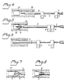
- Fig. 1 is a diagrammatic side view, partly in section, of an embodiment of the device of the invention;
- Fig. 2 is an enlarged detail of the distal end of the device shown in Fig. 1;
- Fig. 3 is a diagrammatic side view of a modification of the instrument shown in Fig. 1 enabling release or extraction of a stent in the opposite direction; and
- Figs. 4 to 8 illustrate the procedure for extracting a stent implanted in the urethra of a patient.
- The device shown in Fig. 1 is generally designated 1 and is principally constituted by two flexible tubes, one
central tube 3 and a surroundingexterior tube 5. Said tubes are substantially coextensive except for the fact that theexterior tube 5 is shorter thancentral tube 3 by a distance at least corresponding to the length of the stent to be implanted. Each oftubes gripping handles Central tube 3 extends throughhandle 9 of the exterior tube for obvious reasons. -
Central tube 3 is, at its distal end, provided with grippingmembers 21. The number of grippingmembers 21 is four and they are evenly distributed around the periphery ofcentral tube 3. In the embodiment shown grippingmembers 21 have a blade-like shape and can be made of a spring steel material. They can be attached tocentral tube 3 by any suitable means, such as welding, riveting or other way of attachment. In a preferred embodiment of theinvention members 21 are cut out of the wall oftube 3 as shown in Fig. 2 and are thus integral with the wall material of said tube. In such embodiment the tube material is suitably a metal or metal alloy having spring properties. - Gripping
members 21 are capable of outward springing movement whenexterior tube 5 is retracted by bringinghandles exterior tube 5 is moved axially forward alongcentral tube 3spring members 21 will fold and will come to close engagement with the exterior surface ofcentral tube 3. - The device shown in Fig. 1 further comprises a viewing device in the form of a
telescope 7 placed insidecentral tube 3 with itsviewing end 8 positioned behindhandle 11. For ease ofoperation handles cavities - As seen from Fig. 2
central tube 3 is provided withopenings 23 suitably positioned for a purpose to be described below. - The device shown in Fig. 1 also includes
seal rings interior tube 3 and thetelescope 7, respectively and inlet means 30, to allow a fluid such as water to be injected to the chamber between the telescope and theinner tube 3 allowing a stream of fluid to rinse the distal end of the telescope for better viewing. - The embodiment shown in Fig. 3 enables implantation and extraction of a stent from the opposite direction. In view of the construction of the stent compression thereof results in axial extension. Therefore, one end of the stent when released will obtain exact location in connection with its implantation, whereas its other end will be located in dependence on the ratio between radial contraction and axial expansion. Therefore, the embodiment of Fig. 3 may be useful when the rear end of the stent is to be correctly positioned in an exact location in a lumen.
- The device shown in Fig. 3 corresponds in predominant parts to that shown in Fig 1, but the distal end of
central tube 3 is provided with an outwardly and backwardlybent end section 25. Moreover, the grippingmembers 21 are directed rearwardly and attached to the distal end ofexterior tube 5 rather than directed forwardly and attached tocentral tube 3 as shown in Fig. 1. In other respects the device shown in Fig. 3 corresponds closely to that shown in Fig. 1. - In the embodiment shown in Fig. 1 for loading purposes the proximal end of a
stent 27 of the type described in US patent 4,655,771 is accomodated beneath grippingmembers 21, whereafterexterior tube 5 will be axially moved forward so as to move grippingmembers 21 radially inwardly to compress the proximal end of thestent 27 and keep it firmly in place in a gap against thecentral tube 3. By further moving theexterior tube 5 axially forward theentire stent 27 will be compressed and kept inside theexterior tube 5. When the loaded device is then inserted into the lumen of a patient, such as into a patient's urethra , not shown in Fig. 1, thetelescope 7 can be axially positioned and by viewing through it the insertion can be closely inspected for establishing the proper location wherestent 27 is to be released. After reaching the correct location for the distal end of the stentexterior tube 5 is moved back byhandle 9. In the position shown in Fig. 1 the proximal end of thestent 27 is released from the gap between the gripping members 22 and thecentral tube 3. By pulling the entire device slightly backwards in relation to the urethra the entire stent is released and by moving theexterior tube 5 forwardly thegripping members 21 will fold inwardly surrounded by the protectingexterior tube 5 and the device can then be removed from the lumen, such as the urethra with the stent completely surrounded byexterior tube 5. - With regard to the embodiment shown in Fig. 3 the procedure is similar but when releasing in this case the proximal end of the
stent 27 will first expand at the desired position of the vessel not shown in this figure by moving thecentral tube 3 axially forward and in the position shown in Fig. 3 thestent 27 is released from the gap between thegripping members 21 and theexterior tube 5. The entire device is then pushed forward in relation to the vessel lumen to completely release thestent 27, whereafter thecentral tube 3 is moved axially backward to the right as seen in Fig. 3 to fold grippingmembers 21 by the movement ofend section 25 against theexterior tube 5 and thus protect the lumen from being affected by the spring members. The device can then be retracted as a whole from the lumen involved. - The procedure used for removing an implanted stent in the urethra 29 will now be described with reference to Figs. 4 to 8.
- Fig. 4 shows a stent implanted into a
vessel 29 of a patient, e.g. the urethra. The device used from extracting the stent from its location within the urethra is of the type shown in Fig. 1. For extracting however, theexterior tube 5 is first kept in a forward position keeping thespring members 21 in a folded position surrounded by the distal end of thetube 5 thus protecting the lumen of the vessel when moving the device. Theencoscope 7 is used for locating the exact position ofstent 27 as seen in Fig. 4. After reaching a position somewhat behindstent 27exterior tube 5 is now moved backwardly, wherebyspring members 21 will be released to engage the inside surface ofurethra 29 with the distal ends just behind the proximal end of thestent 27. Due to the pressure exerted byspring members 21 onto the interior wall of the lumen, the device can be pushed axially forwardly as seen in Fig. 5, whereby thespring members 21 can slide onto the outside of the proximal end ofstent 27. By movingexterior tube 5 to theleft spring members 21 will be folded inwardly thus causing contraction of the proximal end of the stent which will be firmly kept in the gap between the spring members and thecentral tube 3. Further movement ofexterior tube 5 to the left will bring theentire stent 27 together withspring members 21 to a position within the protectingexterior tube 5 as illustrated in Fig. 6. The device can now be removed from the urethra of the patient together withstent 27 in its contracted state. - Fig. 7 and Fig. 8 show a detail of the device according to Fig. 4. When removing a self-expanding stent as described in US patent No. 4,655,771, the
spring members 21 have only to slide a very short distance, such as a few millimeters onto the interior wall of the lumen, as shown in Fig. 7. Fig. 8 shows how the end of this type of stent when contracted by the tip of the spring members will be elongated axially in direction towards the fixed ends of the spring members thus giving sufficient length of fixation in the gap between the spring members and theinterior tube 3 without pushing the device forward. - Also the device of the type shown in Fig. 3 can in a corresponding manner be used as an extractor for implanted stents.
- Even if the device is described in relation to the treatment of urethras it is very suitable for the treatment of many other conduits in the human body. The same devices with optical viewing devices can be successfully used for treatments of such vessels as urethra, the trachea, oesophagus and also some blood vessels.
- It is to be noted that the invention is not limited to the embodiments described herein. Thus, any suitable materials can be used for different parts of the instrument. It is preferred to use flexible materials to reach difficultly accessible locations of different types of lumen in which case also the viewing devices can be exchanged to or combined with any appropriate imaging device such as X-Ray, ultra-sound. Moreover, the invention is useful not only with regard to the type of stent described in US patent No. 4,655,771, although an excellent performance is obtained in relation to such stent.
Claims (15)
- A device for transluminal implantation or extraction of a substantially tubular, radially expandable stent (27), the device comprising a central tube (3) having distal and proximal ends, surrounded by an exterior tube (5) axially displaceable relative to the central tube (3), characterized by a plurality of axially extending gripping members (21) attached to the outer surface of said central tube (3) at the distal end thereof, said members being substantially evenly distributed around the periphery of said tube and capable of outward expanding action of their distal ends when retracting said exterior tube (5) from the distal end of said central tube (3), and capable of forming a gap between said members (21) and the central tube (3) when said exterior tube (5) is moved distally in an axial direction of said central tube (3).
- A device for transluminal implantation or extraction of a substantially tubular, radially expandable stent (27), the device comprising a central tube (3) having proximal and distal ends surrounded by an exterior tube (5) axially displaceable relative to the central tube (3), characterized in that said central tube (3) is provided with a proximally extending end section (25) at the distal end thereof the end section (25) having a larger diameter than the exterior tube (5), and a plurality of axially extending gripping members (21) attached to the outer surface of said exterior tube (5) at the distal end thereof, said members (21) being substantially evenly distributed around the periphery of said tube (5), and being capable of outward expanding action at their rear ends by moving the central tube (3) with its extending end section (25) axially forwardly, and capable of forming a gap between said members (21) and said exterior tube (5) by moving said central tube (3) proximally in an axial direction of said exterior tube (3).
- A device according to claim 1 or 2, further comprising handle means (9; 11) at the rear ends of said tubes (3;5) enabling axial relative movement between said tubes for releasing or folding of said gripping members (21).
- A device according to claim 1, 2 or 3, wherein the number of gripping members (27) is 3 or 4.
- A device according to claim 1, wherein said central tube (3) is provided with radial openings (23) at the distal end thereof enabling proper positioning of the device under operation.
- A device according to claim 1, wherein said central tube (3), at least at the distal end thereof, is made of a transparent material enabling proper positioning of the device under operation.
- A device according to claim 2, wherein one of tubes (3,5) is provided with radial openings at the distal end thereof enabling proper positioning of the device under operation.
- A device according to claim 2, wherein said tubes (3,5) have radial, juxtaposed openings at the distal end thereof enabling proper positioning of the device under operation.
- A device according to claim 2, wherein said tubes (3,5), at least at the distal end thereof, are made of transparent material enabling proper positioning of the device under operation.
- A device according to any of claims 5 to 9, further comprising viewing means such as an endoscope or a telescope (7) positioned inside the central tube (3) and axially displaceable therein.
- A device according to any preceding claim, wherein the concentric members (3,5,7) are made of flexible materials enabling bending of the device under operation.
- A device according to any preceding claim, wherein said gripping members are constituted by springing members (21) capable of outward springing action when released.
- The combination of the device according to claim 1 and a substantially tubular, radially expandable stent (27), characterized in that said stent (27) is positionable between said gripping members (21) and said central tube (3) is in a contracted state.
- The combination of the device according to claim 2 and a substantially tubular, radially expandable stent, characterized in that said stent (27) is positionable between said gripping members (21) and said exterior tube (5) is in a contracted state.
- The combination according to claim 13 or 14, wherein said stent (27) is of the self-expanding type.
Priority Applications (1)
| Application Number | Priority Date | Filing Date | Title |
|---|---|---|---|
| AT89850313T ATE82145T1 (en) | 1988-09-28 | 1989-09-22 | DEVICE FOR TRANSLUMINAL IMPLANTATION OR EXTRACTION. |
Applications Claiming Priority (2)
| Application Number | Priority Date | Filing Date | Title |
|---|---|---|---|
| SE8803444 | 1988-09-28 | ||
| SE8803444A SE8803444D0 (en) | 1988-09-28 | 1988-09-28 | A DEVICE FOR TRANSLUMINAL IMPLANTATION OR EXTRACTION |
Publications (2)
| Publication Number | Publication Date |
|---|---|
| EP0364420A1 EP0364420A1 (en) | 1990-04-18 |
| EP0364420B1 true EP0364420B1 (en) | 1992-11-11 |
Family
ID=20373472
Family Applications (1)
| Application Number | Title | Priority Date | Filing Date |
|---|---|---|---|
| EP89850313A Expired - Lifetime EP0364420B1 (en) | 1988-09-28 | 1989-09-22 | A device for transluminal implantation or extraction |
Country Status (7)
| Country | Link |
|---|---|
| US (1) | US4990151A (en) |
| EP (1) | EP0364420B1 (en) |
| JP (1) | JP2858461B2 (en) |
| AT (1) | ATE82145T1 (en) |
| DE (1) | DE68903466T2 (en) |
| ES (1) | ES2035645T3 (en) |
| SE (1) | SE8803444D0 (en) |
Cited By (18)
| Publication number | Priority date | Publication date | Assignee | Title |
|---|---|---|---|---|
| EP0466412A1 (en) * | 1990-07-09 | 1992-01-15 | Wilson-Cook Medical Inc. | Device for retrieving stents |
| WO1992020292A1 (en) * | 1991-05-24 | 1992-11-26 | Heidmueller Harald | Surgical appliance |
| EP0518839A2 (en) * | 1991-06-14 | 1992-12-16 | Ams Medinvent S.A. | Transluminal implantation or extraction device |
| EP0518838A1 (en) * | 1991-06-14 | 1992-12-16 | Ams Medinvent S.A. | Transluminal implantation device |
| EP0557963A1 (en) * | 1992-02-24 | 1993-09-01 | United States Surgical Corporation | Resilient arm mesh deployer |
| WO1993017636A1 (en) * | 1992-03-12 | 1993-09-16 | Laboratoire Perouse Implant | Expansible endoprosthesis for human or animal tubular organs and tool for positioning said endoprosthesis |
| FR2688688A1 (en) * | 1992-03-12 | 1993-09-24 | Richard Thierry | Tool for fitting an autoexpansible endoprosthesis for human or animal tubular organ |
| US5411507A (en) * | 1993-01-08 | 1995-05-02 | Richard Wolf Gmbh | Instrument for implanting and extracting stents |
| US5474563A (en) * | 1993-03-25 | 1995-12-12 | Myler; Richard | Cardiovascular stent and retrieval apparatus |
| US5643309A (en) * | 1993-03-25 | 1997-07-01 | Myler; Richard | Cardiovascular stent and retrieval apparatus |
| US5683451A (en) * | 1994-06-08 | 1997-11-04 | Cardiovascular Concepts, Inc. | Apparatus and methods for deployment release of intraluminal prostheses |
| US5709703A (en) * | 1995-11-14 | 1998-01-20 | Schneider (Europe) A.G. | Stent delivery device and method for manufacturing same |
| US5824041A (en) * | 1994-06-08 | 1998-10-20 | Medtronic, Inc. | Apparatus and methods for placement and repositioning of intraluminal prostheses |
| US5941895A (en) * | 1996-09-04 | 1999-08-24 | Hemodynamics, Inc. | Cardiovascular stent and retrieval apparatus |
| US6146389A (en) * | 1998-04-23 | 2000-11-14 | Boston Scientific Corporation | Stent deployment device and method for deploying a stent |
| US6740105B2 (en) | 2001-11-23 | 2004-05-25 | Mind Guard Ltd. | Expandable delivery appliance particularly for delivering intravascular devices |
| US7731654B2 (en) | 2005-05-13 | 2010-06-08 | Merit Medical Systems, Inc. | Delivery device with viewing window and associated method |
| US8317854B1 (en) | 1994-06-08 | 2012-11-27 | Medtronic Vascular, Inc. | Apparatus and methods for endoluminal graft placement |
Families Citing this family (285)
| Publication number | Priority date | Publication date | Assignee | Title |
|---|---|---|---|---|
| US5782903A (en) * | 1987-10-19 | 1998-07-21 | Medtronic, Inc. | Intravascular stent and method |
| US5662701A (en) * | 1989-08-18 | 1997-09-02 | Endovascular Instruments, Inc. | Anti-stenotic method and product for occluded and partially occluded arteries |
| US5571169A (en) * | 1993-06-07 | 1996-11-05 | Endovascular Instruments, Inc. | Anti-stenotic method and product for occluded and partially occluded arteries |
| US5549615A (en) * | 1989-11-11 | 1996-08-27 | Vascomed Institut Fur Kathetertechnologie Gmbh | Method and apparatus for extracting pacemaker electrodes embedded in the heart |
| US6238431B1 (en) * | 1990-03-09 | 2001-05-29 | Pannayiotis J. Asimacopoulos | Extractable variably controlled diameter stent and method of using the same |
| US5725522A (en) * | 1990-06-15 | 1998-03-10 | Rare Earth Medical, Inc. | Laser suturing of biological materials |
| US5540677A (en) * | 1990-06-15 | 1996-07-30 | Rare Earth Medical, Inc. | Endoscopic systems for photoreactive suturing of biological materials |
| US5159920A (en) * | 1990-06-18 | 1992-11-03 | Mentor Corporation | Scope and stent system |
| US5591172A (en) * | 1991-06-14 | 1997-01-07 | Ams Medinvent S.A. | Transluminal implantation device |
| WO1993006792A1 (en) * | 1991-10-04 | 1993-04-15 | Scimed Life Systems, Inc. | Biodegradable drug delivery vascular stent |
| US7101392B2 (en) * | 1992-03-31 | 2006-09-05 | Boston Scientific Corporation | Tubular medical endoprostheses |
| US6497709B1 (en) | 1992-03-31 | 2002-12-24 | Boston Scientific Corporation | Metal medical device |
| JPH07505316A (en) | 1992-03-31 | 1995-06-15 | ボストン サイエンティフィック コーポレーション | medical wire |
| US5540712A (en) * | 1992-05-01 | 1996-07-30 | Nitinol Medical Technologies, Inc. | Stent and method and apparatus for forming and delivering the same |
| DE4220295A1 (en) * | 1992-06-20 | 1993-12-23 | Angiomed Ag | Device for correcting the position of a stent |
| US5496365A (en) * | 1992-07-02 | 1996-03-05 | Sgro; Jean-Claude | Autoexpandable vascular endoprosthesis |
| US5312417A (en) * | 1992-07-29 | 1994-05-17 | Wilk Peter J | Laparoscopic cannula assembly and associated method |
| US5707376A (en) * | 1992-08-06 | 1998-01-13 | William Cook Europe A/S | Stent introducer and method of use |
| ATE149325T1 (en) * | 1992-10-12 | 1997-03-15 | Schneider Europ Ag | CATHETER WITH A VESSEL SUPPORT |
| US5630840A (en) | 1993-01-19 | 1997-05-20 | Schneider (Usa) Inc | Clad composite stent |
| US20050059889A1 (en) * | 1996-10-16 | 2005-03-17 | Schneider (Usa) Inc., A Minnesota Corporation | Clad composite stent |
| CA2152594C (en) * | 1993-01-19 | 1998-12-01 | David W. Mayer | Clad composite stent |
| US5843167A (en) * | 1993-04-22 | 1998-12-01 | C. R. Bard, Inc. | Method and apparatus for recapture of hooked endoprosthesis |
| US5282472A (en) * | 1993-05-11 | 1994-02-01 | Companion John A | System and process for the detection, evaluation and treatment of prostate and urinary problems |
| US5480423A (en) * | 1993-05-20 | 1996-01-02 | Boston Scientific Corporation | Prosthesis delivery |
| US5391172A (en) * | 1993-05-24 | 1995-02-21 | Advanced Cardiovascular Systems, Inc. | Stent delivery system with coaxial catheter handle |
| US5279548A (en) * | 1993-05-27 | 1994-01-18 | Essig Mitchell N | Peritoneal surgical method |
| US5913897A (en) * | 1993-09-16 | 1999-06-22 | Cordis Corporation | Endoprosthesis having multiple bridging junctions and procedure |
| EP0657147B1 (en) * | 1993-11-04 | 1999-08-04 | C.R. Bard, Inc. | Non-migrating vascular prosthesis |
| US5476505A (en) * | 1993-11-18 | 1995-12-19 | Advanced Cardiovascular Systems, Inc. | Coiled stent and delivery system |
| US5591196A (en) * | 1994-02-10 | 1997-01-07 | Endovascular Systems, Inc. | Method for deployment of radially expandable stents |
| US6039749A (en) | 1994-02-10 | 2000-03-21 | Endovascular Systems, Inc. | Method and apparatus for deploying non-circular stents and graftstent complexes |
| US5645083A (en) * | 1994-02-10 | 1997-07-08 | Essig; Mitchell N. | Peritoneal surgical method |
| US5443477A (en) * | 1994-02-10 | 1995-08-22 | Stentco, Inc. | Apparatus and method for deployment of radially expandable stents by a mechanical linkage |
| US5507769A (en) * | 1994-10-18 | 1996-04-16 | Stentco, Inc. | Method and apparatus for forming an endoluminal bifurcated graft |
| US6001123A (en) * | 1994-04-01 | 1999-12-14 | Gore Enterprise Holdings Inc. | Folding self-expandable intravascular stent-graft |
| US6165210A (en) * | 1994-04-01 | 2000-12-26 | Gore Enterprise Holdings, Inc. | Self-expandable helical intravascular stent and stent-graft |
| US5476510A (en) * | 1994-04-21 | 1995-12-19 | Medtronic, Inc. | Holder for heart valve |
| US5456694A (en) * | 1994-05-13 | 1995-10-10 | Stentco, Inc. | Device for delivering and deploying intraluminal devices |
| US6331188B1 (en) | 1994-08-31 | 2001-12-18 | Gore Enterprise Holdings, Inc. | Exterior supported self-expanding stent-graft |
| US6015429A (en) * | 1994-09-08 | 2000-01-18 | Gore Enterprise Holdings, Inc. | Procedures for introducing stents and stent-grafts |
| NL9401571A (en) * | 1994-09-27 | 1996-05-01 | Industrial Res Bv | System for removing a stent from a body vessel. |
| US5749851A (en) | 1995-03-02 | 1998-05-12 | Scimed Life Systems, Inc. | Stent installation method using balloon catheter having stepped compliance curve |
| US5643278A (en) * | 1995-04-06 | 1997-07-01 | Leocor, Inc. | Stent delivery system |
| AU711503B2 (en) * | 1995-06-01 | 1999-10-14 | Meadox Medicals, Inc. | Implantable intraluminal prosthesis |
| US5702418A (en) * | 1995-09-12 | 1997-12-30 | Boston Scientific Corporation | Stent delivery system |
| WO1997014375A1 (en) * | 1995-10-20 | 1997-04-24 | Bandula Wijay | Vascular stent |
| FR2740024B1 (en) * | 1995-10-23 | 1998-01-02 | Berberian Jean Pierre | PROSTHESES OF THE URINARY TREE WITH THEIR APPLICATORS |
| US5741293A (en) * | 1995-11-28 | 1998-04-21 | Wijay; Bandula | Locking stent |
| US6042605A (en) * | 1995-12-14 | 2000-03-28 | Gore Enterprose Holdings, Inc. | Kink resistant stent-graft |
| EP0866677A4 (en) | 1995-12-14 | 1999-10-27 | Prograft Medical Inc | Stent-graft deployment apparatus and method |
| US6203569B1 (en) | 1996-01-04 | 2001-03-20 | Bandula Wijay | Flexible stent |
| EP0879028B1 (en) * | 1996-02-06 | 1999-10-27 | Michael Havel | Vascular prosthesis |
| FR2744625B1 (en) * | 1996-02-14 | 1998-05-07 | Bfl Sa | URETRAL SHAPE MEMORY PROSTHESIS AND DELIVERY DEVICE |
| US5749921A (en) * | 1996-02-20 | 1998-05-12 | Medtronic, Inc. | Apparatus and methods for compression of endoluminal prostheses |
| US5690643A (en) * | 1996-02-20 | 1997-11-25 | Leocor, Incorporated | Stent delivery system |
| US5707387A (en) * | 1996-03-25 | 1998-01-13 | Wijay; Bandula | Flexible stent |
| US5868754A (en) * | 1996-06-12 | 1999-02-09 | Target Therapeutics, Inc. | Medical retrieval device |
| DE69722720T2 (en) * | 1996-07-24 | 2004-05-13 | Cordis Corp., Miami Lakes | Balloon catheter and method of use |
| EP0829242A1 (en) * | 1996-08-19 | 1998-03-18 | Schneider (Europe) Ag | Removal device for an implanted endoprothesis |
| US7749585B2 (en) * | 1996-10-08 | 2010-07-06 | Alan Zamore | Reduced profile medical balloon element |
| US5843090A (en) * | 1996-11-05 | 1998-12-01 | Schneider (Usa) Inc. | Stent delivery device |
| US5860998A (en) * | 1996-11-25 | 1999-01-19 | C. R. Bard, Inc. | Deployment device for tubular expandable prosthesis |
| US6551350B1 (en) * | 1996-12-23 | 2003-04-22 | Gore Enterprise Holdings, Inc. | Kink resistant bifurcated prosthesis |
| US6352561B1 (en) * | 1996-12-23 | 2002-03-05 | W. L. Gore & Associates | Implant deployment apparatus |
| US5925061A (en) * | 1997-01-13 | 1999-07-20 | Gore Enterprise Holdings, Inc. | Low profile vascular stent |
| US5957974A (en) * | 1997-01-23 | 1999-09-28 | Schneider (Usa) Inc | Stent graft with braided polymeric sleeve |
| GB2324729B (en) | 1997-04-30 | 2002-01-02 | Bradford Hospitals Nhs Trust | Lung treatment device |
| CA2235911C (en) * | 1997-05-27 | 2003-07-29 | Schneider (Usa) Inc. | Stent and stent-graft for treating branched vessels |
| US5906641A (en) * | 1997-05-27 | 1999-05-25 | Schneider (Usa) Inc | Bifurcated stent graft |
| EP0891752B1 (en) | 1997-07-17 | 2005-01-12 | Schneider (Europe) GmbH | Stent and method for manufacturing such a stent |
| US5906619A (en) | 1997-07-24 | 1999-05-25 | Medtronic, Inc. | Disposable delivery device for endoluminal prostheses |
| US6070589A (en) | 1997-08-01 | 2000-06-06 | Teramed, Inc. | Methods for deploying bypass graft stents |
| US5824059A (en) * | 1997-08-05 | 1998-10-20 | Wijay; Bandula | Flexible stent |
| EP1039864B1 (en) * | 1997-11-14 | 2006-12-27 | Boston Scientific Limited | Multi-sheath delivery catheter |
| US6533807B2 (en) | 1998-02-05 | 2003-03-18 | Medtronic, Inc. | Radially-expandable stent and delivery system |
| US6280467B1 (en) | 1998-02-26 | 2001-08-28 | World Medical Manufacturing Corporation | Delivery system for deployment and endovascular assembly of a multi-stage stented graft |
| US7491232B2 (en) | 1998-09-18 | 2009-02-17 | Aptus Endosystems, Inc. | Catheter-based fastener implantation apparatus and methods with implantation force resolution |
| US6887268B2 (en) | 1998-03-30 | 2005-05-03 | Cordis Corporation | Extension prosthesis for an arterial repair |
| US6290731B1 (en) | 1998-03-30 | 2001-09-18 | Cordis Corporation | Aortic graft having a precursor gasket for repairing an abdominal aortic aneurysm |
| US6656215B1 (en) | 2000-11-16 | 2003-12-02 | Cordis Corporation | Stent graft having an improved means for attaching a stent to a graft |
| US6520983B1 (en) * | 1998-03-31 | 2003-02-18 | Scimed Life Systems, Inc. | Stent delivery system |
| US6264689B1 (en) | 1998-03-31 | 2001-07-24 | Scimed Life Systems, Incorporated | Low profile medical stent |
| US6143021A (en) * | 1998-07-10 | 2000-11-07 | American Medical Systems, Inc. | Stent placement instrument and method of assembly |
| US6099533A (en) * | 1998-08-11 | 2000-08-08 | Ajida Technologies, Inc. | Apparatus and method for localizing prosthesis deployed in a body lumen |
| US7314477B1 (en) | 1998-09-25 | 2008-01-01 | C.R. Bard Inc. | Removable embolus blood clot filter and filter delivery unit |
| US6203550B1 (en) | 1998-09-30 | 2001-03-20 | Medtronic, Inc. | Disposable delivery device for endoluminal prostheses |
| US6214036B1 (en) | 1998-11-09 | 2001-04-10 | Cordis Corporation | Stent which is easily recaptured and repositioned within the body |
| US6340366B2 (en) | 1998-12-08 | 2002-01-22 | Bandula Wijay | Stent with nested or overlapping rings |
| US7018401B1 (en) | 1999-02-01 | 2006-03-28 | Board Of Regents, The University Of Texas System | Woven intravascular devices and methods for making the same and apparatus for delivery of the same |
| US6187016B1 (en) | 1999-09-14 | 2001-02-13 | Daniel G. Hedges | Stent retrieval device |
| US6270525B1 (en) | 1999-09-23 | 2001-08-07 | Cordis Corporation | Precursor stent gasket for receiving bilateral grafts having controlled contralateral guidewire access |
| US20030070683A1 (en) * | 2000-03-04 | 2003-04-17 | Deem Mark E. | Methods and devices for use in performing pulmonary procedures |
| US8474460B2 (en) * | 2000-03-04 | 2013-07-02 | Pulmonx Corporation | Implanted bronchial isolation devices and methods |
| US6679264B1 (en) * | 2000-03-04 | 2004-01-20 | Emphasys Medical, Inc. | Methods and devices for use in performing pulmonary procedures |
| US7201770B2 (en) * | 2000-03-21 | 2007-04-10 | Cordis Corporation | Everting balloon stent delivery system having tapered leading edge |
| CA2408923A1 (en) * | 2000-05-18 | 2001-11-22 | David Peter Shaw | Bronchiopulmonary occlusion devices and lung volume reduction methods |
| US6843802B1 (en) | 2000-11-16 | 2005-01-18 | Cordis Corporation | Delivery apparatus for a self expanding retractable stent |
| US7314483B2 (en) * | 2000-11-16 | 2008-01-01 | Cordis Corp. | Stent graft with branch leg |
| US7229472B2 (en) | 2000-11-16 | 2007-06-12 | Cordis Corporation | Thoracic aneurysm repair prosthesis and system |
| US7267685B2 (en) | 2000-11-16 | 2007-09-11 | Cordis Corporation | Bilateral extension prosthesis and method of delivery |
| US6942692B2 (en) | 2000-11-16 | 2005-09-13 | Cordis Corporation | Supra-renal prosthesis and renal artery bypass |
| US6764504B2 (en) * | 2001-01-04 | 2004-07-20 | Scimed Life Systems, Inc. | Combined shaped balloon and stent protector |
| US6699274B2 (en) * | 2001-01-22 | 2004-03-02 | Scimed Life Systems, Inc. | Stent delivery system and method of manufacturing same |
| US6743210B2 (en) * | 2001-02-15 | 2004-06-01 | Scimed Life Systems, Inc. | Stent delivery catheter positioning device |
| US7798147B2 (en) * | 2001-03-02 | 2010-09-21 | Pulmonx Corporation | Bronchial flow control devices with membrane seal |
| US7011094B2 (en) * | 2001-03-02 | 2006-03-14 | Emphasys Medical, Inc. | Bronchial flow control devices and methods of use |
| US6592549B2 (en) | 2001-03-14 | 2003-07-15 | Scimed Life Systems, Inc. | Rapid exchange stent delivery system and associated components |
| US20050021123A1 (en) | 2001-04-30 | 2005-01-27 | Jurgen Dorn | Variable speed self-expanding stent delivery system and luer locking connector |
| US6821291B2 (en) | 2001-06-01 | 2004-11-23 | Ams Research Corporation | Retrievable stent and method of use thereof |
| US6926732B2 (en) | 2001-06-01 | 2005-08-09 | Ams Research Corporation | Stent delivery device and method |
| US6645238B2 (en) * | 2001-07-09 | 2003-11-11 | Scimed Life Systems, Inc. | Skids stent delivery system |
| US6863683B2 (en) | 2001-09-19 | 2005-03-08 | Abbott Laboratoris Vascular Entities Limited | Cold-molding process for loading a stent onto a stent delivery system |
| DE10148185B4 (en) * | 2001-09-28 | 2005-08-11 | Alveolus, Inc. | Instrument for implanting vascular prostheses |
| US6866669B2 (en) * | 2001-10-12 | 2005-03-15 | Cordis Corporation | Locking handle deployment mechanism for medical device and method |
| US6939352B2 (en) | 2001-10-12 | 2005-09-06 | Cordis Corporation | Handle deployment mechanism for medical device and method |
| US20050177180A1 (en) | 2001-11-28 | 2005-08-11 | Aptus Endosystems, Inc. | Devices, systems, and methods for supporting tissue and/or structures within a hollow body organ |
| JP4405262B2 (en) * | 2001-11-28 | 2010-01-27 | アプタス エンドシステムズ, インコーポレイテッド | Intravascular aneurysm repair system |
| US20090112302A1 (en) * | 2001-11-28 | 2009-04-30 | Josh Stafford | Devices, systems, and methods for endovascular staple and/or prosthesis delivery and implantation |
| US8231639B2 (en) | 2001-11-28 | 2012-07-31 | Aptus Endosystems, Inc. | Systems and methods for attaching a prosthesis within a body lumen or hollow organ |
| US7828838B2 (en) * | 2001-11-28 | 2010-11-09 | Aptus Endosystems, Inc. | Devices, systems, and methods for prosthesis delivery and implantation, including a prosthesis assembly |
| US20070073389A1 (en) | 2001-11-28 | 2007-03-29 | Aptus Endosystems, Inc. | Endovascular aneurysm devices, systems, and methods |
| US7147657B2 (en) * | 2003-10-23 | 2006-12-12 | Aptus Endosystems, Inc. | Prosthesis delivery systems and methods |
| US9320503B2 (en) | 2001-11-28 | 2016-04-26 | Medtronic Vascular, Inc. | Devices, system, and methods for guiding an operative tool into an interior body region |
| US7326237B2 (en) * | 2002-01-08 | 2008-02-05 | Cordis Corporation | Supra-renal anchoring prosthesis |
| US9204956B2 (en) | 2002-02-20 | 2015-12-08 | C. R. Bard, Inc. | IVC filter with translating hooks |
| US6989024B2 (en) * | 2002-02-28 | 2006-01-24 | Counter Clockwise, Inc. | Guidewire loaded stent for delivery through a catheter |
| US6866679B2 (en) | 2002-03-12 | 2005-03-15 | Ev3 Inc. | Everting stent and stent delivery system |
| US20030216804A1 (en) * | 2002-05-14 | 2003-11-20 | Debeer Nicholas C. | Shape memory polymer stent |
| AU2003256798A1 (en) * | 2002-07-26 | 2004-02-16 | Emphasys Medical, Inc. | Bronchial flow control devices with membrane seal |
| WO2004030571A2 (en) * | 2002-09-30 | 2004-04-15 | Board Of Regents, The University Of Texas System | Stent delivery system and method of use |
| US20040093056A1 (en) * | 2002-10-26 | 2004-05-13 | Johnson Lianw M. | Medical appliance delivery apparatus and method of use |
| US8449594B2 (en) | 2002-11-01 | 2013-05-28 | Marc-Alan Levine | Method and apparatus for caged stent delivery |
| US7169172B2 (en) * | 2002-11-01 | 2007-01-30 | Counter Clockwise, Inc. | Method and apparatus for caged stent delivery |
| GB0225427D0 (en) * | 2002-11-01 | 2002-12-11 | Baig Mirza K | Stent retrieval device |
| US7814912B2 (en) * | 2002-11-27 | 2010-10-19 | Pulmonx Corporation | Delivery methods and devices for implantable bronchial isolation devices |
| US7611528B2 (en) * | 2003-01-24 | 2009-11-03 | Medtronic Vascular, Inc. | Stent-graft delivery system |
| US20040193179A1 (en) * | 2003-03-26 | 2004-09-30 | Cardiomind, Inc. | Balloon catheter lumen based stent delivery systems |
| US20050209672A1 (en) * | 2004-03-02 | 2005-09-22 | Cardiomind, Inc. | Sliding restraint stent delivery systems |
| US7771463B2 (en) * | 2003-03-26 | 2010-08-10 | Ton Dai T | Twist-down implant delivery technologies |
| ES2346059T3 (en) * | 2003-03-26 | 2010-10-08 | Biosensors International Group Ltd. | IMPLANT SUPPLY CATHETER WITH ELECTROLYTICALLY EROSIONABLE JOINTS. |
| US7637934B2 (en) * | 2003-03-31 | 2009-12-29 | Merit Medical Systems, Inc. | Medical appliance optical delivery and deployment apparatus and method |
| US20040267348A1 (en) * | 2003-04-11 | 2004-12-30 | Gunderson Richard C. | Medical device delivery systems |
| US7473271B2 (en) * | 2003-04-11 | 2009-01-06 | Boston Scientific Scimed, Inc. | Stent delivery system with securement and deployment accuracy |
| JP2007500584A (en) * | 2003-06-12 | 2007-01-18 | シー・アール・バード・インク | Stent delivery catheter |
| US8292943B2 (en) | 2003-09-03 | 2012-10-23 | Bolton Medical, Inc. | Stent graft with longitudinal support member |
| US20080264102A1 (en) | 2004-02-23 | 2008-10-30 | Bolton Medical, Inc. | Sheath Capture Device for Stent Graft Delivery System and Method for Operating Same |
| US11596537B2 (en) | 2003-09-03 | 2023-03-07 | Bolton Medical, Inc. | Delivery system and method for self-centering a proximal end of a stent graft |
| US9198786B2 (en) | 2003-09-03 | 2015-12-01 | Bolton Medical, Inc. | Lumen repair device with capture structure |
| US20070198078A1 (en) | 2003-09-03 | 2007-08-23 | Bolton Medical, Inc. | Delivery system and method for self-centering a Proximal end of a stent graft |
| US7763063B2 (en) | 2003-09-03 | 2010-07-27 | Bolton Medical, Inc. | Self-aligning stent graft delivery system, kit, and method |
| US11259945B2 (en) | 2003-09-03 | 2022-03-01 | Bolton Medical, Inc. | Dual capture device for stent graft delivery system and method for capturing a stent graft |
| US8500792B2 (en) | 2003-09-03 | 2013-08-06 | Bolton Medical, Inc. | Dual capture device for stent graft delivery system and method for capturing a stent graft |
| US7967829B2 (en) * | 2003-10-09 | 2011-06-28 | Boston Scientific Scimed, Inc. | Medical device delivery system |
| US20050125050A1 (en) * | 2003-12-04 | 2005-06-09 | Wilson Cook Medical Incorporated | Biliary stent introducer system |
| US20050131515A1 (en) | 2003-12-16 | 2005-06-16 | Cully Edward H. | Removable stent-graft |
| US7887574B2 (en) * | 2003-12-23 | 2011-02-15 | Scimed Life Systems, Inc. | Stent delivery catheter |
| US7162030B2 (en) | 2003-12-23 | 2007-01-09 | Nokia Corporation | Communication device with rotating housing |
| US8535366B2 (en) | 2004-01-08 | 2013-09-17 | Merit Medical Systems, Inc. | Implantable device delivery system handle and method of use |
| US7468070B2 (en) * | 2004-01-23 | 2008-12-23 | Boston Scientific Scimed, Inc. | Stent delivery catheter |
| US20050178389A1 (en) * | 2004-01-27 | 2005-08-18 | Shaw David P. | Disease indications for selective endobronchial lung region isolation |
| US8206684B2 (en) * | 2004-02-27 | 2012-06-26 | Pulmonx Corporation | Methods and devices for blocking flow through collateral pathways in the lung |
| US7651521B2 (en) * | 2004-03-02 | 2010-01-26 | Cardiomind, Inc. | Corewire actuated delivery system with fixed distal stent-carrying extension |
| EP1722716B1 (en) * | 2004-03-08 | 2017-08-16 | Pulmonx, Inc | Implanted bronchial isolation devices and methods |
| US20050273150A1 (en) * | 2004-03-31 | 2005-12-08 | Howell Douglas D | Stent introducer system |
| US20060041270A1 (en) * | 2004-05-07 | 2006-02-23 | Jay Lenker | Medical access sheath |
| US20060030863A1 (en) * | 2004-07-21 | 2006-02-09 | Fields Antony J | Implanted bronchial isolation device delivery devices and methods |
| US7704267B2 (en) | 2004-08-04 | 2010-04-27 | C. R. Bard, Inc. | Non-entangling vena cava filter |
| US7771472B2 (en) * | 2004-11-19 | 2010-08-10 | Pulmonx Corporation | Bronchial flow control devices and methods of use |
| US8025668B2 (en) * | 2005-04-28 | 2011-09-27 | C. R. Bard, Inc. | Medical device removal system |
| JP5102201B2 (en) | 2005-05-12 | 2012-12-19 | シー・アール・バード・インコーポレーテッド | Removable embolic clot filter |
| WO2006124822A1 (en) * | 2005-05-13 | 2006-11-23 | Alveolus, Inc. | Delivery device allowing visual inspection of an intravascular site |
| US20070073379A1 (en) * | 2005-09-29 | 2007-03-29 | Chang Jean C | Stent delivery system |
| US8038704B2 (en) * | 2005-07-27 | 2011-10-18 | Paul S. Sherburne | Stent and other objects removal from a body |
| JP4851522B2 (en) | 2005-08-09 | 2012-01-11 | シー・アール・バード・インコーポレーテッド | Insertion type thrombus filter and delivery system |
| CA2619363C (en) | 2005-08-17 | 2014-07-15 | C.R. Bard, Inc. | Variable speed stent delivery system |
| US20070055339A1 (en) * | 2005-08-23 | 2007-03-08 | George William R | Staged stent delivery systems |
| CN101466316B (en) | 2005-10-20 | 2012-06-27 | 阿普特斯内系统公司 | Devices systems and methods for prosthesis delivery and implantation including the use of a fastener tool |
| US20070100414A1 (en) * | 2005-11-02 | 2007-05-03 | Cardiomind, Inc. | Indirect-release electrolytic implant delivery systems |
| JP2009519731A (en) | 2005-11-18 | 2009-05-21 | シー・アール・バード・インコーポレイテツド | Vena cava filter with filament |
| US11026822B2 (en) | 2006-01-13 | 2021-06-08 | C. R. Bard, Inc. | Stent delivery system |
| US8808346B2 (en) * | 2006-01-13 | 2014-08-19 | C. R. Bard, Inc. | Stent delivery system |
| US20070185373A1 (en) * | 2006-02-03 | 2007-08-09 | Ethicon Endo-Surgery, Inc. | Gastric band introduction device |
| WO2007095031A2 (en) * | 2006-02-13 | 2007-08-23 | Bay Street Medical, Inc. | System for delivering a stent |
| US20070219618A1 (en) * | 2006-03-17 | 2007-09-20 | Cully Edward H | Endoprosthesis having multiple helically wound flexible framework elements |
| US20070239254A1 (en) * | 2006-04-07 | 2007-10-11 | Chris Chia | System for percutaneous delivery and removal of a prosthetic valve |
| US10188496B2 (en) | 2006-05-02 | 2019-01-29 | C. R. Bard, Inc. | Vena cava filter formed from a sheet |
| US9326842B2 (en) * | 2006-06-05 | 2016-05-03 | C. R . Bard, Inc. | Embolus blood clot filter utilizable with a single delivery system or a single retrieval system in one of a femoral or jugular access |
| US8333000B2 (en) | 2006-06-19 | 2012-12-18 | Advanced Cardiovascular Systems, Inc. | Methods for improving stent retention on a balloon catheter |
| WO2008016578A2 (en) | 2006-07-31 | 2008-02-07 | Cartledge Richard G | Sealable endovascular implants and methods for their use |
| US9585743B2 (en) | 2006-07-31 | 2017-03-07 | Edwards Lifesciences Cardiaq Llc | Surgical implant devices and methods for their manufacture and use |
| US9408607B2 (en) * | 2009-07-02 | 2016-08-09 | Edwards Lifesciences Cardiaq Llc | Surgical implant devices and methods for their manufacture and use |
| US8454684B2 (en) * | 2006-08-02 | 2013-06-04 | Medtronic, Inc. | Heart valve holder for use in valve implantation procedures |
| US7871432B2 (en) * | 2006-08-02 | 2011-01-18 | Medtronic, Inc. | Heart valve holder for use in valve implantation procedures |
| GB0615658D0 (en) | 2006-08-07 | 2006-09-13 | Angiomed Ag | Hand-held actuator device |
| WO2008027293A2 (en) * | 2006-08-25 | 2008-03-06 | Emphasys Medical, Inc. | Bronchial isolation devices for placement in short lumens |
| JP2010504820A (en) * | 2006-09-28 | 2010-02-18 | クック・インコーポレイテッド | Apparatus and method for repairing a thoracic aortic aneurysm |
| KR101659197B1 (en) | 2006-10-22 | 2016-09-22 | 이데브 테크놀로지스, 아이엔씨. | Devices and methods for stent advancement |
| CN103767810B (en) | 2006-10-22 | 2016-06-15 | Idev科技公司 | From the manufacturing process of extendable bracket |
| US20080221666A1 (en) * | 2006-12-15 | 2008-09-11 | Cardiomind, Inc. | Stent systems |
| CA2676787A1 (en) * | 2007-02-05 | 2008-08-14 | Boston Scientific Limited | System with catheter system and an adaptor comprising a friction reducing sleeve, and methods of use |
| US7815601B2 (en) * | 2007-02-05 | 2010-10-19 | Boston Scientific Scimed, Inc. | Rapid exchange enteral stent delivery system |
| US20080255654A1 (en) * | 2007-03-22 | 2008-10-16 | Bay Street Medical | System for delivering a stent |
| US20080300667A1 (en) * | 2007-05-31 | 2008-12-04 | Bay Street Medical | System for delivering a stent |
| GB0713497D0 (en) | 2007-07-11 | 2007-08-22 | Angiomed Ag | Device for catheter sheath retraction |
| US9144508B2 (en) | 2007-07-19 | 2015-09-29 | Back Bay Medical Inc. | Radially expandable stent |
| US9814611B2 (en) | 2007-07-31 | 2017-11-14 | Edwards Lifesciences Cardiaq Llc | Actively controllable stent, stent graft, heart valve and method of controlling same |
| US9566178B2 (en) | 2010-06-24 | 2017-02-14 | Edwards Lifesciences Cardiaq Llc | Actively controllable stent, stent graft, heart valve and method of controlling same |
| US8500773B2 (en) * | 2007-08-01 | 2013-08-06 | Boston Scientific Scimed, Inc. | Spring detach joint for delivering a detachable implantable device |
| US11589880B2 (en) | 2007-12-20 | 2023-02-28 | Angiodynamics, Inc. | System and methods for removing undesirable material within a circulatory system utilizing during a surgical procedure |
| US8734374B2 (en) | 2007-12-20 | 2014-05-27 | Angiodynamics, Inc. | Systems and methods for removing undesirable material within a circulatory system during a surgical procedure |
| US10517617B2 (en) | 2007-12-20 | 2019-12-31 | Angiodynamics, Inc. | Systems and methods for removing undesirable material within a circulatory system utilizing a balloon catheter |
| US8758421B2 (en) * | 2008-01-30 | 2014-06-24 | Boston Scientific Scimed, Inc. | Medical systems and related methods |
| US20090287145A1 (en) * | 2008-05-15 | 2009-11-19 | Altura Interventional, Inc. | Devices and methods for treatment of abdominal aortic aneurysms |
| US8876876B2 (en) * | 2008-06-06 | 2014-11-04 | Back Bay Medical Inc. | Prosthesis and delivery system |
| ES2749741T3 (en) | 2008-06-30 | 2020-03-23 | Bolton Medical Inc | Abdominal aortic aneurysm systems |
| US8187313B2 (en) * | 2008-08-01 | 2012-05-29 | Boston Scientific Scimed, Inc. | Bifurcation catheter assembly side catheter branch construction and methods |
| DK2313032T3 (en) | 2008-08-19 | 2021-02-15 | Merit Medical Systems Inc | SUPPLY DEVICE WITH A PROTECTIVE ELEMENT |
| US8034095B2 (en) | 2008-08-29 | 2011-10-11 | Cook Medical Technologies Llc | Intraluminal system for retrieving an implantable medical device |
| CA2740867C (en) | 2008-10-16 | 2018-06-12 | Aptus Endosystems, Inc. | Devices, systems, and methods for endovascular staple and/or prosthesis delivery and implantation |
| EP2341872B1 (en) * | 2008-10-17 | 2014-08-06 | Cook Medical Technologies LLC | System for deploying and positioning an endovascular device |
| EP2196174B1 (en) | 2008-12-12 | 2014-02-26 | Abbott Laboratories Vascular Enterprises Limited | Process for loading a stent onto a stent delivery system |
| EP3284447B1 (en) | 2009-03-13 | 2020-05-20 | Bolton Medical Inc. | System for deploying an endoluminal prosthesis at a surgical site |
| US8858613B2 (en) * | 2010-09-20 | 2014-10-14 | Altura Medical, Inc. | Stent graft delivery systems and associated methods |
| US8657870B2 (en) * | 2009-06-26 | 2014-02-25 | Biosensors International Group, Ltd. | Implant delivery apparatus and methods with electrolytic release |
| EP3505136A1 (en) | 2009-07-29 | 2019-07-03 | C.R. Bard Inc. | Tubular filter |
| US8771335B2 (en) * | 2009-09-21 | 2014-07-08 | Boston Scientific Scimed, Inc. | Rapid exchange stent delivery system |
| US20110106234A1 (en) * | 2009-10-30 | 2011-05-05 | Axel Grandt | Interluminal medical treatment devices and methods |
| EP2559403B1 (en) * | 2009-12-01 | 2016-05-04 | Altura Medical, Inc. | Modular endograft devices |
| US8663305B2 (en) | 2010-04-20 | 2014-03-04 | Medtronic Vascular, Inc. | Retraction mechanism and method for graft cover retraction |
| US8747448B2 (en) | 2010-04-30 | 2014-06-10 | Medtronic Vascular, Inc. | Stent graft delivery system |
| US8623064B2 (en) | 2010-04-30 | 2014-01-07 | Medtronic Vascular, Inc. | Stent graft delivery system and method of use |
| US9023095B2 (en) | 2010-05-27 | 2015-05-05 | Idev Technologies, Inc. | Stent delivery system with pusher assembly |
| US10039900B2 (en) | 2010-09-07 | 2018-08-07 | Angiodynamics, Inc. | Fluid delivery and treatment device and method of use |
| GB201017834D0 (en) | 2010-10-21 | 2010-12-01 | Angiomed Ag | System to deliver a bodily implant |
| US9050204B2 (en) | 2010-11-16 | 2015-06-09 | The Board Of Trustees Of The Leland Stanford Junior University | System and method for removing an implanted object in a passageway in a patient |
| US8926683B2 (en) | 2010-12-07 | 2015-01-06 | Merit Medical Systems, Inc. | Stent delivery systems and methods |
| US9055964B2 (en) | 2011-03-15 | 2015-06-16 | Angio Dynamics, Inc. | Device and method for removing material from a hollow anatomical structure |
| WO2013003450A1 (en) | 2011-06-27 | 2013-01-03 | Boston Scientific Scimed, Inc. | Stent delivery systems and methods for making and using stent delivery systems |
| WO2013044267A1 (en) | 2011-09-23 | 2013-03-28 | Pulmonx, Inc. | Implant loading device and system |
| US10010437B2 (en) | 2011-10-17 | 2018-07-03 | W. L. Gore & Associates, Inc. | Endoluminal device retrieval devices and related systems and methods |
| US9827093B2 (en) | 2011-10-21 | 2017-11-28 | Edwards Lifesciences Cardiaq Llc | Actively controllable stent, stent graft, heart valve and method of controlling same |
| US10485524B2 (en) | 2011-10-25 | 2019-11-26 | Essential Medical, Inc. | Instrument and methods for surgically closing percutaneous punctures |
| EP2773298B1 (en) | 2011-10-31 | 2017-03-15 | Merit Medical Systems, Inc. | Delivery systems for sheathing and deploying an implantable device |
| US8882798B2 (en) * | 2012-02-13 | 2014-11-11 | Apollo Endosurgery, Inc. | Endoscopic tools for the removal of balloon-like intragastric devices |
| US9072624B2 (en) | 2012-02-23 | 2015-07-07 | Covidien Lp | Luminal stenting |
| US20130226278A1 (en) | 2012-02-23 | 2013-08-29 | Tyco Healthcare Group Lp | Methods and apparatus for luminal stenting |
| WO2013128012A1 (en) | 2012-03-01 | 2013-09-06 | Medical Device Works Nv | System for monitoring and controlling organ blood perfusion |
| US8998970B2 (en) | 2012-04-12 | 2015-04-07 | Bolton Medical, Inc. | Vascular prosthetic delivery device and method of use |
| US9078659B2 (en) | 2012-04-23 | 2015-07-14 | Covidien Lp | Delivery system with hooks for resheathability |
| US9724222B2 (en) | 2012-07-20 | 2017-08-08 | Covidien Lp | Resheathable stent delivery system |
| WO2014026173A1 (en) | 2012-08-10 | 2014-02-13 | Cragg Andrew H | Stent delivery systems and associated methods |
| US9956103B2 (en) * | 2013-03-11 | 2018-05-01 | DePuy Synthes Products, Inc. | Stent delivery system and method |
| US9737426B2 (en) | 2013-03-15 | 2017-08-22 | Altura Medical, Inc. | Endograft device delivery systems and associated methods |
| US9439751B2 (en) | 2013-03-15 | 2016-09-13 | Bolton Medical, Inc. | Hemostasis valve and delivery systems |
| US10639019B2 (en) | 2013-03-15 | 2020-05-05 | Arrow International, Inc. | Vascular closure devices and methods of use |
| US10154835B2 (en) | 2013-05-09 | 2018-12-18 | Essential Medical, Inc. | Vascular closure device with conforming plug member |
| US10130500B2 (en) | 2013-07-25 | 2018-11-20 | Covidien Lp | Methods and apparatus for luminal stenting |
| US10045867B2 (en) | 2013-08-27 | 2018-08-14 | Covidien Lp | Delivery of medical devices |
| US9782186B2 (en) | 2013-08-27 | 2017-10-10 | Covidien Lp | Vascular intervention system |
| US10350098B2 (en) * | 2013-12-20 | 2019-07-16 | Volcano Corporation | Devices and methods for controlled endoluminal filter deployment |
| EP3858254A1 (en) | 2013-12-23 | 2021-08-04 | Arrow International LLC | Vascular closure device |
| US9955985B2 (en) | 2014-05-14 | 2018-05-01 | Gerald W. Dryden | Medical retrieval device |
| CA2977681A1 (en) | 2015-03-05 | 2016-09-09 | Merit Medical Systems, Inc. | Vascular prosthesis deployment device and method of use |
| US10555727B2 (en) | 2015-06-26 | 2020-02-11 | Essential Medical, Inc. | Vascular closure device with removable guide member |
| US10470906B2 (en) | 2015-09-15 | 2019-11-12 | Merit Medical Systems, Inc. | Implantable device delivery system |
| EP3377173A1 (en) | 2015-11-20 | 2018-09-26 | Cardiac Pacemakers, Inc. | Delivery devices and methods for leadless cardiac devices |
| CN108348759B (en) | 2015-11-20 | 2021-08-17 | 心脏起搏器股份公司 | Delivery devices and methods for leadless cardiac devices |
| WO2017176553A1 (en) | 2016-04-05 | 2017-10-12 | Boston Scientific Scimed, Inc. | Stent delivery device |
| JP7131742B2 (en) | 2016-09-29 | 2022-09-06 | メリット・メディカル・システムズ・インコーポレイテッド | A flexible member for receiving a vascular prosthesis and assisting in its deployment |
| US10376396B2 (en) | 2017-01-19 | 2019-08-13 | Covidien Lp | Coupling units for medical device delivery systems |
| WO2018156948A1 (en) | 2017-02-23 | 2018-08-30 | Boston Scientific Scimed, Inc. | Medical drain device |
| US11628078B2 (en) | 2017-03-15 | 2023-04-18 | Merit Medical Systems, Inc. | Transluminal delivery devices and related kits and methods |
| EP3595594A4 (en) | 2017-03-15 | 2021-04-21 | Merit Medical Systems, Inc. | Transluminal stents and related methods |
| USD836194S1 (en) | 2017-03-21 | 2018-12-18 | Merit Medical Systems, Inc. | Stent deployment device |
| JP6840892B2 (en) * | 2017-04-26 | 2021-03-10 | ボストン サイエンティフィック サイムド,インコーポレイテッドBoston Scientific Scimed,Inc. | Proximal and distal detachment transport system |
| US10786377B2 (en) | 2018-04-12 | 2020-09-29 | Covidien Lp | Medical device delivery |
| US11413176B2 (en) | 2018-04-12 | 2022-08-16 | Covidien Lp | Medical device delivery |
| US11071637B2 (en) | 2018-04-12 | 2021-07-27 | Covidien Lp | Medical device delivery |
| US11123209B2 (en) | 2018-04-12 | 2021-09-21 | Covidien Lp | Medical device delivery |
| US11413174B2 (en) | 2019-06-26 | 2022-08-16 | Covidien Lp | Core assembly for medical device delivery systems |
| US11648020B2 (en) | 2020-02-07 | 2023-05-16 | Angiodynamics, Inc. | Device and method for manual aspiration and removal of an undesirable material |
| CN112717225A (en) * | 2021-01-18 | 2021-04-30 | 赵和庆 | Urinary system device of dosing |
| CN113017769B (en) * | 2021-03-22 | 2022-05-06 | 中国人民解放军空军军医大学 | Powerless defaecation instrument for burn patient |
| US11944558B2 (en) | 2021-08-05 | 2024-04-02 | Covidien Lp | Medical device delivery devices, systems, and methods |
Family Cites Families (7)
| Publication number | Priority date | Publication date | Assignee | Title |
|---|---|---|---|---|
| US611038A (en) * | 1898-09-20 | Surgical injector-clamp | ||
| GB1497799A (en) * | 1974-12-23 | 1978-01-12 | Yoon I | Device for sterilising the human female or male by ligation |
| US4393872A (en) * | 1980-05-27 | 1983-07-19 | Eder Instrument Co., Inc. | Aspirating surgical forceps |
| SE445884B (en) * | 1982-04-30 | 1986-07-28 | Medinvent Sa | DEVICE FOR IMPLANTATION OF A RODFORM PROTECTION |
| US4787899A (en) * | 1983-12-09 | 1988-11-29 | Lazarus Harrison M | Intraluminal graft device, system and method |
| ES8705239A1 (en) * | 1984-12-05 | 1987-05-01 | Medinvent Sa | A device for implantation and a method of implantation in a vessel using such device. |
| US4665918A (en) * | 1986-01-06 | 1987-05-19 | Garza Gilbert A | Prosthesis system and method |
-
1988
- 1988-09-28 SE SE8803444A patent/SE8803444D0/en unknown
-
1989
- 1989-09-18 US US07/408,362 patent/US4990151A/en not_active Expired - Lifetime
- 1989-09-22 DE DE8989850313T patent/DE68903466T2/en not_active Expired - Lifetime
- 1989-09-22 EP EP89850313A patent/EP0364420B1/en not_active Expired - Lifetime
- 1989-09-22 AT AT89850313T patent/ATE82145T1/en not_active IP Right Cessation
- 1989-09-22 ES ES198989850313T patent/ES2035645T3/en not_active Expired - Lifetime
- 1989-09-27 JP JP1249388A patent/JP2858461B2/en not_active Expired - Lifetime
Cited By (29)
| Publication number | Priority date | Publication date | Assignee | Title |
|---|---|---|---|---|
| US5334208A (en) * | 1990-07-09 | 1994-08-02 | Wilson-Cook Medical Inc. | Method for retrieving stents |
| EP0466412A1 (en) * | 1990-07-09 | 1992-01-15 | Wilson-Cook Medical Inc. | Device for retrieving stents |
| US5643277A (en) * | 1990-07-09 | 1997-07-01 | Wilson-Cook Medical, Inc. | Device for retrieving stents |
| WO1992020292A1 (en) * | 1991-05-24 | 1992-11-26 | Heidmueller Harald | Surgical appliance |
| EP0518839A2 (en) * | 1991-06-14 | 1992-12-16 | Ams Medinvent S.A. | Transluminal implantation or extraction device |
| EP0518838A1 (en) * | 1991-06-14 | 1992-12-16 | Ams Medinvent S.A. | Transluminal implantation device |
| EP0518839A3 (en) * | 1991-06-14 | 1993-05-26 | Ams Medinvent S.A. | Transluminal implantation or extraction device |
| US5464408A (en) * | 1991-06-14 | 1995-11-07 | Duc; Jerome | Transluminal implantation or extraction device |
| US5405360A (en) * | 1992-02-24 | 1995-04-11 | United States Surgical Corporation | Resilient arm mesh deployer |
| EP0557963A1 (en) * | 1992-02-24 | 1993-09-01 | United States Surgical Corporation | Resilient arm mesh deployer |
| US5755769A (en) * | 1992-03-12 | 1998-05-26 | Laboratoire Perouse Implant | Expansible endoprosthesis for a human or animal tubular organ, and fitting tool for use thereof |
| FR2688688A1 (en) * | 1992-03-12 | 1993-09-24 | Richard Thierry | Tool for fitting an autoexpansible endoprosthesis for human or animal tubular organ |
| US6019787A (en) * | 1992-03-12 | 2000-02-01 | Laboratoire Perouse Implant | Fitting tool for use of an expansible endoprosthesis for a human or animal tubular organ |
| WO1993017636A1 (en) * | 1992-03-12 | 1993-09-16 | Laboratoire Perouse Implant | Expansible endoprosthesis for human or animal tubular organs and tool for positioning said endoprosthesis |
| US5411507A (en) * | 1993-01-08 | 1995-05-02 | Richard Wolf Gmbh | Instrument for implanting and extracting stents |
| US5643309A (en) * | 1993-03-25 | 1997-07-01 | Myler; Richard | Cardiovascular stent and retrieval apparatus |
| US5474563A (en) * | 1993-03-25 | 1995-12-12 | Myler; Richard | Cardiovascular stent and retrieval apparatus |
| US5733302A (en) * | 1993-03-25 | 1998-03-31 | Hemodynamics, Inc. | Cardiovascular stent and retrieval apparatus |
| US5683451A (en) * | 1994-06-08 | 1997-11-04 | Cardiovascular Concepts, Inc. | Apparatus and methods for deployment release of intraluminal prostheses |
| US5824041A (en) * | 1994-06-08 | 1998-10-20 | Medtronic, Inc. | Apparatus and methods for placement and repositioning of intraluminal prostheses |
| US6126685A (en) * | 1994-06-08 | 2000-10-03 | Medtronic, Inc. | Apparatus and methods for placement and repositioning of intraluminal prostheses |
| US8317854B1 (en) | 1994-06-08 | 2012-11-27 | Medtronic Vascular, Inc. | Apparatus and methods for endoluminal graft placement |
| US5709703A (en) * | 1995-11-14 | 1998-01-20 | Schneider (Europe) A.G. | Stent delivery device and method for manufacturing same |
| AU690859B2 (en) * | 1995-11-14 | 1998-04-30 | Schneider (Europe) Gmbh | Stent delivery device and method for manufacturing a stent delivery device |
| US5941895A (en) * | 1996-09-04 | 1999-08-24 | Hemodynamics, Inc. | Cardiovascular stent and retrieval apparatus |
| US6146389A (en) * | 1998-04-23 | 2000-11-14 | Boston Scientific Corporation | Stent deployment device and method for deploying a stent |
| US6576005B1 (en) | 1998-04-23 | 2003-06-10 | Boston Scientific Corporation | Stent deployment device and method for deploying a stent |
| US6740105B2 (en) | 2001-11-23 | 2004-05-25 | Mind Guard Ltd. | Expandable delivery appliance particularly for delivering intravascular devices |
| US7731654B2 (en) | 2005-05-13 | 2010-06-08 | Merit Medical Systems, Inc. | Delivery device with viewing window and associated method |
Also Published As
| Publication number | Publication date |
|---|---|
| SE8803444D0 (en) | 1988-09-28 |
| DE68903466T2 (en) | 1993-06-03 |
| JP2858461B2 (en) | 1999-02-17 |
| DE68903466D1 (en) | 1992-12-17 |
| US4990151A (en) | 1991-02-05 |
| ATE82145T1 (en) | 1992-11-15 |
| ES2035645T3 (en) | 1993-04-16 |
| EP0364420A1 (en) | 1990-04-18 |
| JPH02189145A (en) | 1990-07-25 |
Similar Documents
| Publication | Publication Date | Title |
|---|---|---|
| EP0364420B1 (en) | A device for transluminal implantation or extraction | |
| EP0518839B1 (en) | Transluminal implantation or extraction device | |
| US5411507A (en) | Instrument for implanting and extracting stents | |
| US5078720A (en) | Stent placement instrument and method | |
| US5954729A (en) | Transluminal implantation device | |
| CA2234951C (en) | Endoluminal prosthesis deployment device for use with prostheses of variable length and having retraction ability | |
| US6926732B2 (en) | Stent delivery device and method | |
| US9539131B2 (en) | Expansion-assisting delivery system for self-expanding stent | |
| US7651519B2 (en) | Prosthesis deployment system | |
| EP1253875B1 (en) | Apparatus for delivery of intraluminal prostheses | |
| US4848343A (en) | Device for transluminal implantation | |
| JP3210416B2 (en) | Transluminal implant device | |
| US8465536B2 (en) | Prosthesis deployment system | |
| AU2002234209A1 (en) | Expansion-assisting delivery system for self-expanding stent | |
| JP2005506873A (en) | Loading cartridge for self-expanding stent | |
| AU7443598A (en) | Stent deployment device | |
| JPS62501271A (en) | Luminal implant device |
Legal Events
| Date | Code | Title | Description |
|---|---|---|---|
| PUAI | Public reference made under article 153(3) epc to a published international application that has entered the european phase |
Free format text: ORIGINAL CODE: 0009012 |
|
| AK | Designated contracting states |
Kind code of ref document: A1 Designated state(s): AT BE CH DE ES FR GB IT LI LU NL SE |
|
| 17P | Request for examination filed |
Effective date: 19900904 |
|
| 17Q | First examination report despatched |
Effective date: 19911220 |
|
| GRAA | (expected) grant |
Free format text: ORIGINAL CODE: 0009210 |
|
| RAP1 | Party data changed (applicant data changed or rights of an application transferred) |
Owner name: AMS MEDINVENT |
|
| ITF | It: translation for a ep patent filed |
Owner name: BARZANO' E ZANARDO MILA |
|
| RAP1 | Party data changed (applicant data changed or rights of an application transferred) |
Owner name: AMS MEDINVENT S.A. |
|
| AK | Designated contracting states |
Kind code of ref document: B1 Designated state(s): AT BE CH DE ES FR GB IT LI LU NL SE |
|
| REF | Corresponds to: |
Ref document number: 82145 Country of ref document: AT Date of ref document: 19921115 Kind code of ref document: T |
|
| REF | Corresponds to: |
Ref document number: 68903466 Country of ref document: DE Date of ref document: 19921217 |
|
| ET | Fr: translation filed | ||
| REG | Reference to a national code |
Ref country code: ES Ref legal event code: FG2A Ref document number: 2035645 Country of ref document: ES Kind code of ref document: T3 |
|
| PLBE | No opposition filed within time limit |
Free format text: ORIGINAL CODE: 0009261 |
|
| STAA | Information on the status of an ep patent application or granted ep patent |
Free format text: STATUS: NO OPPOSITION FILED WITHIN TIME LIMIT |
|
| 26N | No opposition filed | ||
| EPTA | Lu: last paid annual fee | ||
| EAL | Se: european patent in force in sweden |
Ref document number: 89850313.1 |
|
| PGFP | Annual fee paid to national office [announced via postgrant information from national office to epo] |
Ref country code: SE Payment date: 19980615 Year of fee payment: 10 |
|
| PGFP | Annual fee paid to national office [announced via postgrant information from national office to epo] |
Ref country code: NL Payment date: 19980617 Year of fee payment: 10 |
|
| PGFP | Annual fee paid to national office [announced via postgrant information from national office to epo] |
Ref country code: BE Payment date: 19980630 Year of fee payment: 10 |
|
| PGFP | Annual fee paid to national office [announced via postgrant information from national office to epo] |
Ref country code: AT Payment date: 19980706 Year of fee payment: 10 |
|
| PGFP | Annual fee paid to national office [announced via postgrant information from national office to epo] |
Ref country code: LU Payment date: 19980914 Year of fee payment: 10 |
|
| PG25 | Lapsed in a contracting state [announced via postgrant information from national office to epo] |
Ref country code: LU Free format text: LAPSE BECAUSE OF NON-PAYMENT OF DUE FEES Effective date: 19990922 Ref country code: AT Free format text: LAPSE BECAUSE OF NON-PAYMENT OF DUE FEES Effective date: 19990922 |
|
| PGFP | Annual fee paid to national office [announced via postgrant information from national office to epo] |
Ref country code: CH Payment date: 19990923 Year of fee payment: 11 |
|
| PG25 | Lapsed in a contracting state [announced via postgrant information from national office to epo] |
Ref country code: SE Free format text: THE PATENT HAS BEEN ANNULLED BY A DECISION OF A NATIONAL AUTHORITY Effective date: 19990929 |
|
| PG25 | Lapsed in a contracting state [announced via postgrant information from national office to epo] |
Ref country code: BE Free format text: LAPSE BECAUSE OF NON-PAYMENT OF DUE FEES Effective date: 19990930 |
|
| PGFP | Annual fee paid to national office [announced via postgrant information from national office to epo] |
Ref country code: ES Payment date: 19991227 Year of fee payment: 11 |
|
| BERE | Be: lapsed |
Owner name: S.A. AMS MEDINVENT Effective date: 19990930 |
|
| PG25 | Lapsed in a contracting state [announced via postgrant information from national office to epo] |
Ref country code: NL Free format text: LAPSE BECAUSE OF NON-PAYMENT OF DUE FEES Effective date: 20000401 |
|
| EUG | Se: european patent has lapsed |
Ref document number: 89850313.1 |
|
| NLV4 | Nl: lapsed or anulled due to non-payment of the annual fee |
Effective date: 20000401 |
|
| PG25 | Lapsed in a contracting state [announced via postgrant information from national office to epo] |
Ref country code: ES Free format text: LAPSE BECAUSE OF NON-PAYMENT OF DUE FEES Effective date: 20000923 |
|
| PG25 | Lapsed in a contracting state [announced via postgrant information from national office to epo] |
Ref country code: LI Free format text: LAPSE BECAUSE OF NON-PAYMENT OF DUE FEES Effective date: 20000930 Ref country code: CH Free format text: LAPSE BECAUSE OF NON-PAYMENT OF DUE FEES Effective date: 20000930 |
|
| REG | Reference to a national code |
Ref country code: CH Ref legal event code: PL |
|
| PGFP | Annual fee paid to national office [announced via postgrant information from national office to epo] |
Ref country code: GB Payment date: 20010807 Year of fee payment: 13 |
|
| PGFP | Annual fee paid to national office [announced via postgrant information from national office to epo] |
Ref country code: FR Payment date: 20010831 Year of fee payment: 13 |
|
| PGFP | Annual fee paid to national office [announced via postgrant information from national office to epo] |
Ref country code: DE Payment date: 20010927 Year of fee payment: 13 |
|
| REG | Reference to a national code |
Ref country code: GB Ref legal event code: IF02 |
|
| PG25 | Lapsed in a contracting state [announced via postgrant information from national office to epo] |
Ref country code: GB Free format text: LAPSE BECAUSE OF NON-PAYMENT OF DUE FEES Effective date: 20020922 |
|
| PG25 | Lapsed in a contracting state [announced via postgrant information from national office to epo] |
Ref country code: DE Free format text: LAPSE BECAUSE OF NON-PAYMENT OF DUE FEES Effective date: 20030401 |
|
| GBPC | Gb: european patent ceased through non-payment of renewal fee |
Effective date: 20020922 |
|
| PG25 | Lapsed in a contracting state [announced via postgrant information from national office to epo] |
Ref country code: FR Free format text: LAPSE BECAUSE OF NON-PAYMENT OF DUE FEES Effective date: 20030603 |
|
| REG | Reference to a national code |
Ref country code: FR Ref legal event code: ST |
|
| REG | Reference to a national code |
Ref country code: ES Ref legal event code: FD2A Effective date: 20011011 |
|
| PG25 | Lapsed in a contracting state [announced via postgrant information from national office to epo] |
Ref country code: IT Free format text: LAPSE BECAUSE OF NON-PAYMENT OF DUE FEES;WARNING: LAPSES OF ITALIAN PATENTS WITH EFFECTIVE DATE BEFORE 2007 MAY HAVE OCCURRED AT ANY TIME BEFORE 2007. THE CORRECT EFFECTIVE DATE MAY BE DIFFERENT FROM THE ONE RECORDED. Effective date: 20050922 |