EP0364829A2 - Composites - Google Patents
Composites Download PDFInfo
- Publication number
- EP0364829A2 EP0364829A2 EP89118537A EP89118537A EP0364829A2 EP 0364829 A2 EP0364829 A2 EP 0364829A2 EP 89118537 A EP89118537 A EP 89118537A EP 89118537 A EP89118537 A EP 89118537A EP 0364829 A2 EP0364829 A2 EP 0364829A2
- Authority
- EP
- European Patent Office
- Prior art keywords
- pressure
- gap
- melt
- thermoplastic
- structures
- Prior art date
- Legal status (The legal status is an assumption and is not a legal conclusion. Google has not performed a legal analysis and makes no representation as to the accuracy of the status listed.)
- Granted
Links
Images


Classifications
-
- B—PERFORMING OPERATIONS; TRANSPORTING
- B29—WORKING OF PLASTICS; WORKING OF SUBSTANCES IN A PLASTIC STATE IN GENERAL
- B29B—PREPARATION OR PRETREATMENT OF THE MATERIAL TO BE SHAPED; MAKING GRANULES OR PREFORMS; RECOVERY OF PLASTICS OR OTHER CONSTITUENTS OF WASTE MATERIAL CONTAINING PLASTICS
- B29B15/00—Pretreatment of the material to be shaped, not covered by groups B29B7/00 - B29B13/00
- B29B15/08—Pretreatment of the material to be shaped, not covered by groups B29B7/00 - B29B13/00 of reinforcements or fillers
- B29B15/10—Coating or impregnating independently of the moulding or shaping step
- B29B15/12—Coating or impregnating independently of the moulding or shaping step of reinforcements of indefinite length
- B29B15/122—Coating or impregnating independently of the moulding or shaping step of reinforcements of indefinite length with a matrix in liquid form, e.g. as melt, solution or latex
-
- B—PERFORMING OPERATIONS; TRANSPORTING
- B29—WORKING OF PLASTICS; WORKING OF SUBSTANCES IN A PLASTIC STATE IN GENERAL
- B29C—SHAPING OR JOINING OF PLASTICS; SHAPING OF MATERIAL IN A PLASTIC STATE, NOT OTHERWISE PROVIDED FOR; AFTER-TREATMENT OF THE SHAPED PRODUCTS, e.g. REPAIRING
- B29C70/00—Shaping composites, i.e. plastics material comprising reinforcements, fillers or preformed parts, e.g. inserts
- B29C70/04—Shaping composites, i.e. plastics material comprising reinforcements, fillers or preformed parts, e.g. inserts comprising reinforcements only, e.g. self-reinforcing plastics
- B29C70/28—Shaping operations therefor
- B29C70/40—Shaping or impregnating by compression not applied
- B29C70/50—Shaping or impregnating by compression not applied for producing articles of indefinite length, e.g. prepregs, sheet moulding compounds [SMC] or cross moulding compounds [XMC]
- B29C70/52—Pultrusion, i.e. forming and compressing by continuously pulling through a die
- B29C70/523—Pultrusion, i.e. forming and compressing by continuously pulling through a die and impregnating the reinforcement in the die
-
- B—PERFORMING OPERATIONS; TRANSPORTING
- B29—WORKING OF PLASTICS; WORKING OF SUBSTANCES IN A PLASTIC STATE IN GENERAL
- B29K—INDEXING SCHEME ASSOCIATED WITH SUBCLASSES B29B, B29C OR B29D, RELATING TO MOULDING MATERIALS OR TO MATERIALS FOR MOULDS, REINFORCEMENTS, FILLERS OR PREFORMED PARTS, e.g. INSERTS
- B29K2105/00—Condition, form or state of moulded material or of the material to be shaped
- B29K2105/0079—Liquid crystals
Definitions
- Continuous processes for the production of composite materials such as endless profiles, strips and flat structures, in which continuous fibers, for example glass fiber, carbon fiber or aramid fiber rovings, are drawn through a melt of a thermoplastic, are known.
- EP-A 0 056 703 describes a method in which reinforcing fiber rovings are drawn through a melt of a thermoplastic material into which at least one heated surface is immersed for spreading the roving.
- the materials produced in this way should have longitudinal bending modules of at least 70%, preferably at least 90% of the theoretical value.
- Rotating surfaces for spreading the rovings reduce pulling forces, but broken fibers, which are usually contained in the supplied rovings, adhere to the rotating parts and build up there, so that the impregnation process comes to a standstill after a short time.
- the invention thus relates to a process for the production of endless molded articles made of reinforcing fiber-impregnated structures, which is characterized in that a structure made of reinforcing fibers has a length of at least 300 mm under a pressure of 1 to 800 bar by means of a melt of the thermoplastic leads.
- the impregnation bath can be very long, so that sufficient residence time and thus sufficient impregnation quality and good mechanical properties can be achieved even at high take-off speeds.
- the overpressure of 1 to 800 bar, preferably 10 to 200 bar, prevailing in the impregnation bath over a length of at least 300 mm ensures that the impregnation is gentle on all sides.
- thermoplastics with high melt viscosities can also be processed. In principle, you can use all thermoplastics. However, those with melt viscosities at processing temperature below 500 Pas are preferred, especially those with melt viscosities below 200 Pas.
- thermoplastic has a lower softening interval or melting point than the material from which the reinforcing fibers are made.
- thermoplastics in the broadest sense come into question, ie substances which behave reversibly or intermediately thermoplastic, for example thermoplastic plastics and thermoplastic phases of thermosets.
- thermoplastics are polyolefins, vinyl polymers, such as polyvinyl halides, polyvinyl esters, polyvinyl ethers, polyacrylates, polymethacrylates and organic cellulose esters, as well as polyamides, polyurethanes, polyureas, polyimides, polyesters, polyethers, polystyrenes, polyhydantoins, polyphenylene oxides, polyphenylene sulfides, phenol precursors, polycarbonate resins, poly-sulfonate precursors, Melamine resin precursors, epoxy resin precursors, compounds with double bonds capable of polymerization and / or polyaddition, polyimide precursors, polyether ketones, polyether ether ketones, polyether sulfones, polyetherimides, polyamideimides, polyfluoroalkenes, polyester carbonates and liquid crystal polymers; also non-polar thermoplastic polymers (eg polyolefins), to which polar groups have been grafted.
- thermoplastics are polyethylenes, polypropylenes, polybutylenes, polypentenes, polyvinyl chlorides, polymethyl methacrylates, polyacrylonitriles, polymethacrylonitriles, polystyrene-containing multiphase plastics such as ABS, polyamides of type 6, polyamides of type 6-6, polyurethanes, polyethylene terephthalates, polybutylene terephthalates, polycarbonate polyphenylates, bisphenol enolate, bisphenol enolate , Polyether ketones, polyether ether ketones, polyether sulfones, polysulfones, polyether imides, polyamide imides, polyester carbonates, liquid crystal polymers and polypropylene, to which polar groups have been grafted.
- thermoplastics can also be in various combinations, e.g. as copolymers, block polymers, graft polymers, mixed polymers and polymer mixtures.
- the chemical structure of the reinforcing fibers and the thermoplastic can also be of the same type, e.g. can both be made of polyester. It is also essential in this case that the material from which the reinforcing fibers are made has a higher softening interval or melting point than the material from which the thermoplastic matrix is made.
- the process can also be used to process resin systems which, after impregnation, are subjected to crosslinking in a further step, such as thermoset or elastomer systems.
- resin systems which, after impregnation, are subjected to crosslinking in a further step, such as thermoset or elastomer systems.
- the use of pressure is advantageous here because of better impregnation or higher production speeds and longer pot lives because processing with higher viscosities is possible.
- the word "thermoplastic” is then to be replaced in the text by the word "curable resin systems".
- very brittle fibers e.g. High modulus carbon fibers are used because the lack of internals means that the fibers do not have to be bent and deflected.
- the chemical structure of the reinforcing fibers can be of the most varied of types. It is only essential that the reinforcing fibers have a higher softening or melting point than the respective thermoplastic matrix.
- fiber materials are inorganic materials such as silicate and non-silicate glasses of the most varied types, carbon, boron, silicon carbide, metals, metal alloys, metal oxides, metal nitrides, metal carbides and silicates, and organic materials such as natural and synthetic polymers, for example polyacrylonitriles, polyesters, ultra-high-stretch polyolefin fibers, Polyamides, polyimides, aramids, liquid crystal polymers, polyphenylene sulfides, polyether ketones, polyether ether ketones, polyether imides, cotton and cellulose.
- High-melting materials for example glasses, carbon, aramids, liquid crystal polymers, polyphenylene sulfides, polyether ketones, polyether ether ketones and polyether imides, are preferred.
- the reinforcing fibers can be evenly distributed in the lightweight composite material according to the invention, but they can also be in certain parts of the material, e.g. be present in the edge areas and / or special reinforcement zones in a larger proportion than in other parts of the material.
- linear moldings such as fibers, yarns, twists, ropes and textile structures, such as woven fabrics, knitted fabrics, knitted fabrics, braids, can be processed to composite materials with good mechanical properties.
- the low pull-off forces according to the invention make it possible to process textile structures which are stretchable in the pulling direction, for example knitted fabrics, knitted fabrics and braids.
- the content of reinforcing fibers in the finished product is generally 20 to 85 vol%, preferably 40-70 vol%, for profiles with purely unidirectional reinforcement 30 to 90 vol%, preferably 40-80 vol%.
- Another advantage of the method according to the invention lies in the possibility of a gentle shaping of the profile in the molding nozzle.
- the nozzle can namely be designed so that it closes the pressure chamber directly to the outside, so that the pressure difference between the melt bath and the environment is reduced along the length of the nozzle. This will make molten polymer pressed between the surface of the belt and the nozzle, thus avoiding or at least greatly reducing surface friction of the reinforcing fiber filaments on the nozzle.
- the geometric shape and dimensions of the nozzle can be varied within wide limits, so that composite profiles or strips with different shapes and dimensions can be produced. Round profiles with diameters up to 30 mm, preferably 18 mm, and rectangular profiles with widths up to 2500 mm and with thicknesses up to 10 mm are preferred. Thin strips with thicknesses of up to 1 mm are particularly preferred.
- the reinforcing fiber structure can be introduced into the melting space in various ways. For example, it can be drawn in through a nozzle with tight play.
- the fiber structure is preferably introduced into the melting space through a gap without contacting the wall. The pressure difference is overcome by the convection flow or drag flow, which is caused by the adhesion of the polymer to the moving belt.
- Fig. 1 shows such a gap (3) between the moving belt (1) and the fixed wall (2). Due to the adhesion, the polymer on the surface of the belt (1) has the same speed as the belt itself. A convection flow or drag flow in the belt direction (5) arises in the vicinity of the belt and a flow in the opposite direction near the wall due to the continuity equation direction (leakage flow) (6). If no polymer is added or removed in the high-pressure chamber, the amounts flowing in both directions must be exactly the same.
- the separation of high and low pressure space is not really a seal.
- the flow in the gap rather determines the pressure in the actual high-pressure space.
- the pressure difference that arises depends on the geometrical dimensions (gap width, strip thickness, gap length) as well as on the viscosity of the medium, the strip speed and a possibly superimposed total flow.
- a computer program which builds on the corresponding equations of the laminar flow, allows the calculation of the respective pressure difference.
- a particular advantage of the arrangement is an increase in the pressure and thus the impregnation quality with increasing belt speed and increasing viscosity, i.e. in cases where impregnation becomes more difficult.
- a free parameter for setting the pressure is an excess amount of polymer which is introduced into the high-pressure chamber, for example with an extruder or a pump, and which flows through the gap (3) in the opposite direction (6).
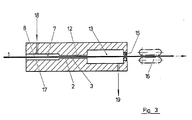
- Fig. 2 shows a preferred embodiment for performing the method according to the invention with the high pressure chamber (13), the sealing gap (12) and the die (15) and the trigger (16) that pulls the reinforcing fiber structure (1) through the entire unit .
- This structure (1) first passes through a space (10) completely filled with melt, which is under atmospheric pressure or slightly overpressure of maximum 0.5 bar.
- Line (11) provides for the ventilation and discharge of any excess polymer that may be used.
- the inlet nozzle (7/8) preferably consists of a cylindrical part (7) with little play between the sliver (1) and the wall and a conical part (8). If there is a slight overpressure in room (10), the nozzle is at least partially filled with polymer melt, so that the air surrounding the roving is squeezed out.
- the fiber sliver is then drawn through the gap (12) described in FIG. 1 into the high-pressure space (13). In (12/13) the actual impregnation of the fiber structure with the thermoplastic takes place. Then the molding nozzle (15) gives the profile its final external shape. As a rule, a slight excess of polymer which can be recycled is used to control the concentration of dissolved air in the high-pressure chamber (13).
- the amount of polymer generally added with the aid of an extruder or a pump, for example a gear pump, preferably through line (14), is less than five times, preferably twice the amount of polymer discharged with the finished composite material. The excess is passed through the sealing gap (12) and discharged through the overflow (11), where the slight excess pressure in the space (10) is set by throttling.
- the wall distance of the belt in the high-pressure chamber (13) can be dimensioned such that no further significant increase in pressure occurs in the direction of withdrawal. If short polymer dwell times are desired for sensitive polymers, it is advisable to guide the reinforcing fiber tape close to the wall. This can result in a further calculable pressure increase along the high-pressure space. In the limit case, the sealing gap (12) and the high-pressure chamber (13) can have the same gap width. Then the pressure between the space (10) and the molding nozzle (15) increases linearly (assuming isothermal behavior).
- the shape of the cross-sectional area of the sealing gap (12) depends on the geometry of the product. It is preferably designed so that a uniform sealing gap is created between the reinforcing fiber structure and the wall. However, asymmetries between the fiber sliver and the gap can also be advantageous, for example if fiber breakage, dirt particles etc. to be discharged with the leakage current (6) through line (11). Special channels on one side or on both sides of the belt are also conceivable for this purpose. In the case of narrow strips, for example, the use of a cylindrical bore can be advantageous.
- thermoplastic melt is added at point (18) and guided in direct current with the belt.
- the inlet channel (17) can have the same gap width as the sealing gap (12). But it can also be made wider.
- the channel (17) can also be corrugated or contain internals, for example in the form of cylinders or cylinder cutouts. Since the reinforcing fiber structure (1) already runs in the width that corresponds to the product, these internals do not have a wide-ranging effect.
- thermoplastic melt is metered by precisely working metering devices, for example spinning pumps, so that the excess amounts remain small.
- Excesses are preferably removed through the inlet nozzle (7/8), but can also be removed from the high-pressure chamber on the way (19) with the aid of a pressure relief valve.
- the melting task through the schematically indicated lines (14) or (18) can be designed such that the melt is added rotationally symmetrically on the circumference.
- a preferred embodiment is a nozzle fed by an extruder, through which the sliver passes either centrally or - for example when using rovings - in an annular gap on the circumference.
- the entire devices according to FIGS. 2 and 3 are kept at the desired processing temperature by heating.
- a division is preferred in at least four independent heating zones, which include the inlet nozzle (7/8) and the space (10) as well as the gap (12) and the high-pressure space (13) and the shaping nozzle (15).
- the temperature at which the sealing gap (12) is held is of particular importance for the method.
- the aim will be to keep the temperature in the high-pressure chamber (13) as high as possible, so that the viscosity for impregnating the reinforcing fiber structure remains as low as possible.
- the pressure difference generated along the sealing gap is proportional to the viscosity of the thermoplastic, a temperature that is as close as possible to the melting temperature of the thermoplastic is advantageous.
- a low nozzle outlet temperature which is preferably below the melting temperature of the thermoplastic, makes it possible to set a well-shaped strand under conditions which are gentle on the fibers.
- the strand can be post-treated, for example, by cooling with a temperature program or by smoothing with a rolling mill.
- Such a reduction in viscosity depending on the shear rate is a fundamental property of molten polymers.
- the process is particularly advantageous if the impregnation is carried out with polymers which have a strong dependence of the viscosity on the shear rate, for example liquid-crystal polymers or acrylonitrile-butadiene-styrene polymers (ABS).
- the rovings (1) are preferably placed in a flat, wide band before entering the inlet nozzle (8/9), which makes impregnation easier.
- the roving is preferably pretreated to separate the filaments, for example by mechanically breaking the size, thermal treatment or ultrasound.
- preheating before entry into the inlet nozzle (8/9) has proven to be advantageous.
- a defined fabric tension must be specified before entering the inlet nozzle, which when using rovings, preferably when laying the flat, wide band mentioned, when Use of textiles, for example directly when pulling off the supply rolls, can take place.
- the width of the band running into the sealing gap (8/9) can exceed the width of the shaping nozzle (15) or match the width of the nozzle.
- impregnation aids on which the reinforcing fiber structure slides over a polymer film that forms, can be advantageous, particularly in the case of highly viscous thermoplastics.
- Such impregnation aids which consist for example in whole or in part of cylinders with a circular or elliptical base, have no function for keeping the tape wide and are only required at viscosities above 30 Pas where other impregnation devices fail for the reasons mentioned.
- the flow profile and pressure build-up in sealing gap 3 can be calculated using various simplifying assumptions (e.g. Newtonian flow, frictionless).
- a composite profile is produced by impregnating a glass fiber roving 2400 tex (filament diameter 10 ⁇ m) with polyamide 6 (Bayer ®Durethan B 30 S).
- the glass fiber ribbon has a thickness of approx. 120 ⁇ m, so that the distance between the fiber strip and the wall is approx. 0.44 mm.
- the gap area is cooled to a temperature of approx. 240 ° C, while the actual high-pressure impregnation section remains at 290 ° C.
- a composite flat profile is produced by pulling a carbon fiber tape with 24,000 fibers with a filament diameter of 7 ⁇ m corresponding to 1600 tex through a melt of polyphenylene sulfide (Bayer ®Tedur).
- the species used has a melt viscosity of 25 Pas at the impregnation temperature of 320 ° C.
- the distance between the carbon fiber tape and the wall is approximately 0.19 mm.
- a composite flat profile is produced by pulling a carbon fiber tape (C-fiber from Example 5) through a melt of thermotropic liquid crystal polymer (Bayer test product KU 1 - 9231).
- the gap length is 100 mm
- the return flow rate V ⁇ 0.5 l / h.
Abstract
Description
Kontinuierliche Verfahren zur Herstellung von Verbundwerkstoffen wie endlosen Profilen, Bändern und flächigen Gebilden, bei denen endlose Fasern, beispielsweise Glasfaser-, Kohlenstoffaser- oder Aramidfaser-Rovings durch eine Schmelze eines thermoplastischen Kunststoffs gezogen werden, sind bekannt.Continuous processes for the production of composite materials such as endless profiles, strips and flat structures, in which continuous fibers, for example glass fiber, carbon fiber or aramid fiber rovings, are drawn through a melt of a thermoplastic, are known.
So wird in der EP-A 0 056 703 ein Verfahren beschrieben, bei dem Verstärkungsfaser-Rovings durch eine Schmelze eines thermoplastischen Kunststoffs gezogen werden, in die mindestens eine beheizte Oberfläche zum Spreizen des Rovings eintaucht. Die so hergestellten Werkstoffe sollen Longitudinal-Biegemoduln von mindestens 70 %, bevorzugt mindestens 90 % des theoretischen Wertes besitzen.For example, EP-A 0 056 703 describes a method in which reinforcing fiber rovings are drawn through a melt of a thermoplastic material into which at least one heated surface is immersed for spreading the roving. The materials produced in this way should have longitudinal bending modules of at least 70%, preferably at least 90% of the theoretical value.
Praktisch sind immer mehrere Spreizvorrichtungen erforderlich. Die aufzubringenden Abzugskräfte steigen aber mit der Zahl der Spreizvorrichtungen (bei zylindrischen Spreizvorrichtungen mit steigenden Gesamtumschlingungswinkel), mit der Viskosität der Schmelze und mit der Abzugsgeschwindigkeit stark an. Da große Abzugskräfte die Verstärkungsfaser schädigen und damit die Eigenschaften des Verbundwerkstoffs verschlechern, ist das zur Verfügung stehende "Arbeitsfenster" sehr klein. Es kommt hinzu, daß die Imprägniergüte und damit auch die Qualität der Produkte (im Biegeversuch) mit steigender Viskosität der Schmelze und steigender Abzugsgeschwindigkeit abnehmen. Daher führt das Verfahren der EP-A 0 056 703 nur bei Viskositäten der Schmelze bis zu 30 Pas und bei niedrigen Abzugsgeschwindigkeiten (unter 0,3 m/min) zu guten Ergebnissen. Somit sind bei den meisten thermoplastischen Kunststoffen gerade die interessanten hochmolekularen und damit hochviskosen Typen ganz ausgeschlossen und im übrigen nur ![]()
![]()
Rotierende Oberflächen zum Spreizen der Rovings verringern zwar Abzugskräfte, aber gebrochene Fasern, die in der Regel in den zugeführten Rovings enthalten sind, haften an den rotierenden Teilen und bauen sich dort auf, so daß der Imprägnierprozeß nach kurzer Zeit zum Erliegen kommt.Rotating surfaces for spreading the rovings reduce pulling forces, but broken fibers, which are usually contained in the supplied rovings, adhere to the rotating parts and build up there, so that the impregnation process comes to a standstill after a short time.
Die genannten Schwierigkeiten lassen sich auch nicht durch ein weiteres, ebenfalls bekanntes Verfahren vermeiden, bei dem der geschmolzene Thermoplast direkt in einen Spalt zwischen Verstärkungsfaser-Roving und Spreizeroberfläche gegeben wird.The difficulties mentioned cannot be avoided by another, also known method, in which the melted thermoplastic is placed directly into a gap between the reinforcing fiber roving and the spreader surface.
Außerdem sind Verfahren bekannt, die mit Querspritzköpfen arbeiten, wie sie prinzipiell schon lange bei der Kabelummantelung verwendet werden. Dabei wird thermoplastisches Material aus einem Schmelzextruder auf einen Verstärkungsfaserstrang aufgebracht, der sich in der Regel senkrecht zur Fließrichtung der Schmelze bewegt. Solche Verfahren mit teilweise speziell modifizierten Werkzeugen werden in den US-PS 3 993 726, US-PS 4 588 538, EP 0 035 974 und EP 0 117 098 beschrieben.In addition, methods are known which work with crossheads, such as those which have long been used in principle Cable sheathing can be used. Thermoplastic material is applied from a melt extruder to a reinforcing fiber strand, which generally moves perpendicular to the direction of flow of the melt. Such methods with partially specially modified tools are described in US Pat. No. 3,993,726, US Pat. No. 4,588,538, EP 0 035 974 and EP 0 117 098.
In solchen Querspritzköpfen tritt aufgrund des Förderdruckes des Extruders in der Regel am Verstärkungsfaserstrang auf einer kurzen Strecke ein erhöhter Druck auf, der demnach nur kurzzeitig auf den Verstärkungsfaserstrang wirkt. Im Stand der Technik wird daher die Bedeutung des Druckes unterschiedlich bewertet: Während US-PS 3 993 726 von erforderlichem "hohem Druck" spricht, gebraucht US-PS 4 588 538 nur die Bezeichnung "unter Druck", EP-A 0 035 974 erwähnt dagegen eine fördernde Wirkung des Druckes im Querspritzkopf überhaupt nicht.In such crossheads, due to the delivery pressure of the extruder, an increased pressure generally occurs on the reinforcing fiber strand over a short distance, which therefore only has a brief effect on the reinforcing fiber strand. The meaning of the pressure is therefore evaluated differently in the prior art: While US Pat. No. 3,993,726 speaks of the required "high pressure", US Pat. No. 4,588,538 only uses the term "under pressure", EP-A 0 035 974 mentioned on the other hand, no promotional effect of the pressure in the crosshead.
Es wurde gefunden, daß sich endlose, hochfeste Profile, Bänder und dünne, flächige Gebilde aus Verbundwerkstoffen mit einem thermoplastischen Kunststoff als Matrix und endlosen Verstärkungsfasern herstellen lassen, wenn man die Verstärkungsfasern bei erhöhtem Druck auf größerer, definierter Länge durch eine Schmelze des thermoplastischen Kunststoffs führt. Bei dieser Arbeitsweise ist es nicht erforderlich, die Fasern im Bad aufzusprei zen. Spreizvorrichtungen und entsprechende Einbauten sind daher nicht erforderlich.It has been found that endless, high-strength profiles, strips and thin, flat structures made of composite materials with a thermoplastic as a matrix and endless reinforcing fibers can be produced if the reinforcing fibers are passed through a melt of the thermoplastic at a greater pressure and at a greater, defined length . With this procedure, it is not necessary to spread the fibers in the bath Zen. Spreading devices and corresponding internals are therefore not required.
Gegenstand der Erfindung ist somit ein Verfahren zur Herstellung von endlosen Formkörpern aus mit thermoplastischen Kunststoffen imprägnierten Gebilden aus Verstärkungsfasern, das dadurch gekennzeichnet ist, daß man ein Gebilde aus Verstärkungsfasern auf einer Länge von mindestens 300 mm unter einem Druck von 1 bis 800 bar durch eine Schmelze des thermoplastischen Kunststoffs führt.The invention thus relates to a process for the production of endless molded articles made of reinforcing fiber-impregnated structures, which is characterized in that a structure made of reinforcing fibers has a length of at least 300 mm under a pressure of 1 to 800 bar by means of a melt of the thermoplastic leads.
Bei diesem Verfahren bleiben die Abzugskräfte niedrig, so daß die Verstärkungsfasern schonend behandelt werden. Hohe Abzugsgeschwindigkeiten werden erreicht. Wegen des Fehlens von Einbauten kann das Imprägnierbad sehr lang sein, so daß auch bei hohen Abzugsgeschwindigkeiten ausreichende Verweilzeit und damit ausreichende Imprägniergüte und gute mechanische Eigenschaften erreicht werden. Der im Imprägnierbad herrschende Überdruck von 1 bis 800 bar, bevorzugt 10 bis 200 bar, auf einer Länge von mindestens 300 mm gewährleistet eine allseitige faserschonende Imprägnierung.With this method, the pulling forces remain low, so that the reinforcing fibers are treated gently. High take-off speeds are achieved. Due to the lack of internals, the impregnation bath can be very long, so that sufficient residence time and thus sufficient impregnation quality and good mechanical properties can be achieved even at high take-off speeds. The overpressure of 1 to 800 bar, preferably 10 to 200 bar, prevailing in the impregnation bath over a length of at least 300 mm ensures that the impregnation is gentle on all sides.
Die anzuwendenden Bedingungen hinsichtlich Druck und Länge hängen von Titer und Aufbau des zu imprägnierenden Verstärkungsfasergebildes ab, das im folgenden näher spezifiziert wird. Es ist sofort einleuchtend, daß ein dünner, ungedrehter Faserroving bei niedrigerem Druck und/oder kürzerer Länge der Druckzone imprägniert werden kann als beispielsweise ein schweres Verstärkungsfaser-Gewebe.The conditions to be used with regard to pressure and length depend on the titer and structure of the reinforcing fiber structure to be impregnated, which is specified in more detail below. It is immediately clear that a thin, untwisted fiber roving can be impregnated at a lower pressure and / or a shorter length of the pressure zone than, for example, a heavy reinforcing fiber fabric.
Erfindungsgemäß kann man auch thermoplastische Kunststoffe mit hohen Schmelzviskositäten verarbeiten. Damit kann man prinzipiell alle thermoplastischen Kunststoffe verwenden. Bevorzugt sind jedoch solche mit Schmelzviskositäten bei Verarbeitungstemperatur unter 500 Pas, besonders solche mit Schmelzviskositäten unter 200 Pas.According to the invention, thermoplastics with high melt viscosities can also be processed. In principle, you can use all thermoplastics. However, those with melt viscosities at processing temperature below 500 Pas are preferred, especially those with melt viscosities below 200 Pas.
Wesentlich ist, daß der Thermoplast ein niedrigeres Erweichungsintervall bzw. Schmelzpunkt besitzt als das Material, aus dem die Verstärkungsfasern bestehen. In Frage kommen beispielsweise Thermoplaste im weitesten Sinne, d.h. Stoffe, die sich reversibel oder intermediär thermoplastisch verhalten, z.B. thermoplastische Kunststoffe und thermoplastische Phasen von Duromeren. Beispiele für Thermoplaste sind Polyolefine, Vinylpolymerisate wie Polyvinylhalogenide, Polyvinylester, Polyvinylether, Polyacrylate, Polymethacrylate und organische Celluloseester, sowie Polyamide, Polyurethane, Polyharnstoffe, Polyimide, Polyester, Polyether, Polystyrole, Polyhydantoine, Polyphenylenoxide, Polyphenylensulfide, Polysulfone, Polycarbonate, Phenolharzvorläufer, Furanharzvorläufer, Melaminharzvorläufer, Epoxiharzvorläufer, Verbindungen mit polymerisations- und/oder polyadditionsfähigen Doppelbindungen, Polyimidvorläufer, Polyetherketone, Polyetheretherketone, Polyethersulfone, Polyetherimide, Polyamidimide, Polyfluoralkene, Polyestercarbonate und Liquid-crystal-Polymere; ferner unpolare thermoplastische Polymere (z.B. Polyolefine), denen polare Gruppen aufgepfropft wurden.It is essential that the thermoplastic has a lower softening interval or melting point than the material from which the reinforcing fibers are made. For example, thermoplastics in the broadest sense come into question, ie substances which behave reversibly or intermediately thermoplastic, for example thermoplastic plastics and thermoplastic phases of thermosets. Examples of thermoplastics are polyolefins, vinyl polymers, such as polyvinyl halides, polyvinyl esters, polyvinyl ethers, polyacrylates, polymethacrylates and organic cellulose esters, as well as polyamides, polyurethanes, polyureas, polyimides, polyesters, polyethers, polystyrenes, polyhydantoins, polyphenylene oxides, polyphenylene sulfides, phenol precursors, polycarbonate resins, poly-sulfonate precursors, Melamine resin precursors, epoxy resin precursors, compounds with double bonds capable of polymerization and / or polyaddition, polyimide precursors, polyether ketones, polyether ether ketones, polyether sulfones, polyetherimides, polyamideimides, polyfluoroalkenes, polyester carbonates and liquid crystal polymers; also non-polar thermoplastic polymers (eg polyolefins), to which polar groups have been grafted.
Bevorzugte Thermoplaste sind Polyethylene, Polypropylene, Polybutylene, Polypentene, Polyvinylchloride, Polymethylmethacrylate, Polyacrylnitrile, Polymethacrylnitrile, Polystyrol enthaltende Mehrphasenkunststoffe wie ABS, Polyamide des Typs 6, Polyamide des Typs 6-6, Polyurethane, Polyethylenterephthalate, Polybutylenterephthalate, Bisphenol-A-Polycarbonate, Polyphenylensulfide, Polyetherketone, Polyetheretherketone, Polyethersulfone, Polysulfone, Polyetherimide, Polyamidimide, Polyestercarbonate, Liquid-crystal-Polymere und Polypropylen, dem polare Gruppen aufgepfropft wurden.Preferred thermoplastics are polyethylenes, polypropylenes, polybutylenes, polypentenes, polyvinyl chlorides, polymethyl methacrylates, polyacrylonitriles, polymethacrylonitriles, polystyrene-containing multiphase plastics such as ABS, polyamides of
Die Thermoplaste können auch in den verschiedensten Kombinationen vorliegen, z.B. als Copolymere, Blockpolymere, Pfropfpolymere, Mischpolymere und Polymergemische.The thermoplastics can also be in various combinations, e.g. as copolymers, block polymers, graft polymers, mixed polymers and polymer mixtures.
Der chemische Aufbau der Verstärkungsfasern und des Thermoplasts kann auch gleichartig sein, z.B. können beide aus Polyester bestehen. Wesentlich ist aber auch in diesem Fall, daß das Material, aus dem die Verstärkungsfasern bestehen ein höheres Erweichungsintervall bzw. Schmelzpunkt hat als das Material, aus dem die Thermoplastmatrix besteht.The chemical structure of the reinforcing fibers and the thermoplastic can also be of the same type, e.g. can both be made of polyester. It is also essential in this case that the material from which the reinforcing fibers are made has a higher softening interval or melting point than the material from which the thermoplastic matrix is made.
Nach dem Verfahren können auch Harzsysteme verarbeitet werden, die nach der Imprägnierung in einem weiteren Schritt einer Vernetzung unterzogen werden, wie Duroplast- oder Elastomersysteme. Die Anwendung von Druck ist hier vorteilhaft, weil eine bessere Imprägnierung bzw. höhere Produktionsgeschwindigkeiten und längere Topfzeiten erreicht werden, weil eine Verarbeitung bei höheren Viskositäten möglich ist. Das Wort "Thermoplast" ist dann im Text sinngemäß durch das Wort "härtbare Harzsysteme" zu ersetzen.The process can also be used to process resin systems which, after impregnation, are subjected to crosslinking in a further step, such as thermoset or elastomer systems. The use of pressure is advantageous here because of better impregnation or higher production speeds and longer pot lives because processing with higher viscosities is possible. The word "thermoplastic" is then to be replaced in the text by the word "curable resin systems".
Erfindungsgemäß können auch sehr spröde Fasern, z.B. Hochmodulcarbonfasern, eingesetzt werden, weil durch das Fehlen von Einbauten die Fasern nicht gebogen und umgelenkt werden müssen.According to the invention, very brittle fibers, e.g. High modulus carbon fibers are used because the lack of internals means that the fibers do not have to be bent and deflected.
Der chemische Aufbau der Verstärkungsfasern kann von der unterschiedlichsten Art sein. Wesentlich ist nur, daß die Verstärkungsfasern einen höheren Erweichungs- bzw. Schmelzpunkt besitzen, als die jeweils vorliegende Thermoplastmatrix. Beispiele für Fasermaterialien sind anorganische Materialien wie silikatische und nichtsilikatische Gläser der verschiedensten Art, Kohlenstoff, Bor, Siliciumcarbid, Metalle, Metallegierungen, Metalloxide, Metallnitride, Metallcarbide und Silikate, sowie organische Materialien wie natürliche und synthetische Polymere, beispielsweise Polyacrylnitrile, Polyester, ultrahochgereckte Polyolefinfasern, Polyamide, Polyimide, Aramide, Liquid-crystal-Polymere, Polyphenylensulfide, Polyetherketone, Polyetheretherketone, Polyetherimide, Baumwolle und Cellulose. Bevorzugt sind hochschmelzende Materialien, beispielsweise Gläser, Kohlenstoff, Aramide, Liquid-crystal-Polymere, Polyphenylensulfide, Polyetherketone, Polyetheretherketone und Polyetherimide.The chemical structure of the reinforcing fibers can be of the most varied of types. It is only essential that the reinforcing fibers have a higher softening or melting point than the respective thermoplastic matrix. Examples of fiber materials are inorganic materials such as silicate and non-silicate glasses of the most varied types, carbon, boron, silicon carbide, metals, metal alloys, metal oxides, metal nitrides, metal carbides and silicates, and organic materials such as natural and synthetic polymers, for example polyacrylonitriles, polyesters, ultra-high-stretch polyolefin fibers, Polyamides, polyimides, aramids, liquid crystal polymers, polyphenylene sulfides, polyether ketones, polyether ether ketones, polyether imides, cotton and cellulose. High-melting materials, for example glasses, carbon, aramids, liquid crystal polymers, polyphenylene sulfides, polyether ketones, polyether ether ketones and polyether imides, are preferred.
Die Verstärkungsfasern können in dem erfindungsgemäßen Leichtverbundwerkstoff gleichmäßig verteilt sein, sie können jedoch auch in bestimmten Teilen des Werkstoffs, z.B. in den Randbereichen und/oder besonderen Verstärkungszonen, in einem größeren Anteil vorhanden sein als in anderen Teilen des Werkstoffes.The reinforcing fibers can be evenly distributed in the lightweight composite material according to the invention, but they can also be in certain parts of the material, e.g. be present in the edge areas and / or special reinforcement zones in a larger proportion than in other parts of the material.
Erfindungsgemäß können außer Rovings der Verstärkungsfasern auch andere lineare Formkörper wie Fasern, Garne, Zwirne, Seile und textile Gebilde, wie Gewebe, Gewirke, Gestricke, Geflechte, zu Verbundwerkstoffen mit guten mechanischen Eigenschaften verarbeitet werden.According to the invention, in addition to rovings of the reinforcing fibers, other linear moldings such as fibers, yarns, twists, ropes and textile structures, such as woven fabrics, knitted fabrics, knitted fabrics, braids, can be processed to composite materials with good mechanical properties.
Durch die erfindungsgemäß niedrigen Abzugskräfte wird die Verarbeitung von textilen Gebilden möglich, die in Zugrichtung dehnfähig sind, beispielsweise Gewirke, Gestricke und Geflechte.The low pull-off forces according to the invention make it possible to process textile structures which are stretchable in the pulling direction, for example knitted fabrics, knitted fabrics and braids.
Der Gehalt an Verstärkungsfasern im fertigen Erzeugnis ist allgemein 20 bis 85 Vol-%, bevorzugt 40 - 70 Vol-%, bei Profilen mit rein unidirektionaler Verstärkung bei 30 bis 90 Vol%, bevorzugt 40 - 80 Vol %.The content of reinforcing fibers in the finished product is generally 20 to 85 vol%, preferably 40-70 vol%, for profiles with purely unidirectional reinforcement 30 to 90 vol%, preferably 40-80 vol%.
Ein weiterer Vorteil des erfindungsgemäßen Verfahrens liegt in der Möglichkeit einer faserschonenden Ausformung des Profils in der Formdüse. Die Düse kann nämlich so gestaltet werden, daß sie den Druckraum direkt nach außen abschließt, so daß die Druckdifferenz zwischen dem Schmelzebad und der Umgebung längs der Düsenlänge abgebaut wird. Dadurch wird schmelzflüssiges Polymeres zwischen die Oberfläche des Bandes und die Düse gedrückt und somit Oberflächenreibung der Verstärkungsfaserfilamente an der Düse vermieden oder zumindest stark reduziert.Another advantage of the method according to the invention lies in the possibility of a gentle shaping of the profile in the molding nozzle. The nozzle can namely be designed so that it closes the pressure chamber directly to the outside, so that the pressure difference between the melt bath and the environment is reduced along the length of the nozzle. This will make molten polymer pressed between the surface of the belt and the nozzle, thus avoiding or at least greatly reducing surface friction of the reinforcing fiber filaments on the nozzle.
Die geometrische Form und die Abmessungen der Düse können in weiten Grenzen variiert werden, so daß Verbundwerkstoffprofile oder -bänder mit verschiedenen Formen und Abmessungen hergestellt werden können. Bevorzugt sind Rundprofile mit Durchmessern bis 30 mm, bevorzugt 18 mm, und Rechteckprofile mit Breiten bis zu 2500 mm und mit Dicken bis zu 10 mm. Besonders bevorzugt sind dünne Bänder mit Dicken bis zu 1 mm.The geometric shape and dimensions of the nozzle can be varied within wide limits, so that composite profiles or strips with different shapes and dimensions can be produced. Round profiles with diameters up to 30 mm, preferably 18 mm, and rectangular profiles with widths up to 2500 mm and with thicknesses up to 10 mm are preferred. Thin strips with thicknesses of up to 1 mm are particularly preferred.
Das Verstärkungsfasergebilde kann auf verschiedene Weise in den Schmelzeraum eingeführt werden. Beispielsweise kann es durch eine Düse mit engem Spiel eingezogen werden. Bevorzugt wird das Fasergebilde durch einen Spalt ohne Wandberührung in den Schmelzeraum eingeführt. Die Druckdifferenz wird dabei durch die Konvektionsströmung oder Schleppströmung, die durch die Haftung des Polymeren auf dem sich bewegenden Band entsteht, überwunden.The reinforcing fiber structure can be introduced into the melting space in various ways. For example, it can be drawn in through a nozzle with tight play. The fiber structure is preferably introduced into the melting space through a gap without contacting the wall. The pressure difference is overcome by the convection flow or drag flow, which is caused by the adhesion of the polymer to the moving belt.
Fig. 1 zeigt einen solchen Spalt (3) zwischen dem sich bewegenden Band (1) und der festen Wand (2). Durch die Haftung hat das Polymere an der Oberfläche des Bandes (1) dieselbe Geschwindigkeit wie das Band selbst. Dabei entsteht in Bandnähe eine Konvektionsströmung oder Schleppströmung in Bandrichtung (5) und in Wandnähe aufgrund der Kontinuitätsgleichung eine Strömung in Gegen richtung (Leckströmung) (6). Wenn im Hochdruckraum weder Polymeres zugeführt noch abgeführt wird, müssen die in beiden Richtungen strömenden Mengen genau gleich sein.Fig. 1 shows such a gap (3) between the moving belt (1) and the fixed wall (2). Due to the adhesion, the polymer on the surface of the belt (1) has the same speed as the belt itself. A convection flow or drag flow in the belt direction (5) arises in the vicinity of the belt and a flow in the opposite direction near the wall due to the continuity equation direction (leakage flow) (6). If no polymer is added or removed in the high-pressure chamber, the amounts flowing in both directions must be exactly the same.
Die Abtrennung von Hoch- und Niederdruckraum ist keine Dichtung im eigentlichen Sinn. Die Strömung im Spalt bestimmt vielmehr den Druck im eigentlichen Hochdruckraum. Die sich einstellende Druckdifferenz hängt von den geometrischen Abmessungen (Spaltbreite, Banddicke, Spaltlänge) sowie von der Viskosität des Mediums, der Bandgeschwindigkeit und einem evtl. überlagertem Gesamtmengenstrom ab. Ein Computerprogramm, das auf die entsprechenden Gleichungen der laminaren Strömung aufbaut, gestattet die Berechnung der jeweiligen Druckdifferenz.The separation of high and low pressure space is not really a seal. The flow in the gap rather determines the pressure in the actual high-pressure space. The pressure difference that arises depends on the geometrical dimensions (gap width, strip thickness, gap length) as well as on the viscosity of the medium, the strip speed and a possibly superimposed total flow. A computer program, which builds on the corresponding equations of the laminar flow, allows the calculation of the respective pressure difference.
Ein besonderer Vorteil der Anordnung ist ein Ansteigen des Druckes und damit der Imprägniergüte mit steigender Bandgeschwindigkeit und steigender Viskosiät, d.h. für die Fälle, in denen die Imprägnierung schwieriger wird. Ein freier Parameter zur Einstellung des Druckes ist eine Überschuß-Polymermenge, die beispielsweise mit einem Extruder oder einer Pumpe in den Hochdruckraum eingeleitet wird und die durch den Spalt (3) in Gegenrichtung (6) strömt.A particular advantage of the arrangement is an increase in the pressure and thus the impregnation quality with increasing belt speed and increasing viscosity, i.e. in cases where impregnation becomes more difficult. A free parameter for setting the pressure is an excess amount of polymer which is introduced into the high-pressure chamber, for example with an extruder or a pump, and which flows through the gap (3) in the opposite direction (6).
Fig. 2 zeigt eine bevorzugte Ausführungsform zur Durchführung des erfindungsgemäßen Verfahrens mit dem Hochdruckraum (13), dem Dichtungsspalt (12) und der Formdüse (15) und dem Abzug (16), der das Verstärkungsfaser-Gebilde (1) durch die gesamte Einheit zieht. Dieses Gebilde (1) durchläuft zunächst einen vollständig mit Schmelze gefüllten Raum (10), der unter Atmosphärendruck oder leichtem Überdruck von maximal 0,5 bar steht. Leitung (11) sorgt für die Entlüftung und Ableitung einer möglicherweise eingesetzten Überschuß-Polymermenge. Die Einlaufdüse (7/8) besteht bevorzugt aus einem zylindrischen Teil (7) mit geringem Spiel zwischen Faserband (1) und Wand und einem konischen Teil (8). Bei leichtem Überdruck in Raum (10) wird die Düse zumindest teilweise mit Polymerschmelze gefüllt, so daß die den Roving umgebende Luft abgequetscht wird.Fig. 2 shows a preferred embodiment for performing the method according to the invention with the high pressure chamber (13), the sealing gap (12) and the die (15) and the trigger (16) that pulls the reinforcing fiber structure (1) through the entire unit . This structure (1) first passes through a space (10) completely filled with melt, which is under atmospheric pressure or slightly overpressure of maximum 0.5 bar. Line (11) provides for the ventilation and discharge of any excess polymer that may be used. The inlet nozzle (7/8) preferably consists of a cylindrical part (7) with little play between the sliver (1) and the wall and a conical part (8). If there is a slight overpressure in room (10), the nozzle is at least partially filled with polymer melt, so that the air surrounding the roving is squeezed out.
In Fig. 2 ist zusätzlich das Druckprofil längs der beschriebenen technischen Einrichtung schematisch angedeutet.In Fig. 2, the pressure profile along the technical device described is also indicated schematically.
Danach wird das Faserband durch den in Fig. 1 beschriebenen Spalt (12) in den Hochdruckraum (13) gezogen. In (12/13) erfolgt die eigentliche Imprägnierung des Fasergebildes mit dem Thermoplasten. Anschließend gibt die Formdüse (15) dem Profil seine endgültige äußere Gestalt. In der Regel wird mit einem leichten rezirkulierbaren Polymerüberschuß gearbeitet, um die Konzentration an gelöster Luft im Hochdruckraum (13) zu kontrollieren. Die in der Regel mit Hilfe eines Extruders oder einer Pumpe, beispielsweise einer Zahnradpumpe, bevorzugt durch Leitung (14) zugegebenen Polymermengen liegen bei weniger als dem fünffachen, bevorzugt zweifachen der mit dem fertigen Verbundwerkstoff ausgetragenen Polymermenge. Der Überschuß wird durch den Dichtungsspalt (12) geleitet und durch den Überlauf (11) ausgetragen, wo durch Drosselung der leichte Überdruck im Raum (10) eingestellt wird.The fiber sliver is then drawn through the gap (12) described in FIG. 1 into the high-pressure space (13). In (12/13) the actual impregnation of the fiber structure with the thermoplastic takes place. Then the molding nozzle (15) gives the profile its final external shape. As a rule, a slight excess of polymer which can be recycled is used to control the concentration of dissolved air in the high-pressure chamber (13). The amount of polymer generally added with the aid of an extruder or a pump, for example a gear pump, preferably through line (14), is less than five times, preferably twice the amount of polymer discharged with the finished composite material. The excess is passed through the sealing gap (12) and discharged through the overflow (11), where the slight excess pressure in the space (10) is set by throttling.
Der Wandabstand des Bandes im Hochdruckraum (13) kann so bemessen werden, daß in Abzugsrichtung keine weitere nennenswerte Druckerhöhung auftritt. Wenn bei empf indlichen Polymeren geringe Polymer-Verweilzeiten angestrebt werden, empfiehlt sich jedoch eine wandnahe Führung des Verstärkungsfaserbandes. Dadurch kann eine weitere kalkulierbare Druckerhöhung längs des Hochdruckraumes auftreten. Im Grenzfall können Dichtungsspalt (12) und Hochdruckraum (13) die gleiche Spaltweite aufweisen. Dann steigt der Druck zwischen dem Raum (10) und der Formdüse (15) linear an (isothermes Verhalten vorausgesetzt).The wall distance of the belt in the high-pressure chamber (13) can be dimensioned such that no further significant increase in pressure occurs in the direction of withdrawal. If short polymer dwell times are desired for sensitive polymers, it is advisable to guide the reinforcing fiber tape close to the wall. This can result in a further calculable pressure increase along the high-pressure space. In the limit case, the sealing gap (12) and the high-pressure chamber (13) can have the same gap width. Then the pressure between the space (10) and the molding nozzle (15) increases linearly (assuming isothermal behavior).
Die Form der Querschnittsfläche des Dichtungsspaltes (12) richtet sich nach der Geometrie des Erzeugnisses. Sie wird bevorzugt so gestaltet, daß ein gleichmäßiger Dichtspalt zwischen dem Verstärkungsfaser-Gebilde und der Wand entsteht. Allerdings können auch Asymmetrien zwischen Faserband und Spalt vorteilhaft sein, beispielsweise, wenn Faserbruch, Schmutzpartikel u.ä. mit dem Leckstrom (6) durch Leitung (11) ausgetragen werden soll. Dazu sind auch spezielle Kanäle auf einer Seite oder beiden Seiten des Bandes denkbar. Bei schmalen Bändern kann beispielsweise die Verwendung einer zylindrischen Bohrung vorteilhaft sein.The shape of the cross-sectional area of the sealing gap (12) depends on the geometry of the product. It is preferably designed so that a uniform sealing gap is created between the reinforcing fiber structure and the wall. However, asymmetries between the fiber sliver and the gap can also be advantageous, for example if fiber breakage, dirt particles etc. to be discharged with the leakage current (6) through line (11). Special channels on one side or on both sides of the belt are also conceivable for this purpose. In the case of narrow strips, for example, the use of a cylindrical bore can be advantageous.
Fig. 3 zeigt eine weitere bevorzugte Vorrichtung zur Durchführung des erfindungsgemäßen Verfahrens. Hier wird die Thermoplastschmelze an der Stelle (18) zugegeben und im Gleichstrom mit dem Band geführt. Der Einlaufkanal (17) kann dabei die gleiche Spaltweite wie der Dichtspalt (12) haben. Er kann aber auch breiter ausgebildet sein. Um eine Vorverteilung der Schmelze im Verstärkungsfaser-Gebilde zu erhalten, kann der Kanal (17) auch gewellt sein oder Einbauten, beispielsweise in Form von Zylindern oder Zylinderausschnitten enthalten. Da das Verstärkungsfaser-Gebilde (1) bereits in der Breite einläuft, die dem Erzeugnis entspricht, haben diese Einbauten keine breithaltende Wirkung.3 shows a further preferred device for carrying out the method according to the invention. Here the thermoplastic melt is added at point (18) and guided in direct current with the belt. The inlet channel (17) can have the same gap width as the sealing gap (12). But it can also be made wider. In order to obtain a pre-distribution of the melt in the reinforcing fiber structure, the channel (17) can also be corrugated or contain internals, for example in the form of cylinders or cylinder cutouts. Since the reinforcing fiber structure (1) already runs in the width that corresponds to the product, these internals do not have a wide-ranging effect.
Die Thermoplastschmelze wird durch genau arbeitende Dosierorgane, beispielsweise Spinnpumpen, so dosiert zugeführt, daß die Überschußmengen klein bleiben. Überschüsse werden bevorzugt durch die Einlaufdüse (7/8) entfernt, können aber auch mit Hilfe eines Überdruckventils auf dem Weg (19) aus dem Hochdruckraum entnommen werden.The thermoplastic melt is metered by precisely working metering devices, for example spinning pumps, so that the excess amounts remain small. Excesses are preferably removed through the inlet nozzle (7/8), but can also be removed from the high-pressure chamber on the way (19) with the aid of a pressure relief valve.
Die Schmelzeaufgabe durch die schematisch angedeuteten Leitungen (14) oder (18) kann konstruktiv so ausgeführt werden, daß die Schmelze rotationssymmetrisch am Umfang zugegeben wird. Bevorzugte Ausführungsform ist eine von einem Extruder gespeiste Düse, die vom Faserband entweder zentral oder - beispielsweise bei Verwendung von Rovings - in einem Ringspalt auf dem Umfang durchlaufen wird.The melting task through the schematically indicated lines (14) or (18) can be designed such that the melt is added rotationally symmetrically on the circumference. A preferred embodiment is a nozzle fed by an extruder, through which the sliver passes either centrally or - for example when using rovings - in an annular gap on the circumference.
Die gesamten Vorrichtungen nach Fig. 2 und Fig. 3 werden durch eine Beheizung auf der gewünschten Verarbeitungstemperatur gehalten. Bevorzugt ist dabei eine Aufteilung in mindestens vier unabhängige Beheizungszonen, die die Einlaufdüse (7/8) und den Raum (10) sowie den Spalt (12) sowie den Hochdruckraum (13) sowie die Formdüse (15) umfassen.The entire devices according to FIGS. 2 and 3 are kept at the desired processing temperature by heating. A division is preferred in at least four independent heating zones, which include the inlet nozzle (7/8) and the space (10) as well as the gap (12) and the high-pressure space (13) and the shaping nozzle (15).
Dabei ist insbesondere die Temperatur, auf der der Dichtungsspalt (12) gehalten wird von Bedeutung für das Verfahren. In der Regel wird man anstreben, die Temperatur im Hochdruckraum (13) möglichst hoch zu halten, so daß die Viskosität zur Imprägnierung des Verstärkungsfaser-Gebildes möglichst niedrig bleibt. Da die längs des Dichtungsspaltes erzeugte Druckdifferenz aber proportional zur Viskosität des Thermoplasten verläuft, ist hier eine Temperatur günstig, die möglichst nahe an der Schmelztemperatur des Thermoplasten liegt.The temperature at which the sealing gap (12) is held is of particular importance for the method. As a rule, the aim will be to keep the temperature in the high-pressure chamber (13) as high as possible, so that the viscosity for impregnating the reinforcing fiber structure remains as low as possible. However, since the pressure difference generated along the sealing gap is proportional to the viscosity of the thermoplastic, a temperature that is as close as possible to the melting temperature of the thermoplastic is advantageous.
Wichtig ist auch eine unabhängige Einstellmöglichkeit für die Temperatur der Formdüse (15), wobei zusätzlich in unterschiedliche Heizzonen unterteilt werden kann. Durch eine niedrige Düsenaustrittstemperatur, die bevorzugt unter der Schmelztemperatur des Thermoplasten liegt, ist die Einstellung eines gut geformten Stranges unter faserschonenden Bedingungen möglich. Nach dem Austritt aus der Formdüse kann der Strang beispielsweise durch Kühlen mit einem Temperaturprogramm oder durch Glätten mit einem Walzwerk nachbehandelt werden.It is also important to be able to set the temperature of the shaping nozzle (15) independently, it being also possible to divide it into different heating zones. A low nozzle outlet temperature, which is preferably below the melting temperature of the thermoplastic, makes it possible to set a well-shaped strand under conditions which are gentle on the fibers. After exiting the molding die, the strand can be post-treated, for example, by cooling with a temperature program or by smoothing with a rolling mill.
Eine andere wichtige Möglichkeit zur Reduzierung der Viskosität bei der Imprägnierung des Faser-Gebildes ist das Aufbringen hoher Schubspannungen im Dichtungsspalt 3, wodurch bei strukturviskosen Stoffen die Viskosität erniedrigt wird. Wie aus Fig. 1 ersichtlich, tritt die höchste Schubspannung und damit die höchste Viskositätserniedrigung ganau im Punkt 4 an der Bandoberfläche auf, wo das Polymere in das Band eindringen soll.Another important possibility for reducing the viscosity during the impregnation of the fiber structure is the application of high shear stresses in the
Eine solche Viskositätserniedrigung in Abhängigkeit vom Schergefälle ist eine prinzipielle Eigenschaft von geschmolzenen Polymeren. Besonders voreilhaft ist das Verfahren dann, wenn die Imprägnierung mit Polymeren erfolgt, die eine starke Abhängigkeit der Viskosität vom Schergefälle aufweisen, beispielsweise Liquid-Crystal-Polymere oder Acrylnitril-Butadien-Styrol-Polymere (ABS).Such a reduction in viscosity depending on the shear rate is a fundamental property of molten polymers. The process is particularly advantageous if the impregnation is carried out with polymers which have a strong dependence of the viscosity on the shear rate, for example liquid-crystal polymers or acrylonitrile-butadiene-styrene polymers (ABS).
Bei der Imprägnierung von einem oder mehreren Verstärkungsfaser-Rovings werden die Rovings (1) vor Eintritt in die Einlaufdüse (8/9) bevorzugt zu einem flachen, breiten Band gelegt, wodurch die Imprägnierung erleichtert wird.When impregnating one or more reinforcing fiber rovings, the rovings (1) are preferably placed in a flat, wide band before entering the inlet nozzle (8/9), which makes impregnation easier.
Gleichzeitig erfolgt bevorzugt eine Vorbehandlung des Rovings zur Vereinzelung der Filamente, beispielsweise durch mechanisches Aufbrechen der Schlichte, thermische Behandlung oder Ultraschallanwendung.At the same time, the roving is preferably pretreated to separate the filaments, for example by mechanically breaking the size, thermal treatment or ultrasound.
Bei allen einzusetzenden Verstärkungsfaser-Gebilden erweist sich eine Vorheizung vor Eintritt in die Einlaufdüse (8/9) als vorteilhaft. Außerdem muß vor Eintritt in die Einlaufdüse eine definierte Warenspannung vorgegeben werden, die beim Einsatz von Rovings, bevorzugt beim Legen des erwähnten flachen, breiten Bandes, beim Einsatz von Textilien, beispielsweise direkt beim Abzug von den Vorratsrollen, erfolgen kann.With all reinforcing fiber structures to be used, preheating before entry into the inlet nozzle (8/9) has proven to be advantageous. In addition, a defined fabric tension must be specified before entering the inlet nozzle, which when using rovings, preferably when laying the flat, wide band mentioned, when Use of textiles, for example directly when pulling off the supply rolls, can take place.
Daraus ergibt sich, daß in der Imprägniereinheit selbst keinerlei Stifte zum Breithalten der Verstärkungsfaser-Gebilde erforderlich sind. Beim Roving-Imprägnieren kann die Breite des dem Dichtspalt (8/9) zulaufenden Bandes die Breite der Formdüse (15) übertreffen oder mit der Breite der Düse übereinstimmen.This means that no pins are required in the impregnation unit itself to keep the reinforcing fiber structures wide. In the case of roving impregnation, the width of the band running into the sealing gap (8/9) can exceed the width of the shaping nozzle (15) or match the width of the nozzle.
Zur Unterstützung der Imprägnierung kann insbesondere bei höherviskosen Thermoplasten eine Anordnung von zusätzlichen Imprägnierhilfen, auf denen das Verstärkungsfaser-Gebilde über einen sich bildenden Polymerfilm gleitet, vorteilhaft sein. Solche Imprägnierhilfen, die beispielsweise ganz oder teilweise aus Zylindern mit kreisförmiger oder elliptischer Grundfläche bestehen, haben keinerlei Funktion zum Breithalten des Bandes und sind nur bei Viskositäten über 30 Pas erforderlich, wo andere Imprägniereinrichtungen aus den erwähnten Gründen versagen.To support the impregnation, an arrangement of additional impregnation aids, on which the reinforcing fiber structure slides over a polymer film that forms, can be advantageous, particularly in the case of highly viscous thermoplastics. Such impregnation aids, which consist for example in whole or in part of cylinders with a circular or elliptical base, have no function for keeping the tape wide and are only required at viscosities above 30 Pas where other impregnation devices fail for the reasons mentioned.
Unter verschiedenen vereinfachenden Annahmen (z.B. Strömung newtonisch, reibungsfrei) lassen sich Strömungsprofil und Druckaufbau im Dichtspalt 3 berechnen.The flow profile and pressure build-up in sealing
Für ein undirektional verstärktes Randprofil mit dem Durchmesser d, das mit der Geschwindigkeit w in einem kreisrunden Kanal mit dem Durchmesser D läuft, ergeben sich folgende Druckerhöhungen Δp in bar/cm Spaltlänge in einem Medium mit der Viskosität η bei einer zusätzlichen Rückströmrate V̇ in 1/h:
d = 186 mm; D = 4 mm; V̇ = 0,5 l/h
d = 186 mm; D = 4 mm; V̇ = 0.5 l / h
Man erkennt den hohen Einfluß der weitgehend frei wählbaren Spaltweite.You can see the high influence of the largely freely selectable gap width.
Für ein Band mit Rechteckquerschnitt, das einen Spalt gleicher Querschnittsform zentral durchläuft, ist der Abstand s zwischen Band und Spalt die kennzeichnende Größe. Unter Vernachlässigung der Randzonen ergibt sich für den Druckaufbau: η = 30 Pas; w = 10/min
Man erkennt die gute Einstellmöglichkeit von Δp über die Spaltweite und die Leckströmungsmenge.One recognizes the good setting possibility of Δp over the gap width and the leakage flow quantity.
Bei bekanntem Strömungsprofil ist die Berechnung des Schergefälles γ an der Oberfläche des transportierten Bandes 1 möglich (Annahmen s. Beispiel 1). Dabei können hohe Schergefälle eingestellt werden, die bei stark strukturviskosen Kunststoffen (wie thermotrope Liquid-Crystal-Polymere) zu einer Erniedrigung der Viskosität an der Bandoberfläche und somit zu einer verbesserten Penetration des Verstärkungsfaser-Gebildes führen.
Ein Verbundwerkstoff-Profil wird dadurch hergestellt, daß ein Glasfaserroving 2400 tex (Filamentdurchmesser 10 µm) mit Polyamid 6 (Bayer ®Durethan B 30 S) imprägniert wird. Die Imprägniertemperatur beträgt 290°C. Bei dieser Temperatur liegt die Viskosität bei 135 Pas (Schergefälle γ = 10/s).A composite profile is produced by impregnating a glass fiber roving 2400 tex (
Der Glasfaserroving wird als flaches Band von 17,5 mm Breite mit einer Geschwindigkeit von w = 10 m/min durch einen Spalt mit einer Spaltweite von 1 mm und einer Breite von 18 mm gezogen. Das Glasfaserband hat eine Dicke von ca. 120 µm, so daß sich für den Abstand zwischen Faserband und Wand ein Maß von ca. 0,44 mm ergibt. Die Spaltlänge beträgt 100 mm, die Rückströmmenge V = 0,5 l/h.The glass fiber roving is drawn as a flat band 17.5 mm wide at a speed of w = 10 m / min through a gap with a gap width of 1 mm and a width of 18 mm. The glass fiber ribbon has a thickness of approx. 120 µm, so that the distance between the fiber strip and the wall is approx. 0.44 mm. The gap length is 100 mm, the return flow rate V = 0.5 l / h.
Unter den Annahmen von Beispiel 1 ergibt sich ein rechnerischer Druckaufbau von Δp = 186 bar. Mit Hilfe eines Druckaufnehmers wird ein Wert von Δp = 150 bar gemessen.Based on the assumptions of example 1, a calculated pressure build-up of Δp = 186 bar results. With the help of a pressure transducer, a value of Δp = 150 bar is measured.
Mit Hilfe einer Luftkühlung wird der Spaltbereich auf eine Temperatur von ca. 240°C abgekühlt, während die eigentliche Hochdruck-Imprägnierstrecke bei 290°C bleibt. Dabei steigt der Druck erheblich, es wird ein Wert um Δp = 330 bar gemessen.With the help of air cooling, the gap area is cooled to a temperature of approx. 240 ° C, while the actual high-pressure impregnation section remains at 290 ° C. The pressure rises considerably, a value of Δp = 330 bar is measured.
Ein Verbundwerkstoff-Flachprofil wird dadurch hergestellt, daß ein Kohlenstoffaser-Band mit 24 000 Fasern mit einem Filamentdurchmesser von 7 µm entsprechend 1600 tex durch eine Schmelze von Polyphenylensulfid (Bayer ®Tedur) gezogen wird. Die verwendete Species hat bei der Imprägniertemperatur von 320°C eine Schmelze-Viskosität von 25 Pas.A composite flat profile is produced by pulling a carbon fiber tape with 24,000 fibers with a filament diameter of 7 µm corresponding to 1600 tex through a melt of polyphenylene sulfide (Bayer ®Tedur). The species used has a melt viscosity of 25 Pas at the impregnation temperature of 320 ° C.
Das Band wird in 17,5 mm Breite mit einer Geschwindigkeit von w = 10 m/min durch einen Spalt mit einer Spaltweite von 0,5 mm und einer Breite von 18 mm gezogen. Für den Abstand zwischen Kohlenstoffaserband und Wand ergibt sich ein Maß von ca. 0,19 mm. Die Spaltlänge beträgt 100 mm, die Rückströmmenge V = 0,5 l/h. Unter den Annahmen von Beispiel 1 ergibt sich ein rechnerischer Druckaufbau von Δp = 156 bar. Gemessen wird Δp = 150 bar.The tape is drawn in 17.5 mm width at a speed of w = 10 m / min through a gap with a gap width of 0.5 mm and a width of 18 mm. The distance between the carbon fiber tape and the wall is approximately 0.19 mm. The gap length is 100 mm, the return flow rate V = 0.5 l / h. Based on the assumptions of example 1, a calculated pressure build-up of Δp = 156 bar results. Δp = 150 bar is measured.
Ein Verbundwerkstoff-Flachprofil wird dadurch hergestellt, daß ein Kohlenstoffaserband (C-Faser von Beispiel 5) durch eine Schmelze von thermotropem Liquid-Crystal-Polymer (Bayer-Versuchsprodukt KU 1 - 9231) gezogen wird. Die Viskosität der strukturviskosen Schmelze hat bei 350°C bei einer Schergeschwindigkeit von γ = 10/s den Wert η = 530 Pas, bei γ = 1000/s den Wert η = 90 Pas.A composite flat profile is produced by pulling a carbon fiber tape (C-fiber from Example 5) through a melt of thermotropic liquid crystal polymer (Bayer test product KU 1 - 9231). The viscosity of the pseudoplastic melt has the value η = 530 Pas at 350 ° C with a shear rate of γ = 10 / s, and the value η = 90 Pas at γ = 1000 / s.
Das Band wird in 17,5 mm Breite mit einer Geschwindigkeit von w = 10 m/min durch einen Spalt von 1 mm Spaltweite und 18 mm Breite gezogen. Die Spaltlänge beträgt 100 mm, die Rückströmmenge V̇ = 0,5 l/h.The tape is drawn in 17.5 mm width at a speed of w = 10 m / min through a gap of 1 mm gap width and 18 mm width. The gap length is 100 mm, the return flow rate V̇ = 0.5 l / h.
Es wird eine Druckerhöhung von Δp = 185 bar gemessen. Rechnerisch ergibt sich an der Bandoberfläche ein Schergefälle von γ = 870/s und damit eine Viskositätserniedrigung auf 17,7 % des Wertes bei γ = 10/s. Dadurch wird die Imprägniergüte erheblich verbessert.A pressure increase of Δp = 185 bar is measured. Mathematically, there is a shear gradient of γ = 870 / s on the strip surface and thus a reduction in viscosity to 17.7% of the value at γ = 10 / s. This improves the impregnation quality considerably.
Claims (5)
Applications Claiming Priority (2)
| Application Number | Priority Date | Filing Date | Title |
|---|---|---|---|
| DE3835575A DE3835575A1 (en) | 1988-10-19 | 1988-10-19 | COMPOSITES |
| DE3835575 | 1988-10-19 |
Publications (3)
| Publication Number | Publication Date |
|---|---|
| EP0364829A2 true EP0364829A2 (en) | 1990-04-25 |
| EP0364829A3 EP0364829A3 (en) | 1991-03-13 |
| EP0364829B1 EP0364829B1 (en) | 1993-11-18 |
Family
ID=6365448
Family Applications (1)
| Application Number | Title | Priority Date | Filing Date |
|---|---|---|---|
| EP89118537A Expired - Lifetime EP0364829B1 (en) | 1988-10-19 | 1989-10-06 | Composites |
Country Status (4)
| Country | Link |
|---|---|
| US (1) | US5002712A (en) |
| EP (1) | EP0364829B1 (en) |
| JP (1) | JPH02151418A (en) |
| DE (2) | DE3835575A1 (en) |
Cited By (11)
| Publication number | Priority date | Publication date | Assignee | Title |
|---|---|---|---|---|
| EP0542709A1 (en) * | 1991-11-13 | 1993-05-19 | Monsanto Company | Method and apparatus for making composite materials |
| EP0579047A1 (en) * | 1992-07-15 | 1994-01-19 | Hoechst Aktiengesellschaft | Fiber reinforced semi-finished products of medium to high viscosity thermoplastics and method for their production |
| WO1994015765A1 (en) * | 1991-12-16 | 1994-07-21 | Montsinger Lawrence V | Apparatus and method for forming fiber filled thermoplastic composite materials and product |
| EP0611640A1 (en) * | 1993-02-19 | 1994-08-24 | Hoechst Aktiengesellschaft | Fiber reinforced thermoplastic pellet |
| EP0614935A1 (en) * | 1993-02-02 | 1994-09-14 | Hoechst Aktiengesellschaft | Thermo-formable, fibre-reinforced composite material, process for its production and use thereof |
| US5447793A (en) * | 1989-10-20 | 1995-09-05 | Montsinger; Lawrence V. | Apparatus and method for forming fiber filled thermoplastic composite materials |
| EP1792710A1 (en) * | 2005-11-30 | 2007-06-06 | Thomas GmbH + Co. Technik + Innovation KG | Method for manufacturing a reinforced plastic profile |
| EP3345749A1 (en) | 2017-01-10 | 2018-07-11 | Evonik Degussa GmbH | Thermoplastic composite pipe with multilayer intermediate layer |
| EP3345750A1 (en) | 2017-01-10 | 2018-07-11 | Evonik Degussa GmbH | Thermoplastic composite pipe with multilayer intermediate layer |
| EP3498447A1 (en) * | 2017-12-18 | 2019-06-19 | Kingfa Sci. & Tech. Co., Ltd. | Alternating pressure melt impregnation device and melt impregnation method |
| US10576663B2 (en) | 2014-12-29 | 2020-03-03 | Evonik Degussa Gmbh | Process and device for the production of a fibre-composite material |
Families Citing this family (99)
| Publication number | Priority date | Publication date | Assignee | Title |
|---|---|---|---|---|
| FI83492C (en) * | 1989-05-10 | 1991-07-25 | Neste Oy | Method and apparatus for making a fiber-reinforced material |
| DE4030815A1 (en) * | 1990-09-28 | 1992-04-02 | Inst Textil & Faserforschung | Fibre reinforced thermoplastic material - has threads made of high tensile filament which are kept sepd. while being embedded so that they are fully surrounded by matrix |
| US5268050A (en) * | 1991-06-05 | 1993-12-07 | Ferro Corporation | Process for using an extruder die assembly for the production of fiber reinforced thermoplastic pellets, tapes and similar products |
| US5433419A (en) * | 1991-11-28 | 1995-07-18 | Polyplastics Co., Ltd. | Method for forming fiber-reinforced molding pellets |
| ES2123507T3 (en) * | 1991-11-28 | 1999-01-16 | Solutia Europ Nv Sa | PROCEDURE FOR THE PULTRUSION OF NYLON. |
| DE4326232A1 (en) | 1993-08-05 | 1995-02-09 | Roehm Gmbh | Plastic composites made of incompatible plastics |
| US5482667A (en) * | 1993-08-11 | 1996-01-09 | General Electric Company | Extrusion impregnation compression molding process |
| US5514417A (en) * | 1994-08-04 | 1996-05-07 | Schuller International, Inc. | Method of and apparatus for coating a molded fibrous workpiece |
| US6258453B1 (en) | 1996-09-19 | 2001-07-10 | Lawrence V. Montsinger | Thermoplastic composite materials made by rotational shear |
| DE19831124A1 (en) * | 1998-07-11 | 2000-01-13 | Borealis Polymere Holding Ag | Fiber mat-reinforced thermoplastic with high strength and high elongation at break, useful for production of molded parts for vehicles, sports gear, machines etc. |
| GB9816794D0 (en) * | 1998-07-31 | 1998-09-30 | Cytec Tech Corp | Resin transfer moulding |
| US6783716B2 (en) * | 2000-09-29 | 2004-08-31 | Cool Options, Inc. | Nozzle insert for long fiber compounding |
| US7323055B2 (en) * | 2002-01-29 | 2008-01-29 | Matsushita Electric Industrial Co., Ltd. | Extrusion head for extruding a high viscous melting covering element of a covered core wire |
| US20040066085A1 (en) * | 2002-10-05 | 2004-04-08 | Jason Schiers | One-piece composite rim |
| DE102004007313A1 (en) | 2004-02-14 | 2005-09-08 | Fraunhofer-Gesellschaft zur Förderung der angewandten Forschung e.V. | Process and apparatus for producing a continuous fiber reinforced polymer molding and continuous fiber reinforced polymer molding |
| US20080023871A1 (en) * | 2006-07-28 | 2008-01-31 | Gm Global Technology Operations, Inc. | Methods of forming polymeric articles having continuous support structures |
| US7887726B1 (en) * | 2006-11-24 | 2011-02-15 | Novana, Inc. | Self-reinforced composite made of recycled materials and process of making the same |
| US9017384B2 (en) * | 2008-05-13 | 2015-04-28 | Stryker Spine | Composite spinal rod |
| US20110104971A1 (en) * | 2009-10-29 | 2011-05-05 | Shui Yuan Ma | Fibrous article with fabric-like surface and process of manufacturing same |
| US20110104497A1 (en) * | 2009-10-29 | 2011-05-05 | Shui Yuan Ma | Reinforced fiber blank and process of manufacturing same |
| DE102010008100A1 (en) | 2010-02-15 | 2011-08-18 | Fraunhofer-Gesellschaft zur Förderung der angewandten Forschung e.V., 80686 | Method for impregnating fiber strands or fibers bundle, particularly in form of continuous fiber, involves passing fibers around peripheral portion of impregnation roll and impinging fibers with impregnation medium |
| JP6276686B2 (en) | 2011-04-12 | 2018-02-07 | ティコナ・エルエルシー | Die and method for impregnating fiber roving |
| WO2012141689A1 (en) | 2011-04-12 | 2012-10-18 | Ticona Llc | Impregnation section of die and method for impregnating fiber rovings |
| CA2775442C (en) | 2011-04-29 | 2019-01-08 | Ticona Llc | Impregnation section with upstream surface and method for impregnating fiber rovings |
| US9623437B2 (en) | 2011-04-29 | 2017-04-18 | Ticona Llc | Die with flow diffusing gate passage and method for impregnating same fiber rovings |
| CA2775445C (en) | 2011-04-29 | 2019-04-09 | Ticona Llc | Die and method for impregnating fiber rovings |
| WO2013016121A1 (en) | 2011-07-22 | 2013-01-31 | Ticona Llc | Extruder and method for producing high fiber density resin structures |
| US9321073B2 (en) | 2011-12-09 | 2016-04-26 | Ticona Llc | Impregnation section of die for impregnating fiber rovings |
| US9409355B2 (en) | 2011-12-09 | 2016-08-09 | Ticona Llc | System and method for impregnating fiber rovings |
| US9289936B2 (en) | 2011-12-09 | 2016-03-22 | Ticona Llc | Impregnation section of die for impregnating fiber rovings |
| WO2013086258A1 (en) | 2011-12-09 | 2013-06-13 | Ticona Llc | Asymmetric fiber reinforced polymer tape |
| US9283708B2 (en) | 2011-12-09 | 2016-03-15 | Ticona Llc | Impregnation section for impregnating fiber rovings |
| US9410644B2 (en) | 2012-06-15 | 2016-08-09 | Ticona Llc | Subsea pipe section with reinforcement layer |
| US9511543B2 (en) | 2012-08-29 | 2016-12-06 | Cc3D Llc | Method and apparatus for continuous composite three-dimensional printing |
| EP2711934B1 (en) * | 2012-09-25 | 2018-07-11 | Nexans | Silicone multilayer insulation for electric cable |
| GB201304968D0 (en) * | 2013-03-19 | 2013-05-01 | Eads Uk Ltd | Extrusion-based additive manufacturing |
| US9126365B1 (en) | 2013-03-22 | 2015-09-08 | Markforged, Inc. | Methods for composite filament fabrication in three dimensional printing |
| US9694544B2 (en) | 2013-03-22 | 2017-07-04 | Markforged, Inc. | Methods for fiber reinforced additive manufacturing |
| US9156205B2 (en) | 2013-03-22 | 2015-10-13 | Markforged, Inc. | Three dimensional printer with composite filament fabrication |
| CN107399076B (en) | 2013-03-22 | 2020-03-27 | 格雷戈里·托马斯·马克 | Three-dimensional printing |
| US9815268B2 (en) | 2013-03-22 | 2017-11-14 | Markforged, Inc. | Multiaxis fiber reinforcement for 3D printing |
| US9579851B2 (en) | 2013-03-22 | 2017-02-28 | Markforged, Inc. | Apparatus for fiber reinforced additive manufacturing |
| US10682844B2 (en) | 2013-03-22 | 2020-06-16 | Markforged, Inc. | Embedding 3D printed fiber reinforcement in molded articles |
| US10259160B2 (en) | 2013-03-22 | 2019-04-16 | Markforged, Inc. | Wear resistance in 3D printing of composites |
| US9539762B2 (en) | 2013-03-22 | 2017-01-10 | Markforged, Inc. | 3D printing with kinematic coupling |
| US10953609B1 (en) | 2013-03-22 | 2021-03-23 | Markforged, Inc. | Scanning print bed and part height in 3D printing |
| US9186848B2 (en) | 2013-03-22 | 2015-11-17 | Markforged, Inc. | Three dimensional printing of composite reinforced structures |
| US9688028B2 (en) | 2013-03-22 | 2017-06-27 | Markforged, Inc. | Multilayer fiber reinforcement design for 3D printing |
| US9149988B2 (en) | 2013-03-22 | 2015-10-06 | Markforged, Inc. | Three dimensional printing |
| US9956725B2 (en) | 2013-03-22 | 2018-05-01 | Markforged, Inc. | Three dimensional printer for fiber reinforced composite filament fabrication |
| US11237542B2 (en) | 2013-03-22 | 2022-02-01 | Markforged, Inc. | Composite filament 3D printing using complementary reinforcement formations |
| US9126367B1 (en) | 2013-03-22 | 2015-09-08 | Markforged, Inc. | Three dimensional printer for fiber reinforced composite filament fabrication |
| US9186846B1 (en) | 2013-03-22 | 2015-11-17 | Markforged, Inc. | Methods for composite filament threading in three dimensional printing |
| EP3004435B1 (en) * | 2013-06-05 | 2018-08-08 | Markforged, Inc. | Methods for fiber reinforced additive manufacturing |
| US9808991B2 (en) | 2014-07-29 | 2017-11-07 | Cc3D Llc. | Method and apparatus for additive mechanical growth of tubular structures |
| FR3030340B1 (en) * | 2014-12-22 | 2017-07-07 | Michelin & Cie | DEVICE AND METHOD FOR COATING A WIRE |
| US10105910B2 (en) | 2016-04-15 | 2018-10-23 | Cc3D Llc | Method for continuously manufacturing composite hollow structure |
| US10232551B2 (en) | 2016-04-15 | 2019-03-19 | Cc3D Llc | Head and system for continuously manufacturing composite hollow structure |
| US10625467B2 (en) | 2016-09-06 | 2020-04-21 | Continuous Composites Inc. | Additive manufacturing system having adjustable curing |
| US10895858B2 (en) | 2016-09-06 | 2021-01-19 | Continuous Composites Inc. | Systems and methods for controlling additive manufacturing |
| US20180065317A1 (en) | 2016-09-06 | 2018-03-08 | Cc3D Llc | Additive manufacturing system having in-situ fiber splicing |
| US10543640B2 (en) | 2016-09-06 | 2020-01-28 | Continuous Composites Inc. | Additive manufacturing system having in-head fiber teasing |
| US10759113B2 (en) | 2016-09-06 | 2020-09-01 | Continuous Composites Inc. | Additive manufacturing system having trailing cure mechanism |
| US10717512B2 (en) | 2016-11-03 | 2020-07-21 | Continuous Composites Inc. | Composite vehicle body |
| US20210094230A9 (en) | 2016-11-04 | 2021-04-01 | Continuous Composites Inc. | System for additive manufacturing |
| US10953598B2 (en) | 2016-11-04 | 2021-03-23 | Continuous Composites Inc. | Additive manufacturing system having vibrating nozzle |
| US10040240B1 (en) | 2017-01-24 | 2018-08-07 | Cc3D Llc | Additive manufacturing system having fiber-cutting mechanism |
| US10940638B2 (en) | 2017-01-24 | 2021-03-09 | Continuous Composites Inc. | Additive manufacturing system having finish-follower |
| US10527023B2 (en) * | 2017-02-09 | 2020-01-07 | General Electric Company | Methods for manufacturing spar caps for wind turbine rotor blades |
| US10738759B2 (en) * | 2017-02-09 | 2020-08-11 | General Electric Company | Methods for manufacturing spar caps for wind turbine rotor blades |
| US20180229092A1 (en) | 2017-02-13 | 2018-08-16 | Cc3D Llc | Composite sporting equipment |
| US10798783B2 (en) | 2017-02-15 | 2020-10-06 | Continuous Composites Inc. | Additively manufactured composite heater |
| US10906240B2 (en) | 2017-06-29 | 2021-02-02 | Continuous Composites Inc. | Print head for additive manufacturing system |
| US10814569B2 (en) | 2017-06-29 | 2020-10-27 | Continuous Composites Inc. | Method and material for additive manufacturing |
| US10319499B1 (en) | 2017-11-30 | 2019-06-11 | Cc3D Llc | System and method for additively manufacturing composite wiring harness |
| US10131088B1 (en) | 2017-12-19 | 2018-11-20 | Cc3D Llc | Additive manufacturing method for discharging interlocking continuous reinforcement |
| US10759114B2 (en) | 2017-12-29 | 2020-09-01 | Continuous Composites Inc. | System and print head for continuously manufacturing composite structure |
| US10081129B1 (en) | 2017-12-29 | 2018-09-25 | Cc3D Llc | Additive manufacturing system implementing hardener pre-impregnation |
| US10919222B2 (en) | 2017-12-29 | 2021-02-16 | Continuous Composites Inc. | System and method for additively manufacturing functional elements into existing components |
| US11167495B2 (en) | 2017-12-29 | 2021-11-09 | Continuous Composites Inc. | System and method for additively manufacturing functional elements into existing components |
| US10857729B2 (en) | 2017-12-29 | 2020-12-08 | Continuous Composites Inc. | System and method for additively manufacturing functional elements into existing components |
| US11161300B2 (en) | 2018-04-11 | 2021-11-02 | Continuous Composites Inc. | System and print head for additive manufacturing system |
| US11110656B2 (en) | 2018-04-12 | 2021-09-07 | Continuous Composites Inc. | System for continuously manufacturing composite structure |
| US11130284B2 (en) | 2018-04-12 | 2021-09-28 | Continuous Composites Inc. | System and head for continuously manufacturing composite structure |
| US11052603B2 (en) | 2018-06-07 | 2021-07-06 | Continuous Composites Inc. | Additive manufacturing system having stowable cutting mechanism |
| US20200086563A1 (en) | 2018-09-13 | 2020-03-19 | Cc3D Llc | System and head for continuously manufacturing composite structure |
| EP3626764B1 (en) | 2018-09-21 | 2021-02-24 | Evonik Operations GmbH | Composite with thermoplastic matrix |
| US11235522B2 (en) | 2018-10-04 | 2022-02-01 | Continuous Composites Inc. | System for additively manufacturing composite structures |
| US11325304B2 (en) | 2018-10-26 | 2022-05-10 | Continuous Composites Inc. | System and method for additive manufacturing |
| US11420390B2 (en) | 2018-11-19 | 2022-08-23 | Continuous Composites Inc. | System for additively manufacturing composite structure |
| US11358331B2 (en) | 2018-11-19 | 2022-06-14 | Continuous Composites Inc. | System and head for continuously manufacturing composite structure |
| US20200238603A1 (en) | 2019-01-25 | 2020-07-30 | Continuous Composites Inc. | System for additively manufacturing composite structure |
| US20200376758A1 (en) | 2019-05-28 | 2020-12-03 | Continuous Composites Inc. | System for additively manufacturing composite structure |
| US11840022B2 (en) | 2019-12-30 | 2023-12-12 | Continuous Composites Inc. | System and method for additive manufacturing |
| DE102020000603A1 (en) | 2020-01-30 | 2021-08-05 | Fraunhofer-Gesellschaft zur Förderung der angewandten Forschung eingetragener Verein | Winding tool for the production of continuous fiber-reinforced molded polymer parts and a method for their production by means of such a winding tool |
| US11904534B2 (en) | 2020-02-25 | 2024-02-20 | Continuous Composites Inc. | Additive manufacturing system |
| US11926100B2 (en) | 2020-06-23 | 2024-03-12 | Continuous Composites Inc. | Systems and methods for controlling additive manufacturing |
| US11613080B2 (en) | 2020-09-11 | 2023-03-28 | Continuous Composites Inc. | Print head for additive manufacturing system |
| US11926099B2 (en) | 2021-04-27 | 2024-03-12 | Continuous Composites Inc. | Additive manufacturing system |
Citations (4)
| Publication number | Priority date | Publication date | Assignee | Title |
|---|---|---|---|---|
| FR1539577A (en) * | 1966-10-11 | 1968-09-13 | English Electric Co Ltd | Process and apparatus for the continuous production of fiber-reinforced plastic |
| US3993726A (en) * | 1974-01-16 | 1976-11-23 | Hercules Incorporated | Methods of making continuous length reinforced plastic articles |
| US4588538A (en) * | 1984-03-15 | 1986-05-13 | Celanese Corporation | Process for preparing tapes from thermoplastic polymers and carbon fibers |
| EP0206134A2 (en) * | 1985-06-13 | 1986-12-30 | BASF Aktiengesellschaft | Method and apparatus for continuously producing fibre-reinforced plastic semi-products |
Family Cites Families (12)
| Publication number | Priority date | Publication date | Assignee | Title |
|---|---|---|---|---|
| BE618376A (en) * | 1961-05-31 | 1900-01-01 | ||
| US3529050A (en) * | 1967-02-06 | 1970-09-15 | Koppers Co Inc | Method and apparatus for producing a resin rich surface |
| US3568640A (en) * | 1969-07-18 | 1971-03-09 | Atomic Energy Commission | Wire coating tool |
| US3933726A (en) * | 1971-04-15 | 1976-01-20 | General Electric Company | Heat vulcanizable polysiloxane compositions containing asbestos |
| DE2602312C3 (en) * | 1976-01-22 | 1979-09-27 | Cenrus Ag, Glarus (Schweiz) | Device for the simultaneous application of a covering layer made of a plastically formable material to several threads or wires |
| US4312917A (en) * | 1979-09-13 | 1982-01-26 | Hawley Ronald C | Fiber-reinforced compound composite structure and method of manufacturing same |
| EP0035974B1 (en) * | 1980-03-10 | 1983-07-13 | Ciba-Geigy Ag | Device for producing a glass fibre reinforced plastics granulate |
| EP0875351A1 (en) * | 1981-01-21 | 1998-11-04 | Kawasaki Chemical Holding Co., Inc. | Fibre-reinforced moulded articles |
| US4540737A (en) * | 1983-02-07 | 1985-09-10 | Celanese Corporation | Method for the formation of composite articles comprised of thermotropic liquid crystalline polymers and articles produced thereby |
| FR2613661B1 (en) * | 1987-04-09 | 1989-10-06 | Atochem | PROCESS FOR PRODUCING CONTINUOUS FIBER REINFORCED THERMOPLASTIC RESIN PROFILES, APPARATUS FOR OBTAINING SAME |
| US4778367A (en) * | 1987-12-15 | 1988-10-18 | General Electric Company | Adjustable sizing and forming die |
| US4864964A (en) * | 1987-12-15 | 1989-09-12 | General Electric Company | Apparatus and method for impregnating continuous lengths of multifilament and multi-fiber structures |
-
1988
- 1988-10-19 DE DE3835575A patent/DE3835575A1/en not_active Withdrawn
-
1989
- 1989-10-06 EP EP89118537A patent/EP0364829B1/en not_active Expired - Lifetime
- 1989-10-06 DE DE89118537T patent/DE58906205D1/en not_active Expired - Fee Related
- 1989-10-11 US US07/420,015 patent/US5002712A/en not_active Expired - Fee Related
- 1989-10-17 JP JP1268304A patent/JPH02151418A/en active Pending
Patent Citations (4)
| Publication number | Priority date | Publication date | Assignee | Title |
|---|---|---|---|---|
| FR1539577A (en) * | 1966-10-11 | 1968-09-13 | English Electric Co Ltd | Process and apparatus for the continuous production of fiber-reinforced plastic |
| US3993726A (en) * | 1974-01-16 | 1976-11-23 | Hercules Incorporated | Methods of making continuous length reinforced plastic articles |
| US4588538A (en) * | 1984-03-15 | 1986-05-13 | Celanese Corporation | Process for preparing tapes from thermoplastic polymers and carbon fibers |
| EP0206134A2 (en) * | 1985-06-13 | 1986-12-30 | BASF Aktiengesellschaft | Method and apparatus for continuously producing fibre-reinforced plastic semi-products |
Cited By (16)
| Publication number | Priority date | Publication date | Assignee | Title |
|---|---|---|---|---|
| US5447793A (en) * | 1989-10-20 | 1995-09-05 | Montsinger; Lawrence V. | Apparatus and method for forming fiber filled thermoplastic composite materials |
| EP0542709A1 (en) * | 1991-11-13 | 1993-05-19 | Monsanto Company | Method and apparatus for making composite materials |
| WO1994015765A1 (en) * | 1991-12-16 | 1994-07-21 | Montsinger Lawrence V | Apparatus and method for forming fiber filled thermoplastic composite materials and product |
| EP0579047A1 (en) * | 1992-07-15 | 1994-01-19 | Hoechst Aktiengesellschaft | Fiber reinforced semi-finished products of medium to high viscosity thermoplastics and method for their production |
| US6517654B1 (en) | 1992-07-15 | 2003-02-11 | Horst Heckel | Process for the production of fiber-reinforced semi-finished articles made of thermoplastics of medium to high viscosity |
| EP0614935A1 (en) * | 1993-02-02 | 1994-09-14 | Hoechst Aktiengesellschaft | Thermo-formable, fibre-reinforced composite material, process for its production and use thereof |
| US5571356A (en) * | 1993-02-02 | 1996-11-05 | Hoechst Aktiengesellschaft | Thermoformable, fiber-reinforced composite material, process for its production and use |
| US5700556A (en) * | 1993-02-19 | 1997-12-23 | Hoechst Aktiengesellschaft | Granules of fiber-reinforced thermoplastic |
| EP0611640A1 (en) * | 1993-02-19 | 1994-08-24 | Hoechst Aktiengesellschaft | Fiber reinforced thermoplastic pellet |
| EP1792710A1 (en) * | 2005-11-30 | 2007-06-06 | Thomas GmbH + Co. Technik + Innovation KG | Method for manufacturing a reinforced plastic profile |
| US10576663B2 (en) | 2014-12-29 | 2020-03-03 | Evonik Degussa Gmbh | Process and device for the production of a fibre-composite material |
| EP3345749A1 (en) | 2017-01-10 | 2018-07-11 | Evonik Degussa GmbH | Thermoplastic composite pipe with multilayer intermediate layer |
| EP3345750A1 (en) | 2017-01-10 | 2018-07-11 | Evonik Degussa GmbH | Thermoplastic composite pipe with multilayer intermediate layer |
| US10816113B2 (en) | 2017-01-10 | 2020-10-27 | Evonik Operations Gmbh | Thermoplastic composite pipe with multilayer intermediate lamina |
| US11149879B2 (en) | 2017-01-10 | 2021-10-19 | Evonik Operations Gmbh | Thermoplastic composite pipe with multilayer intermediate lamina |
| EP3498447A1 (en) * | 2017-12-18 | 2019-06-19 | Kingfa Sci. & Tech. Co., Ltd. | Alternating pressure melt impregnation device and melt impregnation method |
Also Published As
| Publication number | Publication date |
|---|---|
| DE58906205D1 (en) | 1993-12-23 |
| EP0364829A3 (en) | 1991-03-13 |
| EP0364829B1 (en) | 1993-11-18 |
| US5002712A (en) | 1991-03-26 |
| JPH02151418A (en) | 1990-06-11 |
| DE3835575A1 (en) | 1990-04-26 |
Similar Documents
| Publication | Publication Date | Title |
|---|---|---|
| EP0364829B1 (en) | Composites | |
| DE60118543T2 (en) | EXTRUDED TISCHLERBAUTEIL REINFORCED BY CONTINUOUS FIBERS AND METHOD AND DEVICE FOR ITS PRODUCTION | |
| DE60119504T2 (en) | METHOD AND DEVICE FOR PRODUCING A COMPOSITE PROFILE OF ORGANIC, THERMOPLASTIC, REINFORCED PLASTIC PLASTIC | |
| DE102011005462B3 (en) | Method and device for producing a fiber composite material in the form of a fiber-impregnated with a polymer sliver | |
| DE60208358T2 (en) | MOLDING WITH VENTILATION STRUCTURE FOR INCLUDED GASES | |
| EP3240662B1 (en) | Method and device for producing a fibrous composite component | |
| AT403448B (en) | EXTRUSION IMPREGNATION DEVICE | |
| EP1149215B1 (en) | Method for producing a flat strip | |
| EP0979724B1 (en) | Fabrication of profiles from fibre reinforced plastic materials | |
| US20130113133A1 (en) | Impregnation Assembly and Method for Manufacturing a Composite Structure Reinforced with Long Fibers | |
| EP0206134B1 (en) | Method and apparatus for continuously producing fibre-reinforced plastic semi-products | |
| EP3277473B1 (en) | Method for producing a fibre composite material | |
| DE102007003596B4 (en) | Method for producing a leaf spring made of a fiber composite material with a thermoplastic material | |
| DE10111218A1 (en) | Continuous fiber spreading, impregnation and extrusion bath for production of thermoplastic composite sections has a die with a specified conical section to reduce fiber breakage | |
| EP2377675A1 (en) | Impregnation assembly and method for manufacturing a composite structure reinforced with long fibers | |
| EP3288739B1 (en) | Method and device for producing a fibrous composite component | |
| EP3877150A1 (en) | Print head for the additive production of fibre composite materials | |
| EP0691903A1 (en) | Process and device for producing glass fibre mat reinforced thermoplastic boards | |
| EP0592473B1 (en) | Production of composites from powder dispersions of polymers | |
| DE102011056686B4 (en) | A process for producing a fiber composite material, a fiber composite produced by the process and an apparatus for carrying out the process | |
| EP1215022A1 (en) | Process for manufacturing a composite of plastics and fibres of indefinite length | |
| DE4218434A1 (en) | Continuous fibre-reinforced thermoplastic profile or tape prodn. - by embedding fibre in plastic in extruder to set THF fibre:matrix ratio, then impregnating by heating and moulding to shape | |
| DE2063169A1 (en) | Method and device for the continuous production of profiles from synthetic resin reinforced with fibers | |
| DE3904813A1 (en) | FIBER COMPOSITE | |
| DE4325260A1 (en) | Process for the production of fiber-reinforced composite materials |
Legal Events
| Date | Code | Title | Description |
|---|---|---|---|
| PUAI | Public reference made under article 153(3) epc to a published international application that has entered the european phase |
Free format text: ORIGINAL CODE: 0009012 |
|
| 17P | Request for examination filed |
Effective date: 19891006 |
|
| AK | Designated contracting states |
Kind code of ref document: A2 Designated state(s): DE FR GB IT |
|
| PUAL | Search report despatched |
Free format text: ORIGINAL CODE: 0009013 |
|
| AK | Designated contracting states |
Kind code of ref document: A3 Designated state(s): DE FR GB IT |
|
| 17Q | First examination report despatched |
Effective date: 19920610 |
|
| GRAA | (expected) grant |
Free format text: ORIGINAL CODE: 0009210 |
|
| AK | Designated contracting states |
Kind code of ref document: B1 Designated state(s): DE FR GB IT |
|
| REF | Corresponds to: |
Ref document number: 58906205 Country of ref document: DE Date of ref document: 19931223 |
|
| ITF | It: translation for a ep patent filed |
Owner name: ING. C. GREGORJ S.P.A. |
|
| GBT | Gb: translation of ep patent filed (gb section 77(6)(a)/1977) |
Effective date: 19931207 |
|
| ET | Fr: translation filed | ||
| PGFP | Annual fee paid to national office [announced via postgrant information from national office to epo] |
Ref country code: DE Payment date: 19940913 Year of fee payment: 6 |
|
| PLBE | No opposition filed within time limit |
Free format text: ORIGINAL CODE: 0009261 |
|
| STAA | Information on the status of an ep patent application or granted ep patent |
Free format text: STATUS: NO OPPOSITION FILED WITHIN TIME LIMIT |
|
| PGFP | Annual fee paid to national office [announced via postgrant information from national office to epo] |
Ref country code: FR Payment date: 19940923 Year of fee payment: 6 |
|
| PGFP | Annual fee paid to national office [announced via postgrant information from national office to epo] |
Ref country code: GB Payment date: 19940927 Year of fee payment: 6 |
|
| 26N | No opposition filed | ||
| PG25 | Lapsed in a contracting state [announced via postgrant information from national office to epo] |
Ref country code: GB Effective date: 19951006 |
|
| GBPC | Gb: european patent ceased through non-payment of renewal fee |
Effective date: 19951006 |
|
| PG25 | Lapsed in a contracting state [announced via postgrant information from national office to epo] |
Ref country code: FR Effective date: 19960628 |
|
| PG25 | Lapsed in a contracting state [announced via postgrant information from national office to epo] |
Ref country code: DE Effective date: 19960702 |
|
| REG | Reference to a national code |
Ref country code: FR Ref legal event code: ST |
|
| PG25 | Lapsed in a contracting state [announced via postgrant information from national office to epo] |
Ref country code: IT Free format text: LAPSE BECAUSE OF NON-PAYMENT OF DUE FEES;WARNING: LAPSES OF ITALIAN PATENTS WITH EFFECTIVE DATE BEFORE 2007 MAY HAVE OCCURRED AT ANY TIME BEFORE 2007. THE CORRECT EFFECTIVE DATE MAY BE DIFFERENT FROM THE ONE RECORDED. Effective date: 20051006 |