EP0367341A1 - Method of bonding two bodies using an adhesive, which adhesive comprises liquid crystalline monomers - Google Patents
Method of bonding two bodies using an adhesive, which adhesive comprises liquid crystalline monomers Download PDFInfo
- Publication number
- EP0367341A1 EP0367341A1 EP89202718A EP89202718A EP0367341A1 EP 0367341 A1 EP0367341 A1 EP 0367341A1 EP 89202718 A EP89202718 A EP 89202718A EP 89202718 A EP89202718 A EP 89202718A EP 0367341 A1 EP0367341 A1 EP 0367341A1
- Authority
- EP
- European Patent Office
- Prior art keywords
- adhesive
- liquid crystalline
- shrinkage
- monomers
- bodies
- Prior art date
- Legal status (The legal status is an assumption and is not a legal conclusion. Google has not performed a legal analysis and makes no representation as to the accuracy of the status listed.)
- Granted
Links
Images


Classifications
-
- C—CHEMISTRY; METALLURGY
- C09—DYES; PAINTS; POLISHES; NATURAL RESINS; ADHESIVES; COMPOSITIONS NOT OTHERWISE PROVIDED FOR; APPLICATIONS OF MATERIALS NOT OTHERWISE PROVIDED FOR
- C09J—ADHESIVES; NON-MECHANICAL ASPECTS OF ADHESIVE PROCESSES IN GENERAL; ADHESIVE PROCESSES NOT PROVIDED FOR ELSEWHERE; USE OF MATERIALS AS ADHESIVES
- C09J5/00—Adhesive processes in general; Adhesive processes not provided for elsewhere, e.g. relating to primers
-
- G—PHYSICS
- G02—OPTICS
- G02B—OPTICAL ELEMENTS, SYSTEMS OR APPARATUS
- G02B7/00—Mountings, adjusting means, or light-tight connections, for optical elements
-
- B—PERFORMING OPERATIONS; TRANSPORTING
- B32—LAYERED PRODUCTS
- B32B—LAYERED PRODUCTS, i.e. PRODUCTS BUILT-UP OF STRATA OF FLAT OR NON-FLAT, e.g. CELLULAR OR HONEYCOMB, FORM
- B32B37/00—Methods or apparatus for laminating, e.g. by curing or by ultrasonic bonding
-
- G—PHYSICS
- G02—OPTICS
- G02B—OPTICAL ELEMENTS, SYSTEMS OR APPARATUS
- G02B7/00—Mountings, adjusting means, or light-tight connections, for optical elements
- G02B7/02—Mountings, adjusting means, or light-tight connections, for optical elements for lenses
- G02B7/025—Mountings, adjusting means, or light-tight connections, for optical elements for lenses using glue
Definitions
- the invention relates to a method of bonding two bodies using an adhesive, in which adhesive is applied between the two bodies which are then positioned relative to one another, after which the adhesive is made to cure.
- the invention also relates to a composite body comprising at least two parts, at least two parts of which are bonded by means of an adhesive bond.
- a method of bonding two bodies, one body being an optical component such as a mirror or lens, and the other body being a mount, is described in European Patent Specification EP 0090218.
- the mount is provided with a bore in which the optical component is fitted, a slot being formed between the inner wall of the mount and the outer wall of the optical component. This slot is completely or partly filled with adhesive.
- Such optical assemblies are used, for example, in optical disc players. In these devices it is important that the optical parts are properly positioned relative to each other. Important in this connection is the positioning accuracy in the direction of the optical axis (Z-direction) of the optical assembly, in the directions of two axes (X- and Y-direction) extending perpendicularly to the optical axis and to one another, and in the directions of rotation about the latter axes.
- the well-known method has the disadvantage that the curing of the adhesive between the optical component and the mount may bring about relatively large displacements of the optical component in the Z-direction due to the inevitable shrinkage of the adhesive layer during curing. Moreover, due to the occurrence of shrinkage stresses in the layer of adhesive there is a considerable chance that the optical component will tilt about the axes extending in the X- and Y-direction.
- chemically-hardening adhesives comprising no or little solvent are used to cement such optical components to each other, which adhesives are based on a polymerization reaction of reactive monomers or oligomers.
- this object is achieved by a method as described in the opening paragraph, which is characterized in that the adhesive comprises liquid crystalline monomers.
- the adhesive comprises liquid crystalline monomers.
- the adhesive which comprises liquid crystalline monomers is applied in a customary manner by applying one or more drops to a surface of one or both of the bodies to be joined.
- a narrow slit between the two bodies to be joined use can be made of the capillary action of the slit.
- a suitable embodiment of the method is characterized in that a di-(meth)acrylate is used as the liquid crystalline monomer.
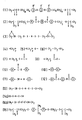
- Suitable liquid crystalline di-acrylates are shown in general formula 1 of the formula sheet.
- R is a hydrogen atom or a methyl group
- R′ is a hydrogen atom, an alkyl group having 1-4 carbon atoms or a halogen atom
- A is an oxygen atom or the group -O- -
- B is the group -O- - or - -O
- m has the value 1-15
- n is 0 or 1.
- An exponent of these di-(meth)acrylates is shown in formula 2 of the formula sheet.
- suitable liquid crystalline di-(meth)acrylates are stated, in, for example, European Patent Application EP 261712 (PHN 11.855), wherein the method of preparation is also described.
- Other suitable liquid crystalline monomers are epoxides which are represented by formula 3 of the formula sheet.
- X is a group which is represented by one of the formulae 4 up to and including 8 of the formula sheet, wherein p has a value of from 0-20
- M is a mesogenic group, a few examples of which are represented by formulae 9 up to and including 12 of the formula sheet.
- suitable liquid crystalline monomers are vinyl ethers and thiolene systems which are represented by the formulae 13 and 14a, 14b, respectively, of the formula sheet.
- X and X′ have the above-stated meaning of X and M and M′ have the above-stated meaning of M.
- the value of p is 0-20.
- the liquid crystalline monomers are mixed with 1 to 2% by weight of a radical initiator such as, for example, Darocur 1173 (Merck; formula 16 of the formula sheet) and Irgacure 651 (Ciba-Geigy; formula 17 of the formula sheet) which are both photoinitiators or benzoyl peroxide which is a thermal initiator.
- a radical initiator such as, for example, Darocur 1173 (Merck; formula 16 of the formula sheet) and Irgacure 651 (Ciba-Geigy; formula 17 of the formula sheet) which are both photoinitiators or benzoyl peroxide which is a thermal initiator.
- Cationic initiators for example Degacure KI 85 (Degusa; formula 18 of the formula sheet) are used to cure epoxides and vinyl ethers.
- a preferred embodiment of the method is characterized in that the liquid crystalline monomers are oriented by an external field of force before the adhesive is left to cure.
- the external field of force may be an electric or magnetic field whose direction can be readily adjusted, so that any specific orientation of the liquid crystalline monomers can be obtained. It is also possible to previously rub the surface to be cemented in one direction, so that the liquid crystalline monomers will be oriented in the direction of rubbing.
- the surface to be cemented may be first provided with a suitable polymer orientation layer such as polyimide.
- the liquid crystalline monomers can alternatively be oriented by previously providing microgrooves or a silane on the surface to be cemented. During polymerization, the field is maintained so that the molecules cannot become disoriented. Due to the additional ordering, the linear shrinkage perpendicular to the direction of orientation is less than the linear shrinkage in the direction of orientation. This can be attributed to the fact that in the direction perpendicular to the direction of orientation the monomer molecules are already densely packed, which hardly changes by polymerization. In many applications the inaccuracies or stressses are introduced by the linear shrinkage in one or two directions, so that the orientation of the monomers can be dramatically improved by applying the proper external field of force.
- a practical embodiment of the method according to the invention is characterized in that the curing is carried out by means of exposure to UV light.
- the adhesive comprising liquid crystalline monomers contains an above-mentioned radical or cationic photoinitiator.
- the photoinitiator decomposes into radicals or in a cation which initiate(s) polymerization of the monomers.
- the use of UV light of course requires that at least one of the bodies to be cemented is transparent to UV light or that the adhesive layer is otherwise accessible to UV light. In the case of applications in optical assemblies this requirement is mostly fulfilled.
- the invention further relates to a composite body comprising at least two parts, at least two parts of which are bonded by means of an adhesive bond, and is characterized in that the adhesive bond comprises an oriented polymer.
- the orientation of the polymer is selected such that shrinkage and shrinkage stresses are least desirable in directions perpendicular to the orientation of the polymer.
- the two parts of the composite body exhibit a high degree of positioning accuracy relative to one another because of the very small shrinkage during curing in the directions which are important to the positioning.
- the shrinkage stress in the adhesive layer is also very small.
- Such accuracies are important in the above-mentioned optical disc players such as Laser Vision and Compact-Disc players in which positional accuracies of a few tenths of one micron and angular accuracies of 10 ⁇ 4 to 10 ⁇ 6 rad. are required.
- optical components such as lenses, mirrors, prisms and lasers in a suitable mount are concerned.
- the liquid crystalline monomers can be cured by using a thermal initiator such as benzoyl peroxide.
- adhesion promoters may be added, for example silanes.
- reference numeral 1 denotes a section of an optical assembly 1 comprising a synthetic resin mount 3 (polypropylene oxide) and a glass lens 5 having an optical axis 6.
- An adhesive is prepared which consists of a compound of formula 2 of the formula sheet and 2% by weight of Darocur 1173 (Merck). The adhesive has liquid crystalline nematic properties in the temperature range of from 78 to 161 o C.
- An inner wall 7 of the mount is rubbed with a non-fluff velvet cloth in a direction Z which extends parallel to the optical axis.
- a cartesian coordinates system is shown at one side of the drawing, wherein 2 extends parallel to the direction of the optical axis 6.
- the lens is positioned in the mount in a customary manner.
- An adhesive layer 9 is present between the periphery of the lens and the inner wall of the mount.
- the assembly 1 is then heated to a temperature of 80 o C.
- the monomers in the adhesive layer become oriented in the direction of rubbing 2.
- the adhesive layer is exposed to UV light of 360 nm for several minutes.
- the U.V.-light power of the low-pressure mercury-vapour lamp to which the adhjesive is exposed is 5 mW/cm2.
- the monomer molecules in the adhesive layer 9 which are oriented in the direction of rubbing, thereby fixing the orientation.
- the molecular axes of the polymer molecules are directed in the direction of rubbing Z. Due to the fact that the shrinkage perpendicular to the molecular axis is small, the polymerization shrinkage in two of the three main directions is small, namely in the X and Y direction. By choosing the direction of orientation of the molecules, it becomes possible to select a surface having little shrinkage in both directions.
- the polymerization shrinkage of curing monomers is measured by means of an arrangement as shown in Fig. 2.
- a glass plate 3 is located on a heating stage 1.
- a spacer 5 having a thickness of 450 ⁇ m is arranged on the glass plate along the periphery.
- a thin reflecting metallized glass plate 7 is provided on the spacer.
- the adhesive has the same composition as in example 1.
- the volume of the drop of adhesive is 0.002 cm3.
- the drop contacts both the glass plate 3 and the metallized glass plate 7.
- the entire arrangement may be located between magnet poles (not shown) having a field strength of 10 kGauss.
- the Table lists the results of the polymerization-shrinkage measurements. Column 2 lists the linear shrinkage when no external magnetic field is applied; columns 3 and 4 list the linear shrinkage parallel and perpendicular, respectively, to the molecular axis when an external magnetic field is applied, and column 5 lists the volume shrinkage.
- the volume shrinkage can be calculated from the individual values of the three main directions.
- the Table lists the measured values of an allied non-liquid crystalline monomer, namely Diacryl 101 (Akzo). This monomer is shown in formula 15 of the formula sheet.
Abstract
Description
- The invention relates to a method of bonding two bodies using an adhesive, in which adhesive is applied between the two bodies which are then positioned relative to one another, after which the adhesive is made to cure.
- The invention also relates to a composite body comprising at least two parts, at least two parts of which are bonded by means of an adhesive bond.
- A method of bonding two bodies, one body being an optical component such as a mirror or lens, and the other body being a mount, is described in European Patent Specification EP 0090218. The mount is provided with a bore in which the optical component is fitted, a slot being formed between the inner wall of the mount and the outer wall of the optical component. This slot is completely or partly filled with adhesive.
- Such optical assemblies are used, for example, in optical disc players. In these devices it is important that the optical parts are properly positioned relative to each other. Important in this connection is the positioning accuracy in the direction of the optical axis (Z-direction) of the optical assembly, in the directions of two axes (X- and Y-direction) extending perpendicularly to the optical axis and to one another, and in the directions of rotation about the latter axes.
- The well-known method has the disadvantage that the curing of the adhesive between the optical component and the mount may bring about relatively large displacements of the optical component in the Z-direction due to the inevitable shrinkage of the adhesive layer during curing. Moreover, due to the occurrence of shrinkage stresses in the layer of adhesive there is a considerable chance that the optical component will tilt about the axes extending in the X- and Y-direction. In general, chemically-hardening adhesives comprising no or little solvent are used to cement such optical components to each other, which adhesives are based on a polymerization reaction of reactive monomers or oligomers. During this polymerization or curing reaction, which can be induced by light or heat, a volume reduction of the adhesive layer occurs which leads to shrinkage and shrinkage stresses in the adhesive layer. In order to manufacture accurate optical assemblies, so far, mechanical measures have been proposed, as described in U.S. Patent 4,750,826, in which one of the walls to be cemented comprises ribs to which adhesive is applied. In U.S. Patent 4,776,670 a description is given of a holder which is triangular in cross-section and which has deformable side walls. In the U.S. Patent 4,818,069 it is stated that profiles are provided in the surfaces to be cemented. These mechanical solutions, however, do not solve the underlying cause of the problem, namely the shrinkage of the adhesive layer during curing.
- It is an object of the invention, inter alia, to provide a method of the type mentioned in the opening paragraph, in which the two bodies to be cemented to each other are very accurately positioned relative to one another because the shrinkage and shrinkage stresses in the adhesive layer are small.
- According to the invention, this object is achieved by a method as described in the opening paragraph, which is characterized in that the adhesive comprises liquid crystalline monomers. The advantage of using liquid crystalline monomers is that the monomers order themselves relative to each other, so that prior to polymerization they have a higher density than the customary isotropic monomers. Due to this, this type of materials has a smaller overall volume shrinkage than polymerized isotropic monomers.
- The adhesive which comprises liquid crystalline monomers is applied in a customary manner by applying one or more drops to a surface of one or both of the bodies to be joined. In the case of a narrow slit between the two bodies to be joined, use can be made of the capillary action of the slit.
- According to the invention, a suitable embodiment of the method is characterized in that a di-(meth)acrylate is used as the liquid crystalline monomer. Suitable liquid crystalline di-acrylates are shown in
general formula 1 of the formula sheet. In this formula:
R is a hydrogen atom or a methyl group,
R′ is a hydrogen atom, an alkyl group having 1-4 carbon atoms or a halogen atom,
A is an oxygen atom or the group
-O--,
B is the group
-O-- or - -O,
-O,
m has the value 1-15
n is 0 or 1.
An exponent of these di-(meth)acrylates is shown informula 2 of the formula sheet. Other suitable liquid crystalline di-(meth)acrylates are stated, in, for example, European Patent Application EP 261712 (PHN 11.855), wherein the method of preparation is also described. Other suitable liquid crystalline monomers are epoxides which are represented byformula 3 of the formula sheet. Informula 3, X is a group which is represented by one of the formulae 4 up to and including 8 of the formula sheet, wherein p has a value of from 0-20, and M is a mesogenic group, a few examples of which are represented byformulae 9 up to and including 12 of the formula sheet. Other suitable liquid crystalline monomers are vinyl ethers and thiolene systems which are represented by theformulae formulae - To initiate the polymerization reaction of the (meth)acrylates and thiolene systems, the liquid crystalline monomers are mixed with 1 to 2% by weight of a radical initiator such as, for example, Darocur 1173 (Merck;
formula 16 of the formula sheet) and Irgacure 651 (Ciba-Geigy;formula 17 of the formula sheet) which are both photoinitiators or benzoyl peroxide which is a thermal initiator. Cationic initiators, for example Degacure KI 85 (Degusa;formula 18 of the formula sheet) are used to cure epoxides and vinyl ethers. - According to the invention, a preferred embodiment of the method is characterized in that the liquid crystalline monomers are oriented by an external field of force before the adhesive is left to cure. Because of the high mobility of the relatively small molecules of the liquid crystalline monomers a very rapid substantially instantaneous further orientation of the molecules can be obtained by using an external field of force. The external field of force may be an electric or magnetic field whose direction can be readily adjusted, so that any specific orientation of the liquid crystalline monomers can be obtained. It is also possible to previously rub the surface to be cemented in one direction, so that the liquid crystalline monomers will be oriented in the direction of rubbing. The surface to be cemented may be first provided with a suitable polymer orientation layer such as polyimide. The liquid crystalline monomers can alternatively be oriented by previously providing microgrooves or a silane on the surface to be cemented. During polymerization, the field is maintained so that the molecules cannot become disoriented. Due to the additional ordering, the linear shrinkage perpendicular to the direction of orientation is less than the linear shrinkage in the direction of orientation. This can be attributed to the fact that in the direction perpendicular to the direction of orientation the monomer molecules are already densely packed, which hardly changes by polymerization. In many applications the inaccuracies or stressses are introduced by the linear shrinkage in one or two directions, so that the orientation of the monomers can be dramatically improved by applying the proper external field of force.
- A practical embodiment of the method according to the invention is characterized in that the curing is carried out by means of exposure to UV light. For this purpose, the adhesive comprising liquid crystalline monomers contains an above-mentioned radical or cationic photoinitiator. As a result of exposure the photoinitiator decomposes into radicals or in a cation which initiate(s) polymerization of the monomers. The use of UV light of course requires that at least one of the bodies to be cemented is transparent to UV light or that the adhesive layer is otherwise accessible to UV light. In the case of applications in optical assemblies this requirement is mostly fulfilled.
- The invention further relates to a composite body comprising at least two parts, at least two parts of which are bonded by means of an adhesive bond, and is characterized in that the adhesive bond comprises an oriented polymer. The orientation of the polymer is selected such that shrinkage and shrinkage stresses are least desirable in directions perpendicular to the orientation of the polymer. To obtain an oriented polymer the above-mentioned methods may be applied. The two parts of the composite body exhibit a high degree of positioning accuracy relative to one another because of the very small shrinkage during curing in the directions which are important to the positioning. The shrinkage stress in the adhesive layer is also very small. Such accuracies are important in the above-mentioned optical disc players such as Laser Vision and Compact-Disc players in which positional accuracies of a few tenths of one micron and angular accuracies of 10⁻⁴ to 10⁻⁶ rad. are required. In this case, optical components such as lenses, mirrors, prisms and lasers in a suitable mount are concerned.
- Although the said examples are all about optical assemblies, it will be obvious to those skilled in the art that the method according to the invention can also be applied to all adhesive bonds which require a high positioning accuracy. As has been stated above, in the case of untransparent bodies the liquid crystalline monomers can be cured by using a thermal initiator such as benzoyl peroxide. To improve adhesion, adhesion promoters may be added, for example silanes.
- The invention will be explained in greater detail by means of exemplary embodiments and with reference to the accompanying drawings, in which
- Fig. 1 is a diagrammatic sectional view of an optical assembly, and
- Fig. 2 diagrammatically shows an arrangement for measuring the shrinkage of the curing adhesive.
- In Fig. 1,
reference numeral 1 denotes a section of anoptical assembly 1 comprising a synthetic resin mount 3 (polypropylene oxide) and a glass lens 5 having anoptical axis 6. An adhesive is prepared which consists of a compound offormula 2 of the formula sheet and 2% by weight of Darocur 1173 (Merck). The adhesive has liquid crystalline nematic properties in the temperature range of from 78 to 161o C. Aninner wall 7 of the mount is rubbed with a non-fluff velvet cloth in a direction Z which extends parallel to the optical axis. A cartesian coordinates system is shown at one side of the drawing, wherein 2 extends parallel to the direction of theoptical axis 6. Instead of velvet, other materials such as paper gauze or coton may alternatively be used. After the said adhesive is provided on the periphery of the lens, the lens is positioned in the mount in a customary manner. Anadhesive layer 9 is present between the periphery of the lens and the inner wall of the mount. Theassembly 1 is then heated to a temperature of 80o C. The monomers in the adhesive layer become oriented in the direction of rubbing 2. Subsequently, the adhesive layer is exposed to UV light of 360 nm for several minutes. The U.V.-light power of the low-pressure mercury-vapour lamp to which the adhjesive is exposed is 5 mW/cm². As a result of exposure the monomer molecules in theadhesive layer 9 which are oriented in the direction of rubbing, thereby fixing the orientation. The molecular axes of the polymer molecules are directed in the direction of rubbing Z. Due to the fact that the shrinkage perpendicular to the molecular axis is small, the polymerization shrinkage in two of the three main directions is small, namely in the X and Y direction. By choosing the direction of orientation of the molecules, it becomes possible to select a surface having little shrinkage in both directions. - The polymerization shrinkage of curing monomers is measured by means of an arrangement as shown in Fig. 2. A
glass plate 3 is located on aheating stage 1. A spacer 5 having a thickness of 450 µm is arranged on the glass plate along the periphery. After a drop of the adhesive 9 to be measured is applied to the glass plate, a thin reflecting metallizedglass plate 7 is provided on the spacer. The adhesive has the same composition as in example 1. The volume of the drop of adhesive is 0.002 cm³. The drop contacts both theglass plate 3 and the metallizedglass plate 7. By means of the heating stage the temperature of the drop is increased to 100o C. The entire arrangement may be located between magnet poles (not shown) having a field strength of 10 kGauss. Measurements conducted by means of a polarizing microscope have shown that this field strength is sufficient to orient the liquid crystalline monomers. The drop is exposed by means of a low-pressuremercury vapour lamp 11 which emitsUV light 13 having a wavelength of 360 nm. The UV light reaches the drop via anaperture 15 in the heating stage and viaglas plate 3. As a result of the exposure the oriented monomer molecules in the drop are polymerized, thereby fixing the orientation. The drop is subject to shrinkage caused by the polymerization, which will cause the metallizedglass plate 7 to become curved. This curvature is recorded by means of aninterferometer 17. The curvature of the metallized glass plate is a criterion of the amount of shrinkage. - The Table lists the results of the polymerization-shrinkage measurements.
Column 2 lists the linear shrinkage when no external magnetic field is applied;columns 3 and 4 list the linear shrinkage parallel and perpendicular, respectively, to the molecular axis when an external magnetic field is applied, and column 5 lists the volume shrinkage. The volume shrinkage can be calculated from the individual values of the three main directions. By way of comparative example, the Table lists the measured values of an allied non-liquid crystalline monomer, namely Diacryl 101 (Akzo). This monomer is shown informula 15 of the formula sheet.Table Material Linear shrinkage (%) Volume shrinkage % unoriented oriented // mol. axis ┴ mol. axis Monomer acc. to formula 22,1 3,9 1,2 6,3 Diacryl 101 4,0 4,0 4,0 12,0 - Measurements have shown that the linear shrinkage is small when liquid crystalline monomers are used to which no external field of force is applied, and that after the application of an external field of force, which brings about additional orientation, in particular the linear shrinkage perpendicular to the molecular axis is very small. By choosing the direction of orientation, a surface can be selected having a very small shrinkage in both directions. According to the Table, the linear shrinkage in said surface upon polymerization at 100o C will not be 4% as in the case of Diacryl 101 but only 1.2%.
Claims (5)
Applications Claiming Priority (2)
| Application Number | Priority Date | Filing Date | Title |
|---|---|---|---|
| NL8802683A NL8802683A (en) | 1988-11-02 | 1988-11-02 | METHOD FOR JOINING TWO BODIES WITH AN ADHESIVE AND A COMPOSITE BODY. |
| NL8802683 | 1988-11-02 |
Publications (2)
| Publication Number | Publication Date |
|---|---|
| EP0367341A1 true EP0367341A1 (en) | 1990-05-09 |
| EP0367341B1 EP0367341B1 (en) | 1993-05-19 |
Family
ID=19853147
Family Applications (1)
| Application Number | Title | Priority Date | Filing Date |
|---|---|---|---|
| EP89202718A Expired - Lifetime EP0367341B1 (en) | 1988-11-02 | 1989-10-27 | Method of bonding two bodies using an adhesive, which adhesive comprises liquid crystalline monomers |
Country Status (5)
| Country | Link |
|---|---|
| EP (1) | EP0367341B1 (en) |
| JP (1) | JPH02170881A (en) |
| KR (1) | KR0133284B1 (en) |
| DE (1) | DE68906642T2 (en) |
| NL (1) | NL8802683A (en) |
Cited By (3)
| Publication number | Priority date | Publication date | Assignee | Title |
|---|---|---|---|---|
| US5375138A (en) * | 1992-09-25 | 1994-12-20 | International Business Machines Corporation | Optical cavities for lasers |
| US6031015A (en) * | 1995-07-18 | 2000-02-29 | Ivoclar Ag | Dental materials based on liquid crystalline monomers |
| WO2000077561A2 (en) * | 1999-06-15 | 2000-12-21 | Institut 'jožef Stefan' | Process for manufacturing a polymer compensation layer for an lcd, and construction of an lcd |
Families Citing this family (4)
| Publication number | Priority date | Publication date | Assignee | Title |
|---|---|---|---|---|
| JPH0541408A (en) * | 1991-08-05 | 1993-02-19 | Rohm Co Ltd | Bonding method |
| US5998499A (en) | 1994-03-25 | 1999-12-07 | Dentsply G.M.B.H. | Liquid crystalline (meth)acrylate compounds, composition and method |
| DE102015118100A1 (en) * | 2015-10-23 | 2017-04-27 | Hella Kgaa Hueck & Co. | Connecting arrangement for the adhesive connection of a position-sensitive element with a receiving body |
| KR20200031228A (en) | 2018-09-14 | 2020-03-24 | 최종갑 | Apparatus for discharging dough |
Citations (10)
| Publication number | Priority date | Publication date | Assignee | Title |
|---|---|---|---|---|
| GB1419634A (en) * | 1972-05-15 | 1975-12-31 | Ciba Geigy Ag | Method of bonding surfaces together using adhesive compositons |
| GB1488354A (en) * | 1975-02-07 | 1977-10-12 | Ogden & Wheldon Ltd | Anaerobic curable compositions |
| US4181752A (en) * | 1974-09-03 | 1980-01-01 | Minnesota Mining And Manufacturing Company | Acrylic-type pressure sensitive adhesives by means of ultraviolet radiation curing |
| US4281152A (en) * | 1980-06-20 | 1981-07-28 | Gulf Oil Corporation | Acrylate monomers and photopolymerizable compositions containing same |
| EP0090218A1 (en) * | 1982-03-31 | 1983-10-05 | Firma Carl Zeiss | Method and apparatus for adjusting and mounting optical components in optical instruments |
| EP0138326A1 (en) * | 1983-08-19 | 1985-04-24 | RAYCHEM CORPORATION (a California corporation) | Method & composition for joining optical fibres |
| EP0206397A1 (en) * | 1985-06-10 | 1986-12-30 | Koninklijke Philips Electronics N.V. | Replica lens |
| EP0268886A2 (en) * | 1986-11-07 | 1988-06-01 | Tremco Incorporated | Flexible preformed adhesive strip, window structure and laminate |
| EP0282280A1 (en) * | 1987-03-09 | 1988-09-14 | Mitsui Petrochemical Industries, Ltd. | Curable adhesive compositions |
| EP0140006B1 (en) * | 1983-09-06 | 1989-11-15 | Gerhard Dr. Piestert | Sealing material curing in oxygen-free conditions for surface and thread sealing |
-
1988
- 1988-11-02 NL NL8802683A patent/NL8802683A/en not_active Application Discontinuation
-
1989
- 1989-10-27 EP EP89202718A patent/EP0367341B1/en not_active Expired - Lifetime
- 1989-10-27 DE DE89202718T patent/DE68906642T2/en not_active Expired - Fee Related
- 1989-10-30 KR KR1019890015623A patent/KR0133284B1/en not_active IP Right Cessation
- 1989-10-31 JP JP1282060A patent/JPH02170881A/en active Pending
Patent Citations (10)
| Publication number | Priority date | Publication date | Assignee | Title |
|---|---|---|---|---|
| GB1419634A (en) * | 1972-05-15 | 1975-12-31 | Ciba Geigy Ag | Method of bonding surfaces together using adhesive compositons |
| US4181752A (en) * | 1974-09-03 | 1980-01-01 | Minnesota Mining And Manufacturing Company | Acrylic-type pressure sensitive adhesives by means of ultraviolet radiation curing |
| GB1488354A (en) * | 1975-02-07 | 1977-10-12 | Ogden & Wheldon Ltd | Anaerobic curable compositions |
| US4281152A (en) * | 1980-06-20 | 1981-07-28 | Gulf Oil Corporation | Acrylate monomers and photopolymerizable compositions containing same |
| EP0090218A1 (en) * | 1982-03-31 | 1983-10-05 | Firma Carl Zeiss | Method and apparatus for adjusting and mounting optical components in optical instruments |
| EP0138326A1 (en) * | 1983-08-19 | 1985-04-24 | RAYCHEM CORPORATION (a California corporation) | Method & composition for joining optical fibres |
| EP0140006B1 (en) * | 1983-09-06 | 1989-11-15 | Gerhard Dr. Piestert | Sealing material curing in oxygen-free conditions for surface and thread sealing |
| EP0206397A1 (en) * | 1985-06-10 | 1986-12-30 | Koninklijke Philips Electronics N.V. | Replica lens |
| EP0268886A2 (en) * | 1986-11-07 | 1988-06-01 | Tremco Incorporated | Flexible preformed adhesive strip, window structure and laminate |
| EP0282280A1 (en) * | 1987-03-09 | 1988-09-14 | Mitsui Petrochemical Industries, Ltd. | Curable adhesive compositions |
Cited By (4)
| Publication number | Priority date | Publication date | Assignee | Title |
|---|---|---|---|---|
| US5375138A (en) * | 1992-09-25 | 1994-12-20 | International Business Machines Corporation | Optical cavities for lasers |
| US6031015A (en) * | 1995-07-18 | 2000-02-29 | Ivoclar Ag | Dental materials based on liquid crystalline monomers |
| WO2000077561A2 (en) * | 1999-06-15 | 2000-12-21 | Institut 'jožef Stefan' | Process for manufacturing a polymer compensation layer for an lcd, and construction of an lcd |
| WO2000077561A3 (en) * | 1999-06-15 | 2002-05-23 | Inst Stefan Jozef | Process for manufacturing a polymer compensation layer for an lcd, and construction of an lcd |
Also Published As
| Publication number | Publication date |
|---|---|
| DE68906642T2 (en) | 1993-12-09 |
| DE68906642D1 (en) | 1993-06-24 |
| JPH02170881A (en) | 1990-07-02 |
| NL8802683A (en) | 1990-06-01 |
| KR0133284B1 (en) | 1998-04-14 |
| KR900007992A (en) | 1990-06-02 |
| EP0367341B1 (en) | 1993-05-19 |
Similar Documents
| Publication | Publication Date | Title |
|---|---|---|
| US5178710A (en) | Bonding using a difunctional liquid crystalline monomer adhesive under an applied force field | |
| KR100890662B1 (en) | Manufacture of optical element | |
| RU2444538C1 (en) | Epoxy composition for polymerisation and sealing compound containing said composition | |
| TWI712636B (en) | Liquid crystal cured film, optical film including the liquid crystal cured film, and display device | |
| EP0587280B1 (en) | Antiferroelectric liquid crystal composite material, process for preparing the same, and liquid crystal element using the same | |
| KR100839261B1 (en) | Optical device | |
| JP4087205B2 (en) | Optical film for liquid crystal display element and liquid crystal display element equipped with the film | |
| KR101676894B1 (en) | Liquid Crystal Film | |
| KR20130020616A (en) | Polarizer | |
| EP0367341B1 (en) | Method of bonding two bodies using an adhesive, which adhesive comprises liquid crystalline monomers | |
| JP2009227667A (en) | Compound, and optical film containing the compound | |
| EP1690918A2 (en) | Liquid crystal optical element and method for its production | |
| KR19990023378A (en) | Liquid crystalline composition, hardened | cured material, and its manufacturing method | |
| JP4246536B2 (en) | Liquid crystal film and liquid crystal display element equipped with the film | |
| JP5209223B2 (en) | Film, film manufacturing method, and use thereof | |
| JP2007169172A (en) | Method for purifying epoxy resin, adhesive for optical member and method for producing optical member | |
| EP2098544A1 (en) | Polymerizable compounds and polymerizable compositions | |
| JP3879109B2 (en) | Optical adhesive and optical component using the same | |
| KR101689900B1 (en) | Retardation element | |
| EP0423880B1 (en) | Molecularly oriented synthetic resin composition | |
| JP2008089894A (en) | Method for manufacturing retardation filmmethod for manufacturing retardation film | |
| JP3617653B2 (en) | Method for producing substrate having optical anisotropy | |
| EP1291404A1 (en) | Optical adhesive composition and optical apparatus | |
| JP2007284500A (en) | Adhesive for optical part | |
| JP2004339246A (en) | Ultraviolet curing type epoxy resin composition |
Legal Events
| Date | Code | Title | Description |
|---|---|---|---|
| PUAI | Public reference made under article 153(3) epc to a published international application that has entered the european phase |
Free format text: ORIGINAL CODE: 0009012 |
|
| AK | Designated contracting states |
Kind code of ref document: A1 Designated state(s): CH DE FR GB IT LI NL SE |
|
| 17P | Request for examination filed |
Effective date: 19901107 |
|
| 17Q | First examination report despatched |
Effective date: 19920302 |
|
| GRAA | (expected) grant |
Free format text: ORIGINAL CODE: 0009210 |
|
| AK | Designated contracting states |
Kind code of ref document: B1 Designated state(s): CH DE FR GB IT LI NL SE |
|
| PG25 | Lapsed in a contracting state [announced via postgrant information from national office to epo] |
Ref country code: IT Free format text: LAPSE BECAUSE OF FAILURE TO SUBMIT A TRANSLATION OF THE DESCRIPTION OR TO PAY THE FEE WITHIN THE PRE;WARNING: LAPSES OF ITALIAN PATENTS WITH EFFECTIVE DATE BEFORE 2007 MAY HAVE OCCURRED AT ANY TIME BEFORE 2007. THE CORRECT EFFECTIVE DATE MAY BE DIFFERENT FROM THE ONE RECORDED.SCRIBED TIME-LIMIT Effective date: 19930519 Ref country code: SE Effective date: 19930519 |
|
| REF | Corresponds to: |
Ref document number: 68906642 Country of ref document: DE Date of ref document: 19930624 |
|
| ET | Fr: translation filed | ||
| PLBE | No opposition filed within time limit |
Free format text: ORIGINAL CODE: 0009261 |
|
| STAA | Information on the status of an ep patent application or granted ep patent |
Free format text: STATUS: NO OPPOSITION FILED WITHIN TIME LIMIT |
|
| 26N | No opposition filed | ||
| REG | Reference to a national code |
Ref country code: CH Ref legal event code: PFA Free format text: PHILIPS ELECTRONICS N.V. |
|
| REG | Reference to a national code |
Ref country code: FR Ref legal event code: CD |
|
| NLT1 | Nl: modifications of names registered in virtue of documents presented to the patent office pursuant to art. 16 a, paragraph 1 |
Owner name: PHILIPS ELECTRONICS N.V. |
|
| PGFP | Annual fee paid to national office [announced via postgrant information from national office to epo] |
Ref country code: GB Payment date: 19970930 Year of fee payment: 9 |
|
| PGFP | Annual fee paid to national office [announced via postgrant information from national office to epo] |
Ref country code: FR Payment date: 19971021 Year of fee payment: 9 |
|
| PGFP | Annual fee paid to national office [announced via postgrant information from national office to epo] |
Ref country code: NL Payment date: 19971030 Year of fee payment: 9 |
|
| PGFP | Annual fee paid to national office [announced via postgrant information from national office to epo] |
Ref country code: DE Payment date: 19971219 Year of fee payment: 9 |
|
| PGFP | Annual fee paid to national office [announced via postgrant information from national office to epo] |
Ref country code: CH Payment date: 19980115 Year of fee payment: 9 |
|
| REG | Reference to a national code |
Ref country code: FR Ref legal event code: CD |
|
| PG25 | Lapsed in a contracting state [announced via postgrant information from national office to epo] |
Ref country code: GB Free format text: LAPSE BECAUSE OF NON-PAYMENT OF DUE FEES Effective date: 19981027 |
|
| PG25 | Lapsed in a contracting state [announced via postgrant information from national office to epo] |
Ref country code: CH Free format text: LAPSE BECAUSE OF THE APPLICANT RENOUNCES Effective date: 19981031 Ref country code: LI Free format text: LAPSE BECAUSE OF THE APPLICANT RENOUNCES Effective date: 19981031 |
|
| REG | Reference to a national code |
Ref country code: CH Ref legal event code: PL |
|
| PG25 | Lapsed in a contracting state [announced via postgrant information from national office to epo] |
Ref country code: NL Free format text: LAPSE BECAUSE OF NON-PAYMENT OF DUE FEES Effective date: 19990501 |
|
| GBPC | Gb: european patent ceased through non-payment of renewal fee |
Effective date: 19981027 |
|
| PG25 | Lapsed in a contracting state [announced via postgrant information from national office to epo] |
Ref country code: FR Free format text: LAPSE BECAUSE OF NON-PAYMENT OF DUE FEES Effective date: 19990630 |
|
| NLV4 | Nl: lapsed or anulled due to non-payment of the annual fee |
Effective date: 19990501 |
|
| REG | Reference to a national code |
Ref country code: FR Ref legal event code: ST |
|
| PG25 | Lapsed in a contracting state [announced via postgrant information from national office to epo] |
Ref country code: DE Free format text: LAPSE BECAUSE OF NON-PAYMENT OF DUE FEES Effective date: 19990803 |