EP0367422A1 - Closure for container - Google Patents
Closure for container Download PDFInfo
- Publication number
- EP0367422A1 EP0367422A1 EP89310334A EP89310334A EP0367422A1 EP 0367422 A1 EP0367422 A1 EP 0367422A1 EP 89310334 A EP89310334 A EP 89310334A EP 89310334 A EP89310334 A EP 89310334A EP 0367422 A1 EP0367422 A1 EP 0367422A1
- Authority
- EP
- European Patent Office
- Prior art keywords
- wall member
- obstructor
- closure assembly
- configuration
- pin means
- Prior art date
- Legal status (The legal status is an assumption and is not a legal conclusion. Google has not performed a legal analysis and makes no representation as to the accuracy of the status listed.)
- Granted
Links
Images
Classifications
-
- A—HUMAN NECESSITIES
- A61—MEDICAL OR VETERINARY SCIENCE; HYGIENE
- A61M—DEVICES FOR INTRODUCING MEDIA INTO, OR ONTO, THE BODY; DEVICES FOR TRANSDUCING BODY MEDIA OR FOR TAKING MEDIA FROM THE BODY; DEVICES FOR PRODUCING OR ENDING SLEEP OR STUPOR
- A61M5/00—Devices for bringing media into the body in a subcutaneous, intra-vascular or intramuscular way; Accessories therefor, e.g. filling or cleaning devices, arm-rests
- A61M5/178—Syringes
- A61M5/31—Details
- A61M5/32—Needles; Details of needles pertaining to their connection with syringe or hub; Accessories for bringing the needle into, or holding the needle on, the body; Devices for protection of needles
- A61M5/3205—Apparatus for removing or disposing of used needles or syringes, e.g. containers; Means for protection against accidental injuries from used needles
-
- A—HUMAN NECESSITIES
- A61—MEDICAL OR VETERINARY SCIENCE; HYGIENE
- A61B—DIAGNOSIS; SURGERY; IDENTIFICATION
- A61B50/00—Containers, covers, furniture or holders specially adapted for surgical or diagnostic appliances or instruments, e.g. sterile covers
- A61B2050/005—Containers, covers, furniture or holders specially adapted for surgical or diagnostic appliances or instruments, e.g. sterile covers with a lid or cover
- A61B2050/0051—Containers, covers, furniture or holders specially adapted for surgical or diagnostic appliances or instruments, e.g. sterile covers with a lid or cover closable by rotation
- A61B2050/0054—Containers, covers, furniture or holders specially adapted for surgical or diagnostic appliances or instruments, e.g. sterile covers with a lid or cover closable by rotation about the central longitudinal axis perpendicular to the lid plane
Definitions
- the present invention relates to a closure for a container, particularly a disposable container. It further relates to a container including such a closure.
- WO 88/00067 discloses a container for used syringe needles closed at the top by a plate with an aperture.
- An apertured cap is rotatably mounted over the plate so that its aperture can be moved into and out of register with the plate's aperture. This is for gripping a needle projecting through the apertures. It is stated that a further position or positions may be provided whereby the cap can be rotated to a "locked" position with respect to the plate when the container is full. However, there is no disclosure of how this could be effected. Furthermore, there is no disclosure of means for restraining removal of the plate and cap.
- the invention concerns a closure for a container comprising means defining an opening; a closure member displaceable to obstruct or reveal the opening; and locking means operable to lock the closure in its obstructing configuration.
- the opening may be defined in a surface over which the closure member is adapted to slide.
- the closure member may carry a locking pin adapted to be moved irreversibly to engage a detent formation in the surface, so as to prevent the sliding of the closure member away from the main access opening. (Alternatively, the pin could be borne by the surface member, and engage a detent formation of the closure member.)
- the invention provides a closure assembly for a container, comprising a wall member for connection to a mouth of a container, the wall member having an access aperture; and an obstructor member coupled to the wall member so as to be displaceable between an obstructing configuration in which it obstructs the access aperture, and an open configuration in which any obstruction by it of the access aperture is less than in the obstructing configuration; characterised in that the closure assembly includes a locking piece which is displaceable to lock the obstructor member in its obstructing configuration and restrain its return to its open configuration.
- the invention provides a container having such a closure assembly, connected or connectable so as to be difficult or impossible to detach from the body of the container.
- a container 10 (whose body 12 is shown schematically in Fig. 2) has an upper wall member or lid 14 whose mouth has a downwardly open channel 16 with an inwardly directed bead 18 for snap-engaging a complementary formation at the top of the body 12 (not shown).
- the upper face of the lid 14 has a recessed circular portion 20 penetrated by an access aperture 22.
- the aperture 22 is approximately elliptical. It may include a narrow extension 24 projecting into a region 26 where the lid 14 is of reduced thickness. This inlet 24 provides a means for detaching needles from hypodermic syringes.
- the recess 20 has an arcuate depression 28, which is of uniform depth except for a deep aperture 30 at the end nearest the opening 22.
- an upstanding pillar 32 which has a projecting bead 34 adjacent its top.
- Figs. 3 and 4 show an obstructor member 38 in the form of a disc dimensioned to fit within the recess 20.
- the disc has a peripheral upturned lip 40 and a central upturned wall portion 42 defining a bushing having a central aperture 44. This is dimensioned so that the disc 38 can fit into the recess 20, with the pillar 32 extending through the aperture 44.
- the disc is a push-fit, such that the bead 34 snap-engages above the bushing 42, to retain the disc rotatably on the lid.
- the disc has a large aperture 46 similar to the access opening 22 and thinned area 26 of the lid, with which it can be brought into register by rotation.
- the disc has a handgrip 50 defined by a frustoconical wall with external serrations 52.
- the wall 50 has an upper portion whose internal surface is formed with a vertically spaced pair of annular recesses 53,54. Beneath them there is a radially extending annular wall 56, leading to a central tubular portion 58.
- a locking pin 60 has a shank 62 dimensioned to be slidable within the tube 58 so that it can project beneath the tube 58 by variable amounts.
- the pin 60 has a head 64 including a radially outer curved bead portion 66. This is shaped and dimensioned so that it can locate in the upper annular groove 53. In this configuration, the shank 62 projects a short way beneath the tubular portion 58 and the rest of the disc 38. The projecting end portion extends into the arcuate recess 28, and thus guides and delimits the rotation of the disc.
- the pin 60 is at the right-hand end of the arcuate recess 28, as seen in Fig. 1. To close the access opening 22, the disc 38 is rotated clockwise as far as it can go.
- the pin moves to the other end of the arcuate recess 28, in the region of the deep portion 30. If it is desired to lock the disc in the closing configuration, application of downward pressure to the locking pin enables it to travel downwardly, the bead 66 jumping from the upper annular recess 53 to the lower recess 54. The shank 62 then extends into the deep recess 30, and prevents rotation of the disc.
- the container is suitably made of a plastics material, e.g. polypropylene.
- a full container may be incinerated intact, with its contents.
- the obstructor disc 38 is secured to the lid 14 only by the engagement of the bead 34 of the central pillar 32 of the lid above the bushing 42.
- Figs. 6 and 7 show how the lid 114 may be modified to enhance the security of the connection.
- the peripheral wall 115 delimiting the circular recess 120 may have an annular bead 170 behind which the disc 38 snap-engages.
- a plurality of radially projecting pips 172 are provided as well as (or instead of) the bead 170, for the disc 38 to engage behind. This makes the disc 38 very difficult to separate from the lid, particularly when access from behind is impossible, as it is when the lid is locked on a container.
- Fig. 8 shows another way of strengthening the connection of the disc 38 and the lid. This operates only when the locking pin is depressed to lock the disc in the closing configuration. It involves modifications to both the locking pin and the lid.
- the modified pin 160 has a shank with a tapered end portion 174 leading to an annular groove 176. To increase compressibility of the end portion, there may be an axial slot 178.
- the locking end of the arcuate depression 28 provides a simple hole 180 through the thickness of the lid, rather than a blind aperture 30. The diameter of the hole is between the minimum and maximum diameters of the tapered end portion 174 of the pin.
- Fig. 9 shows another form of container lid 214 and obstructor member 238.
- the latter again has the form of a disc with a peripheral lip 240, but this is down-turned and ends in a radially exrending flange 241.
- the lid 214 has a circumferential channel 220 in which the lip 240 engages.
- the radially inner wall of the channel 220 has a circumferentially extending projection 270 which serves as a clip beneath which the flange 241 engages.
- the disc 238 has a central downwardly-extending backing 242 with an enlarged head 243.
- the lid 214 has a central opening 232 delimited by a downturned lip 233 dimensioned so that the bushing 242 of the disc 238 can be pushed into the aperture until the head 243 is forced past the lip 233, beneath which it becomes trapped. This engagement and that of the lip 240 in the channel 220 allow the disc to rotate but resist its withdrawal.
- Fig. 10 shows a portion of a lid's access aperture 322.
- its margin includes a thinned region 326 into which a narrow inlet 324 opens, this inlet being slightly tapered and intended for use in disengaging a needle from a syringe.
- This variant includes an alternative inlet 325 whose width is reduced stepwise. This is to allow a syringe to be engaged therewith by rotation, whereafter it can be pulled free of its needle.
Abstract
Description
- The present invention relates to a closure for a container, particularly a disposable container. It further relates to a container including such a closure.
- It is commonplace in hospitals and other places where syringes are used to provide special containers for the disposal of syringe needles and other contaminated "sharps". Once the "sharps container" is full, it should be closed and taken away for disposal, preferably by incineration. It is desirable that once the container is finally closed, it should not be opened again.
- WO 88/00067 discloses a container for used syringe needles closed at the top by a plate with an aperture. An apertured cap is rotatably mounted over the plate so that its aperture can be moved into and out of register with the plate's aperture. This is for gripping a needle projecting through the apertures. It is stated that a further position or positions may be provided whereby the cap can be rotated to a "locked" position with respect to the plate when the container is full. However, there is no disclosure of how this could be effected. Furthermore, there is no disclosure of means for restraining removal of the plate and cap.
- Thus the invention concerns a closure for a container comprising means defining an opening; a closure member displaceable to obstruct or reveal the opening; and locking means operable to lock the closure in its obstructing configuration. Thus the opening may be defined in a surface over which the closure member is adapted to slide. The closure member may carry a locking pin adapted to be moved irreversibly to engage a detent formation in the surface, so as to prevent the sliding of the closure member away from the main access opening. (Alternatively, the pin could be borne by the surface member, and engage a detent formation of the closure member.)
- Thus the invention provides a closure assembly for a container, comprising a wall member for connection to a mouth of a container, the wall member having an access aperture; and an obstructor member coupled to the wall member so as to be displaceable between an obstructing configuration in which it obstructs the access aperture, and an open configuration in which any obstruction by it of the access aperture is less than in the obstructing configuration; characterised in that the closure assembly includes a locking piece which is displaceable to lock the obstructor member in its obstructing configuration and restrain its return to its open configuration. In another aspect the invention provides a container having such a closure assembly, connected or connectable so as to be difficult or impossible to detach from the body of the container.
- Embodiments of the invention will now be described in greater detail with reference to the accompanying drawings in which:
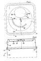
- Fig. 1 is a top plan view of a container lid for use in an embodiment of the invention;
- Fig. 2 is a vertical section elevation of a container including the lid shown in Fig. 1;
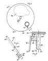
- Fig. 3 is a plan view of a closure member;
- Fig. 4 is a section on V-V in Fig. 3;
- Fig. 5 is an enlarged detail of Fig. 4, and also shows a locking pin;
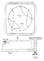
- Fig. 6 is a schematic top plan view of a modified embodiment of a container lid;
- Fig. 7 is a partly sectional view in elevation of the lid shown in Fig. 6;
- Fig. 8 is an axial section through a modified form of locking pin, with a detail of a modified form of lid;
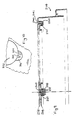
- Fig. 9 is a vertical section through a second embodiment of container lid; and
- Fig. 10 is a detail of a plan view of a container lid showing variant needle detachment formations.
- Referring first to Figs. 1 to 5, a container 10 (whose
body 12 is shown schematically in Fig. 2) has an upper wall member orlid 14 whose mouth has a downwardlyopen channel 16 with an inwardly directedbead 18 for snap-engaging a complementary formation at the top of the body 12 (not shown). The upper face of thelid 14 has a recessedcircular portion 20 penetrated by anaccess aperture 22. Theaperture 22 is approximately elliptical. It may include anarrow extension 24 projecting into aregion 26 where thelid 14 is of reduced thickness. Thisinlet 24 provides a means for detaching needles from hypodermic syringes. - The
recess 20 has anarcuate depression 28, which is of uniform depth except for adeep aperture 30 at the end nearest the opening 22. In the centre of therecess 20, there is anupstanding pillar 32 which has a projectingbead 34 adjacent its top. - Figs. 3 and 4 show an
obstructor member 38 in the form of a disc dimensioned to fit within therecess 20. The disc has a peripheralupturned lip 40 and a central upturnedwall portion 42 defining a bushing having acentral aperture 44. This is dimensioned so that thedisc 38 can fit into therecess 20, with thepillar 32 extending through theaperture 44. The disc is a push-fit, such that thebead 34 snap-engages above the bushing 42, to retain the disc rotatably on the lid. - The disc has a
large aperture 46 similar to the access opening 22 andthinned area 26 of the lid, with which it can be brought into register by rotation. The disc has ahandgrip 50 defined by a frustoconical wall withexternal serrations 52. As can be seen from Figs. 4 and 5, thewall 50 has an upper portion whose internal surface is formed with a vertically spaced pair ofannular recesses annular wall 56, leading to a centraltubular portion 58. Alocking pin 60 has ashank 62 dimensioned to be slidable within thetube 58 so that it can project beneath thetube 58 by variable amounts. Thepin 60 has ahead 64 including a radially outercurved bead portion 66. This is shaped and dimensioned so that it can locate in the upperannular groove 53. In this configuration, theshank 62 projects a short way beneath thetubular portion 58 and the rest of thedisc 38. The projecting end portion extends into thearcuate recess 28, and thus guides and delimits the rotation of the disc. When the disc is rotated so that itsmain aperture 46 is in register with the access opening 22, thepin 60 is at the right-hand end of thearcuate recess 28, as seen in Fig. 1. To close the access opening 22, thedisc 38 is rotated clockwise as far as it can go. Thus the pin moves to the other end of thearcuate recess 28, in the region of thedeep portion 30. If it is desired to lock the disc in the closing configuration, application of downward pressure to the locking pin enables it to travel downwardly, thebead 66 jumping from the upperannular recess 53 to thelower recess 54. Theshank 62 then extends into thedeep recess 30, and prevents rotation of the disc. - The container is suitably made of a plastics material, e.g. polypropylene. A full container may be incinerated intact, with its contents.
- The
obstructor disc 38 is secured to thelid 14 only by the engagement of thebead 34 of thecentral pillar 32 of the lid above thebushing 42. Figs. 6 and 7 show how thelid 114 may be modified to enhance the security of the connection. Theperipheral wall 115 delimiting thecircular recess 120 may have anannular bead 170 behind which thedisc 38 snap-engages. However, unless this is very slight, it makes it very difficult to produce lids by injection moulding and free them from the mould. Therefore, a plurality of radially projectingpips 172 are provided as well as (or instead of) thebead 170, for thedisc 38 to engage behind. This makes thedisc 38 very difficult to separate from the lid, particularly when access from behind is impossible, as it is when the lid is locked on a container. - Fig. 8 shows another way of strengthening the connection of the
disc 38 and the lid. This operates only when the locking pin is depressed to lock the disc in the closing configuration. It involves modifications to both the locking pin and the lid. The modified pin 160 has a shank with a tapered end portion 174 leading to an annular groove 176. To increase compressibility of the end portion, there may be an axial slot 178. In thelid 114, the locking end of thearcuate depression 28 provides a simple hole 180 through the thickness of the lid, rather than ablind aperture 30. The diameter of the hole is between the minimum and maximum diameters of the tapered end portion 174 of the pin. Thus when the pin is depressed for locking, its end portion is forced through the hole 180 (with compression or deformation), and the pin becomes locked to the lid because the lid margin around the hole engages in the annular groove 176. The pin thus clamps the disc to the lid. (There may be formations 52-58 on the disc substantially as shown in Fig. 5, though the snap-engagement of the pin's head 166 in a lowerannular recess 54 may not now be necessary.) - Fig. 9 shows another form of
container lid 214 andobstructor member 238. The latter again has the form of a disc with aperipheral lip 240, but this is down-turned and ends in aradially exrending flange 241. Thelid 214 has acircumferential channel 220 in which thelip 240 engages. The radially inner wall of thechannel 220 has acircumferentially extending projection 270 which serves as a clip beneath which theflange 241 engages. Thedisc 238 has a central downwardly-extendingbacking 242 with anenlarged head 243. Thelid 214 has acentral opening 232 delimited by adownturned lip 233 dimensioned so that thebushing 242 of thedisc 238 can be pushed into the aperture until thehead 243 is forced past thelip 233, beneath which it becomes trapped. This engagement and that of thelip 240 in thechannel 220 allow the disc to rotate but resist its withdrawal. - Fig. 10 shows a portion of a lid's
access aperture 322. Like theaperture 22 shown in Fig. 1, its margin includes a thinnedregion 326 into which a narrow inlet 324 opens, this inlet being slightly tapered and intended for use in disengaging a needle from a syringe. This variant includes an alternative inlet 325 whose width is reduced stepwise. This is to allow a syringe to be engaged therewith by rotation, whereafter it can be pulled free of its needle.
Claims (10)
whereupon the pin means is displaceable so that abutment with the step formation restrains displacement from the blocking to the open configuration.
Applications Claiming Priority (2)
| Application Number | Priority Date | Filing Date | Title |
|---|---|---|---|
| GB888823834A GB8823834D0 (en) | 1988-10-11 | 1988-10-11 | Closure for container |
| GB8823834 | 1988-10-11 |
Publications (2)
| Publication Number | Publication Date |
|---|---|
| EP0367422A1 true EP0367422A1 (en) | 1990-05-09 |
| EP0367422B1 EP0367422B1 (en) | 1994-12-21 |
Family
ID=10645031
Family Applications (1)
| Application Number | Title | Priority Date | Filing Date |
|---|---|---|---|
| EP89310334A Expired - Lifetime EP0367422B1 (en) | 1988-10-11 | 1989-10-11 | Closure for container |
Country Status (3)
| Country | Link |
|---|---|
| EP (1) | EP0367422B1 (en) |
| DE (1) | DE68920121T2 (en) |
| GB (1) | GB8823834D0 (en) |
Cited By (10)
| Publication number | Priority date | Publication date | Assignee | Title |
|---|---|---|---|---|
| EP0597063A1 (en) * | 1992-05-26 | 1994-05-18 | BUTLER, William F. | Method and apparatus for electrically destroying a syringe needle |
| EP0621048A1 (en) * | 1993-04-22 | 1994-10-26 | DISTRI CLUB MEDICAL, Société Anonyme: | Box for contaminated medical articles |
| EP0691279A2 (en) | 1994-07-04 | 1996-01-10 | Rexam Plastic Packaging Limited | Container for medical waste |
| WO1996025966A1 (en) * | 1995-02-21 | 1996-08-29 | Pharmacia & Upjohn Company | Locking package for a syringe |
| WO1998008560A1 (en) * | 1996-08-30 | 1998-03-05 | Sanypick, S.A. | Hermetically sealed container for clinical residues |
| EP0891785A3 (en) * | 1997-07-16 | 1999-03-31 | Heinz Rigling | Cannula container |
| WO2003006322A2 (en) * | 2001-07-11 | 2003-01-23 | Owen Mumford Limited | Sharps disposal container |
| EP1380316A1 (en) * | 2002-07-11 | 2004-01-14 | Rigling, Heinz | Collect and waste container, especially for cannulas |
| ES2296469A1 (en) * | 2005-10-14 | 2008-04-16 | Sistemas Integrales Sanitarios, S.A. | Closing cover for packaging containers of clinical or infectious remainders, has circumferential groove and orifice of entrance of remainders and over cover in form of spherical cap, which is fitted in groove |
| WO2014082861A1 (en) * | 2012-11-28 | 2014-06-05 | Corporació Sanitaria Parc Taulí | Sanitary waste container |
Citations (5)
| Publication number | Priority date | Publication date | Assignee | Title |
|---|---|---|---|---|
| US4375849A (en) * | 1981-05-15 | 1983-03-08 | Sage Products, Inc. | Syringe needle removal and disposal device |
| US4466538A (en) * | 1983-04-15 | 1984-08-21 | Biosafety Systems, Inc. | Hypodermic needle disposal system |
| US4657139A (en) * | 1985-09-30 | 1987-04-14 | Sage Products, Inc. | Closure for a syringe collection and disposal container |
| WO1988000067A1 (en) * | 1986-07-09 | 1988-01-14 | Anthony Lees | Containers |
| DE8808135U1 (en) * | 1988-06-24 | 1988-08-25 | Achterberg, Willem Jan, Veenendaal, Nl |
-
1988
- 1988-10-11 GB GB888823834A patent/GB8823834D0/en active Pending
-
1989
- 1989-10-11 DE DE68920121T patent/DE68920121T2/en not_active Expired - Fee Related
- 1989-10-11 EP EP89310334A patent/EP0367422B1/en not_active Expired - Lifetime
Patent Citations (5)
| Publication number | Priority date | Publication date | Assignee | Title |
|---|---|---|---|---|
| US4375849A (en) * | 1981-05-15 | 1983-03-08 | Sage Products, Inc. | Syringe needle removal and disposal device |
| US4466538A (en) * | 1983-04-15 | 1984-08-21 | Biosafety Systems, Inc. | Hypodermic needle disposal system |
| US4657139A (en) * | 1985-09-30 | 1987-04-14 | Sage Products, Inc. | Closure for a syringe collection and disposal container |
| WO1988000067A1 (en) * | 1986-07-09 | 1988-01-14 | Anthony Lees | Containers |
| DE8808135U1 (en) * | 1988-06-24 | 1988-08-25 | Achterberg, Willem Jan, Veenendaal, Nl |
Cited By (16)
| Publication number | Priority date | Publication date | Assignee | Title |
|---|---|---|---|---|
| EP0597063A1 (en) * | 1992-05-26 | 1994-05-18 | BUTLER, William F. | Method and apparatus for electrically destroying a syringe needle |
| EP0597063A4 (en) * | 1992-05-26 | 1994-12-07 | William F Butler | Method and apparatus for electrically destroying a syringe needle. |
| EP0621048A1 (en) * | 1993-04-22 | 1994-10-26 | DISTRI CLUB MEDICAL, Société Anonyme: | Box for contaminated medical articles |
| FR2704138A1 (en) * | 1993-04-22 | 1994-10-28 | Mcs | Box for contaminated medical objects. |
| AU701206B2 (en) * | 1994-07-04 | 1999-01-21 | Rexam Plastic Packaging Limited | Container for medical waste |
| EP0691279A2 (en) | 1994-07-04 | 1996-01-10 | Rexam Plastic Packaging Limited | Container for medical waste |
| WO1996025966A1 (en) * | 1995-02-21 | 1996-08-29 | Pharmacia & Upjohn Company | Locking package for a syringe |
| US5566828A (en) * | 1995-02-21 | 1996-10-22 | The Upjohn Company | Locking package for a syringe |
| WO1998008560A1 (en) * | 1996-08-30 | 1998-03-05 | Sanypick, S.A. | Hermetically sealed container for clinical residues |
| EP0891785A3 (en) * | 1997-07-16 | 1999-03-31 | Heinz Rigling | Cannula container |
| WO2003006322A2 (en) * | 2001-07-11 | 2003-01-23 | Owen Mumford Limited | Sharps disposal container |
| WO2003006322A3 (en) * | 2001-07-11 | 2003-05-01 | Owen Mumford Ltd | Sharps disposal container |
| US6971516B2 (en) | 2001-07-11 | 2005-12-06 | Owen Mumford Limited | Sharps containers |
| EP1380316A1 (en) * | 2002-07-11 | 2004-01-14 | Rigling, Heinz | Collect and waste container, especially for cannulas |
| ES2296469A1 (en) * | 2005-10-14 | 2008-04-16 | Sistemas Integrales Sanitarios, S.A. | Closing cover for packaging containers of clinical or infectious remainders, has circumferential groove and orifice of entrance of remainders and over cover in form of spherical cap, which is fitted in groove |
| WO2014082861A1 (en) * | 2012-11-28 | 2014-06-05 | Corporació Sanitaria Parc Taulí | Sanitary waste container |
Also Published As
| Publication number | Publication date |
|---|---|
| DE68920121T2 (en) | 1995-06-29 |
| GB8823834D0 (en) | 1988-11-16 |
| DE68920121D1 (en) | 1995-02-02 |
| EP0367422B1 (en) | 1994-12-21 |
Similar Documents
| Publication | Publication Date | Title |
|---|---|---|
| CA2254174C (en) | Single-use safety syringe | |
| US5242421A (en) | Needle cap | |
| EP3498214B1 (en) | Medical waste container hinged lid | |
| US4883471A (en) | Disposable shielded medical syringe | |
| US5304138A (en) | Single use, destructible medical syringe | |
| US7481797B2 (en) | Retractable needle single use safety syringe | |
| US6440104B1 (en) | Safety shield assembly | |
| AU2013260666B2 (en) | Automatic injection device with delay mechanism including dual functioning biasing member | |
| EP0998953A1 (en) | Improved safety syringe | |
| US5740909A (en) | Lockable and leak-proof sharps disposal container | |
| US6436086B1 (en) | Method of using a safety shield assembly and related combinations thereof | |
| EP0367422B1 (en) | Closure for container | |
| EP0997159A1 (en) | Method for making a safety shield assembly and related combination thereof | |
| MXPA97008658A (en) | Retractible syringe of proof of operations indebi | |
| EP1592346A2 (en) | Safety needle assembly | |
| CN103945787A (en) | Medical waste containers and lids therefore | |
| AU5561890A (en) | A syringe | |
| US6971516B2 (en) | Sharps containers | |
| US6379330B1 (en) | Container for a hypodermic syringe | |
| JP2966095B2 (en) | Retractable syringe | |
| JP3967408B2 (en) | Syringe safety needle | |
| EP1704888B1 (en) | Retractable needle single use safety syringe | |
| KR19980062429U (en) | Portable injection liquid injection device | |
| CN212261537U (en) | Flip type capacity control type medical sharp instrument box | |
| KR102213863B1 (en) | lock process motion device of preventing reuse tool for disposable syringe |
Legal Events
| Date | Code | Title | Description |
|---|---|---|---|
| PUAI | Public reference made under article 153(3) epc to a published international application that has entered the european phase |
Free format text: ORIGINAL CODE: 0009012 |
|
| AK | Designated contracting states |
Kind code of ref document: A1 Designated state(s): DE FR GB IT NL |
|
| 17P | Request for examination filed |
Effective date: 19901106 |
|
| 17Q | First examination report despatched |
Effective date: 19930429 |
|
| RAP1 | Party data changed (applicant data changed or rights of an application transferred) |
Owner name: DRG PLASTICS LIMITED |
|
| GRAA | (expected) grant |
Free format text: ORIGINAL CODE: 0009210 |
|
| AK | Designated contracting states |
Kind code of ref document: B1 Designated state(s): DE FR GB IT NL |
|
| REF | Corresponds to: |
Ref document number: 68920121 Country of ref document: DE Date of ref document: 19950202 |
|
| ET | Fr: translation filed | ||
| ITF | It: translation for a ep patent filed |
Owner name: MODIANO & ASSOCIATI S.R.L. |
|
| PLBE | No opposition filed within time limit |
Free format text: ORIGINAL CODE: 0009261 |
|
| STAA | Information on the status of an ep patent application or granted ep patent |
Free format text: STATUS: NO OPPOSITION FILED WITHIN TIME LIMIT |
|
| 26N | No opposition filed | ||
| NLT1 | Nl: modifications of names registered in virtue of documents presented to the patent office pursuant to art. 16 a, paragraph 1 |
Owner name: REXAM PLASTIC PACKAGING LIMITED |
|
| REG | Reference to a national code |
Ref country code: FR Ref legal event code: CD |
|
| ITPR | It: changes in ownership of a european patent |
Owner name: MUTAMENTO DI DENOMIN;REXAM PLASTIC. PACKAGING LIMI |
|
| REG | Reference to a national code |
Ref country code: GB Ref legal event code: 732E |
|
| NLS | Nl: assignments of ep-patents |
Owner name: REXAM MEDICAL PACKAGING LIMITED |
|
| REG | Reference to a national code |
Ref country code: FR Ref legal event code: TP |
|
| PGFP | Annual fee paid to national office [announced via postgrant information from national office to epo] |
Ref country code: DE Payment date: 20011024 Year of fee payment: 13 |
|
| PGFP | Annual fee paid to national office [announced via postgrant information from national office to epo] |
Ref country code: NL Payment date: 20011026 Year of fee payment: 13 |
|
| REG | Reference to a national code |
Ref country code: GB Ref legal event code: IF02 |
|
| PG25 | Lapsed in a contracting state [announced via postgrant information from national office to epo] |
Ref country code: DE Free format text: LAPSE BECAUSE OF NON-PAYMENT OF DUE FEES Effective date: 20030501 Ref country code: NL Free format text: LAPSE BECAUSE OF NON-PAYMENT OF DUE FEES Effective date: 20030501 |
|
| NLV4 | Nl: lapsed or anulled due to non-payment of the annual fee |
Effective date: 20030501 |
|
| PG25 | Lapsed in a contracting state [announced via postgrant information from national office to epo] |
Ref country code: IT Free format text: LAPSE BECAUSE OF NON-PAYMENT OF DUE FEES;WARNING: LAPSES OF ITALIAN PATENTS WITH EFFECTIVE DATE BEFORE 2007 MAY HAVE OCCURRED AT ANY TIME BEFORE 2007. THE CORRECT EFFECTIVE DATE MAY BE DIFFERENT FROM THE ONE RECORDED. Effective date: 20051011 |
|
| REG | Reference to a national code |
Ref country code: GB Ref legal event code: 732E |
|
| REG | Reference to a national code |
Ref country code: FR Ref legal event code: CD Ref country code: FR Ref legal event code: CA |
|
| REG | Reference to a national code |
Ref country code: FR Ref legal event code: TP |
|
| PGFP | Annual fee paid to national office [announced via postgrant information from national office to epo] |
Ref country code: FR Payment date: 20081023 Year of fee payment: 20 |
|
| PGFP | Annual fee paid to national office [announced via postgrant information from national office to epo] |
Ref country code: GB Payment date: 20081020 Year of fee payment: 20 |
|
| REG | Reference to a national code |
Ref country code: GB Ref legal event code: PE20 Expiry date: 20091010 |
|
| PG25 | Lapsed in a contracting state [announced via postgrant information from national office to epo] |
Ref country code: GB Free format text: LAPSE BECAUSE OF EXPIRATION OF PROTECTION Effective date: 20091010 |