EP0368713B1 - Stackable or nestable containers with removable closures - Google Patents
Stackable or nestable containers with removable closures Download PDFInfo
- Publication number
- EP0368713B1 EP0368713B1 EP89402932A EP89402932A EP0368713B1 EP 0368713 B1 EP0368713 B1 EP 0368713B1 EP 89402932 A EP89402932 A EP 89402932A EP 89402932 A EP89402932 A EP 89402932A EP 0368713 B1 EP0368713 B1 EP 0368713B1
- Authority
- EP
- European Patent Office
- Prior art keywords
- container
- flaps
- walls
- container according
- active position
- Prior art date
- Legal status (The legal status is an assumption and is not a legal conclusion. Google has not performed a legal analysis and makes no representation as to the accuracy of the status listed.)
- Expired - Lifetime
Links
Images


Classifications
-
- B—PERFORMING OPERATIONS; TRANSPORTING
- B65—CONVEYING; PACKING; STORING; HANDLING THIN OR FILAMENTARY MATERIAL
- B65D—CONTAINERS FOR STORAGE OR TRANSPORT OF ARTICLES OR MATERIALS, e.g. BAGS, BARRELS, BOTTLES, BOXES, CANS, CARTONS, CRATES, DRUMS, JARS, TANKS, HOPPERS, FORWARDING CONTAINERS; ACCESSORIES, CLOSURES, OR FITTINGS THEREFOR; PACKAGING ELEMENTS; PACKAGES
- B65D21/00—Nestable, stackable or joinable containers; Containers of variable capacity
- B65D21/02—Containers specially shaped, or provided with fittings or attachments, to facilitate nesting, stacking, or joining together
- B65D21/06—Containers specially shaped, or provided with fittings or attachments, to facilitate nesting, stacking, or joining together with movable parts adapted to be placed in alternative positions for nesting the containers when empty and for stacking them when full
- B65D21/062—Containers specially shaped, or provided with fittings or attachments, to facilitate nesting, stacking, or joining together with movable parts adapted to be placed in alternative positions for nesting the containers when empty and for stacking them when full the movable parts being attached or integral and displaceable into a position overlying the top of the container, e.g. bails, corner plates
-
- B—PERFORMING OPERATIONS; TRANSPORTING
- B65—CONVEYING; PACKING; STORING; HANDLING THIN OR FILAMENTARY MATERIAL
- B65D—CONTAINERS FOR STORAGE OR TRANSPORT OF ARTICLES OR MATERIALS, e.g. BAGS, BARRELS, BOTTLES, BOXES, CANS, CARTONS, CRATES, DRUMS, JARS, TANKS, HOPPERS, FORWARDING CONTAINERS; ACCESSORIES, CLOSURES, OR FITTINGS THEREFOR; PACKAGING ELEMENTS; PACKAGES
- B65D43/00—Lids or covers for rigid or semi-rigid containers
- B65D43/02—Removable lids or covers
- B65D43/0202—Removable lids or covers without integral tamper element
- B65D43/0204—Removable lids or covers without integral tamper element secured by snapping over beads or projections
- B65D43/0212—Removable lids or covers without integral tamper element secured by snapping over beads or projections only on the outside, or a part turned to the outside, of the mouth
-
- B—PERFORMING OPERATIONS; TRANSPORTING
- B65—CONVEYING; PACKING; STORING; HANDLING THIN OR FILAMENTARY MATERIAL
- B65D—CONTAINERS FOR STORAGE OR TRANSPORT OF ARTICLES OR MATERIALS, e.g. BAGS, BARRELS, BOTTLES, BOXES, CANS, CARTONS, CRATES, DRUMS, JARS, TANKS, HOPPERS, FORWARDING CONTAINERS; ACCESSORIES, CLOSURES, OR FITTINGS THEREFOR; PACKAGING ELEMENTS; PACKAGES
- B65D2543/00—Lids or covers essentially for box-like containers
- B65D2543/00009—Details of lids or covers for rigid or semi-rigid containers
- B65D2543/00018—Overall construction of the lid
- B65D2543/00064—Shape of the outer periphery
- B65D2543/0012—Shape of the outer periphery having straight sides, e.g. with curved corners
- B65D2543/00175—Shape of the outer periphery having straight sides, e.g. with curved corners four straight sides, e.g. trapezium or diamond
- B65D2543/00194—Shape of the outer periphery having straight sides, e.g. with curved corners four straight sides, e.g. trapezium or diamond square or rectangular
-
- B—PERFORMING OPERATIONS; TRANSPORTING
- B65—CONVEYING; PACKING; STORING; HANDLING THIN OR FILAMENTARY MATERIAL
- B65D—CONTAINERS FOR STORAGE OR TRANSPORT OF ARTICLES OR MATERIALS, e.g. BAGS, BARRELS, BOTTLES, BOXES, CANS, CARTONS, CRATES, DRUMS, JARS, TANKS, HOPPERS, FORWARDING CONTAINERS; ACCESSORIES, CLOSURES, OR FITTINGS THEREFOR; PACKAGING ELEMENTS; PACKAGES
- B65D2543/00—Lids or covers essentially for box-like containers
- B65D2543/00009—Details of lids or covers for rigid or semi-rigid containers
- B65D2543/00018—Overall construction of the lid
- B65D2543/00259—Materials used
- B65D2543/00296—Plastic
-
- B—PERFORMING OPERATIONS; TRANSPORTING
- B65—CONVEYING; PACKING; STORING; HANDLING THIN OR FILAMENTARY MATERIAL
- B65D—CONTAINERS FOR STORAGE OR TRANSPORT OF ARTICLES OR MATERIALS, e.g. BAGS, BARRELS, BOTTLES, BOXES, CANS, CARTONS, CRATES, DRUMS, JARS, TANKS, HOPPERS, FORWARDING CONTAINERS; ACCESSORIES, CLOSURES, OR FITTINGS THEREFOR; PACKAGING ELEMENTS; PACKAGES
- B65D2543/00—Lids or covers essentially for box-like containers
- B65D2543/00009—Details of lids or covers for rigid or semi-rigid containers
- B65D2543/00342—Central part of the lid
- B65D2543/00398—Reinforcing ribs in the central part of the closure
- B65D2543/00407—Reinforcing ribs in the central part of the closure radial
-
- B—PERFORMING OPERATIONS; TRANSPORTING
- B65—CONVEYING; PACKING; STORING; HANDLING THIN OR FILAMENTARY MATERIAL
- B65D—CONTAINERS FOR STORAGE OR TRANSPORT OF ARTICLES OR MATERIALS, e.g. BAGS, BARRELS, BOTTLES, BOXES, CANS, CARTONS, CRATES, DRUMS, JARS, TANKS, HOPPERS, FORWARDING CONTAINERS; ACCESSORIES, CLOSURES, OR FITTINGS THEREFOR; PACKAGING ELEMENTS; PACKAGES
- B65D2543/00—Lids or covers essentially for box-like containers
- B65D2543/00009—Details of lids or covers for rigid or semi-rigid containers
- B65D2543/00444—Contact between the container and the lid
- B65D2543/00481—Contact between the container and the lid on the inside or the outside of the container
- B65D2543/0049—Contact between the container and the lid on the inside or the outside of the container on the inside, or a part turned to the inside of the mouth of the container
- B65D2543/00527—NO contact
-
- B—PERFORMING OPERATIONS; TRANSPORTING
- B65—CONVEYING; PACKING; STORING; HANDLING THIN OR FILAMENTARY MATERIAL
- B65D—CONTAINERS FOR STORAGE OR TRANSPORT OF ARTICLES OR MATERIALS, e.g. BAGS, BARRELS, BOTTLES, BOXES, CANS, CARTONS, CRATES, DRUMS, JARS, TANKS, HOPPERS, FORWARDING CONTAINERS; ACCESSORIES, CLOSURES, OR FITTINGS THEREFOR; PACKAGING ELEMENTS; PACKAGES
- B65D2543/00—Lids or covers essentially for box-like containers
- B65D2543/00009—Details of lids or covers for rigid or semi-rigid containers
- B65D2543/00444—Contact between the container and the lid
- B65D2543/00481—Contact between the container and the lid on the inside or the outside of the container
- B65D2543/00537—Contact between the container and the lid on the inside or the outside of the container on the outside, or a part turned to the outside of the mouth of the container
-
- B—PERFORMING OPERATIONS; TRANSPORTING
- B65—CONVEYING; PACKING; STORING; HANDLING THIN OR FILAMENTARY MATERIAL
- B65D—CONTAINERS FOR STORAGE OR TRANSPORT OF ARTICLES OR MATERIALS, e.g. BAGS, BARRELS, BOTTLES, BOXES, CANS, CARTONS, CRATES, DRUMS, JARS, TANKS, HOPPERS, FORWARDING CONTAINERS; ACCESSORIES, CLOSURES, OR FITTINGS THEREFOR; PACKAGING ELEMENTS; PACKAGES
- B65D2543/00—Lids or covers essentially for box-like containers
- B65D2543/00009—Details of lids or covers for rigid or semi-rigid containers
- B65D2543/00444—Contact between the container and the lid
- B65D2543/00592—Snapping means
- B65D2543/00601—Snapping means on the container
- B65D2543/00611—Profiles
- B65D2543/00648—Flange or lip
-
- B—PERFORMING OPERATIONS; TRANSPORTING
- B65—CONVEYING; PACKING; STORING; HANDLING THIN OR FILAMENTARY MATERIAL
- B65D—CONTAINERS FOR STORAGE OR TRANSPORT OF ARTICLES OR MATERIALS, e.g. BAGS, BARRELS, BOTTLES, BOXES, CANS, CARTONS, CRATES, DRUMS, JARS, TANKS, HOPPERS, FORWARDING CONTAINERS; ACCESSORIES, CLOSURES, OR FITTINGS THEREFOR; PACKAGING ELEMENTS; PACKAGES
- B65D2543/00—Lids or covers essentially for box-like containers
- B65D2543/00009—Details of lids or covers for rigid or semi-rigid containers
- B65D2543/00444—Contact between the container and the lid
- B65D2543/00592—Snapping means
- B65D2543/00601—Snapping means on the container
- B65D2543/00675—Periphery concerned
- B65D2543/00694—Segments
-
- B—PERFORMING OPERATIONS; TRANSPORTING
- B65—CONVEYING; PACKING; STORING; HANDLING THIN OR FILAMENTARY MATERIAL
- B65D—CONTAINERS FOR STORAGE OR TRANSPORT OF ARTICLES OR MATERIALS, e.g. BAGS, BARRELS, BOTTLES, BOXES, CANS, CARTONS, CRATES, DRUMS, JARS, TANKS, HOPPERS, FORWARDING CONTAINERS; ACCESSORIES, CLOSURES, OR FITTINGS THEREFOR; PACKAGING ELEMENTS; PACKAGES
- B65D2543/00—Lids or covers essentially for box-like containers
- B65D2543/00009—Details of lids or covers for rigid or semi-rigid containers
- B65D2543/00444—Contact between the container and the lid
- B65D2543/00592—Snapping means
- B65D2543/00712—Snapping means on the lid
- B65D2543/00722—Profiles
- B65D2543/00759—Flange or lip
-
- B—PERFORMING OPERATIONS; TRANSPORTING
- B65—CONVEYING; PACKING; STORING; HANDLING THIN OR FILAMENTARY MATERIAL
- B65D—CONTAINERS FOR STORAGE OR TRANSPORT OF ARTICLES OR MATERIALS, e.g. BAGS, BARRELS, BOTTLES, BOXES, CANS, CARTONS, CRATES, DRUMS, JARS, TANKS, HOPPERS, FORWARDING CONTAINERS; ACCESSORIES, CLOSURES, OR FITTINGS THEREFOR; PACKAGING ELEMENTS; PACKAGES
- B65D2543/00—Lids or covers essentially for box-like containers
- B65D2543/00009—Details of lids or covers for rigid or semi-rigid containers
- B65D2543/00444—Contact between the container and the lid
- B65D2543/00592—Snapping means
- B65D2543/00712—Snapping means on the lid
- B65D2543/00787—Periphery concerned
- B65D2543/00805—Segments
Definitions
- the invention relates to handling bins, in particular made of plastic, which can be stacked one on top of the other or partially nested one inside the other.
- the subject of the invention is a container comprising a bottom from which side walls rise, the free end of which defines an opening which can be closed by a cover fitted to the container, the latter comprising retractable flaps mounted in articulation in rotation on along the free end of two opposite side walls, between a first active stable position in which the flaps are folded over the opening of the container and are capable of receiving an overlying container on them, and a second non-active position , in which these same flaps extend outside the tank, then authorizing the nesting of the tanks in one another.
- the invention proposes a container of the aforementioned type which is characterized in that the cover which it can be provided with, comprises, along the edge of one of its sides, and for its connection to the tank, hook-shaped engagement means capable of being received under a rim which the container has at its periphery, towards the free end of its side walls, and this both in the active position and in the non-active position of the flaps.
- the cover can be placed on the tray regardless of the position of the flaps and therefore regardless of the state in which the tray is located (stacking or nesting position).
- An advantage of the container of the invention is, moreover, that its flaps and its cover can be accommodated in the overall size of the container, thus greatly facilitating storage problems.
- the flaps with which the container is equipped will preferably be curved at their lateral ends, the walls of the container then having grooves suitable for receiving these curved parts of the flaps when the latter are folded over the container.
- the flaps be provided with stable support in the active position, but, in addition, the walls of the container which are devoid of flaps will be prevented from moving away from one another (in particular when several loaded containers are stacked ), said curved parts playing the role of retaining elements once engaged in their receiving grooves.
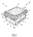
- a handling tank 1 of substantially parallelepiped shape with rectangular section made of plastic.
- the tank 1 which is open at its upper part comprises a bottom 2 assumed to be horizontal from which rise four side walls (of which only two marked 3, 4 are visible in the figure), which walls are slightly inclined relative to the vertical so to go by getting closer to each other towards the bottom 2.
- the container Towards the free upper part of its side walls, the container is reinforced on its outer face by a projecting peripheral belt 7 which is limited by a lower horizontal rib 8 and an upper horizontal rib 9, the latter forming the upper rim of the container on which can come to rest a removable cover 10 suitable for completely closing the opening of the tank, without however exceeding the overall size of the latter.
- the container is here equipped with retractable flaps 11 mounted articulated in rotation along the free upper end of two opposite side walls (in this case the two shorter walls 4 and 6).
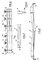
- the flaps 11 can occupy two extreme positions of stable equilibrium: a first position ( Figure 3) called active, in which the flaps are folded over the opening of the tray and are then suitable for receive on them an overlying tray, and a second position ( Figure 2) called non-active, in which these same flaps extend to the outside of the tank, substantially parallel to the walls 4 and 6 which carry them, then authorizing the nesting of the tanks one inside the other.
- the flaps 11 will preferably be shaped to come, in their inactive position of FIG. 2, to be housed along the corresponding walls of the tank, inside its belt 7, between the upper edge 9 and the lower rib. 8. Thus, they will in no way extend beyond the overall dimensions of the tank, thus avoiding any risk of damage.
- the shutter shown comprises pins 12 which extend parallel to the axis 20 of articulation of the shutter and protrude on either side of a series of branches 13, except as regards the two innermost branches where only one nipple has been provided, directed towards the outside of the flap. Between the branches 13 are provided notches 15 whose role will appear below.
- passages 14 in the upper rim 9 of the corresponding walls of the tank are introduced the pins 12, which then play, as we have understood, the role of articulation shaft.
- the passages 14 could be opened downwards at 16 (FIG. 3), a flat 12a (FIG. 6) being able to be formed along the length of the nipples so that the latter do not unexpectedly disengage from their receiving passages after being introduced there.
- Figure 7 to see illustrated half of the shutter shown in Figure 6 (the other half being identical to that which has been shown).
- this figure 7 we wanted to clearly highlight the shape of the lateral ends 11a of the flaps which are bent into hooks 17, which are, in the active position of the flaps, received in grooves 18 arranged facing towards the upper part of the walls 3 and 5 of the tank which are adjacent to those 4 and 6 along which the flaps are arranged.
- these flaps can come into their active position to bear on the edge of the grooves, the hooks 17 preventing excessive deformation on the walls which can come from an additional load when several trays are stacked.
- this cover comprises along one of its shorter side edges, sections 21 of wall shaped clean hook to engage under the rim 9 of a corresponding side wall (4 or 6) of the container, this engagement being able to be carried out, that the flaps 11 are in the active position (FIG. 3, position in which the flaps are still housed in the overall dimensions of the container, therefore in no way harming when fitting the cover) or in the inactive position ( Figure 2).
- the sections 21 of the cover then engage through the notches 15 of the flaps.
- cover on its edge opposite to that where its engagement means are shaped, it may have only a single fallen edge 22, while projecting ribs 23 may be shaped near the longer edges of the cover, on the side of its face to be directed towards the container, so that these ribs 23 extend towards the interior of the container once the cover is in position, thus limiting its lateral displacement and stiffening it .
- the cover 10 On its face which must be directed towards the outside of the tank, the cover 10 may also have, near its periphery, a rib 24 in the form of a frame, intended to limit the movement of the trays when these fitted with their cover must be stacked on top of each other (see also Figure 5).
- cutouts 25 may be provided locally in the rib 24.
- wall 3 of FIG. 1 it comprises on the outer face of this wall and in the lower part, a recess or a notch 26 suitable for receiving a label (not shown).
- the opening to the outside is partially closed by a plate 27 intended to maintain the label in position, once it has been slid between the bottom of the notch and the retaining plate .
- the tank 1 may also include zones 28 formed slightly recessed in the thickness of its wall. In practice, these zones will be intended to receive retroreflective marking strips, useful in particular for ensuring automatic routing of the trays in the event that they are installed on conveyor belts, for example in the context of line work. It is moreover to ensure that the rollers have good attack from the rollers that short walls 29 slightly inclined with respect to the bottom have been provided at the connection between this same bottom and each of the side walls of the tank.
- the last container may also have orifices 30 (FIG. 5) in which short signaling or indexing lugs can be received marked 31 in Figure 9.
- the pins 31 will provided with a foot 31a of lesser thickness.
- FIGs 1 and 2 there is shown the tray with twice two tabs 32 formed on the two sides 4, 6 of the tray of shorter length and which in this case extend substantially perpendicular to the rib 8 which carry them, in direction of the bottom 2. Laterally, these tabs 32 will preferably extend until their ends 32a closest to the external angles of the container come into alignment with the side walls of the container adjacent to those where the tabs are formed ( Figures 1 and 4). This will in particular allow the tray to rest by its ribs 8 without tabs on supports such as rollers, angles, etc.
Abstract
Description
L'invention se rapporte à des bacs de manutention, notamment en matière plastique, pouvant être à volonté empilés les uns sur les autres ou emboîtés partiellement les uns dans les autres.The invention relates to handling bins, in particular made of plastic, which can be stacked one on top of the other or partially nested one inside the other.
Plus précisément l'invention a pour objet un bac comprenant un fond duquel s'élèvent des parois latérales dont l'extrémité libre définit une ouverture qui peut être fermée par un couvercle équipant le bac, ce dernier comprenant des volets escamotables montés articulés en rotation le long de l'extrémité libre de deux parois latérales opposées, entre une première position stable active dans laquelle les volets sont rabattus par dessus l'ouverture du bac et sont propres à recevoir en appui sur eux un bac surjacent, et une seconde position non active, dans laquelle ces mêmes volets s'étendent à l'extérieur du bac, autorisant alors l'emboîtement des bacs les uns dans les autres.More specifically, the subject of the invention is a container comprising a bottom from which side walls rise, the free end of which defines an opening which can be closed by a cover fitted to the container, the latter comprising retractable flaps mounted in articulation in rotation on along the free end of two opposite side walls, between a first active stable position in which the flaps are folded over the opening of the container and are capable of receiving an overlying container on them, and a second non-active position , in which these same flaps extend outside the tank, then authorizing the nesting of the tanks in one another.
Un tel bac est décrit dans la publication DE-A-3 521 894.Such a bin is described in publication DE-A-3,521,894.
Ceci étant, il est certains domaines (tels que celui du travail "à la chaine")dans lesquels il est apparu nécessaire que les utilisateurs de bacs puissent empiler ces derniers, que ceux-ci soient ou non équipés de leur couvercle, et quel que soit leur état (prêts à être empilés ou emboîtés), ceci de façon notamment à éviter que les personnes chargées des opérations de remplissage ou de manutention (ouverture, fermeture, transport, stockage des bacs...) aient, avant d'agir, à vérifier l'état dans lequel se trouve les bacs.This being the case, there are certain fields (such as that of "chain" work) in which it has appeared necessary for users of trays to be able to stack them, whether or not these are fitted with their lid, and whatever either their state (ready to be stacked or nested), this in particular in order to avoid that the persons responsible for filling or handling operations (opening, closing, transport, storage of containers, etc.) have, before acting, to check the state in which the bins are located.
Or, parmi les bacs existants, aucun n'a donné entière satisfaction aux utilisateurs confrontés à ce genre d'exigence.However, among the existing bins, none has given complete satisfaction to users faced with this kind of requirement.
C'est donc afin de résoudre les problèmes posés que l'invention propose un bac du type précité qui se caractérisé en ce que le couvercle dont il peut être pourvu, comprend, le long du bord de l'un de ses côtés, et pour sa liaison au bac, des moyens d'engagement en forme de crochet susceptibles d'être reçus sous un rebord que le bac présente à sa périphérie, vers l'extrémité libre de ses parois latérales, et ceci tant en position active qu'en position non active des volets.It is therefore in order to solve the problems posed that the invention proposes a container of the aforementioned type which is characterized in that the cover which it can be provided with, comprises, along the edge of one of its sides, and for its connection to the tank, hook-shaped engagement means capable of being received under a rim which the container has at its periphery, towards the free end of its side walls, and this both in the active position and in the non-active position of the flaps.
Ainsi, le couvercle pourra être mis en place sur le bac quelle que soit la position des volets et donc quel que soit l'état dans lequel se trouve le bac (position d'empilement ou d'emboîtement).Thus, the cover can be placed on the tray regardless of the position of the flaps and therefore regardless of the state in which the tray is located (stacking or nesting position).
Un avantage que présente le bac de l'invention est, en outre, que ses volets et son couvercle peuvent venir se loger dans l'encombrement hors tout du bac, facilitant ainsi grandement les problèmes de stockage.An advantage of the container of the invention is, moreover, that its flaps and its cover can be accommodated in the overall size of the container, thus greatly facilitating storage problems.
On notera également que selon l'invention les volets dont le bac est équipé seront de préférence recourbés à leurs extrémités latérales, les parois du bac comportant alors des rainures propres à recevoir ces parties recourbées des volets lorsque ces derniers sont rabattus sur le bac.It will also be noted that according to the invention the flaps with which the container is equipped will preferably be curved at their lateral ends, the walls of the container then having grooves suitable for receiving these curved parts of the flaps when the latter are folded over the container.
Ainsi, non seulement on assurera aux volets un appui stable en position active, mais, en outre, on évitera aux parois du bac qui sont dépourvues de volets de s'écarter l'une de l'autre (notamment lorsque plusieurs bacs chargés sont empilés), lesdites parties recourbées jouant le rôle d'éléments de retenue une fois engagées dans leurs rainures de réception.Thus, not only will the flaps be provided with stable support in the active position, but, in addition, the walls of the container which are devoid of flaps will be prevented from moving away from one another (in particular when several loaded containers are stacked ), said curved parts playing the role of retaining elements once engaged in their receiving grooves.
L'invention apparaîtra plus clairement de la description qui va suivre faite en référence aux dessins annexés donnés uniquement à titre d'exemple et dans lesquels :
- la figure 1 est une vue générale en perspective du bac de l'invention avec ses volets en position inactive (seul l'un des volets est visible), le bac étant ici équipé de son couvercle ;
- la figure 2 est pour moitié une vue de côté dans le sens de la
flèche 11 de la figure 1, et pour moitié une vue en coupe dans le plan II-II de la figure 4, les volets étant en position non active ; - la figure 3 est une vue identique à celle de la figure 2, hormis en ce qui concerne les volets qui sont ici représentés dans leur position active ;
- la figure 4 est une vue pour moitié de côté dans le sens de la flèche IV de la figure 1 et pour moitié en coupe dans le plan IV-IV de la figure 2. On notera que le bac a été ici représenté sans couvercle ;
- la figure 5 est une vue partielle de dessus du bac dans le sens de la flèche V de la figure 4, pour moitié avec couvercle (à gauche) pour moitié sans (à droite) ;
- la figure 6 est une vue de l'un des volets du bac, pour moitié en vue de dessus (à gauche) et pour moitié en vue de dessous (à droite) ;
- la figure 7 est une demi vue de côté du volet de la figure 6 dans le sens de la flèche VII ;
- la figure 8 est une vue pour moitié en coupe médiane et pour moitié en vue extérieure du couvercle dont peut être équipé le bac de l'invention,
- et la figure 9 est une représentation d'un ergot d'indexation, en vue de face.
- Figure 1 is a general perspective view of the container of the invention with its flaps in the inactive position (only one of the flaps is visible), the container being here equipped with its cover;
- Figure 2 is half a side view in the direction of the
arrow 11 in Figure 1, and half a sectional view in the plane II-II of Figure 4, the flaps being in the inactive position; - Figure 3 is a view identical to that of the Figure 2, except for the flaps which are shown here in their active position;
- Figure 4 is a half side view in the direction of arrow IV in Figure 1 and half in section in the plane IV-IV of Figure 2. Note that the tray has been shown here without cover;
- Figure 5 is a partial top view of the tray in the direction of arrow V in Figure 4, half with cover (left) for half without (right);
- Figure 6 is a view of one of the pan flaps, half in top view (left) and half in bottom view (right);
- Figure 7 is a half side view of the shutter of Figure 6 in the direction of arrow VII;
- Figure 8 is a view in half in section middle and half in external view of the cover with which the container of the invention can be fitted,
- and Figure 9 is a representation of an indexing lug, in front view.
Si l'on se reporte aux figures et notamment à la figure 1, on voit donc illustré un bac 1 de manutention de forme sensiblement parallélépipédique à section rectangulaire réalisé en matière plastique. Le bac 1 qui est ouvert à sa partie supérieure comprend un fond 2 supposé horizontal duquel s'élèvent quatre parois latérales (dont deux seulement repérées 3, 4 sont visibles sur la figure), lesquelles parois sont légèrement inclinées par rapport à la verticale de façon à aller en se rapprochant les unes vers les autres en direction du fond 2.If we refer to the figures and in particular to Figure 1, we therefore see illustrated a
Vers la partie supérieure libre de ses parois latérales, le bac est renforcé sur sa face extérieure par une ceinture périphérique 7 saillante qui est limitée par une nervure horizontale inférieure 8 et une nervure horizontale supérieure 9, cette dernière formant le rebord supérieur du bac sur lequel peut venir reposer un couvercle 10 amovible propre à obturer entièrement l'ouverture du bac, sans pour autant déborder de l'encombrement hors tout de ce dernier.Towards the free upper part of its side walls, the container is reinforced on its outer face by a projecting
Avant de s'intéresser au mode d'engagement du couvercle sur le bac, on notera tout d'abord que selon une caractéristique importante de l'invention, le bac est ici équipé de volets 11 escamotables montés articulés en rotation le long de l'extrémité supérieure libre de deux parois latérales opposées (en l'espèce les deux parois de plus petite longueur 4 et 6).Before considering the method of engagement of the cover on the container, it should first of all be noted that, according to an important characteristic of the invention, the container is here equipped with
Comme illustré clairement aux figures 2 et 3, les volets 11 peuvent occuper deux positions extrêmes d'équilibre stable : une première position (figure 3) dite active, dans laquelle les volets sont rabattus par dessus l'ouverture du bac et sont alors propres à recevoir en appui sur eux un bac surjacent, et une seconde position (figure 2) dite non active, dans laquelle ces mêmes volets s'étendent à l'extérieur du bac, sensiblement parallèlement aux parois 4 et 6 qui les portent, autorisant alors l'emboîtement des bacs les uns dans les autres.As clearly illustrated in Figures 2 and 3, the
En pratique, les volets 11 seront de préférence conformés pour venir, dans leur position inactive de la figure 2, se loger le long des parois correspondantes du bac, à l'intérieur de sa ceinture 7, entre le rebord supérieur 9 et la nervure inférieure 8. Ainsi, ils ne déborderont aucunement de l'encombrement hors tout du bac, évitant donc tout risque d'endommagement.In practice, the
Reportons-nous maintenant aux figures 6 et 7 pour voir illustrer un exemple de réalisation d'un volet 11 conforme à l'invention.Now refer to Figures 6 and 7 to see illustrate an embodiment of a
Le volet représenté comporte des tétons 12 qui s'étendent parallèlement à l'axe 20 d'articulation du volet et font saillie de part et d'autre d'une série de branches 13, hormis en ce qui concerne les deux branches les plus intérieures où l'on n'a prévu qu'un seul téton dirigé vers l'extérieur du volet. Entre les branches 13 sont ménagées des échancrures 15 dont le rôle apparaîtra ci-après.The shutter shown comprises
Pour permettre l'articulation en rotation des volets sur le bac, on a ménagé, comme on le voit figure 4, des passages 14 dans le rebord supérieur 9 des parois correspondantes du bac . Dans ces passages sont introduits les tétons 12, lesquels jouent alors, comme on l'a compris, le rôle d'arbre d'articulation.To allow the articulation in rotation of the flaps on the tank, there have been provided, as can be seen in FIG. 4,
Pour favoriser l'engagement des tétons, les passages 14 pourront être ouverts vers le bas en 16 (figure 3), un méplat 12a (figure 6) pouvant être formé sur la longueur des tétons pour que ces derniers ne se dégagent pas inopinément de leurs passages de réception après y avoir été introduits.To promote the engagement of the nipples, the
Reportons-nous maintenant à la figure 7 pour voir illustrée la moitié du volet représentée sur la figure 6 (l'autre moitié étant identique à celle qui a été figurée). Par cette figure 7 on a voulu mettre clairement en évidence la conformation des extrémités latérales 11a des volets qui sont recourbées en crochets 17, lesquels sont, en position active des volets, reçus dans des rainures 18 ménagées en regard vers la partie supérieure des parois 3 et 5 du bac qui sont adjacentes à celles 4 et 6 le long desquelles sont disposés les volets.Now refer to Figure 7 to see illustrated half of the shutter shown in Figure 6 (the other half being identical to that which has been shown). By this figure 7 we wanted to clearly highlight the shape of the
Ainsi, ces volets pourront venir dans leur position active prendre appui sur le rebord des rainures, les crochets 17 évitant aux parois toute déformation excessive pouvant provenir d'un surcroît de charge lorsque plusieurs bacs sont empilés.Thus, these flaps can come into their active position to bear on the edge of the grooves, the
Intéressons-nous maintenant plus précisément au couvercle 10 dont peut être équipé le bac de l'invention.Let us now focus more specifically on the
Figure 8, on remarquera tout d'abord que ce couvercle comprend le long de l'un de ses bords de côté de plus petite longueur, des tronçons 21 de paroi conformés en crochet propre à venir s'engager sous le rebord 9 d'une paroi latérale correspondante (4 ou 6) du bac, cet engagement pouvant être réalisé, que les volets 11 soient en position active (figure 3, position dans laquelle les volets sont encore logés dans l'encombrement hors tout du bac, ne nuisant donc aucunement à la mise en place du couvercle) ou en position inactive (figure 2). Dans ce dernier cas, on notera que les tronçons 21 du couvercle s'engagent alors à travers les échancrures 15 des volets.Figure 8, it will first be noted that this cover comprises along one of its shorter side edges,
En ce qui concerne le couvercle, on notera encore que sur sa bordure opposée à celle où sont conformés ses moyens d'engagement, il pourra ne présenter qu'un simple bord tombé 22, tandis que des nervures saillantes 23 pourront être conformées à proximité des bords de plus grande longueur du couvercle, du côté de sa face devant être dirigée vers le bac, de façon que ces nervures 23 s'étendent vers l'intérieur du bac une fois le couvercle en position, limitant ainsi son déplacement latéral et le rigidifiant.With regard to the cover, it will also be noted that on its edge opposite to that where its engagement means are shaped, it may have only a single
Sur sa face devant être dirigée vers l'extérieur du bac, le couvercle 10 pourra encore présenter, à proximité de sa périphérie une nervure 24 en forme de cadre, destinée à limiter le déplacement des bacs lorsque ceux-ci équipés de leur couvercle doivent être empilés les uns sur les autres (voir également figure 5).On its face which must be directed towards the outside of the tank, the
Pour permettre le passage d'une bande de fermeture tel qu'un feuillard plastique, des découpes 25 pourront être prévues localement dans la nervure 24.To allow the passage of a closure strip such as a plastic strip,
Si l'on s'intéresse à nouveau au bac de de l'invention en tant que tel, on notera que le long de l'une au moins de ses parois de plus grande longueur) telle que la paroi 3 de la figure 1) il comprend sur la face extérieure de cette paroi et en partie inférieure, un décrochement ou une échancrure 26 propre à recevoir une étiquette (non représentée).If we are again interested in the container of the invention as such, it will be noted that along at least one of its walls of greater length) such as
Comme illustré, l'ouverture sur l'extérieur est partiellement obturée par une plaque 27 destinée à assurer le maintien en position de l'étiquette, une fois que celle-ci a été glissée entre le fond de l'échancrure et la plaque de retenue.As illustrated, the opening to the outside is partially closed by a
Sous sa ceinture 7 et par exemple sur la face extérieure de l'une au moins de ses parois de plus grande longueur (telle que la paroi 5 de la figure 2), le bac 1 peut encore comporter des zones 28 formées légèrement en retrait dans l'épaisseur de sa paroi. En pratique ces zones seront destinées à recevoir des bandes rétroréfléchissantes de repérage, utiles notamment pour assurer un cheminement automatique des bacs dans le cas où ceux-ci seront installés sur des tapis convoyeurs, par exemple dans le cadre d'un travail à la chaîne. C'est d'ailleurs pour assurer au bac une bonne attaque des rouleaux que de courtes parois 29 légèrement inclinées par rapport au fond ont été prévues au niveau du raccordement entre ce même fond et chacune des parois latérales du bac.Under its
Dans son rebord supérieur 9, par exemple le long de l'une 5 de ses parois de plus grande longueur, le dernier bac pourra également comporter des orifices 30 (figure 5) dans lesquels pourront être reçus de courts ergots de signalisation ou d'indexation repérés 31 sur la figure 9. Pour s'engager dans les orifices 30, les ergots 31 seront munis d'un pied 31a de moindre épaisseur.In its
Sur les tapis convoyeurs, il est apparu que dans certains cas les bacs pouvaient avoir tendance à se chevaucher.On conveyor belts, it has become apparent that in some cases the tanks may have a tendency to overlap.
C'est afin d'éviter ces problèmes de chevauchement, que l'on a prévu de prolonger localement et vers le bas la nervure 8 qui limite en partie inférieure la ceinture 7 du bac.It is in order to avoid these overlapping problems, that provision has been made to extend locally and downward the
Figures 1 et 2, on a représenté le bac avec deux fois deux languettes 32 formées sur les deux côtés 4, 6 du bac de plus petite longueur et qui en l'espèce s'étendent sensiblement perpendiculairement à la nervure 8 qui les portent, en direction du fond 2. Latéralement, ces languettes 32 s'étendront de préférence jusqu'à ce que leurs extrémités 32a les plus proches des angles extérieurs du bac viennent dans l'alignement des parois latérales du bac adjacentes à celles où sont formées les languettes (figures 1 et 4). Cela permettra notamment de faire reposer le bac par ses nervures 8 dépourvues de languette sur des supports tels que galets, cornières, etc...Figures 1 and 2, there is shown the tray with twice two
Claims (10)
- Handling container comprising a base (2) of which the side walls (3, 4, 5, 6) are raised, and of which the free end forms an opening which can be closed by a lid (10) fitted onto the container, which container comprises retractable flaps (11) mounted so as to be rotatably hinged along the free end of two opposite side walls (4, 6) between a first, stable, active position in which the flaps are folded back above the opening of the container and can receive a container resting on top thereof, and a second, non-active position in which these flaps extend outside the container, thus allowing the containers to be fitted inside one another, characterised in that along the edge of one of its sides, and for connection thereof to the container, the said lid (10) comprises hook-shaped engaging means (21) which can be accommodated under an edge (9) disposed on the periphery of the container, towards the free end of the side walls thereof, both in the active and the non-active position of the flaps (11).
- Container according to claim 1 characterised in that in the non-active position of the flaps, the hooks (21) of the lid engage under the edge (9) of the container, through grooves (15) provided along the length of the said flaps.
- Container according to either of claims 1 or 2, of the type in which the side walls are inclined,in such a manner that they approach one another towards the base, characterised in that the lid (10) comprises a square-shaped rib (24), of which the upper face projects towards the outside of the container when the lid (10) is fitted on the latter, whose opening it covers without projecting beyond the overall dimensions thereof.
- Container according to any one of the preceding claims, characterised in that, in the non-active position, the flaps (11) extend substantially parallel to the walls of the container which supports them, and are housed with.in the overall dimensions of the said container, between the upper edge (9) of the latter and an inner rib (8) which projects from the corresponding outer face of the container side wall.
- Container according to claim 4, characterised in that the lower rib (8) is extended locally and substantially perpendicularly by tabs (32) so as to prevent two successive containers moving one after the other along a conveyor belt from overlapping.
- Container according to claim 5, characterised in that, towards the corners of the container, the tabs are extended until one of the ends thereof (32a) is aligned with the container side walls adjacent to that wall or those walls where the said tabs are formed.
- Container according to any one of the preceding claims, characterised in that the connection between the side walls (3, 4, 5, 6) and the base (2) thereof is formed by means of short walls (29) slightly inclined relative to the said base.
- Container according to any one of the preceding claims, characterised in that it comprises, formed through its upper edge (9), apertures (30) for accommodating indexing elements such as lugs (31).
- Container according to any one of the preceding claims, characterised in that the flaps (11) are :curved at the side edges thereof, by means of which in the active position they rest on the upper part of the container walls adjacent those to which the said flaps are attached, these walls containing slots (18) into which the curved part (17) of the flaps can be inserted.
- Container according to any one of the preceding claims, characterised in that on one side of the flaps (11) there are grooves (15) separated by legs (13) to which there is attached at least one stud (12, 12a) each disposed in such a manner that it can co-operate with recesses (14) in the upper edge (9) of the container, for attachment and rotation of the said flaps.
Priority Applications (1)
| Application Number | Priority Date | Filing Date | Title |
|---|---|---|---|
| AT89402932T ATE84760T1 (en) | 1988-11-07 | 1989-10-24 | STACKABLE OR NECKLACEABLE CONTAINERS WITH REMOVABLE CLOSURE. |
Applications Claiming Priority (2)
| Application Number | Priority Date | Filing Date | Title |
|---|---|---|---|
| FR8814502 | 1988-11-07 | ||
| FR8814502A FR2638714B1 (en) | 1988-11-07 | 1988-11-07 | STACKABLE OR STACKABLE CONTAINER WITH REMOVABLE LID |
Publications (2)
| Publication Number | Publication Date |
|---|---|
| EP0368713A1 EP0368713A1 (en) | 1990-05-16 |
| EP0368713B1 true EP0368713B1 (en) | 1993-01-20 |
Family
ID=9371630
Family Applications (1)
| Application Number | Title | Priority Date | Filing Date |
|---|---|---|---|
| EP89402932A Expired - Lifetime EP0368713B1 (en) | 1988-11-07 | 1989-10-24 | Stackable or nestable containers with removable closures |
Country Status (5)
| Country | Link |
|---|---|
| EP (1) | EP0368713B1 (en) |
| AT (1) | ATE84760T1 (en) |
| DE (1) | DE68904527T2 (en) |
| ES (1) | ES2033605T3 (en) |
| FR (1) | FR2638714B1 (en) |
Cited By (6)
| Publication number | Priority date | Publication date | Assignee | Title |
|---|---|---|---|---|
| US7669713B2 (en) | 2004-12-06 | 2010-03-02 | Orbis Canada Limited | Three level nestable stacking containers |
| US7784615B2 (en) | 2007-05-30 | 2010-08-31 | Orbis Canada Limited | Nestable and stackable container for the transport of heavy baked items |
| US7810302B2 (en) | 2005-10-25 | 2010-10-12 | Kraft Foods Global Brands Llc | Method of forming reclose mechanism in a reclosable package |
| US8158174B2 (en) | 2002-09-27 | 2012-04-17 | Kraft Foods Global Brands Llc | Container for food products |
| US8833594B2 (en) | 2006-07-27 | 2014-09-16 | Orbis Canada Limited | Two position nestable tray with drain channels and scalloped handles |
| US8911807B2 (en) | 2009-11-06 | 2014-12-16 | Kraft Foods Group Brands Llc | Container for sliced and fluffed food products |
Families Citing this family (12)
| Publication number | Priority date | Publication date | Assignee | Title |
|---|---|---|---|---|
| DE9104475U1 (en) * | 1991-04-12 | 1992-08-13 | Allit Plastikwerke Kimnach Gmbh & Co, 6550 Bad Kreuznach, De | |
| ES2066657B1 (en) * | 1992-07-03 | 1995-11-01 | Conteneplastic S A | IMPROVEMENTS INTRODUCED IN STACKABLE PLASTIC BOXES. |
| US5494163A (en) * | 1993-11-12 | 1996-02-27 | Rehric Pacific Company, Inc. | Adjustable bail tray |
| ES2115462B1 (en) * | 1994-08-23 | 1999-03-16 | Conteneplastic S A | BOX FOR COLLECTION AND TRANSPORT OF FRUITS. |
| US6938772B2 (en) | 2002-06-04 | 2005-09-06 | Rehrig Pacific Company | Portable storage container |
| US7334683B2 (en) | 2004-04-12 | 2008-02-26 | Rehrig Pacific Company | Portable storage container |
| US7249675B2 (en) | 2004-05-25 | 2007-07-31 | Rehrig Pacific Company | Portable storage container |
| US7234599B2 (en) | 2004-05-25 | 2007-06-26 | Rehrig Pacific Company | Portable storage container |
| US7549554B2 (en) | 2004-09-24 | 2009-06-23 | Rehrig Pacific Company | Portable storage container |
| US7823728B2 (en) | 2005-03-04 | 2010-11-02 | Rehrig Pacific Company | Storage container with support structure for multiple levels of nesting |
| US7484621B2 (en) | 2005-09-09 | 2009-02-03 | Rehrig Pacific Company | Tray |
| US11820552B2 (en) | 2019-08-26 | 2023-11-21 | Rehrig Pacific Company | Containers for oil bottles or the like |
Family Cites Families (3)
| Publication number | Priority date | Publication date | Assignee | Title |
|---|---|---|---|---|
| FR2352714A1 (en) * | 1976-05-25 | 1977-12-23 | Crat | Plastic transport vessel with rectangular base - has oblong hand holes in sidewalls near corners with short sides parallel to top |
| US4643310A (en) * | 1984-09-20 | 1987-02-17 | Buckhorn Material Handling Group, Inc. | One hundred eighty degree stack and nest bakery tray with bails |
| DE3521894A1 (en) * | 1985-06-19 | 1987-01-02 | Peter Seitz | Stackable container |
-
1988
- 1988-11-07 FR FR8814502A patent/FR2638714B1/en not_active Expired - Fee Related
-
1989
- 1989-10-24 DE DE8989402932T patent/DE68904527T2/en not_active Expired - Fee Related
- 1989-10-24 AT AT89402932T patent/ATE84760T1/en not_active IP Right Cessation
- 1989-10-24 ES ES198989402932T patent/ES2033605T3/en not_active Expired - Lifetime
- 1989-10-24 EP EP89402932A patent/EP0368713B1/en not_active Expired - Lifetime
Cited By (9)
| Publication number | Priority date | Publication date | Assignee | Title |
|---|---|---|---|---|
| US8158174B2 (en) | 2002-09-27 | 2012-04-17 | Kraft Foods Global Brands Llc | Container for food products |
| US7669713B2 (en) | 2004-12-06 | 2010-03-02 | Orbis Canada Limited | Three level nestable stacking containers |
| US7810302B2 (en) | 2005-10-25 | 2010-10-12 | Kraft Foods Global Brands Llc | Method of forming reclose mechanism in a reclosable package |
| US8088421B2 (en) | 2005-10-25 | 2012-01-03 | Kraft Foods Global Brands Llc | Food package having a reclose mechanism |
| US8468786B2 (en) | 2005-10-25 | 2013-06-25 | Kraft Foods Group Brands Llc | Method for forming a reclose mechanism on a reclosable package |
| US11034469B2 (en) | 2005-10-25 | 2021-06-15 | Kraft Foods Group Brands Llc | Method for forming a reclose mechanism on a reclosable package |
| US8833594B2 (en) | 2006-07-27 | 2014-09-16 | Orbis Canada Limited | Two position nestable tray with drain channels and scalloped handles |
| US7784615B2 (en) | 2007-05-30 | 2010-08-31 | Orbis Canada Limited | Nestable and stackable container for the transport of heavy baked items |
| US8911807B2 (en) | 2009-11-06 | 2014-12-16 | Kraft Foods Group Brands Llc | Container for sliced and fluffed food products |
Also Published As
| Publication number | Publication date |
|---|---|
| DE68904527D1 (en) | 1993-03-04 |
| DE68904527T2 (en) | 1993-06-17 |
| FR2638714A1 (en) | 1990-05-11 |
| ATE84760T1 (en) | 1993-02-15 |
| ES2033605T3 (en) | 1993-06-01 |
| FR2638714B1 (en) | 1991-06-21 |
| EP0368713A1 (en) | 1990-05-16 |
| ES2033605T1 (en) | 1993-04-01 |
Similar Documents
| Publication | Publication Date | Title |
|---|---|---|
| EP0368713B1 (en) | Stackable or nestable containers with removable closures | |
| CH634973A5 (en) | LUNCH BOX FOR CHILDREN. | |
| FR1450241A (en) | Improvements to packaging boxes | |
| BE1001092A3 (en) | Closure device for double hinged containers. | |
| EP0056755B1 (en) | Handling container with an incorporated folding cover | |
| FR2544695A1 (en) | CHILD RESISTANT SECURITY CONTAINER | |
| FR2512780A1 (en) | EMBOITABLE AND GERBABLE CONTAINER | |
| LU82989A1 (en) | MOLDED EGG BOXES, SUITABLE FOR NESTING IN IDENTICAL BOXES | |
| FR2517454A1 (en) | CONTAINER FOR TAPE CASSETTE | |
| LU88047A1 (en) | ||
| FR2678585A1 (en) | Stacking and nesting tub with pivoting support elements | |
| CH630579A5 (en) | REMOVABLE SUPPORT FOR HANDLING AN OBJECT. | |
| FR2556321A1 (en) | Stackable container for storage and transport made of synthetic material | |
| EP0876963B1 (en) | Container provided with a flap | |
| EP0383677A1 (en) | Sealed food container | |
| EP0310518A1 (en) | Filing cabinet with rotating compartments | |
| EP0232193B1 (en) | Household container | |
| EP1529737B1 (en) | Hinged lid container | |
| EP0588740B1 (en) | Package for food products with superposed stacking elements | |
| EP0856470A1 (en) | Foldable metal container | |
| FR2767513A1 (en) | Pot for confectionery or dairy product | |
| FR2683207A1 (en) | Transport and dispensing package | |
| FR2531406A1 (en) | Improvements to stackable moulded containers. | |
| FR2698072A1 (en) | Crate with foldable stacking flaps - is moulded from single piece, with flaps being hinged and attached to crate by band of thin flexible synthetic material to form integral hinge | |
| FR2755103A1 (en) | Bio-degradable pallet crate usable for displaying merchandise |
Legal Events
| Date | Code | Title | Description |
|---|---|---|---|
| PUAI | Public reference made under article 153(3) epc to a published international application that has entered the european phase |
Free format text: ORIGINAL CODE: 0009012 |
|
| AK | Designated contracting states |
Kind code of ref document: A1 Designated state(s): AT DE ES GB IT SE |
|
| 17P | Request for examination filed |
Effective date: 19900707 |
|
| 17Q | First examination report despatched |
Effective date: 19920103 |
|
| RAP1 | Party data changed (applicant data changed or rights of an application transferred) |
Owner name: ALLIBERT MANUTENTION |
|
| GRAA | (expected) grant |
Free format text: ORIGINAL CODE: 0009210 |
|
| AK | Designated contracting states |
Kind code of ref document: B1 Designated state(s): AT DE ES GB IT SE |
|
| PG25 | Lapsed in a contracting state [announced via postgrant information from national office to epo] |
Ref country code: SE Effective date: 19930120 Ref country code: AT Effective date: 19930120 |
|
| REF | Corresponds to: |
Ref document number: 84760 Country of ref document: AT Date of ref document: 19930215 Kind code of ref document: T |
|
| REF | Corresponds to: |
Ref document number: 68904527 Country of ref document: DE Date of ref document: 19930304 |
|
| GBT | Gb: translation of ep patent filed (gb section 77(6)(a)/1977) |
Effective date: 19930208 |
|
| ITF | It: translation for a ep patent filed |
Owner name: ING. C. CORRADINI & C. S.R.L. |
|
| PLBE | No opposition filed within time limit |
Free format text: ORIGINAL CODE: 0009261 |
|
| STAA | Information on the status of an ep patent application or granted ep patent |
Free format text: STATUS: NO OPPOSITION FILED WITHIN TIME LIMIT |
|
| 26N | No opposition filed | ||
| ITPR | It: changes in ownership of a european patent |
Owner name: CAMBIO RAGIONE SOCIA;ALLIBERT EQUIPEMENT |
|
| REG | Reference to a national code |
Ref country code: ES Ref legal event code: PC2A Owner name: ALLIBERT EQUIPEMENT (SOCIETE ANONYME) |
|
| PGFP | Annual fee paid to national office [announced via postgrant information from national office to epo] |
Ref country code: GB Payment date: 19991001 Year of fee payment: 11 |
|
| PGFP | Annual fee paid to national office [announced via postgrant information from national office to epo] |
Ref country code: ES Payment date: 19991008 Year of fee payment: 11 |
|
| PGFP | Annual fee paid to national office [announced via postgrant information from national office to epo] |
Ref country code: DE Payment date: 19991124 Year of fee payment: 11 |
|
| PG25 | Lapsed in a contracting state [announced via postgrant information from national office to epo] |
Ref country code: GB Free format text: LAPSE BECAUSE OF NON-PAYMENT OF DUE FEES Effective date: 20001024 |
|
| PG25 | Lapsed in a contracting state [announced via postgrant information from national office to epo] |
Ref country code: ES Free format text: LAPSE BECAUSE OF NON-PAYMENT OF DUE FEES Effective date: 20001025 |
|
| GBPC | Gb: european patent ceased through non-payment of renewal fee |
Effective date: 20001024 |
|
| PG25 | Lapsed in a contracting state [announced via postgrant information from national office to epo] |
Ref country code: DE Free format text: LAPSE BECAUSE OF NON-PAYMENT OF DUE FEES Effective date: 20010703 |
|
| REG | Reference to a national code |
Ref country code: ES Ref legal event code: FD2A Effective date: 20011113 |
|
| PG25 | Lapsed in a contracting state [announced via postgrant information from national office to epo] |
Ref country code: IT Free format text: LAPSE BECAUSE OF NON-PAYMENT OF DUE FEES;WARNING: LAPSES OF ITALIAN PATENTS WITH EFFECTIVE DATE BEFORE 2007 MAY HAVE OCCURRED AT ANY TIME BEFORE 2007. THE CORRECT EFFECTIVE DATE MAY BE DIFFERENT FROM THE ONE RECORDED. Effective date: 20051024 |