EP0370965A2 - A device for detecting relative movement between vehicles, mainly for preventing collisions - Google Patents
A device for detecting relative movement between vehicles, mainly for preventing collisions Download PDFInfo
- Publication number
- EP0370965A2 EP0370965A2 EP89830483A EP89830483A EP0370965A2 EP 0370965 A2 EP0370965 A2 EP 0370965A2 EP 89830483 A EP89830483 A EP 89830483A EP 89830483 A EP89830483 A EP 89830483A EP 0370965 A2 EP0370965 A2 EP 0370965A2
- Authority
- EP
- European Patent Office
- Prior art keywords
- vehicle
- vehicles
- range
- electromagnetic waves
- frequency
- Prior art date
- Legal status (The legal status is an assumption and is not a legal conclusion. Google has not performed a legal analysis and makes no representation as to the accuracy of the status listed.)
- Withdrawn
Links
Images

Classifications
-
- G—PHYSICS
- G01—MEASURING; TESTING
- G01S—RADIO DIRECTION-FINDING; RADIO NAVIGATION; DETERMINING DISTANCE OR VELOCITY BY USE OF RADIO WAVES; LOCATING OR PRESENCE-DETECTING BY USE OF THE REFLECTION OR RERADIATION OF RADIO WAVES; ANALOGOUS ARRANGEMENTS USING OTHER WAVES
- G01S13/00—Systems using the reflection or reradiation of radio waves, e.g. radar systems; Analogous systems using reflection or reradiation of waves whose nature or wavelength is irrelevant or unspecified
- G01S13/88—Radar or analogous systems specially adapted for specific applications
- G01S13/93—Radar or analogous systems specially adapted for specific applications for anti-collision purposes
- G01S13/931—Radar or analogous systems specially adapted for specific applications for anti-collision purposes of land vehicles
-
- G—PHYSICS
- G01—MEASURING; TESTING
- G01S—RADIO DIRECTION-FINDING; RADIO NAVIGATION; DETERMINING DISTANCE OR VELOCITY BY USE OF RADIO WAVES; LOCATING OR PRESENCE-DETECTING BY USE OF THE REFLECTION OR RERADIATION OF RADIO WAVES; ANALOGOUS ARRANGEMENTS USING OTHER WAVES
- G01S13/00—Systems using the reflection or reradiation of radio waves, e.g. radar systems; Analogous systems using reflection or reradiation of waves whose nature or wavelength is irrelevant or unspecified
- G01S13/02—Systems using reflection of radio waves, e.g. primary radar systems; Analogous systems
- G01S13/50—Systems of measurement based on relative movement of target
- G01S13/58—Velocity or trajectory determination systems; Sense-of-movement determination systems
- G01S13/62—Sense-of-movement determination
-
- G—PHYSICS
- G01—MEASURING; TESTING
- G01S—RADIO DIRECTION-FINDING; RADIO NAVIGATION; DETERMINING DISTANCE OR VELOCITY BY USE OF RADIO WAVES; LOCATING OR PRESENCE-DETECTING BY USE OF THE REFLECTION OR RERADIATION OF RADIO WAVES; ANALOGOUS ARRANGEMENTS USING OTHER WAVES
- G01S13/00—Systems using the reflection or reradiation of radio waves, e.g. radar systems; Analogous systems using reflection or reradiation of waves whose nature or wavelength is irrelevant or unspecified
- G01S13/02—Systems using reflection of radio waves, e.g. primary radar systems; Analogous systems
- G01S13/50—Systems of measurement based on relative movement of target
- G01S13/58—Velocity or trajectory determination systems; Sense-of-movement determination systems
-
- G—PHYSICS
- G01—MEASURING; TESTING
- G01S—RADIO DIRECTION-FINDING; RADIO NAVIGATION; DETERMINING DISTANCE OR VELOCITY BY USE OF RADIO WAVES; LOCATING OR PRESENCE-DETECTING BY USE OF THE REFLECTION OR RERADIATION OF RADIO WAVES; ANALOGOUS ARRANGEMENTS USING OTHER WAVES
- G01S13/00—Systems using the reflection or reradiation of radio waves, e.g. radar systems; Analogous systems using reflection or reradiation of waves whose nature or wavelength is irrelevant or unspecified
- G01S13/88—Radar or analogous systems specially adapted for specific applications
- G01S13/93—Radar or analogous systems specially adapted for specific applications for anti-collision purposes
- G01S13/931—Radar or analogous systems specially adapted for specific applications for anti-collision purposes of land vehicles
- G01S2013/9315—Monitoring blind spots
-
- G—PHYSICS
- G01—MEASURING; TESTING
- G01S—RADIO DIRECTION-FINDING; RADIO NAVIGATION; DETERMINING DISTANCE OR VELOCITY BY USE OF RADIO WAVES; LOCATING OR PRESENCE-DETECTING BY USE OF THE REFLECTION OR RERADIATION OF RADIO WAVES; ANALOGOUS ARRANGEMENTS USING OTHER WAVES
- G01S13/00—Systems using the reflection or reradiation of radio waves, e.g. radar systems; Analogous systems using reflection or reradiation of waves whose nature or wavelength is irrelevant or unspecified
- G01S13/88—Radar or analogous systems specially adapted for specific applications
- G01S13/93—Radar or analogous systems specially adapted for specific applications for anti-collision purposes
- G01S13/931—Radar or analogous systems specially adapted for specific applications for anti-collision purposes of land vehicles
- G01S2013/9317—Driving backwards
-
- G—PHYSICS
- G01—MEASURING; TESTING
- G01S—RADIO DIRECTION-FINDING; RADIO NAVIGATION; DETERMINING DISTANCE OR VELOCITY BY USE OF RADIO WAVES; LOCATING OR PRESENCE-DETECTING BY USE OF THE REFLECTION OR RERADIATION OF RADIO WAVES; ANALOGOUS ARRANGEMENTS USING OTHER WAVES
- G01S13/00—Systems using the reflection or reradiation of radio waves, e.g. radar systems; Analogous systems using reflection or reradiation of waves whose nature or wavelength is irrelevant or unspecified
- G01S13/88—Radar or analogous systems specially adapted for specific applications
- G01S13/93—Radar or analogous systems specially adapted for specific applications for anti-collision purposes
- G01S13/931—Radar or analogous systems specially adapted for specific applications for anti-collision purposes of land vehicles
- G01S2013/932—Radar or analogous systems specially adapted for specific applications for anti-collision purposes of land vehicles using own vehicle data, e.g. ground speed, steering wheel direction
-
- G—PHYSICS
- G01—MEASURING; TESTING
- G01S—RADIO DIRECTION-FINDING; RADIO NAVIGATION; DETERMINING DISTANCE OR VELOCITY BY USE OF RADIO WAVES; LOCATING OR PRESENCE-DETECTING BY USE OF THE REFLECTION OR RERADIATION OF RADIO WAVES; ANALOGOUS ARRANGEMENTS USING OTHER WAVES
- G01S13/00—Systems using the reflection or reradiation of radio waves, e.g. radar systems; Analogous systems using reflection or reradiation of waves whose nature or wavelength is irrelevant or unspecified
- G01S13/88—Radar or analogous systems specially adapted for specific applications
- G01S13/93—Radar or analogous systems specially adapted for specific applications for anti-collision purposes
- G01S13/931—Radar or analogous systems specially adapted for specific applications for anti-collision purposes of land vehicles
- G01S2013/9327—Sensor installation details
- G01S2013/93274—Sensor installation details on the side of the vehicles
Definitions
- the present invention relates to devices for detecting relative movement between vehicles and, in particular, relates to a device for mounting on a vehicle to detect relative closing movements of other vehicles.
- a first characteristic of the device according to the invention is that it includes electromagnetic-wave generating means and detecting means which can be mounted on a vehicle with at least one rear-view mirror and which provides a view of a first given spatial region behind the vehicle itself; the electromagnetic-wave generating means and detecting means being able to operate in at least one second given spatial region behind the vehicle and at least partially separate from the first spatial region.
- a further characteristic of the device according to the invention is that it comprises: - means for generating electromagnetic waves which can propagate towards other vehicles and can be reflected thereby towards the device, - detector means intended to be struck by the reflected waves and sensitive to the Doppler shift undergone by the electromagnetic waves during their propagation; the shift having first and second directions when the other vehicles are moving closer or further away respectively, and - discriminator means with associated warning means connected to the detector means and able to activate the warning means when the Doppler shift is in the first direction.
- the electromagnetic-wave generator means preferably operate in the GHz range, for example 20-24 GHz.
- the device according to the invention in accordance with a known solution, makes use of the Doppler effect applied to a microwave movement detector.
- the system can distinguish the direction of a vehicle which might collide. Discrimination is necessary since the device is installed on a motor vehicle and moves relative to the road and to everything which is stationary or moving at a relatively slower speed.
- the device is arranged for the device to be operated differently during normal travel and in particular conditions of use, such as stoppage or reversing, so as to avoid undesirable signals being generated in these latter conditions.
- the choice of operation in the microwave range has been shown to be advantageous since it is possible safely to avoid the emission of false indications during movement very close to a row of motor vehicles parked along the sides of a street, or during passage of other vehicles coming in the opposite direction.
- Figure 1 shows schematically how the rear-view mirrors normally mounted on motor vehicles are not able to provide the driver with a complete view of the underlying space.
- a first motor car has a rear-view mirror B; this gives the driver a view of the space behind over an angular field C (the first spatial region) which extends rearwardly of the motor car A through a given angular amplitude (typically of the order of 18-20°) from the direction of travel D of the motor vehicle A up to a limit of observation line E.
- angular field C the first spatial region
- angular amplitude typically of the order of 18-20°
- the presence of this obscured or blind region means that another vehicle, such as a car F which is overtaking, is, in effect, invisible to the driver of the vehicle A through the rear-view mirror B. This can give rise to very dangerous travelling conditions, with risk of collision should the driver of the vehicle decide for any reason (for example the presence of an obstacle) to swerve sideways and to the left from his line of travel up
- the device according to the invention is constituted essentially by an electromagnetic wave (microwave) sensor and acts, so to speak, like radar surveying a second spatial region behind the vehicle A, that is the blind or dead region not covered by the rear-view mirror B.
- the device is intended to provide corresponding information to the driver of the car A when another vehicle, such as the vehicle F of Figure 1, is in that region and moving closer to the car A.
- the device 1 according to the invention is therefore able to detect the direction of movement of the vehicle F which could come into collision with the vehicle A on which the device 1 is mounted.
- the device 1 is mounted on a motor vehicle and itself moves relative to the road, to everything which is stationary (for example parked vehicles), to anything which is moving at a relatively slower speed and, naturally, to vehicles which are moving away from the vehicle A. These latter vehicles will certainly not give rise to a risk of collision with the motor vehicle A and an indication of their presence would therefore be distracting to the driver of the motor car A.
- the angular extent of the cover provided by the device 1 is defined by a main lobe having an aperture of the order of 10-60°, preferably 30-45°, oriented so that the axis L1 of the main lobe L is at approximately 45° to the direction of movement D of the vehicle.
- the positioning of the device 1 near the rear-view mirror can undoubtedly be advantageous (also from the possibility of integrating the device 1 with the rear-view mirror), other mounting arrangements are possible and, in particular, it may be positioned on other parts of the motor vehicle A, for example near its rear end.
- a supply unit is indicated 2 and, as well as providing a stabilised supply voltage (8 volts dc) to all the components of the device 1, it also provides a modulated supply to a microwave generator 3.
- the latter is preferably constituted by a Gunn diode mounted in a cavity which forms part of a trumpet wave-guide cavity unit 4 which faces outwardly of the device 1 so as to create the lobe L of Figure 1.
- the Gunn diode 3 preferably operates at a frequency of the order of 2-24 GHz.
- This selection is dictated by the need to minimise the dimensions of the unit 4 and of the device 1 as a whole whilst keeping the gain of the antenna high (for example 17 dB). It is important for the gain to be sufficient to keep the angular amplitude of the radiation lobe L contained. This is to prevent secondary lobes, which are inclined to the axis L1 of the main lobe, from providing false indications. This may occur during movement very close to a row of motor vehicles parked at the side of the street, or during passage close to other vehicles travelling in the opposite direction.
- the supply 2 introduces a small ultra-sound-frequency ripple (for example 30-40 KHz) into the supply voltage of the Gunn diode 3.
- a small ultra-sound-frequency ripple for example 30-40 KHz
- the fact that the supply to the microwave generator 3 is modulated prevents interference between two or more collision-prevention devices 1 according to the invention mounted on two vehicles which pass each other at a distance less than or equal to the range of the device.
- Two microwave detectors indicated 5 and 6 are mounted within the unit 4 so as to be struck by the radiation emitted by the generator 3 and reflected by obstacles situated within the spatial region investigated ( lobe L)
- the two detectors 5, 6 are separated by a distance d (measured in the direction of propagation of the radiation) which constitutes an odd multiple of a quarter of the wavelength ⁇ of the radiation emitted by the Gunn diode 5.
- the two diodes 5, 6 are also struck by the radiation emitted directly by the Gunn diode so that the local frequency is available for mixing with and conversion of the reflected signals received.
- the signals resulting from the detection of the reflected waves are sent to two respective amplifier blocks 7 and 8.
- the present invention is therefore based on the use of a Doppler-effect movement detector which operates as a transceiver.
- a transmission section (the Gunn diode 3) which supplies high-frequency power (in the microwave range) and an antenna circuit such as to achieve impedance-matching between the generator and the medium in which the electromagnetic waves are propagated.
- the receiver section also uses an antenna which is usually, but not necessarily, the same as that used by the transmitter.
- the Schottky diodes 5 and 6 are supplied with a portion of the signal emitted by the Gunn diode 3 and with the signal reflected from the environment.
- the beat frequency of these two signals of the same frequency is therefore zero. Only when an object of sufficient size moves into the irradiation lobe of the unit 4 is the frequency of the signal received shifted by the Doppler effect. In this case, the value of the frequency difference is other than zero.
- the frequency shift varies from a few tenths of a Hz to many kHz.
- the manufacturer has been obliged to set the transmitter frequency to a well-defined value.
- two devices situated at a distance apart at least equal to the nominal range could interfere with each other if the two transmission frequencies differed only slightly, that is from a few Hz to several KHz.
- the frequency modulation of the transmission oscillator (the Gunn diode 3) with an ultrasound frequency prevents the beat frequency from occurring in the pass-band regions of the amplifiers 7 and 8 of the receiver section.
- the two amplification channels 7 and 8 are formed so as to have a frequency response which enables the detection of velocities from a little less than 2 km/hour up to a maximum of 50 km/hour.
- the detection signals After being squared by passage through respective squaring circuits (triggers) 9, 10, the detection signals are applied to a phase-sensitive circuit (psd) 11 which acts as a discriminator for distinguishing the direction of the Doppler shift detected in the reflected waves.
- a phase-sensitive circuit (psd) 11 which acts as a discriminator for distinguishing the direction of the Doppler shift detected in the reflected waves.
- the direction of the shift depends on the direction of movement of the device relative to the reflection source (in the specific case, other vehicles which are moving in the observation zone).
- the Doppler shift will be positive (+ ⁇ f) in the presence of a vehicle which is approaching and negative (- ⁇ f ) in the case of a vehicle moving away.
- the phase detector 11 is formed so as to provide an output signal only when the phase shift indicates the presence of an approaching vehicle.
- This signal can be used directly, through a relay 12, to switch on a warning device 13, such as an acoustic warning (a buzzer) mounted in the passenger compartment of the motor vehicle, so as to warn the driver of the dangerous situation.
- a warning device 13 such as an acoustic warning (a buzzer) mounted in the passenger compartment of the motor vehicle, so as to warn the driver of the dangerous situation.
- the signal output by the phase detector 11 is applied to the relay 12 through an enabling unit 14 which is sensitive to a vehicle-speed signal taken from a tachometric sensor 15.
- the latter sensor may be any sensor currently used in the most recent generation of vehicles for providing speed information to members, such as the automatic gear change or the vehicle's trip computer, or simply by any sensor which can provide an electrical signal indicative of the speed of movement of the vehicle.
- the discriminator circuit 14 "senses" the tachometric signal provided by the sensor 15 and operates differently according to whether the vehicle A on which the device 1 is mounted is in a normal travelling condition or is in a particular condition (typically stationary or reversing).
- the indication is effected in the presence of Doppler-shifted signals indicative of approach speeds within a first given range, for example 2-50 km per hour.
- the first indication range which is used under normal travelling conditions of the vehicle, therefore extends to lower speeds.
- the need for a second, narrower sensitivity range under conditions of stoppage or reversing is dictated by the need to avoid the emission of unjustified signals under these conditions, for example when another vehicle is approaching the stationary vehicle slowly, or when the vehicle itself is reversing slowly towards a parked vehicle.
Abstract
Description
- The present invention relates to devices for detecting relative movement between vehicles and, in particular, relates to a device for mounting on a vehicle to detect relative closing movements of other vehicles.
- A first characteristic of the device according to the invention is that it includes electromagnetic-wave generating means and detecting means which can be mounted on a vehicle with at least one rear-view mirror and which provides a view of a first given spatial region behind the vehicle itself; the electromagnetic-wave generating means and detecting means being able to operate in at least one second given spatial region behind the vehicle and at least partially separate from the first spatial region.
- A further characteristic of the device according to the invention is that it comprises:
- means for generating electromagnetic waves which can propagate towards other vehicles and can be reflected thereby towards the device,
- detector means intended to be struck by the reflected waves and sensitive to the Doppler shift undergone by the electromagnetic waves during their propagation; the shift having first and second directions when the other vehicles are moving closer or further away respectively, and
- discriminator means with associated warning means connected to the detector means and able to activate the warning means when the Doppler shift is in the first direction. - The electromagnetic-wave generator means preferably operate in the GHz range, for example 20-24 GHz.
- The device according to the invention, in accordance with a known solution, makes use of the Doppler effect applied to a microwave movement detector. The system can distinguish the direction of a vehicle which might collide. Discrimination is necessary since the device is installed on a motor vehicle and moves relative to the road and to everything which is stationary or moving at a relatively slower speed.
- In particular, it is arranged for the device to be operated differently during normal travel and in particular conditions of use, such as stoppage or reversing, so as to avoid undesirable signals being generated in these latter conditions. The choice of operation in the microwave range has been shown to be advantageous since it is possible safely to avoid the emission of false indications during movement very close to a row of motor vehicles parked along the sides of a street, or during passage of other vehicles coming in the opposite direction.
- The invention will now be described, purely by way of non-limiting example, with reference to the appended drawings, in which:
- Figure 1 shows a typical arrangement of mounting and of use of the device according to the invention, schematically and from above,
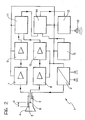
- Figure 2 is a block schematic diagram of the circuit structure of the same device,
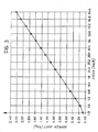
- Figure 3 is a graph showing the operating criteria of the device according to the invention.
- Figure 1 shows schematically how the rear-view mirrors normally mounted on motor vehicles are not able to provide the driver with a complete view of the underlying space.
- In the example illustrated, a first motor car, indicated A, has a rear-view mirror B; this gives the driver a view of the space behind over an angular field C (the first spatial region) which extends rearwardly of the motor car A through a given angular amplitude (typically of the order of 18-20°) from the direction of travel D of the motor vehicle A up to a limit of observation line E. There is therefore a wide obscured or blind region which is not "covered" by the rear-view mirror B and which becomes wider the close it is to the vehicle A. The presence of this obscured or blind region means that another vehicle, such as a car F which is overtaking, is, in effect, invisible to the driver of the vehicle A through the rear-view mirror B. This can give rise to very dangerous travelling conditions, with risk of collision should the driver of the vehicle decide for any reason (for example the presence of an obstacle) to swerve sideways and to the left from his line of travel up to that time.
- The device according to the invention is constituted essentially by an electromagnetic wave (microwave) sensor and acts, so to speak, like radar surveying a second spatial region behind the vehicle A, that is the blind or dead region not covered by the rear-view mirror B. The device is intended to provide corresponding information to the driver of the car A when another vehicle, such as the vehicle F of Figure 1, is in that region and moving closer to the car A. The device 1 according to the invention is therefore able to detect the direction of movement of the vehicle F which could come into collision with the vehicle A on which the device 1 is mounted. As already stated, this discrimination is necessary since the device 1 is mounted on a motor vehicle and itself moves relative to the road, to everything which is stationary (for example parked vehicles), to anything which is moving at a relatively slower speed and, naturally, to vehicles which are moving away from the vehicle A. These latter vehicles will certainly not give rise to a risk of collision with the motor vehicle A and an indication of their presence would therefore be distracting to the driver of the motor car A.
- In general, the angular extent of the cover provided by the device 1 is defined by a main lobe having an aperture of the order of 10-60°, preferably 30-45°, oriented so that the axis L₁ of the main lobe L is at approximately 45° to the direction of movement D of the vehicle.
- Naturally, although the positioning of the device 1 near the rear-view mirror can undoubtedly be advantageous (also from the possibility of integrating the device 1 with the rear-view mirror), other mounting arrangements are possible and, in particular, it may be positioned on other parts of the motor vehicle A, for example near its rear end.
- With reference to the block diagram of Figure 2, a supply unit is indicated 2 and, as well as providing a stabilised supply voltage (8 volts dc) to all the components of the device 1, it also provides a modulated supply to a
microwave generator 3. The latter is preferably constituted by a Gunn diode mounted in a cavity which forms part of a trumpet wave-guide cavity unit 4 which faces outwardly of the device 1 so as to create the lobe L of Figure 1. - The Gunn
diode 3 preferably operates at a frequency of the order of 2-24 GHz. - This selection is dictated by the need to minimise the dimensions of the unit 4 and of the device 1 as a whole whilst keeping the gain of the antenna high (for example 17 dB). It is important for the gain to be sufficient to keep the angular amplitude of the radiation lobe L contained. This is to prevent secondary lobes, which are inclined to the axis L₁ of the main lobe, from providing false indications. This may occur during movement very close to a row of motor vehicles parked at the side of the street, or during passage close to other vehicles travelling in the opposite direction.
- Moreover, the
supply 2 introduces a small ultra-sound-frequency ripple (for example 30-40 KHz) into the supply voltage of theGunn diode 3. The fact that the supply to themicrowave generator 3 is modulated prevents interference between two or more collision-prevention devices 1 according to the invention mounted on two vehicles which pass each other at a distance less than or equal to the range of the device. - Two microwave detectors indicated 5 and 6, preferably constituted by two Schottky diodes, are mounted within the unit 4 so as to be struck by the radiation emitted by the
generator 3 and reflected by obstacles situated within the spatial region investigated ( lobe L) - The two
detectors Gunn diode 5. - In other words d = (2n + 1). λ/4.
- Since they are located within the unit 4, the two
diodes - The signals resulting from the detection of the reflected waves are sent to two
respective amplifier blocks 7 and 8. - Their separation by a distance d which is an odd multiple of a quarter of the wavelength makes the
detectors diode 3 as a result of its reflection from a moving obstacle. - The amplitude of this shift is shown in KHz on the ordinate scale of the graph of Figure 3 as a function of the velocity of the device 1, and hence of the vehicle on which it is mounted, relative to other vehicles, which is shown on the abscissa in Km/hour.
- The present invention is therefore based on the use of a Doppler-effect movement detector which operates as a transceiver. In fact there is a transmission section (the Gunn diode 3) which supplies high-frequency power (in the microwave range) and an antenna circuit such as to achieve impedance-matching between the generator and the medium in which the electromagnetic waves are propagated.
- The receiver section also uses an antenna which is usually, but not necessarily, the same as that used by the transmitter. The Schottky
diodes Gunn diode 3 and with the signal reflected from the environment. The beat frequency of these two signals of the same frequency is therefore zero. Only when an object of sufficient size moves into the irradiation lobe of the unit 4 is the frequency of the signal received shifted by the Doppler effect. In this case, the value of the frequency difference is other than zero. The frequency shift varies from a few tenths of a Hz to many kHz. - Because of regulations relating to the use of the electromagnetic spectrum as regards microwave detectors, the manufacturer has been obliged to set the transmitter frequency to a well-defined value. Clearly, under these conditions, two devices situated at a distance apart at least equal to the nominal range, could interfere with each other if the two transmission frequencies differed only slightly, that is from a few Hz to several KHz. In the present case, the frequency modulation of the transmission oscillator (the Gunn diode 3) with an ultrasound frequency prevents the beat frequency from occurring in the pass-band regions of the
amplifiers 7 and 8 of the receiver section. - In general the two
amplification channels 7 and 8 are formed so as to have a frequency response which enables the detection of velocities from a little less than 2 km/hour up to a maximum of 50 km/hour. - After being squared by passage through respective squaring circuits (triggers) 9, 10, the detection signals are applied to a phase-sensitive circuit (psd) 11 which acts as a discriminator for distinguishing the direction of the Doppler shift detected in the reflected waves.
- As is known, the direction of the shift depends on the direction of movement of the device relative to the reflection source (in the specific case, other vehicles which are moving in the observation zone).
- In general, the Doppler shift will be positive (+ Δ f) in the presence of a vehicle which is approaching and negative (- Δ f ) in the case of a vehicle moving away.
- The
phase detector 11 is formed so as to provide an output signal only when the phase shift indicates the presence of an approaching vehicle. - This signal can be used directly, through a
relay 12, to switch on awarning device 13, such as an acoustic warning (a buzzer) mounted in the passenger compartment of the motor vehicle, so as to warn the driver of the dangerous situation. - In the embodiment of the invention which is currently preferred, the signal output by the
phase detector 11 is applied to therelay 12 through an enablingunit 14 which is sensitive to a vehicle-speed signal taken from atachometric sensor 15. - The latter sensor may be any sensor currently used in the most recent generation of vehicles for providing speed information to members, such as the automatic gear change or the vehicle's trip computer, or simply by any sensor which can provide an electrical signal indicative of the speed of movement of the vehicle.
- The
discriminator circuit 14 "senses" the tachometric signal provided by thesensor 15 and operates differently according to whether the vehicle A on which the device 1 is mounted is in a normal travelling condition or is in a particular condition (typically stationary or reversing). - Under normal travelling conditions (a tachometric signal positive), the indication, with the consequent activation of the
warning device 13, is effected in the presence of Doppler-shifted signals indicative of approach speeds within a first given range, for example 2-50 km per hour. - Conversely, when the vehicle is stationary or reversing, (a zero or negative tachometric signal) the sensitivity threshold of the
circuit 14 is raised, causing a signal to be sent to therelay 12 only in the presence of Doppler shifts corresponding to approach speeds in a second, narrower range, typically from 20 to 50 km per hour. - The first indication range, which is used under normal travelling conditions of the vehicle, therefore extends to lower speeds. The need for a second, narrower sensitivity range under conditions of stoppage or reversing, is dictated by the need to avoid the emission of unjustified signals under these conditions, for example when another vehicle is approaching the stationary vehicle slowly, or when the vehicle itself is reversing slowly towards a parked vehicle.
Claims (13)
- means (2, 3) for generating electromagnetic waves which can propagate towards the other vehicles (F) and can be reflected back thereby towards the device (1),
- detector means (5, 6) intended to be struck by the reflected waves and sensitive to the Doppler shift undergone by the electromagnetic waves during their propagation; the shift having first and second directions when the other vehicles(F) are moving closer and further away respectively,
- discriminator means (11) with associated warning means (12, 13) connected (7 to 10) to the detector means (5, 6) and able to activate the warning means (13) when the Doppler shift is in the first direction.
Applications Claiming Priority (2)
| Application Number | Priority Date | Filing Date | Title |
|---|---|---|---|
| IT6804388 | 1988-11-23 | ||
| IT68043/88A IT1223930B (en) | 1988-11-23 | 1988-11-23 | DEVICE FOR DETECTING RELATIVE MOVEMENTS BETWEEN VEHICLES MAINLY IN ANTI-COLLISION FUNCTION |
Publications (2)
| Publication Number | Publication Date |
|---|---|
| EP0370965A2 true EP0370965A2 (en) | 1990-05-30 |
| EP0370965A3 EP0370965A3 (en) | 1990-08-22 |
Family
ID=11307412
Family Applications (1)
| Application Number | Title | Priority Date | Filing Date |
|---|---|---|---|
| EP89830483A Withdrawn EP0370965A3 (en) | 1988-11-23 | 1989-11-07 | A device for detecting relative movement between vehicles, mainly for preventing collisions |
Country Status (2)
| Country | Link |
|---|---|
| EP (1) | EP0370965A3 (en) |
| IT (1) | IT1223930B (en) |
Cited By (12)
| Publication number | Priority date | Publication date | Assignee | Title |
|---|---|---|---|---|
| DE4119579A1 (en) * | 1991-06-14 | 1992-12-17 | Bayerische Motoren Werke Ag | Object detector for vehicle blind spot - prevents opening of door by activating door brake when approaching object is detected |
| GB2265744A (en) * | 1992-03-30 | 1993-10-06 | Leonard Lloyd Jones | A motor vehicle blind-spot indicator and warning system |
| WO1994011755A1 (en) * | 1992-11-10 | 1994-05-26 | Siemens Aktiengesellschaft | Microwave doppler module |
| DE4306026A1 (en) * | 1993-02-26 | 1994-09-01 | Krauss Maffei Ag | Towing vehicle for aircraft |
| EP0673802A1 (en) * | 1994-03-26 | 1995-09-27 | Reitter & Schefenacker GmbH & Co. KG | Supervisory apparatus for the driver and/or passenger of vehicles, preferably heavy vehicles |
| WO1997025630A1 (en) * | 1996-01-05 | 1997-07-17 | Traiber, S.A. | Device for the prevention of body injuries, specially in the spinal column and the cervical vertebra, applicable to motor vehicles |
| EP0834424A1 (en) * | 1996-10-07 | 1998-04-08 | MEKRA Lang GmbH & Co. KG | Monitoring device of blind and visible zones around vehicles |
| US6369702B1 (en) | 1999-02-05 | 2002-04-09 | Lang-Mekra North America, Llc | Rearview mirror with safety catch |
| US6486825B1 (en) | 2001-05-02 | 2002-11-26 | Omaha Airport Authority | Runway incursion detection and warning system |
| US6744353B2 (en) | 1999-12-15 | 2004-06-01 | Sjoenell Goeran | Blind spot detector |
| US6995687B2 (en) | 2001-06-22 | 2006-02-07 | Lang-Mekra North America, Llc | Parking aid for use in a motor vehicle |
| US7394355B2 (en) | 2004-02-02 | 2008-07-01 | Sjoenell Goeran | Vehicle collision detector |
Citations (5)
| Publication number | Priority date | Publication date | Assignee | Title |
|---|---|---|---|---|
| US3046548A (en) * | 1958-08-13 | 1962-07-24 | Sylvania Electric Prod | Collision warning device |
| US3697985A (en) * | 1970-09-23 | 1972-10-10 | Bendix Corp | Rear end warning system for automobiles |
| US3898652A (en) * | 1973-12-26 | 1975-08-05 | Rashid Mary D | Vehicle safety and protection system |
| FR2265105A1 (en) * | 1974-03-21 | 1975-10-17 | Radiotechnique Compelec | Microwave radar for vehicle or intruder alarm - uses semiconductor diode oscillator in transmitter |
| WO1985001114A1 (en) * | 1983-08-25 | 1985-03-14 | Galland Jean Claude | Scanning of the dead angle of the optical rear-viewing for vehicles |
-
1988
- 1988-11-23 IT IT68043/88A patent/IT1223930B/en active
-
1989
- 1989-11-07 EP EP89830483A patent/EP0370965A3/en not_active Withdrawn
Patent Citations (5)
| Publication number | Priority date | Publication date | Assignee | Title |
|---|---|---|---|---|
| US3046548A (en) * | 1958-08-13 | 1962-07-24 | Sylvania Electric Prod | Collision warning device |
| US3697985A (en) * | 1970-09-23 | 1972-10-10 | Bendix Corp | Rear end warning system for automobiles |
| US3898652A (en) * | 1973-12-26 | 1975-08-05 | Rashid Mary D | Vehicle safety and protection system |
| FR2265105A1 (en) * | 1974-03-21 | 1975-10-17 | Radiotechnique Compelec | Microwave radar for vehicle or intruder alarm - uses semiconductor diode oscillator in transmitter |
| WO1985001114A1 (en) * | 1983-08-25 | 1985-03-14 | Galland Jean Claude | Scanning of the dead angle of the optical rear-viewing for vehicles |
Non-Patent Citations (2)
| Title |
|---|
| PROCEEDINGS OF THE IEEE, vol. 62, no. 6, June 1974, pages 804-822, New York, US; D.M. GRIMES et al.: "Automotive radar: A brief review" * |
| RADIO & ELECTRONIC ENGINEERING, vol. 47, no. 10, October 1977, pages 472-476, London, GB; R.D. CODD: "Recent trends in automotive radar" * |
Cited By (17)
| Publication number | Priority date | Publication date | Assignee | Title |
|---|---|---|---|---|
| DE4119579A1 (en) * | 1991-06-14 | 1992-12-17 | Bayerische Motoren Werke Ag | Object detector for vehicle blind spot - prevents opening of door by activating door brake when approaching object is detected |
| GB2265744A (en) * | 1992-03-30 | 1993-10-06 | Leonard Lloyd Jones | A motor vehicle blind-spot indicator and warning system |
| WO1994011755A1 (en) * | 1992-11-10 | 1994-05-26 | Siemens Aktiengesellschaft | Microwave doppler module |
| DE4306026A1 (en) * | 1993-02-26 | 1994-09-01 | Krauss Maffei Ag | Towing vehicle for aircraft |
| US5516252A (en) * | 1993-02-26 | 1996-05-14 | Krauss Maffei Aktiengesellschaft | Turnout protection for aircraft tractor |
| DE4306026C2 (en) * | 1993-02-26 | 1997-09-18 | Krauss Maffei Ag | Aircraft towing vehicle |
| EP0673802A1 (en) * | 1994-03-26 | 1995-09-27 | Reitter & Schefenacker GmbH & Co. KG | Supervisory apparatus for the driver and/or passenger of vehicles, preferably heavy vehicles |
| ES2114801A1 (en) * | 1996-01-05 | 1998-06-01 | Traiber S A | Device for the prevention of body injuries, specially in the spinal column and the cervical vertebra, applicable to motor vehicles |
| WO1997025630A1 (en) * | 1996-01-05 | 1997-07-17 | Traiber, S.A. | Device for the prevention of body injuries, specially in the spinal column and the cervical vertebra, applicable to motor vehicles |
| EP0834424A1 (en) * | 1996-10-07 | 1998-04-08 | MEKRA Lang GmbH & Co. KG | Monitoring device of blind and visible zones around vehicles |
| US5963127A (en) * | 1996-10-07 | 1999-10-05 | Mekra Lang Gmbh & Co. Kg | Control equipment for difficult to see or blind spot areas around vehicles, and related method |
| US6369702B1 (en) | 1999-02-05 | 2002-04-09 | Lang-Mekra North America, Llc | Rearview mirror with safety catch |
| US6744353B2 (en) | 1999-12-15 | 2004-06-01 | Sjoenell Goeran | Blind spot detector |
| US6486825B1 (en) | 2001-05-02 | 2002-11-26 | Omaha Airport Authority | Runway incursion detection and warning system |
| US6995687B2 (en) | 2001-06-22 | 2006-02-07 | Lang-Mekra North America, Llc | Parking aid for use in a motor vehicle |
| US7394355B2 (en) | 2004-02-02 | 2008-07-01 | Sjoenell Goeran | Vehicle collision detector |
| USRE44331E1 (en) | 2004-02-02 | 2013-07-02 | Livy SRVCS, Limited Liability Company | Vehicle collision detector |
Also Published As
| Publication number | Publication date |
|---|---|
| IT8868043A0 (en) | 1988-11-23 |
| EP0370965A3 (en) | 1990-08-22 |
| IT1223930B (en) | 1990-09-29 |
Similar Documents
| Publication | Publication Date | Title |
|---|---|---|
| EP0740166B1 (en) | Compact vehicle based rear and side obstacle detection system including multiple antennae | |
| EP0906581B1 (en) | Vehicle radar system | |
| US6025796A (en) | Radar detector for pre-impact airbag triggering | |
| US5467072A (en) | Phased array based radar system for vehicular collision avoidance | |
| US5999092A (en) | Antenna cluster for a motor road vehicle collision warning system | |
| EP0974851B1 (en) | Method and apparatus for rejecting rain clutter in a radar system | |
| US5339075A (en) | Vehicular collision avoidance apparatus | |
| US6121916A (en) | Method and apparatus for recognizing stationary objects with a moving side-looking radar | |
| JP4007498B2 (en) | Automotive radar equipment | |
| JPS5844228B2 (en) | Obstacle detection radar for vehicles | |
| US6429804B1 (en) | Motor-vehicle-mounted radar apparatus | |
| EP1309464B1 (en) | Safe distance algorithm for adaptive cruise control | |
| JP3411866B2 (en) | Millimeter wave radar device | |
| KR950703158A (en) | SMART BLIND SPOT SENSOR | |
| EP1548458A2 (en) | Vehicle-mounted radar | |
| EP0370965A2 (en) | A device for detecting relative movement between vehicles, mainly for preventing collisions | |
| JP2001027669A (en) | Sensor device for vehicle impact detection | |
| US7129839B2 (en) | Device for monitoring an area | |
| US20090167514A1 (en) | Combined Radar Backup Assist and Blindspot Detector and Method | |
| JP2004531726A (en) | Sensor system for determining the surrounding environment of a car | |
| JPS6024479A (en) | Rear warning apparatus for vehicle | |
| JPH04313090A (en) | Obstacle detecting apparatus for automobile | |
| JPH06160518A (en) | On-vehicle radar device | |
| Lyons et al. | A low-cost MMIC based radar sensor for frontal, side or rear automotive anticipatory precrash sensing applications | |
| KR100190616B1 (en) | Apparatus and method for preventing collision of automobile |
Legal Events
| Date | Code | Title | Description |
|---|---|---|---|
| PUAI | Public reference made under article 153(3) epc to a published international application that has entered the european phase |
Free format text: ORIGINAL CODE: 0009012 |
|
| AK | Designated contracting states |
Kind code of ref document: A2 Designated state(s): AT BE CH DE ES FR GB GR IT LI LU NL SE |
|
| PUAL | Search report despatched |
Free format text: ORIGINAL CODE: 0009013 |
|
| AK | Designated contracting states |
Kind code of ref document: A3 Designated state(s): AT BE CH DE ES FR GB GR IT LI LU NL SE |
|
| 17P | Request for examination filed |
Effective date: 19901218 |
|
| 17Q | First examination report despatched |
Effective date: 19930309 |
|
| STAA | Information on the status of an ep patent application or granted ep patent |
Free format text: STATUS: THE APPLICATION IS DEEMED TO BE WITHDRAWN |
|
| 18D | Application deemed to be withdrawn |
Effective date: 19930921 |